RVS4000-QI-Rev_NC
知识分享-汽车网络技术

大众速腾动力总线系统
版权所有 © 浙江吉利汽车研究院有限公司
Copyright Reserved © Geely Automobile Research Institute
大众速腾舒适总线系统
版权所有 © 浙江吉利汽车研究院有限公司
Copyright Reserved © Geely Automobile Research Institute
版权所有 © 浙江吉利汽车研究院有限公司
Copyright Reserved © Geely Automobile Research Institute
6
大众速腾网络系统
版权所有 © 浙江吉利汽车研究院有限公司
Copyright Reserved © Geely Automobile Research Institute
汽车网络系统分类
SAE车辆通信与控制委员会将汽车数据传输 网划分为A、B、C、D四类。 A类是面向传感器/执行器控制的低速网络, 数据传输位速率通常小于10kb/s; B类是面向独立模块间数据共享的中速网络, 位速率一般在10kb/s到125kb/s之间; C类是面向高速、实时控制的多路传输网, 位速率在125kb/s到1Mb/s之间; D类主要用于信息与多媒体系统网络,通信 速率大于1Mb/s。
版权所有 © 浙江吉利汽车研究院有限公司
Copyright Reserved © Geely Automobile Research Institute
汽车电子网络技术
汽车电子网络技术是现代汽车电子技术的重要 组成部分,是现代汽车通信与控制的基础。 就像汽车电子技术在20世纪70年代引入集成 电路、80年代引入微控制器一样,近10多年来数 据总线技术的引入也将是汽车电子技术发展的一 个里程碑。
Motorola 3.5 kHz 产品说明书

RVN4126 3.59100-386-9100-386/T DEVICERVN41772-CD2-3.5MCS/MTSRVN41821-CD2-3.5XTS3000/SABER PORTABLE YES RKN4046KHVN9085 3.51-20 R NO HLN9359 PROG. STAND RVN4057 3.532 X 8 CODEPLUG NO3080385B23 & 5880385B30 MDVN4965 3.59100-WS/T CONFIG KITRVN4053 3.5ASTRO DIGITAL INTERFACE NO3080385B23RVN41842-CD RKN4046A (Portable) 2-3.5ASTRO PORTABLE /MOBILE YES3080369B73 or0180300B10 (Mobile) RVN41831-CD3080369B732-3.5ASTRO SPECTRA MOBILE YES(Low / Mid Power)0180300B10 (High Power) RVN4185CD ASTRO SPECTRA PLUS MOBILE NO MANY OPTIONS; SEESERVICE BRIEF#SB-MO-0101RVN4186CD ASTRO SPECTRA PLUS MANY OPTIONS;MOBILE/PORTABLE COMB SEE SERVICE BRIEF#SB-MO-0101RVN4154 3.5ASTROTAC 3000 COMPAR.3080385B23RVN5003 3.5ASTROTAC COMPARATORS NO3080399E31 Adpt.5880385B34RVN4083 3.5BSC II NO FKN5836ARVN4171 3.5C200RVN4029 3.5CENTRACOM SERIES II NO VARIOUS-SEE MANUAL6881121E49RVN4112 3.5COMMAND PLUS NORVN4149 3.5COMTEGRA YES3082056X02HVN6053CD CT250, 450, 450LS YES AAPMKN4004RVN4079 3.5DESKTRAC CONVENTIONAL YES3080070N01RVN4093 3.5DESKTRAC TRUNKED YES3080070N01RVN4091 3.5DGT 9000 DESKSET YES0180358A22RVN4114 3.5GLOBAL POSITIONING SYS.NO RKN4021AHVN8177 3.5GM/GR300/GR500/GR400M10/M120/130YES3080070N01RVN4159 3.5GP60 SERIES YES PMLN4074AHVN9128 3.5GP300 & GP350RVN4152 3.5GP350 AVSRVN4150 3.5GTX YES HKN9857 (Portable)3080070N01(Mobile) HVN9025CD HT CDM/MTX/EX SERIES YES AARKN4083/AARKN4081RiblessAARKN4075RIBLESS NON-USA RKN4074RVN4098H 3.5HT1000/JT1000-VISAR YES3080371E46(VISAR CONV)RVN4151 3.5HT1000 AVSRVN4098 3.5HT1000/ VISAR CONV’L.YES RKN4035B (HT1000) HVN9084 3.5i750YES HLN-9102ARVN4156 3.5LCS/LTS 2000YES HKN9857(Portable)3080070N01(Mobile) RVN4087 3.5LORAN C LOC. RECV’R.NO RKN4021ARVN4135 3.5M100/M200,M110,M400,R100 includesHVN9173,9177,9646,9774YES3080070N01RVN4023 3.5MARATRAC YES3080070N01RVN4019 3.5MAXTRAC CONVENTIONAL YES3080070N01RVN4139 3.5MAXTRAC LS YES3080070N01RVN4043 3.5MAXTRAC TRK DUPLEX YES3080070N01RVN4178CD MC SERIES, MC2000/2500DDN6124AW/DB25 CONNECTORDDN6367AW/DB9 CONNECTOR RVN41751-CD Rib to MIC connector 1-3.5MCS2000 RKN4062BRVN41131-3.5MCS2000RVN4011 3.5MCX1000YES3000056M01RVN4063 3.5MCX1000 MARINE YES3000056M01RVN4117 3.5MDC/RDLAP DEVICESRVN4105 3.5MOBILE PROG. TOOLRVN4119 3.5MOBITEX DEVICESRVN4128 3.5MPT1327-1200 SERIES YES SEE MANUALRVN4025 3.5MSF5000/PURC/ANALOG YES0180355A30RVN4077 3.5MSF5000/10000FLD YES0180355A30RVN4017K 3.5MT 1000YES RTK4205CRVN4148 3.5MTR 2000YES3082056X02RVN4140 3.5MTRI 2000NORVN41761-CD MTS2000, MT2000*, MTX8000, MTX90001-3.5*programmed by DOS which is included in the RVN4176RVN4131 3.5MTVA CODE PLUG FIXRVN4142 3.5MTVA DOCTOR YES3080070N01RVN4131 3.5MTVA3.EXERVN4013 3.5MTX800 & MTX800S YES RTK4205CRVN4097 1-CD MTX8000/MTX9000,MTS2000,MT2000*,* programmed by DOS which is included in the RVN4176HVN9067CD MTX850/MTX8250MTX950,MTX925RVN4138 3.5MTX-LS YES RKN4035DRVN4035 3.5MX 1000YES RTK4203CRVN4073 3.5MX 800YES RKN4006BHVN9395 P100, P200 LB, P50+, P210, P500, PR3000RVN4134 3.5P100 (HVN9175)P200 LB (HVN9794)P50+ (HVN9395)P210 (HVN9763)P500 (HVN9941)PR3000 (HVN9586)YES RTK4205HVN9852 3.5P110YES HKN9755A/REX1143 HVN9262 3.5P200 UHF/VHF YES RTK4205RVN4129 3.5PDT220YVN4051 3.5PORTABLE REPEATER Portable rptr.P1820/P1821AXRVN4061C 3.5PP 1000/500NO3080385B23 & 5880385B30 RVN5002 3.5QUANTAR/QUANTRO NO3O80369E31RVN4135 3.5R100 (HVN9177)M100/M200/M110/M400YES0180358A52RVN4146 3.5RPM500/660RVN4002 3.5SABER YES RTK4203CRVN4131 3.5SETTLET.EXEHVN9007 3.5SM50 & SM120YESRVN4039 3.5SMART STATUS YES FKN5825AHVN9054 3.5SOFTWARE R03.2 P1225YES3080070N01HVN9001 3.5SOFTWARE R05.00.00 1225LS YES HLN9359AHVN9012 3.5SP50RVN4001N 3.5SPECTRA YES3080369B73 (STANDARD)0180300B10 (HIGH POWER) RVN4099 3.5SPECTRA RAILROAD YES3080369B73RVN4110 3.5STATION ACCESS MODULE NO3080369E31RVN4089A 3.5STX TRANSIT YES0180357A54RVN4051 3.5SYSTEMS SABER YES RTK4203BRVN4075 3.5T5600/T5620 SERIES NO3080385B23HVN9060CD TC3000, TS3000, TR3000RVN4123 3.5VISAR PRIVACY PLUS YES3080371E46FVN4333 3.5VRM 100 TOOLBOX FKN4486A CABLE &ADAPTORRVN4133 3.5VRM 500/600/650/850NORVN4181CD XTS 2500/5000 PORTABLES RKN4105A/RKN4106A RVN41002- 3.5XTS3000 ASTRO PORTABLE/MOBILERVN4170 3.5XTS3500YES RKN4035DRIB SET UPRLN4008E RADIO INTERFACE BOX (RIB)0180357A57RIB AC POWER PACK 120V0180358A56RIB AC POWER PACK 220V3080369B71IBM TO RIB CABLE (25 PIN) (USE WITH XT & PS2)3080369B72IBM TO RIB CABLE (9 PIN)RLN443825 PIN (F) TO 9 PIN (M) ADAPTOR (USE W/3080369B72 FOR AT APPLICATION) 5880385B308 PIN MODULAR TO 25 PIN ”D” ADAPTOR (FOR T5600 ONLY)0180359A29DUPLEX ADAPTOR (MOSTAR/TRAXAR TRNK’D ONLY)Item Disk Radio RIB Cable Number Size Product Required Number Item Disk Radio RIB Cable Number Size Product Required NumberUtilizing your personal computer, Radio Service Software (RSS)/Customer Programming Software (CPS)/CustomerConfiguration Software (CCS) enables you to add or reprogram features/parameters as your requirements change. RSS/CPS/CCS is compatible with IBM XT, AT, PS/2 models 30, 50, 60 and 80.Requires 640K RAM. DOS 3.1 or later. Consult the RSS users guide for the computer configuration and DOS requirements. (ForHT1000, MT/MTS2000, MTX838/8000/9000, Visar and some newer products —IBM model 386, 4 MEG RAM and DOS 5.0 or higher are recommended.) A Radio Interface Box (RIB) may be required as well as the appropriate cables. The RIB and cables must be ordered separately.Licensing:A license is required before a software (RVN) order is placed. The software license is site specific (customer number and ultimate destination tag). All sites/locations must purchase their own software.Be sure to place subsequent orders using the original customer number and ship-to-tag or other licensed sites; ordering software without a licensed customer number and ultimate tag may result in unnecessary delays. To obtain a no charge license agreement kit, order RPX4719. To place an order in the U.S. call 1-800-422-4210. Outside the U.S., FAX 847-576-3023.Subscription Program:The purchase of Radio ServiceSoftware/Customer Programming/Customer ConfigurationSoftware (RVN & HVN kits) entitles the buyer/subscriber to three years of free upgrades. At the end of these three years, the sub-scriber must purchase the same Radio Service Software kit to receive an additional three years of free upgrades. If the sub-scriber does not elect to purchase the same Radio Service Software kit, no upgrades will be sent. Annually a subscription status report is mailed to inform subscribers of the RSS/CPS/CCS items on our database and their expiration dates.Notes:1)A subscription service is offered on “RVN”-Radio Service Software/Customer Programming/Customer Configuration Software kits only.2)“RVN” software must only be procured through Radio Products and Services Division (RPSD). Software not procured through the RPSD will not be recorded on the subscription database; upgrades will not be mailed.3)Upgrades are mailed to the original buyer (customer number & ultimate tag).4)SP software is available through the radio product groups.The Motorola General Radio Service Software Agreement is now available on Motorola Online. If you need assistance please feel free to submit a “Contact Us” or call 800-422-4210.SMART RIB SET UPRLN1015D SMART RIB0180302E27 AC POWER PACK 120V 2580373E86 AC POWER PACK 220V3080390B49SMARTRIB CABLE (9 PIN (F) TO 9 PIN (M) (USE WITH AT)3080390B48SMARTRIB CABLE (25 PIN (F) TO 9 PIN (M) (USE WITH XT)RLN4488ASMART RIB BATTERY PACKWIRELESS DATA GROUP PRODUTS SOFTWARERVN4126 3.59100-386/9100T DEVICES MDVN4965 3.59100-WS/T CONFIG’TN RVN41173.5MDC/RDLAP DEVICESPAGING PRODUCTS MANUALS6881011B54 3.5ADVISOR6881029B90 3.5ADVISOR ELITE 6881023B20 3.5ADVISOR GOLD 6881020B35 3.5ADVISOR PRO FLX 6881032B30 3.5BR8506881032B30 3.5LS3506881032B30 3.5LS5506881032B30 3.5LS7506881033B10 3.5LS9506881035B20 3.5MINITOR III8262947A15 3.5PAGEWRITER 20008262947A15 3.5PAGEWRITER 2000X 6881028B10 3.5TALKABOUT T3406881029B35 3.5TIMEPORT P7308262947A15 3.5TIMEPORT P930NLN3548BUNIVERSAL INTERFACE KITItem Disk Radio NumberSize Product。
7000操作手册(CNs400_1600_4000)

C-I 类
260 2000 B 120 K 415 5X-带有附件 F-3R 类
400
3000 4000
C 208 L 440
D 220 M 460
G-4 类 L-12 类
E 230 N 480
M-3R 类保证
F 240 P 550
N-4 类保证
G 277 Q 575
P-4 类保证
H 380 R 600
小心
本手册中小心用以警告可能的设备损坏。
额定值标签
每台自动转换开关均有一个额定值标签 以说明负载额定值和故障电路耐受/关合额定 值。参见转换开关上额定标签。
警告
不允许超过额定值标签上所示的值。超出额 定值会导致人身伤害或设备严重损坏。
铭牌和目录号标识
转换开关铭牌包含每一台 7000 系列 ATS 的参数。只能在铭牌所示的极限值范 围内使用 ATS。典型的目录号如下所示, 其中包括各个单元的解释。
绿
红
绿
红
图 1-11 标准的控制及指示
2 – 电压检查
1 闭合常用电源断
首先检查转换开关上的铭牌。额定电压须
路器,负载使用常 用电源及常用电
与常用和备用电源的线电压相同。
源有效灯会亮。
小心
检查馈线已接至相应的端子上
2 用精确的电压表 在常用电源接头 处测量相间电压
及线间电压。然后
危险
使用仪表测量电压时,应特别小心。不能碰 触电源接线端;会导致电击、灼伤或死亡
3
本程序中,常用及备用供电电源须可用, 且紧急供电引擎(如使用)须能启动。
执行右边第 1 – 5 步。观察状态灯。
4
● 黑色块表示灯亮 ○ 白色块表示灯灭
奥的斯电梯调试资料

调试手册奥的斯电梯有限公司文件编号:OH-CONB863_SUR_ZH原始会签记录授权AUTH. CAL4804部件版本This work and the information it contains are the property of Xizi Otis Elevator Company (“XOEC”). It is delivered~others on the express condition that it will be used only for, or on behalf of, XOEC; that neither it nor the information it contains will be reported or disclosed, in whole or in part, without the prior written consent of XOEC, and that on demand it and any copies will be promptly returned~XOEC.目录1概述.............................................................................................................. 错误!未定义书签。
2检修模式运行条件检查 ................................................................................ 错误!未定义书签。
3检修模式GECB上电检查 ............................................................................. 错误!未定义书签。
4变频器参数设置 ........................................................................................... 错误!未定义书签。
西门子工程师知识库
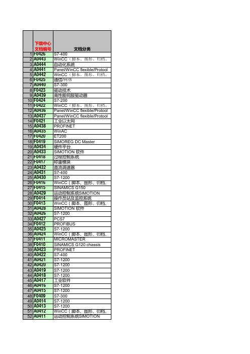
,掉电保持Step7,WinCC,WinCC Flexible CMI冗余80B1,普通网卡,Step7,iMap ,以太网,通信指令Modbus TCP,保持寄存器,输入寄存器,读写,服,使用方法,实例,输入寄存器,读写,服务器,客户端,Modscan32,Modbus 工厂复位,IP地址,网络流量,WinAC监控器, IO 控制器, IO 设备地址,ISO,SCE中PC Station使用的常见问题 Q1:为什么在STEP 7中配T400的参数。
SFB12,SFB13TCP/IP的S7通讯PCS 7项目指定典型设置。
当您在PCS 7 中版软件介绍了安装及配置过程。
,软PLC仪表辅助变量的一种方式。
ASM456,对RF300进行操作的例子,使读者对RFID的系MDS)、天线、RF300、ASM456、PLC、PROFIBUFM进行Firmware的常规过程步骤及更新过程中或一些特殊的SFB52/53,通过读写数据记录的方式对ET200S FC(Firmwa ,参数读写,数据记录数据记录路由、电子设备描述文件,软PLCPROFINET IO通讯还可以使用IRT的等时PROFINET中,用于管理和维护网络,例如SNMP和HTTP 的重量,如何进行校秤、如何进行诊断。
软件、零点、标定砝码MicroScale_ V20和MicroScale_additional的功能进行介CP5611A2、CP5613、CP5613A2、CP5614、CP5614A2、MMC卡插802.1XTCP通信的方法作了完整的描述,编程,编程UDP通信的方法作了完整的描述,STEP7,编程ISO on TCP通信的方法作了完整有何区别?,分辨率为1600万,可以用于静态称重、皮带秤、失重秤。
RMVC系列高压变频调速装置-卧龙荣信

RMVC 系列高压变频器技术参数及型号...................................................................... 08 技术参数 ............................................................................................................................. 08 变频器产品型号定义 .......................................................................................................... 08
NX Advanced FEM产品说明说明书

NX Advanced FEM includes the fundamental modeling functions of automatic and manual mesh generation,application of loads and boundary conditions and model development and checking.A robust set of visualization tools generates displays quickly,lets you view multiple results simultane-ously and enables you to easily print the display.In addition,extensive post-processing functions enable review and export of analysis results to spreadsheets and provide extensive graphing tools for gaining an understanding of results.Post-processing also supports the export of JT ™data for collaboration across the enterprise with JT2Go and Teamcenter for lifecycle visualization.NX Advanced FEM provides seamless,transparent support for a number of industry-standard solvers,such as NX Nastran,MSC Nastran,Ansys and Abaqus.For example,when you create either a mesh or a solution in NX Advanced FEM,you specify the solver environment that you plan to use to solve your model and the type of analysis you want to perform.The software then presents all meshing,boundary conditions and solution options using the terminology or “language”of that solver and analysis type.Additionally,you can solve your model and view your results directly in Advanced FEM without having to first export a solver file or import your results.•Advanced FEM features data structures,such as the separate Simulation (.sim)and FEM files (.fem)that help facilitate the development of FE models across a distributed work environment.These data structures also allow analysts to easily share FE data to perform multiple types of analyses.•Advanced FEM offers world-class meshing capabilities.The software is designed to produce a very high quality mesh while using an economic element count.Advanced FEM supports a complete complement of element types (0D,1D,2D and 3D).Additionally,Advanced FEM gives analysts control over specific meshing tolerances that control,for example,how the software meshes complex geometry,such as fillets.•Advanced FEM includes multiple geometry abstraction tools that give analysts the ability to tailor the CAD geometry to the needs of their analysis.For example,analysts can use these tools to improvethe overall quality of their mesh by eliminating problematic geometry,such as tiny edges or slivers.NX Advanced FEMNX/plmfact sheetBenefitsEmbedded tools for 3D geometry creation and editing of both components and assembliesAssociation to the design geometry allows the analyst to work closely with the design engineer•Knowledge of design changes•“On-demand”FE model updates based on design geometry changesSupport for NX Manager and Teamcenter ®software for all created FE data setsSolver environments customized for the nomenclature of the selected solverA full range of tools for FE model generation including predefined constraint conditions and automated mesh mating conditionsVerification of models before processing with a full set of graphical and mathematical tools that help check model suitableAbility to view analysis results quickly and easily with a dynamic visualization toolExtensive post-processing tools to continue the iterative phases of analysis or to export/import informationDirect integration with Simulation Process Studio for CAE "best-practices"knowledge capture;including process wizard templates for vibration and stress analysisIntegrated basic durability analysis SummaryNX Advanced FEM software is a comprehensive multi-CAD finite element modeling and results visualization product that is designed to meet the needs of experienced CAE analysts.It includes a full suite of geometry creation and editing tools as well as FE pre-and post-processing tools and supports a broad range of product performance evaluation solutions.NX Advanced FEM provides 2-way association to NX design geometry,allowing users to rapidly iterate on design changes.Robust CAD translators,along with the embedded industry-standard Parasolid 3D modeling kernel,enable non-native geometry to be easily imported for use within the NX Advanced FEM environment.Siemens PLM Softwareremoval of design artifacts such as sliver faces, the actual design features but rather allows for quality of the mesh.This set of commandsmeshingtriangles or quadrilateral dominant meshes reduce element distortionsbefore meshingrigid bars,spring,gap andfeatures(updates occur with designtypes of analysis and modeling quickly and including linear and parabolic forms ofsprings,dampers,masses,rigid links andsymbols.P-elements(solid tetrahedra)aredisplacementsymbolsmaintained through design geometry changes conditions to correctly simulate nonlinearto Excel(Windows only)for further manipulation and results inspectiononly)or a spreadsheet text fileAnsys,Nastran,etc.Advanced FEM product include: Solution typeLinear statics(SOL101)with surface-to-surface contactNormal modes(SOL103) Response simulation(SOL103) Buckling(SOL105)Nonlinear statics(SOL106)Direct frequency response(SOL108) Direct transient response(SOL109) Modal frequency response(SOL111) Modal transient response(SOL112) Advanced nonlinear(SOL601) Linear and advanced nonlinear transient response(SOL129)transfer(SOL153)ContactSiemens PLM SoftwareAmericas8004985351Europe+44(0)1276702000Asia-Pacific852********/plm©2007.Siemens Product Lifecycle Management Software Inc.All rights reserved.Siemens and the Siemens logo are registered trademarks of Siemens AG. Teamcenter,NX,Solid Edge,Tecnomatix,Parasolid,Femap,I-deas,JT,UGS Velocity Series,Geolus and the Signs of Innovation trade dress are trademarks or registered trademarks of Siemens Product Lifecycle Management Software Inc.or its subsidiaries in the United States and in other countries.All other logos,trademarks,registered trademarks or service marks used herein are the property of their respective holders.9/07。
西门子 NXGPro+ 控制系统手册_操作手册说明书
3.4
单元通讯的协议 ............................................................................................................ 36
3.5
NXGpro+ 高级安全 .......................................................................................................37
3.2
功率拓扑 ......................................................................................................................34
3.3
控制系统概述 ...............................................................................................................35
NXGPro+ 控制系统手册
NXGPro+ 控制系统手册
操作手册
AC
A5E50491925J
安全性信息
1
安全注意事项
2
控制系统简介
3
NXGPro+ 控制系统简介
4
硬件用户界面说明
5
参数配置/地址
6
运行控制系统
7
高级的操作功能
8
软件用户界面
9
运行软件
10
故障和报警检修
11
NETGEAR CM400高速电缆模块说明书

Performance & Use• Eliminate monthly rental fees—Up to $120 per year 1• C able Internet speeds up to 340 Mbps ‡—8 downstream & 4 upstream channels• G igabit Ethernet port for faster access and downloads• C ableLabs ® DOCSIS ® 3.0 Certified to work with cable Internet providers XFINITY ® from Comcast, Spectrum ®, Cox ® , Cablevision and moreCM400 High Speed Cable Modem—DOCSIS ® 3.0Data Sheet CM400OverviewThe NETGEAR CM400 High Speed Cable Modem provides a connection to high-speed cable Internet with speeds up to 340 Mbps †. It is CableLabs ® certified and with DOCSIS ® 3.0 is 8X faster than 2.0. A Gigabit Ethernet port provides faster access and downloads.Connect the CM400 High Speed Cable Modem directly to your computer or wireless router for connecting to other wireless devices.The NETGEAR Difference - CM400• G igabit Ethernet port• DOCSIS ® 3.0 CableLabs ® certified • Supports IPv6• Secure connection • Easy installationFast Cable Internet Access• Up to 340 Mbps † download and upload speed for streaming HD videos,faster downloads, and high-speed online gaming•C ableLabs ® Certified for US cable Internet services - DOCSIS ® 3.0 is 8 times faster than DOCSIS 2.0 devices • W orks with U.S. cable Internet providers like XFINITY ® from Comcast, Spectrum ®, Cox ®, Cablevision & more (not compatible with Cable bundled voice services)• F ast self-activation for XFINITY customers—Get connected without a service call• Save money over time by owning your cable equipment and avoiding monthly rental charges from your Internet provider• Gigabit Ethernet port—Fastest wired speeds to connect your routeror computerORHigh Speed Cable Modem (CM400)Cable Internet ConnectionWireless RouterDesktop or LaptopComputer1Based on a typical monthly equipment rental fee of $10 per month.This product comes with a limited warranty that is valid only if purchased from a NETGEAR authorized reseller.*90-day complimentary technical support following purchase from a NETGEAR authorized reseller.†Maximum rate is derived from DOCSIS ® 3.0 specifications and actual throughput will vary depending on the MSO provisioning and speed tier subscription. Check your cable Internet service provider web site for data speed tier compatibility.NETGEAR makes no express or implied representations or warranties about this product’s compatibility with any future standards.Customer-owned modems may not be compatible with certain cable networks. Please check with your cable provider to confirm this NETGEAR modem is allowed on your cable network. This product is not compatible with Cable bundled voice services.For indoor use only.NETGEAR, and the NETGEAR Logo are trademarks of NETGEAR, Inc. Mac, Mac OS and the Mac logo are trademarks of Apple Inc., registered in the U.S. and other countries. Any other trademarks mentioned herein are for reference purposes only. ©2017 NETGEAR, Inc.NETGEAR, Inc. 350 E. Plumeria Drive, San Jose, CA 95134-1911 USA, /supportD-CM400-5CM400 High Speed Cable Modem—DOCSIS ® 3.0Data Sheet CM400Package Contents• High Speed Cable Modem—DOCSIS 3.0 (CM400)• Stand • Ethernet cable • Quick install guide • Power adapterPhysical Specifications• Dimensions: 5.8 x 3.8 x 1.8 in (147 x 96 x 30 mm)• Weight: 0.44 lb (0.19 kg)Warranty• /warrantyAdvanced Features• Designed to meet DOCSIS 3.0 specifications and backward compatible with DOCSIS 2.0 networks• F ast download and upload speed - 8 x4Channel Bonding enables 340 Mbps † download • IPv6 next generation Internet addressing support• Gigabit Ethernet port with auto-sensing t echnologyTechnical Specifications• Simple—CD-less installation • Memory: 8MB flash and 64MB DDR • Advanced Quality of Service (QoS)• IPv6 support (Internet Protocol Version 6)System Requirements• Cable broadband Internet service • P lease check your cable Internet service provider web site for data speed tier compatibility •M icrosoft ® Windows ® 7, 8, 10, Vista ®, XP ®, 2000, Mac OS ®, or other operating systems running a TCP/IP network • Microsoft ® Internet Explorer ® 5.0, F irefox ® 2.0,Safari ® 1.4, or G oogle Chrome ™11.0 browsers or higherStandards• One (1) LAN Gigabit Ethernet port • One (1) WAN coaxial cable connectionGigabit Ethernet Port to WiFi Router or ComputerCable/Coaxial PortPower。
西门子840D数控系统调试--双清--并配置参数
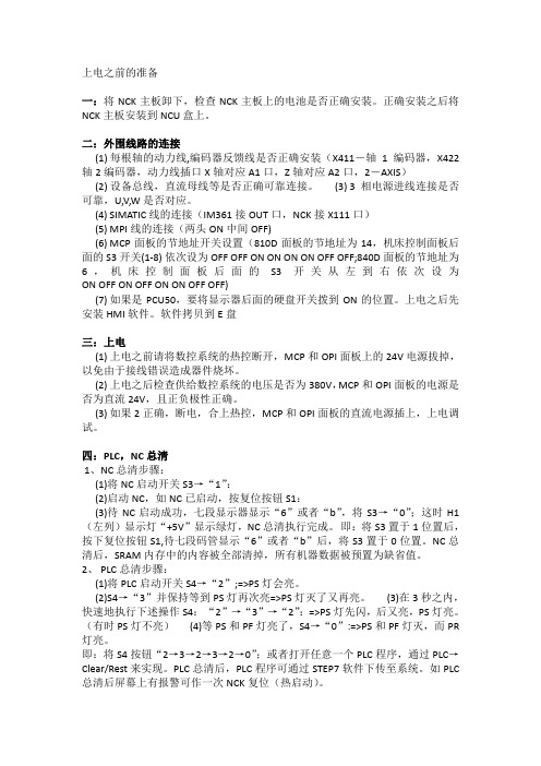
上电之前的准备一:将NCK主板卸下,检查NCK主板上的电池是否正确安装。
正确安装之后将NCK主板安装到NCU盒上。
二:外围线路的连接(1) 每根轴的动力线,编码器反馈线是否正确安装(X411-轴1编码器,X422轴2编码器,动力线插口X轴对应A1口,Z轴对应A2口,2-AXIS)(2) 设备总线,直流母线等是否正确可靠连接。
(3) 3相电源进线连接是否可靠,U,V,W是否对应。
(4) SIMATIC线的连接(IM361接OUT口,NCK接X111口)(5) MPI线的连接(两头ON中间OFF)(6) MCP面板的节地址开关设置(810D面板的节地址为14,机床控制面板后面的S3开关(1-8) 依次设为OFF OFF ON ON ON ON OFF OFF;840D面板的节地址为6,机床控制面板后面的S3开关从左到右依次设为ON OFF ON OFF ON ON OFF OFF)(7) 如果是PCU50,要将显示器后面的硬盘开关拨到ON的位置。
上电之后先安装HMI 软件。
软件拷贝到E盘三:上电(1) 上电之前请将数控系统的热控断开,MCP和OPI面板上的24V电源拔掉,以免由于接线错误造成器件烧坏。
(2) 上电之后检查供给数控系统的电压是否为380V,MCP和OPI面板的电源是否为直流24V,且正负极性正确。
(3) 如果2正确,断电,合上热控,MCP和OPI面板的直流电源插上,上电调试。
四:PLC,NC总清1、NC总清步骤:(1)将NC启动开关S3→“1”:(2)启动NC,如NC已启动,按复位按钮S1:(3)待NC启动成功,七段显示器显示“6”或者“b”,将S3→“0”;这时H1(左列)显示灯“+5V”显示绿灯,NC总清执行完成。
即:将S3置于1位置后,按下复位按钮S1,待七段码管显示“6”或者“b”后,将S3置于0位置。
NC总清后,SRAM内存中的内容被全部清掉,所有机器数据被预置为缺省值。
2、 PLC总清步骤:(1)将PLC启动开关S4→“2”;=>PS灯会亮。
RS CSD7伺服器中文资料下
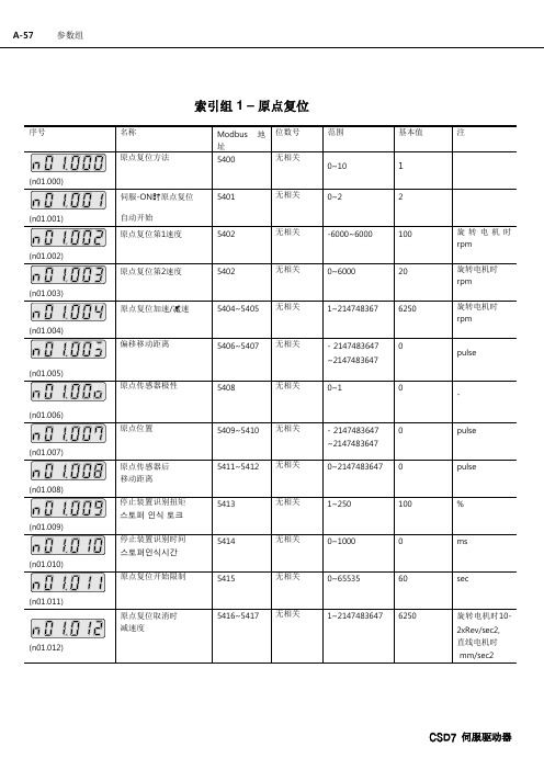
说明 范围 Modbus 地址 适用可能的运行模式
定义电机每1圈负载系统的移动距离。
0~99999 初始值
0
5012~5013 变更可能状态
总是
I
-
单位
用户定义
-
CSD7 伺服驱动器
A-64
(n00.008)
说明 范围 Modbus 地址 适用可能的运行模式
JOG速度命令 RSWare : Drive - Mode Configuration- Indexing – Jog Velocity Command
5602~6603 5854~6855
无相关 无相关
范围
- 2147483647 ~2147483647
- 2147483647 ~2147483647 - 2147483647 ~2147483647
基本值 0 0 0
注 pulse pulse pulse
索引组 7 – 索引等待时间
名称 索引 0 等待时间
pulse
pulse
%
ms
sec
旋转电机时102xRev/sec2, 直线电机时 mm/sec2
CSD7 伺服驱动器
A-58
序号
(n02.000)
(n02.001)
: : :
(n02.127)
索引组 2- 索引选项
名称 索引 0 动作选项
Modbus 地 位数号 址
5800
0
1
2...3
范围
基本值
n08.127)
A-60
: : : 索引 127 速度 (
:
:
:
:
:
:
:
:
:
SINAMICS V60驱动模块简明操作手册_2008123(3)

10
X20 BERO
24 VDC + 电源 -
+24 V 0V
外部 24 V 直流电源
CPM60.1 驱动单元配有一个 24V 的外部直流电源(额定输入电流 2A ), 该电源能使驱动在 24 V (-15% - +20% )的电压范围内正常运行。鉴于直 流电源的性能对于驱动系统的稳定运行至关重要,因此建议选用西门子直流 24 V稳压电源(订货号:6EP1333-3BA00)。如果没有西门子直流 24V 电 源,那么请选用其它品牌的高质量电源。
最小安装间距
为确保散热充分,请在驱动与驱动之间以及驱动与其他设备或者电柜内壁之间 至少留出规定的间距
SINAMICS V60 驱动模块简明操作手册,2008/12
6
A5E01436138
> 100 mm
电柜内壁 > 100 mm
4A/6A
10 A
10 A
> 100 mm
4A/6A > 25 mm
> 25 mm
面板按键
4个轻触开关键
设定值接口 脉冲接口
过载能力
I
Imax
3s
I Imax 0.3 s
In 10s
In
10s
t
t
Imax = 2 x In
可应用负载 惯量
不大于5倍电机转子惯量
控制性能
控制模式
脉冲频率 驱动输入 驱动输出 保护功能 编码器
1.位置控制 (输入模式:脉冲 +方向信号)
2. JOG模式
4. 安装
4.1 机械安装
4.1.1 安装驱动
钻孔样式和外观尺寸
5.5
金关安保VESDA威士达远程部件大全
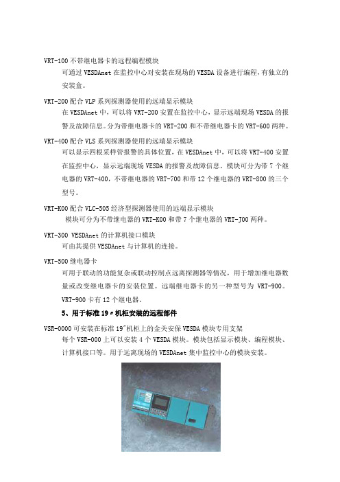
VRT-100不带继电器卡的远程编程模块可通过VESDAnet在监控中心对安装在现场的VESDA设备进行编程,有独立的安装盒。
VRT-200配合VLP系列探测器使用的远端显示模块在VESDAnet中,可以将VRT-200安置在监控中心,显示远端现场VESDA的报警及故障信息。
分为带继电器卡的VRT-200和不带继电器卡的VRT-600两种。
VRT-400配合VLS系列探测器使用的远端显示模块可以显示四根采样管报警的具体位置,在VESDAnet中,可以将VRT-400安置在监控中心,显示远端现场VESDA的报警及故障信息。
模块可分为带7个继电器的VRT-400,不带继电器的VRT-700和带12个继电器的VRT-800的三个型号。
VRT-K00配合VLC-505经济型探测器使用的远端显示模块模块可分为不带继电器的VRT-K00和带7个继电器的VRT-J00两种。
VRT-300 VESDAnet的计算机接口模块可由其提供VESDAnet与计算机的连接。
VRT-500继电器卡可用于联动的功能复杂或联动控制点远离探测器等情况,用于增加继电器数量或改变继电器卡的安装位置。
远端继电器卡的另一种型号为VRT-900。
VRT-900卡有12个继电器。
5、用于标准19〃机柜安装的远程部件VSR-0000可安装在标准19"机柜上的金关安保VESDA模块专用支架每个VSR-000上可以安装4个VESDA模块。
模块包括显示模块、编程模块、计算机接口等。
用于远离现场的VESDAnet集中监控中心的模块安装。
6、金关安保VESDA计算机通讯模块VHX-0200 VESDAnet与计算机之间的通讯模块提供RS-232接口。
利用V-Config及VSM3软件可对VESDA进行编程及报警显示等多种功能,必须配合专用软件使用。
VHX-0300 VESDAnet与计算机之间的通讯模块提供RS-232接口及开放的通讯协议。
可用于将VESDA接入其它监控系统及开发新的VESDA集中监控系统。
Linksys RVS4000 说明书

TheGreenBow IPSec VPN ClientConfiguration GuideLinksys RVS4000WebSite: Contact: ***********************Table of contents1 Introduction (3)1.1 Goal of this document (3)1.2 VPN Network topology (3)1.3 Linksys RVS4000 Restrictions (3)1.4 Linksys RVS4000 VPN Gateway (3)1.5 Linksys RVS4000 VPN Gateway product info (3)2 Linksys RVS4000 VPN configuration (4)3 TheGreenBow IPSec VPN Client configuration (6)3.1 VPN Client Phase 1 (IKE) Configuration (6)3.2 VPN Client Phase 2 (IPSec) Configuration (7)3.3 Open IPSec VPN tunnels (7)4 Tools in case of trouble (8)4.1 A good network analyser: Wireshark (8)5 VPN IPSec Troubleshooting (9)5.1 « PAYLOAD MALFORMED» error (wrong Phase 1 [SA]) (9)5.2 « INVALID COOKIE » error (9)5.3 « no keystate » error (9)5.4 « received remote ID other than expected » error (9)5.5 « NO PROPOSAL CHOSEN » error (10)5.6 « INVALID ID INFORMATION » error (10)5.7 I clicked on “Open tunnel”, but nothing happens. (10)5.8 The VPN tunnel is up but I can’t ping ! (10)6 Contacts (12)1 Introduction1.1 Goal of this documentThis configuration guide describes how to configure TheGreenBow IPSec VPN Client with a Linksys RVS4000 nksys RVS4000 VPN router.1.2 VPN Network topologyIn our VPN network example (diagram hereafter), we will connect TheGreenBow IPSec VPN Client to the LAN behind the Linksys RVS4000 router. The VPN client is connected to the Internet with a DSL connection or through a LAN. All the addresses in this document are given for example purpose.IPSec VPN Client192.168.1.3IPSec VPN Client (as seen on the LAN) 192.168.20.331.3 Linksys RVS4000 RestrictionsNo known restrictions.1.4 Linksys RVS4000 VPN GatewayOur tests and VPN configuration have been conducted with Linksys RVS4000 firmware release 1.1.14.1.5 Linksys RVS4000 VPN Gateway product infoIt is critical that users find all necessary information about Linksys RVS4000 VPN Gateway. All product info, User Guide and knowledge base for the Linksys RVS4000 VPN Gateway can be found on the Linksys RVS4000 website: .Linksys RVS4000Product page/servlet/Satellite?c=L_Product_C2&childpagename=US%2FLayo ut&pagename=Linksys%2FCommon%2FVisitorWrapper&cid=11504909152782Linksys RVS4000 VPN configurationThis section describes how to build an IPSec VPN configuration with your Linksys RVS4000 VPN router.Once connected to your Linksys RVS4000 VPN gateway, you must select “VPN” and “VPN Pass Through” tabs.2.1 Configure Linksys RVS4000to allow IPSEC Pass ThroughNote: Configure IPSec Pass Through for good measure unless you know better or care to experiment.Enable the ‘IPSec Pass Through’ and ‘Save Settings’.2.2 Create an IPSec VPN tunnel in Linksys RVS4000To configure the IPSec Tunnel in Linksys RVS4000 VPN gateway, you must select “VPN” and “IPSec VPN” tabs. Configure as mentioned in the below figure and save settings.The Remote security gateway is set to IP by DNS Resolved and mentioned as 0.0.0.0. It is same as allowing any gateway because we will be having dynamic IP in VPN Client computer.The Remote security group is mentioned as 192.168.20.33. It is the VPN Client IP address for this tunnel.Click ‘Save Settings’ and create a new VPN tunnel settings for another user by changing the tunnel name on top the windows below.3TheGreenBow IPSec VPN Client configurationThis section describes the required configuration to connect to a Linksys RVS4000 VPN router.To download the latest release of TheGreenBow IPSec VPN Client software, please go to /vpn_down.html.3.1VPN Client Phase 1 (IKE) ConfigurationPhase 1 configurationYou may use either Preshared, Certificates, USB Tokens or X-Auth for User Authentication with the Linksys RVS4000 router. This configuration is one example of can be accomplished in term of User Authentication. You may want to refer to either the Linksys RVS4000 router user guide or TheGreenBow IPSec VPN Client User Guide for more details on User Authentication options.3.2VPN Client Phase 2 (IPSec) ConfigurationPhase 2 Configuration3.3Open IPSec VPN tunnelsOnce both Linksys RVS4000 router and TheGreenBow IPSec VPN Client software have been configured accordingly, you are ready to open VPN tunnels. First make sure you enable your firewall with IPSec traffic.1. Click on "Save & Apply" to take into account all modifications we've made on your VPN Client configuration2. Click on "Open Tunnel", or generate traffic that will automatically open a secure IPSec VPN Tunnel (e.g. ping, IE browser)3. Select "Connections" to see opened VPN Tunnels4. Select "Console" if you want to access to the IPSec VPN logs and adjust filters to display less IPSec messaging. The following example shows a successful connection between TheGreenBow IPSec VPN Client and a Linksys RVS4000 VPN router.4Tools in case of troubleConfiguring an IPSec VPN tunnel can be a hard task. One missing parameter can prevent a VPN connection from being established. Some tools are available to find source of troubles during a VPN establishment.4.1 A good network analyser: WiresharkWireshark is a free software that can be used for packet and traffic analysis. It shows IP or TCP packets received on a network card. This tool is available on website . It can be used to follow protocol exchange between two devices. For installation and use details, read its specific documentation (/docs/).5VPN IPSec Troubleshooting5.1« PAYLOAD MALFORMED» error (wrong Phase 1 [SA])114920 Default (SA CNXVPN1-P1) SEND phase 1 Main Mode [SA][VID]114920 Default (SA CNXVPN1-P1) RECV phase 1 Main Mode [NOTIFY]114920 Default exchange_run: exchange_validate failed114920 Default dropped message from 195.100.205.114 port 500 due to notification type PAYLOAD_MALFORMED114920 Default SEND Informational [NOTIFY] with PAYLOAD_MALFORMED errorIf you have an « PAYLOAD MALFORMED » error you might have a wrong Phase 1 [SA], check if the encryption algorithms are the same on each side of the VPN tunnel.5.2« INVALID COOKIE » error115933 Default message_recv: invalid cookie(s) 5918ca0c2634288f 7364e3e486e49105 115933 Default dropped message from 195.100.205.114 port 500 due to notification type INVALID_COOKIE115933 Default SEND Informational [NOTIFY] with INVALID_COOKIE errorIf you have an « INVALID COOKIE » error, it means that one of the endpoint is using a SA that is no more in use. Reset the VPN connection on each side.5.3« no keystate » error115315 Default (SA CNXVPN1-P1) SEND phase 1 Main Mode [SA][VID]115317 Default (SA CNXVPN1-P1) RECV phase 1 Main Mode [SA][VID]115317 Default (SA CNXVPN1-P1) SEND phase 1 Main Mode [KEY][NONCE]115319 Default (SA CNXVPN1-P1) RECV phase 1 Main Mode [KEY][NONCE]115319 Default (SA CNXVPN1-P1) SEND phase 1 Main Mode [ID][HASH][NOTIFY]115319 Default ipsec_get_keystate: no keystate in ISAKMP SA 00B57C50Check if the preshared key is correct or if the local ID is correct (see « Advanced » button). You should have more information in the remote endpoint logs.5.4« received remote ID other than expected » error120348 Default (SA CNXVPN1-P1) SEND phase 1 Main Mode [SA][VID]120349 Default (SA CNXVPN1-P1) RECV phase 1 Main Mode [SA][VID]120349 Default (SA CNXVPN1-P1) SEND phase 1 Main Mode [KEY][NONCE]120351 Default (SA CNXVPN1-P1) RECV phase 1 Main Mode [KEY][NONCE]120351 Default (SA CNXVPN1-P1) SEND phase 1 Main Mode [ID][HASH][NOTIFY]120351 Default (SA CNXVPN1-P1) RECV phase 1 Main Mode [ID][HASH][NOTIFY]120351 Default ike_phase_1_recv_ID: received remote ID other than expected **********************The « Remote ID » value (see « Advanced » Button) does not match what the remote endpoint is expected.5.5« NO PROPOSAL CHOSEN » error115911 Default (SA CNXVPN1-P1) SEND phase 1 Main Mode [SA][VID]115913 Default (SA CNXVPN1-P1) RECV phase 1 Main Mode [SA][VID]115913 Default (SA CNXVPN1-P1) SEND phase 1 Main Mode [KEY][NONCE]115915 Default (SA CNXVPN1-P1) RECV phase 1 Main Mode [KEY][NONCE]115915 Default (SA CNXVPN1-P1) SEND phase 1 Main Mode [ID][HASH][NOTIFY]115915 Default (SA CNXVPN1-P1) RECV phase 1 Main Mode [ID][HASH][NOTIFY]115915 Default phase 1 done: initiator id c364cd70: 195.100.205.112, responder idc364cd72: 195.100.205.114, src: 195.100.205.112 dst: 195.100.205.114115915 Default (SA CNXVPN1-CNXVPN1-P2) SEND phase 2 Quick Mode [SA][KEY][ID][HASH][NONCE]115915 Default RECV Informational [HASH][NOTIFY] with NO_PROPOSAL_CHOSEN error115915 Default RECV Informational [HASH][DEL]115915 Default CNXVPN1-P1 deletedIf you have an « NO PROPOSAL CHOSEN » error, check that the « Phase 2 » encryption algorithms are the same on each side of the VPN Tunnel.Check « Phase 1 » algorithms if you have this:115911 Default (SA CNXVPN1-P1) SEND phase 1 Main Mode [SA][VID]115911 Default RECV Informational [NOTIFY] with NO_PROPOSAL_CHOSEN error5.6« INVALID ID INFORMATION » error122623 Default (SA CNXVPN1-P1) SEND phase 1 Main Mode [SA][VID]122625 Default (SA CNXVPN1-P1) RECV phase 1 Main Mode [SA][VID]122625 Default (SA CNXVPN1-P1) SEND phase 1 Main Mode [KEY][NONCE]122626 Default (SA CNXVPN1-P1) RECV phase 1 Main Mode [KEY][NONCE]122626 Default (SA CNXVPN1-P1) SEND phase 1 Main Mode [ID][HASH][NOTIFY]122626 Default (SA CNXVPN1-P1) RECV phase 1 Main Mode [ID][HASH][NOTIFY]122626 Default phase 1 done: initiator id c364cd70: 195.100.205.112, responder idc364cd72: 195.100.205.114, src: 195.100.205.112 dst: 195.100.205.114122626 Default (SA CNXVPN1-CNXVPN1-P2) SEND phase 2 Quick Mode [SA][KEY][ID][HASH][NONCE]122626 Default RECV Informational [HASH][NOTIFY] with INVALID_ID_INFORMATION error 122626 Default RECV Informational [HASH][DEL]122626 Default CNXVPN1-P1 deletedIf you have an « INVALID ID INFORMATION » error, check if « Phase 2 » ID (local address and network address) is correct and match what is expected by the remote endpoint.Check also ID type (“Subnet address” and “Single address”). If network mask is not check, you are using a IPV4_ADDR type (and not a IPV4_SUBNET type).5.7I clicked on “Open tunnel”, but nothing happens.Read logs of each VPN tunnel endpoint. IKE requests can be dropped by firewalls. An IPSec Client uses UDP port 500 and protocol ESP (protocol 50).5.8The VPN tunnel is up but I can’t ping !If the VPN tunnel is up, but you still cannot ping the remote LAN, here are a few guidelines:•Check Phase 2 settings: VPN Client address and Remote LAN address. Usually, VPN Client IP address should not belong to the remote LAN subnet•Once VPN tunnel is up, packets are sent with ESP protocol. This protocol can be blocked by firewall.Check that every device between the client and the VPN server does accept ESP•Check your VPN server logs. Packets can be dropped by one of its firewall rules.•Check your ISP support ESP•If you still cannot ping, follow ICMP traffic on VPN server LAN interface and on LAN computer interface (with Wireshark for example). You will have an indication that encryption works.•Check the “default gateway” value in VPN Server LAN. A target on your remote LAN can receive pings but does not answer because there is a no “Default gateway” setting.•You cannot access to the computers in the LAN by their name. You must specify their IP address inside the LAN.•We recommend you to install Wireshark () on one of your target computer. You can check that your pings arrive inside the LAN.6ContactsNews and updates on TheGreenBow web site: Technical support by email at ***********************Sales contacts by email at *********************。
赛米控丹佛斯 SEMITRANS IGBT模块 SKM400GB12T4 数据表

SEMITRANS ®3Fast IGBT4 ModulesSKM400GB12T4Features•IGBT4 = 4. generation fast trench IGBT (Infineon)•CAL4 = Soft switching 4. generation CAL-diode•Isolated copper baseplate using DBC technology (Direct Bonded Copper) •Increased power cycling capability •With integrated gate resistor•For higher switching frequenzies up to 20kHz•UL recognized, file no. E63532Typical Applications*•AC inverter drives •UPS•Electronic welders at fsw up to 20 kHzRemarks•Case temperature limited to T c = 125°C max.•Recommended T op = -40 ... +150°C •Product reliability results valid for T j = 150°CAbsolute Maximum Ratings SymbolConditions Values UnitIGBT V CES T j =25°C 1200V I C T j =175°CT c =25°C 616A T c =80°C474A I Cnom 400A I CRMI CRM = 3xI Cnom 1200A V GES -20...20V t psc V CC =800V V GE ≤ 15V V CES ≤ 1200VT j =150°C10µs T j-40...175°C Inverse diode I F T j =175°CT c =25°C 440A T c =80°C 329A I Fnom400A I FRM I FRM = 3xI Fnom1200A I FSM t p =10ms, sin 180°, T j =25°C1980A T j -40 (175)°C Module I t(RMS)T terminal =80°C500A T stg -40...125°C V isolAC sinus 50 Hz, t =1min4000VCharacteristics SymbolConditions min.typ.max.UnitIGBT V CE(sat)I C =400A V GE =15V chiplevel T j =25°C 1.80 2.05V T j =150°C 2.20 2.40V V CE0chiplevel T j =25°C 0.80.9V T j =150°C 0.70.8V r CE V GE =15V chiplevel T j =25°C 2.50 2.88m ΩT j =150°C3.754.00m ΩV GE(th)V GE =V CE , I C =15.2mA55.86.5V I CES V GE =0V V CE =1200V T j =25°C 5mA T j =150°C mA C ies V CE =25V V GE =0Vf =1MHz 24.6nF C oes f =1MHz 1.62nF C res f =1MHz1.38nF Q G V GE =- 8 V...+ 15 V 2260nC R Gint T j =25°C 1.9Ωt d(on)V CC =600V I C =400A V GE =±15V R G on =1ΩR G off =1Ωdi/dt on =9700A/µs di/dt off =4300A/µs T j =150°C 220ns t r T j =150°C 47ns E on T j =150°C 33mJ t d(off)T j =150°C 505ns t f T j =150°C 78ns E off T j =150°C 42mJ R th(j-c)per IGBT0.072K/WCharacteristics SymbolConditionsmin.typ.max.UnitInverse diodeV F = V EC I F =400AV GE =0V chiplevelT j =25°C 2.20 2.52V T j =150°C 2.15 2.47V V F0chiplevel T j =25°C 1.3 1.5V T j =150°C 0.9 1.1V r FchiplevelT j =25°C 2.3 2.5m ΩT j =150°C3.1 3.4m ΩI RRM I F =400A di/dt off =8800A/µs V GE =±15VV CC =600VT j =150°C 450A Q rr T j=150°C68µC E rr T j =150°C 30.5mJR th(j-c)per diode0.14K/W Module L CE 1520nH R CC'+EE'terminal-chip T C =25°C 0.25m ΩT C =125°C0.5m ΩR th(c-s)per module 0.020.038K/W M s to heat sink M635Nm M t to terminals M62.55Nm Nm w325gSEMITRANS ® 3Fast IGBT4 ModulesSKM400GB12T4Features•IGBT4 = 4. generation fast trench IGBT (Infineon)•CAL4 = Soft switching 4. generation CAL-diode•Isolated copper baseplate using DBC technology (Direct Bonded Copper) •Increased power cycling capability •With integrated gate resistor•For higher switching frequenzies up to 20kHz•UL recognized, file no. E63532Typical Applications*•AC inverter drives •UPS•Electronic welders at fsw up to 20 kHzRemarks•Case temperature limited to T c = 125°C max.•Recommended T op = -40 ... +150°C •Product reliability results valid for T j = 150°CFig. 1: Typ. output characteristic, inclusive R CC'+ EE'Fig. 2: Rated current vs. temperature I C = f (T C )Fig. 3: Typ. turn-on /-off energy = f (I C )Fig. 4: Typ. turn-on /-off energy = f (R G )Fig. 5: Typ. transfer characteristic Fig. 6: Typ. gate charge characteristicFig. 7: Typ. switching times vs. I C Fig. 8: Typ. switching times vs. gate resistor R GFig. 9: Transient thermal impedance Fig. 10: Typ. CAL diode forward charact., incl. R CC'+ EE'Fig. 11: CAL diode peak reverse recovery current Fig. 12: Typ. CAL diode peak reverse recovery chargeThis is an electrostatic discharge sensitive device (ESDS), international standard IEC 60747-1, Chapter IX* The specifications of our components may not be considered as an assurance of component characteristics. Components have to be tested for the respective application. Adjustments may be necessary. The use of SEMIKRON products in life support appliances and systems is subject to prior specification and written approval by SEMIKRON. We therefore strongly recommend prior consultation of our staff.。
施耐德自动化产品介绍

ሏႜ ᆫࣅ
ፌׂิࢅీׂࣅٷၳ୲ ॔੦߾ሏႜጒLjۨᆫ ံपਦ֧փీࠕेᅜํแԍኤ߾ڟڥᆶၳڦ੦
具有规模可延展性、灵活性、集成性、协同性四大特性 规模可延展性 协同性
适应系统改造和升级需求
灵活性
您的系统对于我们来说 都是独一无二的 支持各种客户需要的系统 构架,可以实现从单站点 控制,多站点控制,分布 式控制,集中式控制,离 散控制,过程控制,安全 控制到批量控制的多种控 制方式。
3
Modicon Quantum-性能卓越的高端 自动化平台
概述
Unity Pro
a Socollaborative software
Modicon Quantum 是 PLC 的发明者 Modicon 推出的高端自动化平 台,一经推出,就以其无与伦比的可靠性和稳定性,在全球范围内, 特别是中国市场上取得了巨大的成功。2005 年初施耐德电气推出全 新的 Unity 自动化平台,作为该平台的重要组成部分之一,Modicon Quantum 获得了全面的升级。 作为工厂自动化和过程自动化领域最理想的高端自动化平台, Modicon Quantum 广泛应用于以下领域:
海事组织的认证:
■ 美国 ABS 认证 ■ 法国 BV 认证 ■ 挪威 DNV 认证 ■ 德国 GL 认证 ■ CEI GOST 认证 ■ 英国 LR 认证 ■ CIS 的 RRS 认证
等
4
全面升级的 CPU 的技术特征
随着 Unity 自动化平台的发布, Modicon Quantum 推出 6 款基于 Unity 平台的 CPU。这些 CPU 在指令执行速度,内存容量,通讯性能 和热备性能等方面获得了巨大的突破:
南瑞新能源及电力领域产品

新能源发电供货指南前言电力是现代人类文明社会的必需品,然而煤炭、石油等有限资源日益紧张,环境污染问题日益严峻。
太阳能和风能以及其他新能源作为最具潜力的可再生能源,因其储量的无限性、存在的普遍性、利用的清洁性以及实用的经济性,越来越被人们所青睐。
大力发展风电、光伏产业,积极开发清洁能源,在全球范围得到了空前重视,已成为各国可持续发展战略的重要组成部分。
风能、太阳能具有利用固有能量密度低、随机性、不稳定性和分布不均匀的特点。
且风电、光伏系统要求安全可靠、稳定运行、处理电气故障的快速性与准确性以及故障之后的及时恢复。
近两年,国家在草原、海岛等边远地区发展分布式电源、智能微电网、户用新能源发电,成效逐步显现。
微电网系统具有资源分散、项目容量小、用户类型多样的特点,需保证微电网系统安全、稳定、经济运行。
本资料是根据我公司多年来的研发、工程实施、售后服务等方面的丰富经验,针对风电、光伏、以及分布式电源、微电网系统、户用新能源的上述特点,把我公司的产品编辑整理,供广大用户根据自己的实际需要选择使用。
本供货指南所列产品主要为风电、光伏发电的不同环节的自动化装置与系统以及分布式电源、智能微电网、户用新能源的自动化装置与系统。
目录前言 (2)目录 (3)一、解决方案 (5)1、风电场自动化系统解决方案 (6)2、光伏电站自动化系统解决方案 (8)3、分布式电源解决方案 (9)4、微电网解决方案 (10)5、户用新能源发电解决方案 (10)二、系统类产品 (11)1、新能源远程综合监控系统 (11)2、NSW6000风电场远程监控系统 (12)3、NSW3000风电场综合监控系统 (15)4、NSW3100风电场功率控制系统 (17)5、NSF3100风电功率预测系统 (18)6、NSS6000光伏电站远程监控系统 (19)7、NSS3000光伏电站综合监控系统 (21)8、NSS3100光伏电站功率控制系统 (22)9、NSF3200光伏发电功率预测系统 (24)10、NSV2000视频监控系统 (25)11、WFBX多功能微机防误操作闭锁系统 (27)12、DGM8000分布式电源接入控制系统 (29)13、NMC1000微电网能量管理系统 (30)14、NMC8921户用新能源离网发电系统 (31)15、NMC8922户用新能源并/离网发电系统 (32)16、NMC8923户用新能源联合供能系统 (33)三、装置类产品 (35)1、NSC2200E通信管理装置 (35)2、NSC681测控装置 (36)3、NSR2000故障录波测距装置 (38)4、NSR-3XX系列高压保护装置 (39)5、NSR-3600系列保护测控装置 (50)6、NSP7XX系列保护测控装置 (54)7、NSP551低压保护测控装置 (62)8、NES5412风机变流器 (63)9、NES5411风机变流器 (63)10、NES5430系列风电机组主控系统 (65)11、NES5420系列风电机组变桨系统 (67)12、NZD651系列箱变保护测控装置 (68)13、NSP787-P防逆流装置 (69)14、进口测控装置6MD系列 (70)15、进口线路差动保护装置7SD系列 (72)16、7SJ62多功能保护测控装置 (73)17、7SJ68多功能保护测控装置(中文显示).........................错误!未定义书签。
时代新纪元科技集团 TVF7000 系列 高性能无速度传感器矢量控制变频器 说明书

矢量控制变频器
TVF7000 系列 高性能无速度传感器矢量控制变频器
用 户 手 册
产品版本 手册版本
V1.0 V1.0
时代新纪元科技集团有限公司
前 言
时代TVF系列变频器的用户朋友:
您好! 感谢您选用时代TVF7000系列矢量变频器。 7000系列矢量变频器是时代公司开发的真正的电流矢量控制 变频器。体积小巧,功能齐全,性能优越,操作简便。 7000系列矢量控制变频器同时具有电流矢量和V/F两种控制方 式,用户可根据具体情况进行选择,本产品能够适用于各种高性 能要求的应用场合。 7000系列矢量变频器安装操作虽然简单, 但误操作可能会引起 意外事故,缩短变频器寿命,降低其性能,因此在使用前请务必 仔细熟读使用手册,掌握正确使用方法并请妥善保管使用手册, 以便能长久使用。 如果在使用中有不明之处, 或者未能发挥其优良性能时,请仔 细参阅使用手册或与公司联系,将有助于正确使用变频器。
述 ..........................................................................................................6
本手册使用指南 .................................................................................................... 6 开箱检查 ................................................................................................................ 6 产品型号 ................................................................................................................ 6 产品的搬运 ............................................................................................................ 7 产品的保存 ............................................................................................................ 7 产品的保修 ............................................................................................................ 7
实时自动化460ESSC-N2E EtherNet IP扫描器与S7 PLC之间的数据传输解决方案说

460ESSC-N2ECONTACT US!1-800-249-1612 Real Time Automation GatewaysA Solution, A Philosophy, the RTA Way. We understand the long hours spent on a factory floor and the pressure to keep a line running and product flowing. That’s how Real Time Automation came to be. Youwant easy-to-use solutions where the hardest part is to open the box. You need customer support secondto none. If you get all that and a fun customer experience all the better. Thirty years later, our mission remains the same: To move your data where you need it, when you need it, and how you need it.Get Your EtherNet/IP Scanner Connected Directly to Your S7 PLCThe 460ESSC moves data between an EtherNet/IP scanner device and up to five S7 PLCs. Move data from your EtherNet/IP scanner device to S7 PLCs like the S7 300/400/1200/1500.How Do I Use the 460ESSC-N2E in My Application?You allocate two memory blocks in your S7 PLC. One area is a user-defined set of output addresses sending data to your EtherNet/IP scanner. The other is input only data receiving data from your EtherNet/IP scanner.It’s really that simple. Need to modify your data as it passes from one protocol to the other? No problem. Each data mapping you apply can be modified with up to three mathematic functions. Add 4 to a value, multiply by 4 and divide by 10 with ease.Why Use Real Time Automation as a Gateway Supplier?While there are certainly other companies offering protocol gateways, there is no one who provides the level of support and service that you receive from RTA. When you call, a live person answers the phone. When you talk with sales, you will get honest answers and recommendations. When you get support, it is from an engineer who had a hand in the product’s development, and support doesn’t require a ticket or 24-hour wait.FEATURES •Fully configurable EtherNet/IP adapter •Supports up To 480bytes of input and 480 bytes of output data•Supports connectionsto five Siemens S7 PLCs •Up to 150 read and 150 write requests per connection•Effortless BrowserBased Configuration, no programming software is required•Simple data translationallows you tomanipulate data as it passes betweenprotocols•Guaranteed Stock• 5-Year HardwareWarrantyReal Time Automation, Inc.************************** - 1-800-249-1612Made in theU.S.A.Always InStockReady toShipExpertSupportEtherNet/IP Adapter Operation Mode Class 1 I/O AdapterMessage Support Implicit Class 1 Cyclic I/O, Explicit Class 3 and UCMM Supported Data TypesBIT8,16 & 32; INT8, 16, 32 & 64; UINT8,16, 32 & 64; Float & Double Maximum EtherNet/IP Scanner Devices Up to 10 can listen, only 1 can write I/O Maximum Data Supported Up to 480 bytes in each direction Maximum IO Scan Rate 20 msecS7 Client PLC SupportS7 300/400/1200/1500 Maximum Number of PLCs Supported5 Maximum Number of Inputs/Outputs per PLC 150 Maximum Number of Bytes per Scan Line 400Memory Area Access Input (I), Output (Q), and Data Block( DB)Supported Data Types8 Bit Int, 16 Bit Int, 32 Bit Int, 32 Bit Float, Bool and Char Array INCLUDED WITH GATEWAY 3’ power cable with flying leads5-year hardware warrantyIPSetup software – automatically locates RTA gateway on the networkUnlimited firmware feature upgrades for lifeCAT5 crossover cable for direct connection to PC during programming Complete, unlimited access to our industry leading support staff ManualELECTRICAL / ENVIRONMENTALDC Input Voltage 12-24 VDC .Maximum Baud Rate 115K baud Operating Temperature -40 C to 85 CCertificationRoHS-Compliant, UL, CUL, CE Approvals, Class I Div 2ENCLOSURE / HARDWARE Size 5.40" x 3.83" x 1.19" Weight 7.6 oz Enclosure Type Anodized Aluminum Mounting Din rail or panel mount LEDs Power LED & 2 general purpose LEDs on side GATEWAY FEATURES & FUNCTIONSAlarming Set <, <=, >, >=, ==, !=, and change-of-state ruleson any data moving through the gateway. If alarmrule is triggered an email notification can be sent. Gateway SecurityYou can configure up to 9 different users access todiagnostic and configuration screens. Translation TableAllows for data manipulation during protocol translation. Scaling and other data format changes can occur in the gateway.Status and CountersProtocol specific status, counters, and error messages are accessible within the gateway’s diagnostics page. They can also be delivered to a connected device.NOT EXACTLY WHAT YOU WERE LOOKING FOR? Real Time Automation offers a full line of gateway products. Give us a call at 1-800-249-1612. Or, check out a listing at/products . We also offercustomizations for unique applications.Diagnostic Logging PageAllows users to see and log start up sequences, protocol specific messages & error messages.CATALOG # DESCRIPTION460ESSC-N2EConnects an EtherNet/IP scanner with as many as five S7 PLCs。
- 1、下载文档前请自行甄别文档内容的完整性,平台不提供额外的编辑、内容补充、找答案等附加服务。
- 2、"仅部分预览"的文档,不可在线预览部分如存在完整性等问题,可反馈申请退款(可完整预览的文档不适用该条件!)。
- 3、如文档侵犯您的权益,请联系客服反馈,我们会尽快为您处理(人工客服工作时间:9:00-18:30)。
Package Contents
• User Guide on CD-ROM • Network Cable • Power Adapter • Stands • Registration Card • Quick Install Guide
Congratulations! The installation of the Router is complete.
NOTE: For more advanced settings and securser Guide on the RVS4000 CD-ROM.
G Restart or power on your PCs
so they can obtain the router's new settings.
H Test the setup by opening
your web browser from any computer and entering / registration.
tab.
D If requested by your ISP
C
(usually cable ISPs), complete
the Host Name and Domain
Name fields, and the MTU and
MTU Size fields. Otherwise,
leave the defaults.
PPPoE: If you are connecting through PPPoE, select PPPoE from the drop-down menu. Complete the User Name and Password fields.
PPTP: PPTP is a service used in Europe only. If you are using a PPTP connection, check with your ISP for the necessary setup information.
L2TP. L2TP is used mostly in Europe. Check with your ISP for the necessary setup information.
F When you are finished
entering your Internet connection settings, click the Save Settings button to save your changes.
A Open your web browser. Enter
http://192.168.1.1 in its
Address field. Press the Enter
key.
A
B A password request screen
will appear. Enter the default
user name and password,
installation is now complete.
NOTE: Before setting up the Router, make sure your PCs are configured to obtain an IP (or TCP/IP) address automatically from the Router.
admin, in lowercase letters in
the User Name and Password
fields. (For added security, you
should later set a new
password, using the
Administration tab’s
Management screen of the
B Make sure that all of your
network’s hardware is powered off, including the Router, PCs, and cable or DSL modem.
C Connect one end of an
Ethernet network cable to one
Heartbeat Signal
L2TP
For additional information or troubleshooting help, refer to the User Guide on the CD-ROM. You can also call or e-mail for further support. 24-hour Technical Support
network devices to the Router.
BUSINESS SERIES
E Connect a different Ethernet
network cable from your
cable or DSL modem to the
Internet port on the Router’s
H The Power and Internet LEDs
G
on the front panel will light up
green as soon as the power
adapter is connected
properly.
I Power on the PCs.
J The Router’s hardware
Automatic - DHCP Static IP PPPoE PPTP
Heartbeat Signal. Heartbeat Signal is used primarily in Australia. Check with your ISP for the necessary setup information.
800-326-7114 (toll-free from US or Canada) E-mail Support support@ Website or RMA (Return Merchandise Authorization) /support FTP Site ftp:// Sales Information 800-546-5797 (800-LINKSYS) Linksys is a registered trademark or trademark of Cisco Systems, Inc. and/or its affiliates in the U.S. and certain other countries. Copyright © 2006 Cisco Systems, Inc. All rights reserved.
back panel.
E
F Power on the cable or DSL
modem.
G Connect the power adapter to
the Router’s Power port, and
then plug the other end into
an electrical outlet.
Static IP: If your ISP assigns you a static IP address, select Static IP from the drop-down menu. Complete the Internet IP Address, Subnet Mask, Default Gateway, and DNS fields. You need to enter at least one DNS address.
RVS4000-QI-60524NC RR
B
web-based utility). Then click
the OK button.
C The web-based utility will
appear with the Setup tab and
IP Mode selected. Click on the
WAN option under the Setup
E For the Connection Type
setting, six connection types are offered through the drop-down menu. Each Setup screen and available features will vary depending on which connection type you select.
of the LAN ports (labeled 1-4)
QUICK INSTALLATION
on the back of the Router, and
the other end to an Ethernet
C
port on a PC.
D Repeat step C to connect
more PCs, a switch, or other
2 Configure the Router
These instructions will show you how to configure the Router. You only need to configure the Router once using any computer you have set up.
ModeMlodNeMloNo.odR.elVNSo.4000
WIRED
1 Connect the Router
A Before you begin, make sure
that you have the setup information for your specific type of Internet connection. The installation technician from your ISP should have left this information with you after installing your broadband connection. If not, you can call your ISP to request the settings.
