机械毕业设计外文翻译---纸浆和造纸行业中的无水氨压力容器
制浆造纸专业词汇中英文对照表

制浆造纸专业词汇中英文对照表●Acceleration加速度●Accepted stock良浆●Acid-resistant lining防酸衬里●Actuating开动●Actuator●Actuator执行器●Additive添加剂●Adhesive tape胶布●Adhesive黏合剂Adjust plate调节块●Adjust plate调节块●Adjuster调节器●Adjustinant screw调平螺栓Adjusting plain调平垫片●Adjustment 调整Agitators and unit price搅拌器及分项价格清单●Agitator搅拌机●Agitator推进器●Agitator推进器●Air bells loaded headbox气垫式压力流浆箱●Air compression room空压机房Air exchangerAir exhauster排风机Air feeder 送风机Air filtration paperAir float table汽托堆纸台Air float气垫●Air permeability●air pressure gauge气压表●Air purge●Air purge清洁Air regulator 空气调节器●Air resistence透气阻力Air spring气垫●Air tube气源管●Air turn空气转向器●Air-knife coater 气刀涂布机●Air-tight test●Airtight密封的●Alarm point报警限位Alignment angle●Alignment调整,校直,对准●Alloy羊角滑钩●Alum 硫酸铝●American old corrugated container(AOCC)美国废旧瓦楞纸箱●amplifier card放大器电路插板●Anchor block地块,地脚蜡台●Anchor bolts地脚螺栓●Anionic trash catcher (ATC)阴离子垃圾捕捉剂●Anti jamming system防堵筛装置●Anti-corrosive agent防锈剂●Antistatic bars抗静电装置●Anti-tarnish paper防锈纸●Anti-wear抗磨的●Anto centralism device●Appendix two附件二●Applicator roll涂布辊●Approach system流送系统●Assist 辅助Assy frame 机架装配●Attenuate tank缓冲罐●Attenuator tank缓冲罐●Auto centralism device自动对中装置●Automatic pallet exit自动垛纸装置●Automatic pallet exit自动垛纸装置Automatic pick-up自动递纸装置,引纸Automatic work●Automation 自动化Auxiliary absorber辅助吸收器●Auxiliary辅助的●Axial fan轴流通风机●Back and forth来回,前后●Back-flushing反冲●Backing roll背辊●Ball valve●Ball valve球阀Base paper原纸●Base plateBase sheet原纸●Basement●Basis weight 定量●Basis weight基本重量●Batch 间歇法●Bearing housing齿轮箱●Bearing to be connected to the circulation lubericant轴承稀循环油润滑●Beating打浆●Bellows●Belt change equipment●Belt靴套●Bent-blade designs弯刀型设计●Bimetallic strip双金属片●Binder胶黏剂●Black liquor黑液●Blade coater 刮刀涂布机●Blades刀片●Blanket毡●Blind-drilled receptor roll盲孔纳水辊●Blow box真空箱●Blow pipe喷放管●Blower valve鼓风机阀●Blower风机●Board machine●BOM料单●Bone dry weight绝干量●Bore diameter of outer ring 外环孔径,外环内径Bottom roll 底辊●Bound water zone结合水区●Boundary layer●Boundary layer 底层●Boundary layer边界●Bound范围●Bow screen弧形筛●Bowl盘●Boxboard cutting箱纸板裁片●Box-liner paper纸盒衬里箱●Bracket●BracketBracket●Brake control刹车控制●Break-back roll●Bridge model架桥模型●Brightening增白Brightness白度,亮度Brilliance明亮度●Buffer tank缓冲槽●Burst耐破度●Cabinet 开关柜●Cabinet、cubicle开关柜●Cabinet室,盒,机壳●Calendar●Calendar rollCalendar roll压光辊●cantilever screw●cantilever切口,缺口,悬臂梁●Capacity●Carriage换辊小车●Casing 框,壳,包●Cast浇注,铸造Cationic demand(CD)阳离子需求●Caution小心●CD Labyrinth seal●Cell小室●Centre line中心线●Centrifugal forces离心力Centrifugal pump离心泵●ceramics陶瓷●Change of deckle更换定边带●Cheek脸Chemical additives化学助剂●Chill water tank冷冻水缓冲槽●Chopper fan 纸边风机●Chopper-fan纸边风机Clamp bar●Clamp bar版夹●Clamper减震器●Clamping bar夹杆●Clamp夹紧,固定●Cleaner●Cleaning agent清洁剂●Cleanliness class洁净等级●Cleanliness factors干净度●Cleanliness level●clearance gauge测隙规●Clearance间隙●Clearance间隙●Clearance净空,许可证,清理●Clearing water hydrants消防栓●Cloudy water浓白水●Clump浆块●Cluster setting分组装置●Clutch离合器●Coagulant凝合剂Coagulate凝结Coagulating agent凝结剂Coagulation凝结●Coanda effect附壁效应●Coated wttl白纸板●Coater●Coater and dryer=coadry●coil蛇管●Collector pipe集水管,集汽管●Column立柱●Column立柱●Compatibility兼容性●Compatible相容的●Compensated flow control valve带压力补偿的流量控制阀,调速阀●Compensated relief valve平衡溢流阀●Compensated roll调节辊,补偿辊Complement辅助●Conception思想,观念●Concrete●Condensate●Confidential机密的Conic section 锥部●Conic spring washer弹簧垫片●Connecting rodConneting block●Consignee●Consistency上浆浓度●Construction建设●Continuous running-in综合连续试运转●Control valve控制阀●Conversion table●Conveyor输送机●Conveyor输送机●Cooling water冷却水Copperplate base paper铜板原纸Copperplate paper铜版纸●Cord packing●Cord packing盘根●Core pusher推纸衬●Core slitter切纸芯装置●Corner roll角辊●Corresponding通讯,对应●Corrosion腐蚀●Corrosion侵蚀Coupling guards靠背轮罩●Coupling靠背轮Cradle木框●Crane●Crane equipment电动双梁桥式起重机CR-cover,negative crown覆面负中高辊●Cross beamCross direction●Cross going beam定距梁●Cross section横截面●Cross walkways横幅走台●Crow bar撬杠Cubicle开关柜●Cut-off blow●Cut-off blow●Cutting group横切单元●Cutting unit横切装置●Cyclone除尘器,离心机,分尘机●Cylinder●Cylinder thickener圆网浓缩机●Datum line基准线●Decenter沉降器●Defiberer●Defiberer疏解机●Deflection compensated rollDefoamer消泡剂●Delivery scope供货范围Detach from拆卸●Detachment●Dew point●Dewatering element change equipmentDewatering element change equipment换箱装置●Dewatering elements, alignment●Dial micrometer测微仪,千分刻度盘,厚度千分仪●Dilution screen稀释水压力筛●Dilution稀释●Dim. Basis weight基本名义克重●Dimension 尺寸,规格●directional control valve●Discharge卸下,放出●Dismounting: pressurized oil两侧轴承拆卸使用压力油●Dispersant分散剂Dispersant分散剂●Dispersing tank 分散槽●DoctorDoctor ventilator通风口,通风器Double gummed paper双胶纸,胶版纸,书写纸Down-run nozzleDrain hole放泄孔,排水孔●Drain valve ball泄压阀●Drain valve防水阀●Drainage foil\foil 案板,脱水板●Drain排干●Drain下水道,排水阀,消耗●Draw roll牵引辊●Draw roll牵引辊●Drawning●Drilling●Droplet separator雾气分离器●Drum sorter圆筒筛Dryer section●Drying cylinder烘缸●Duct导管,风管●Duplication ordisclosure●Dust container粉尘箱●Dust removal-fan除尘风机●Dust removing system除尘系统●Dynamic balancing 动平衡●Edge beam●Edge deck●Edge deck cheek nozzle●Edge边缘●Effective volume●Ejection air pump喷吸气泵●Ejection喷出,喷出物●Electrical hardware电气设备●Electric-hammer电锤●Electric-heated high pressure sterilizer电热高压消毒器●Electric-heated thermooil heating systemElevating motor起升电机●Elevating motor起升机●Embedded plate纸机预埋板●Embedded埋入的,植入的●Embellish装饰●Emulsifying cleaning agents乳化清洁剂●Emulsify乳化●Encase加外壳●Enclosed附上的,封闭的●End beamErection inspector, optical alignment●Erection superviser for mechanics●Establish 设立●Evaporated脱水的●Exchanger换热器●Exclusion●Exhausting system 消防系统●Expansion vessel膨胀油箱,贮油箱●External heating●Fabric change equipment换网装置●Fabric edges●Fabric tensor结构张量●Fan pump冲浆泵●Fan风机●Fastening●Fastening radius of counterwights平衡块固定半径●Fasten扎牢Feeding hopper加料●Felder镶嵌地板,镶嵌块●Field instrument现场仪表●Fire hydrant●Fire hydrant 消防系统●Fixative定色剂Fixative固着剂●Flash point闪点●Flat roll平滑辊Flat screw平头螺丝●Flat steel plate钢板●Flate filter●Floatation block浮选法●Floatation deinking cell 废纸脱墨浮选槽●flow control valve●Flushing elbow冲洗弯头●Flush冲洗●Foil bearing箔带轴承●Foil blade●Foil box刮水板●Foil force system纸尾切割装置●Folder●Form-fab脱水板,案板●Formic acid甲酸●Forming section●Foundation block蜡台●Foundation bolt地脚螺栓,基础螺栓●Foundation recess基础预圈孔●Fourdrinier长网机●Fourdrinier长网造纸机●Frame机架Front drum●Function函数●Furnish配浆●Fuse保险丝,熔断器●gasket密封垫gate valve闸阀●gauge pressure记示压力●gauge测量仪表,直径,规格;估计,计量●gauge量规●Gear coupling●Gear reducer oil pump齿轮减速油泵●Gear shaft齿轮轴●Gorilla大猩猩●Gradient坡度,倾斜度●Graphite石墨●Grating格栅●Grease润滑油●Gross height总高●Grouting●Guard●Hamlet 头盔●Handle,holder,hand把手●Handrail●Hard calendar●Headbox流浆箱●Heat recovery热回收●Heater●Heating medium oil●Heating medium oil●Heating medium载热体●Hex screw六角螺栓●High vacuum zone●Hoist电动葫芦●Hood frame●HoodswingHood汽罩部●Horizontal screen卧式筛浆机●Horn off警报器●Hose pave/doc/su200612/su20061207.pdf●Humidity湿度●Hydraulic belt tensioning system靴套液压张紧●Impact tester冲击强度测定仪●InletInquiry no.询价号●Insided unheated(IU)●Installation●Instruction说明●Insulated rubber绝缘橡皮●Intake valve进气阀,吸入阀●Integral cover书芯印纸的封面●Intermediate frame衬层机架Item no.工况条件●Jet-tail cutter高压纸尾切割水针●Joint detector system●Joint detector system按头控制系统●Junction联合点●Keep away from moisture, handle with care, the liftingposition, gravity centre●Knock down test顶锻实验●Labyrinth seal迷宫●Lamp check灯检验,灯测试●Layout drawing平面布置图Lead roll CR-cover覆面导辊●Lead vertical level of datum基准线所在的铅垂平面●Lead vertical level铅垂度●Leader导向器●Lead-in roll●Lead-in roll导辊●Leakage泄露●Leveling screw●Level液位●Leveness水平度Lever stretcher●Levering machine水准仪Lever标杆●Liability●Liable●Lifting and transport of frame●Lift吊装●Limit switch限位开关Limit swith极限开关●Linear circuitry线性电路●Linear pressure线压Linear stretcherLinear线性●Liner衬层●Loading DST doctorLoading element installating加压元件装配●Loading foil doctor●Lock clamp锁紧卡●Loctite●logic valve逻辑阀●Low wad senstivity低堵塞灵敏度●Lubrication pump润滑泵●Machine direction●Main assembly组装配●Main pump●Main 干线,总管道Make down tank制备槽●Mark 基准线Max load on longitudinal blade最大纵切刀荷载●Max load under transversal blade最大横切刀操作荷载Max operating load最大荷载●Max permissible remaing unbalance per roll head每端允许不平衡量的最大值●Max permissible total deviation from roll centre 辊面中心允许动态跳动最大值●Max. allowed elongation of fabric1.5%允许的干网最大伸长度为1.5%●Mechanic work●Min final clearance最小剩余径向间隙●Mineral lubrication矿物润滑油●Missiles●Mist collector 水雾收集器●Mist sprayer弥雾器Mist ventilator水雾通风机●Mixer搅拌机●Module组件●Moisturize增加水分●Moisturizing unit●Mounting block●Mounting plate安装板Mouting blockMulti contact auxiliary relay辅助继电器●Multifoil box刮水板●Multi-fourdrinier machine 多长网造纸机●Multi-jet condenser多喷嘴冷凝器●Multi-plier paper 复写纸●Nab逮捕●Nameplate铭牌●Necessitate使成为必需的,需要●Neutralization valve中和度Newspaper新闻纸Nip guards报警装置●Nip press夹子压力机Nip rolls 咬送辊●Nip roll光泽辊Nipper bar actuating plate线性调节板Nipper pliers尖嘴钳Nipper with spring弹簧剪钳Nipper钳子Nipping machine压平机●Nip-plateNipple chuck夹紧家盘Nipple 喷嘴●Nip-rollNo valtage cut out无电压开关●Noise level噪音量●No-load running-in无生产负荷试运转Normal vacuum zone●Number of cutting切纸次数●Nut圆螺母●OC:outsiide coveredOff-machine roll离线涂布●On-machine coator机外涂布部●On-machine roll在线涂布●Operational speed工作速度●Orifice plate●Osciltating high-pressure show高压摆动器Outlet●Outlet socket泵抽吸口Over pressure●Oxidation氧化●Painting●Panalarm报警设备,报警系统●Panel仪表盘,嵌板●Particle颗粒●PC panel电脑监视控制盘●Pedestal基架●perforated cover多孔盖Perpendiculity●Pipe thread管螺纹●Pipe union管子活接头●Pipe valve管阀●Pipeline管线●Piping network管网Piping work●Plain washer平垫●Plate heat exchanger●Pleating paper 褶衬用纸●Plugged塞紧的●Plunger 活塞●Plywood●Plywood胶合板●Ply层●PM-hall●Pneumatic system 气动系统●Pneumatic 气动的●Pocket 袋区●Polyalphoolephin lubrication oil ●Pour point倾点●Powder hopper淀粉贮槽Power brake动力制动Power steering动力转向●Preparation制备系统●Prereeler●Prereeler预复卷机●Press force●Press section●Press section field hydraulics●Press shoe靴板●Pressfit压配合●Pressure air diaphragm pump气动隔膜泵●Pressure blow box压榨吹风机●pressure gauge压力计●pressure reducing valve●pressure relief valve●Pressure relief valve 安全阀,泄压阀●Pressure roll 压力辊,托辊●pressure transmitter 压力传送器●Pressurized locking hose加压锁紧软管Primary coupling 靠背轮前部●Prism三菱镜●Procedure程序●Process工艺流程●proportional control valve比例控制阀●proportional valve cartridge比例阀盖●Pulp make rack room●Pump housings●Pump offPush button,control按钮操作●Qorilla大猩猩Quotation no.报价号●Rack行李架,齿条,贮藏室●Radial bearing向心轴承,径向轴承●Railing栏杆●Rear drum suction fan●Rear drum后卷辊●Recesses凹槽●Reciculation●Reclaim回收●Recommended permeability推荐渗透性Recycled pulp废纸浆●Reduction-in radical internal clearance径向内部间隙减小量●Reel section●Reels diameter纸卷直径Reels weightReels width●Regulating pump调节泵●Reject pump渣浆机●restrictor限制器●return line filter回路管●Return roll回头辊●Rider roll压纸辊●Rip=tear●Risk chart and safety signsrod计量棒Roll adjusting mechanism落网装置●Roll finishing systems●Roll finishing systems●Roll gear摆角挂轮●Roll keys and screws键和螺栓Roll out fourdrinier移出式长网机Roll splitter卷筒纸分切机●Roll with cover普通导辊●Roll wrapper卷筒纸包装机●Rolled压光●Roller滚链●Roof truss●Roofing封顶●Rope in说明●Rope line引纸绳●Rope pulley support绳轮架●Rope pulley support支架Plate钢板●Rotary joint旋转接头●Rotating head旋转头●Rotation direction●Rotor转子Rubber lined胶衬里Rubber line胶衬●Rubber-covered roll 包胶辊●Runnability流动性Running motor运行电机●Rust铁锈●Safety barrier and walkway安全防护栏及走道Safety signs警示牌●Sample valve进样阀Savalla saveall---savalla漂浮白水回收机Saveall box白水槽Saveall pan白水盘Saveall recovery白水回收Saveall tray白水盘●Saveall白水回收装置Scale●Scaleplate●Scheme 计划●Screw conveyor螺旋输送机●Second control panal第二控制系统Secondary coupling靠背轮后部●Sector loose part●Self-drilling tapping screw●Self-locking nuts自锁螺帽●Sensor传感器●Separate filter unit独立过滤装置●Separate ports●Separator纸边分离器●Serial编号●Servo system伺服系统,随动系统●Set-up●Sewer排水沟,下水道●Shaft轴●Sheet counter and table insert令纸插入装置●Sheet knock-off shower●Sheet leveler薄板矫正机●Sheet rejecting unit●Sheet rejecting unit排纸系统●Sheet squaring accuracy方正度●Shim plate垫板●Shoe lift●Shut-down watering●Shut-down关闭●Shut-off valve截止阀,节流阀●Sight glass观察孔,地平镜●Silencer pipe消音囱●Silencer消音器●Silencer消音器Sill lead roll短辊●Sino●Sinous header弯头●Site 现场●Size cooker\rosin cooking tank熬胶锅●Size tolerance尺寸公差●Sizer●Slice jet●Slitter纵切机●Slotted cover槽形盖●Slot沟,细长的孔●Solid●Solvent溶剂●Sound test●Space requirement work sheet空间需求量工作表●Space reservation预留空间●Spiral tube●Spool卷盘轴●Spreader roll扩展辊●Spreader roll舒展辊Spreader roll舒展辊●Stabilizer稳定器Staff●Staking码纸台●Staking码纸台●StampStarch cooker淀粉熬制锅●Static inline mixture静态混合器●Static pressure静压●Steering rail转向栏杆●Steering转向装置,导向●Stiff●Stiffener●Stock feed●Stockpiling囤积●Stop paper●Stop paper停止装置●Straight unsupported●Strapping machine捆扎机Strapping machine捆扎器●Strip长条,条状Suction blower抽风机Suction box真空吸水箱●Suction chamber●Suction chamber抽吸箱Suction flask吸滤瓶●Suction flat box真空吸水箱●Suction pick-up roll真空吸移辊●Suction pipe吸水管●Suction roll吸辊,吸水辊Suction transfer press真空领纸压榨Suction transfer roll真空领纸辊Suction unit cover change陶瓷面板更换装置●Suction unit with two chamber带两个抽吸室的抽吸单元●Suction unit吸扬设备,吸气装置●SufficientSupplement 辅助●Support beam●Support foil●Support leg支脚●Support支撑块Survering rodSurveyor’s rod●Sweetener stock pump 底层多元盘垫层浆泵●Swimming deflection compensated roll补偿辊●Switch开关●Symbelt roll靴压辊●Table roll案板,脱水元件●Tack钉住,图钉,粗缝●Tail shooterTail squirt引纸水针●Technical document技术文件●Terminal终端●Terminal终端●thermostatically-controlled自动调温的●Thin band●ThrottleThumb screw翼型螺母●Tightening torques●Tool machine机床●Top drill●Top headbox●Top layer mixing chest混合浆池●Top layer面层●Top roll顶辊●Top suction unit●Total head 总压头●Trailing blade coater拖刀涂布部●Trailing拖尾牵引●Training技术培训●Transfer roll转移辊●Transfer suction box换水箱●Transfer wire●Transition cone椎体过渡端Transmission line传动系统Transmission meter透光仪●Transmission传动,投射,输电,传导Transmittance透光度Traveling crane自动起重机Traverse fiber 横向纤维●Traversing crane桥式起重机Traversing jack横移式起重器●Traversing motor●Triangular cloth三角形的●Trim converying for winder●Trim conveying system纸边输送●Trim squirt切边水针●Trim transfer system纸边输送装置Trimmer knife 长刀,横切刀Trimmer machine缝边机Trimmer press平板切边机Trimmer saw修整锔●Trimmer闸刀切边机Trimming squirt切边水针Trollys●Trouble shooter故障检修器●Truss●Tube arrangement管道布置●Tube baking管垫圈●Tube roll管辊子●Tube管子●Turbair blower透平真空泵Turret消防用水龙头,六角车床,转盘●Twin wire board双层纸板Twin wire former双网成型装置●Twinrun pocket ventilation box●Twinrun pocket ventilation box袋区●Twinrun pocket ventilation box袋区●Uhle box 真空吸水箱●Underpressure负压●Underpressurized area●Unwind section退纸装置●Upkeep维修,保养Up-run side nozzleVacroll exhaust air风辊排气,排湿风机Vacufoil box●Vacuum blower纸边风机●Vacuum divider真空分离器●Vacuum pick-up领纸装置●Vacuum roll●Vacuum-assisted drainage unit●Valformer 预成型器●Valid 有效的●Valshoe 落水斜口,模板,闸瓦●Valve bag自封袋Valve base阀座●Valve cabinetValve cock阀栓Valve core阀芯Valve end阀头Valve lever阀杆Valve needle阀针Valve oil阀油●Valve panel阀盘Valve plug阀塞Valve positioner阀门定位器Valve rod阀座Valve seat阀座Vanish holdout上漆覆盖能力●Vanished上漆Vapometer cup水蒸汽渗透性能测定仪Vapor absorption吸排蒸汽Vapor composition蒸汽组成●Vapor蒸汽Ventilation duct通风口●Ventilation equipmentVentilation排气,通风Ventilator cap排湿帽Ventilator clamp pin排风夹销Ventilator clamp slide排风夹滑板Ventilator hood排风罩Ventilator link bracket pin联节托销Ventilator link排风连杆Ventilator outlet pipe出气管●Ventilator通风机●Vericality垂直度●Verification验证,确认●Vertical bracket doors●Vessel容器●Vice director副主任●Voith福伊特●Volume block pump容积泵Volumetric pump螺杆泵●Wall beam●Wall ring●Warrant保证,委任状●Washer洗浆机●Washout冲刷Water cutter●Water cutter切纸机●Water cuttingWater jet high pressure unit纸尾割刀高压水中心Water pump水泵Water screen水帘●Water seal arrangment水封装置Water separator脱水器●Water tank 水箱●Wearing parts易损件,磨损部分●Wear-resistant metal耐磨金属●Web break detectors断纸检测●Welding configuration系统结构,系统配置●Welding electrodes电焊条●Wet strength湿强度●Wetting shower pipeWetting shower pipe●Wetting湿润●White spriit松节油,石油溶剂油●Winder sectionWinder复卷机●Winding drums转鼓●Winding-housing●Winding绕组●Wood pulp木浆●Wooden crate木框●Wooden pallet木托盘●Wrapper machineWrapper machine●Wrapper包装器●Wrapper包装器●WrinkleWriting paper书写纸pressure41。
机械设计制造及其自动化毕业设计外文翻译

机械设计制造及其自动化毕业设计外文翻译英文原文名Automatic production line PLC control of automatic feeding station中文译名基于PLC的自动化生产线自动上料站的控制中文译文:自动化生产线自动上料站的PLC控制自动生产线是由工件传送系统和控制系统,将一组自动机床和辅助设备按照工艺顺序联结起来,自动完成产品全部或部分制造过程的生产系统,简称自动线。
二十世纪20年代,随着汽车、滚动轴承、小电机和缝纫机和其他工业发展,机械制造业开始出现在自动生产线,第一个是组合机床自动线。
在20世纪20年代,第一次出现在汽车工业流水生产线和半自动生产线,然后发展成自动生产线。
第二次世界大战后,在机械制造工业发达国家,自动生产线的数量急剧增加。
采用自动生产线生产的产品应该足够大,产品设计和技术应该是先进的、稳定的和可靠的,基本上保持了很长一段时间维持不变。
自动线用于大,大规模生产可以提高劳动生产率,稳定和提高产品质量,改善劳动条件,降低生产区域,降低生产成本,缩短生产周期,保证生产平衡、显著的经济效益。
自动生产线的一个干预指定的程序或命令自动操作或控制的过程,我们的目标是稳定、准确、快速。
自动化技术广泛用于工业、农业、军事、科学研究、交通运输、商业、医疗、服务和家庭,等自动化生产线不仅可以使人们从繁重的体力劳动、部分脑力劳动以及恶劣、危险的工作环境,能扩大人的器官功能,极大地提高劳动生产率,提高人们认识世界的能力,可以改变世界。
下面我说下它的应用范围:机械制造业中有铸造、锻造、冲压、热处理、焊接、切削加工和机械装配等自动线,也有包括不同性质的工序,如毛坯制造、加工、装配、检验和包装等的综合自动线。
加工自动线发展最快,应用最广泛的机械制造。
主要包括:用于处理盒、外壳、各种各样的部件,如组合机床自动线;用于加工轴、盘部分,由通用、专业化、或自动机器自动专线;转子加工自动线;转子自动线加工过程简单、小零件等。
机械毕业设计英文外文翻译论述压痕测试法和原子力显微镜的SI可跟踪力计量学

机械毕业设计英文外文翻译论述压痕测试法和原子力显微镜的SI可跟踪力计量学The SI traceable force metrology of indentations test method and atomic force microscope machiningIntroduction:The SI traceable force metrology is an important aspect in the field of mechanical engineering. The measurement of forces accurately and precisely is critical in various applications, such as materials testing, quality control, and design analysis. This paper aims to discuss the indentations test method and atomic force microscope (AFM) machining, which are two techniques used in SI traceable force metrology.Indentations Test Method:Indentations test method is a widely used technique for measuring the mechanical properties of materials. It involves applying a known force on the surface of a material and measuring the resulting indentation depth or hardness. In order to ensure the accuracy and reliability of the measurements, itis essential to have a SI traceable force calibration. The force calibration is typically done using a certified force standard, such as a deadweight machine or a force transducer, which provides SI traceable force values. The force applied during the indentation test is then traceable to the SI unit of force, the newton (N).Atomic Force Microscope (AFM) Machining:AFM is a powerful tool used for imaging and manipulating materials at the nanoscale. It operates by scanning a sharp probe over the surface of a material, while measuring the forces between the probe and the surface. The forces can be measured using a variety of techniques, including optical interferometry, piezoresistive sensors, and capacitive sensors. In order to achieve SI traceability in AFM force measurements, it is necessary to calibrate the AFM system using a SI traceable force standard.The AFM machining is particularly useful for measuring forces at the nanoscale. It allows for the precise control and manipulation of materials, enabling the fabrication ofstructures with nanoscale features. The force measurements obtained from AFM can be used to characterize the mechanical properties of materials, such as the elastic modulus, adhesion strength, and friction coefficient. Furthermore, AFM can be used for force spectroscopy, which involves mapping the force-distance relationship between the probe and the surface.Conclusion:In conclusion, the SI traceable force metrology is essential for accurate and reliable force measurements in mechanical engineering. The indentations test method and AFM machining are both techniques that can be used for SI traceable forcemeasurements. The indentations test method is a non-destructive technique that can be used on a wide range of materials, while AFM machining allows for precise measurements at the nanoscale. Both techniques require the calibration of force standards to ensure SI traceability.。
机械制造专业外文翻译--柔韧力液压设备维修和机械加工
外文原文:HYDRAULIC EQUIPMENT OF PLIABLE FORCE FOR MAINTENANCEAND MECHANICAL WORKINGAbstract.The collaboration between the Hydraulic and Pneumatic Acting Systems Engineering Department and the SC HYDRAMOLD SRL firm led to the realization of some performances products on the hydraulics and pneumatics segment.The paper proposes to offer the most representative hydraulic pliable equipments force for mechanical working and maintenance.A big part from the hydraulic equipments is patented or claim of patent,the technology and technological originality being totally part of those.Because the paper has a prevalent technical character,in the presentation will be got off especially the performance characteristics of the areas used and the hydraulic equipments advantages of the pliable force.Key words:hydraulic equipment,maintenance,mecanical working.1.IntroductionThe multi-functional modular equipments,pliable,for mechanical working, that are based on the hydraulic drive are destined to the manufacturing plant IMM also to the manufacturing plant of maintenance of the big company framework from energetic,petrochemistry,transport.All the equipments what are adduced in work are submitted in the framework of DISAHP research and make the study of other papers.Taking account the finite space of a work,there will be proposed from the large palette of hydraulic pliable equipments force a new or modernized equipments series from each segment developed by the SC HYDRAMOLD SRL firm(pressure sources,hydraulic presses,hydraulic tools, hydraulic equipment of 3000 bar,hydraulic lift equipment),following as in the next works it will be published other modern hydraulic equipments.2.Hydraulic Equipments Analysis Force2.1 Pressure SourcesThe pressure sources of the force hydraulic equipments yielded by the SCHYDRAMOLD SRL are:the hydraulic acting units that have electric or thermal engine and the hydraulic manual or pedal pumps.·Hydraulic drive unit description with electric engineThe electro-hydraulic drive units HUEH are high pressure sources for the hydraulic cylinder supplying with simple or double action from some equipments structure,hydraulic installations or appliances,and they work with relative small rate flow and pressures of until 700 bars,(Fig.1).The working developed pressure can be adjusted depending on task:30-700 bar.Fig.1–The electro-hydraulic drive unit[1]1-electric engine;2-multiplier;3-oil receiver;4-operator’s desk.Table 1·AdvantagesThe electro-hydraulic drive unit advantages(HUEH)are:they offer the possibility to maintain into the pressure,respectively the hydraulic obstruct of the task and dispose of a precise setting of the pressure depending on the task until 700 bar;it allows the permanent control of the cylinder stroke and also the automatic commutation from the first step to the second pressure step respectively from the fast start to the technological breakthrough;it allows electric remote command,while the charging voltage is of 24 Vcc,having the oil temperature monitoring possibility and the automatic disconnect to the value of 55°C;it has the hydraulic components of the hydraulic panel(pump,valve, slide valve)and it functions in optimal behavior to maximumfrom the half nominal pressure,providing for advanced reliability;it has a low level noise (under70 db);it confers the simultaneous supplying possibility of 2,3 or 4 cylinders-through to an attached branch[2,3].·The hydraulic drive unit description with heat engineThe hydraulic drive units with heat engine(HUMUTH)proceed from the new products scale with a distinguished resilience into the field,and they function with small flow rate and pressures of until 700 bar,(fig.2).Fig.2–The hydraulic drive unit with heat engine[4]1-heat engine;2-multiplier;3-operator’s de sk;4-oil receiver.Table 2The hydraulic drive unit characteristics with heat engine[1].The hydraulic drive unit with heat engine has a manual command for thestart and thechanging of the pressure steps from the 1st step to the 2nd step itmakes manual too[4].·AdvantagesThe hydraulic drive unit offers similar advantages with those presented at the hydraulic drive unit with electric engine.The additional advantage consists of the mobility into the field as the result of a low weight and it doesn’t depe nd of a fixed power source(for example the connected of the unit to the line system).2.2.Hydraulic PressesThe hydraulic press workshop HPH-075 is composed from a stand shut framework(fixed top traverse columns,adjustable bottom traverse,basic plate) removable,a hydraulic cylinder with double action HCHD-075.150 installed on a transversal carriage,a plates set,pressing bolts and nuts,(Fig.3).Fig.3.–The hydraulic press 75[tf]1-Basic plate;2-Columns;3-Bottom traverse;4-Hydraulic cylinder HCHD-075.125;5-Top traverse;6-Pressing bolts;7-Pressing plates.Table 3The hydraulic press characteristics[1].Among the direct applications of this hydraulic presses deserve reminded: pressing and gear puller off of the transmission shafts from the gear boxes; pressing and puller ball bearings from the attack pinions from the tapering groups;pressing and extraction from jammed subsets;cold deformation for various proof sample.·AdvantagesThe hydraulic press has a modular construction,removable,having an indexed settlement system of the inferior traverse,at the various determinate heights of range of 75[mm].The transverse carriage of press represents an easy settlement system of the hydraulic cylinder position allowing thus the pressing axle regulation;The hydraulic press has plates set,bolts and pressing nuts for the realization of all technological operations;From the press project result an optimal report between its weight and achieved force owing to the acting to maximum pressures 700 bar,as effect of a reduced weight it is easy of carried.2.3.Hydraulic toolsThe hydraulic tool scale used in the mechanical processing and maintenance is various,with many applications in the mechanical engineering.There are reminded among these hydraulic tools:the device of the bending pipes and the hydraulic device of cutting.·The Device Description of Bending PipesThe bending template,fixed on acting rod of the hydraulic cylinder and having the suitableskewers profile so pipe dimension as well as inflexion beam,it will act over pipe that follows to be distorted;the pipe guides on the two ferries of the rest,fixed between the device plates.The superior plate of the appliance it can bate to allow the introduction of the template and of the ferries of the rest(Fig.5).The device of bending pipes type HDIT.M-020.300 is an equipment, hydraulic driven and it is destined to the bending at cold of the installations pipes in the maintenance and repairs sectors.Table 4The device characteristics of bending pipes[1]Fig.5.–The device of bending pipes[1]1- Tripod;2-Fixed plate;3-Turnover plate;4-Bolt;5-Hydraulic cylinder HCHD-020.300,6-Form.Table 5The working characteristics of device of bending pipes HDIT.M-020.300[1]·The Hydraulic Device Description of Cutting 20[tf]The device is formed from a metallic body,realized through welded construction,a hydraulic cylinder with simple action HCHS-020.028,a movable knife jointly mounted with the cylinder rod and a fixed knife body, (Fig.6).The hydraulic cylinder acting it realizes through the connection to a highpressure source(manual pump HPHM-700 or hydraulic pedal pump HPHP-700),through a fast coupling and hydraulic flexible pipe.The semi-finished product it installs between the two knives,while the cutting knife and the counter-knife establish the debiting of the semi-finished product from the steel.The retirement of the cutting knife it realizes by a spring incorporated into a cylinder.The hydraulic device of cutting HFMO-020.028 is a hydraulic drive device,used in the producing processes and maintenance with the view of cuttings at cold of the circular,square,hexagonal and flat bars steel.The movable knife run is of 28[mm]and the maximum pressure 700[bar],[1].Fig.6.–The hydraulic device of cutting 20[tf]1--2-Movable knife;3-Fixed knife;4-Feed nipple with oil under pressure.Table 6The working characteristics of hydraulic device of cutting type HFMO-020.028,[1].·AdvantagesThere are important to notice,among the hydraulic device advantages of cutting:the compact structure and modern design;the easy drivability and the reduced weight;it eliminates the useless physicals work of the operator;it lowers the appropriated time procedure.Scaling Behaviour of Pressure-Driven Micro-Hydraulic SystemsABSTRACTThis paper presents a lumped network approach for the modelling and design of micro-hydraulic systems.A hydraulic oscillator has been built consisting of hydraulic resistors,capacitors and transistors(pressure controlled valves).The scaling of micro-hydraulic networks consisting of linear resistors,capacitors and inertances has been studied.An important result is that to make smaller networks faster,driving pressures should increase with reducing size.1 INTRODUCTIONMicro-hydraulic systems can be modeled and designed using a generalized physical system description[1,2].This approach is based on the assumption that it is possible to separate and concentrate properties of a system into interconnected subsystems.It has proven its great value in the design of electronic circuits.The lumped network approach also offers a powerful design tool for microfluidic systems[3-5].To illustrate the far-reaching analogy between different physical domains,we have rebuilt an electronic astable multivibrator network in the hydraulic domain[4].The system consists of hydraulic capacitors, resistors,transistors and(parasitic)coils.Based on this micro-hydraulic system the scaling behaviour of low Re (Reynolds number)hydraulic systems has been analyzed.2 HYDRAULIC FUNDAMENTALSIn every physical domain a conserved quantity q can be distinguished[1].The flow is the rate of exchange of this conserved quantity between subsystems.In the hydraulic domain the flow variable is the volume flow.The effort is the tension that governs the exchange of the conserved quantity between subsystems.In the hydraulicdomain the effort variable is the pressure p[Pa].2.1 Hydraulic ResistorsThe hydraulic resistor physically is a liquid flow restriction,symbolically represented as in fig.1a.For a linear flow resistor,the resistance R is defined by:Where p12=p1–p2 is the pressure drop across the resistor, and the volume flow through the resistor.At sufficient low Re the flow in a duct is laminar and fully developed (Poisseuille flow),and the pressure drop p across the duct is proportional to the volume flow rate.For aduct of arbitrary cross section the resistance is given by[6]:Where f is the Fanning friction factor,L is the length of the channel,μis the viscosity of the liquid,Dh the hydrodynamic diameter,and A the cross sectional area.For a laminar fully developed flow the product f*Re=k,a dimensionless constant only depending on the shape of the cross section.The hydraulic resistors we have tested,were realized by anisotropic KOH-etching into a<100>silicon wafer and closing of the channel by anodic bonding of a glass wafer onto the silicon.Fig.1b-d show a side view,a cross section and a top view of the implemented restrictionsrespectively.Figure 1:Hydraulic resistor.a)Symbolic representationb)Side-view of realized restrictions c)Cross section ofealized restrictions d)Top view of a realized restriction.For these triangular channels with a top width of 2w the resistance is given by:The limits of the linear regime have been determined analytically and verified experimentally for liquids[7]. Entrance and exit effects result in a non-linear relation between p12 and.They can be neglected if the channel is long compared to the hydrodynamic entrance length.At low Re the entrance length Lhy increases linearly with Re.For circular channels with a diameter d this is expressed by [6]:2.2 Hydraulic CapacitorsThe hydraulic capacitor physically is an elastic membrane across which a pressure difference can be maintained.It is symbolically represented in fig.2a.The capacitor establishes a relation between the pressure drop across the membrane and the displaced volume.For a linear capacitor the capacitance C is defined by:Where V is the volume of the displaced liquid by bending of the membrane.Because the volume V is created by accumulation of the volume flow,(5)can be rewritten tofind a relation between effort and flow:Figure 2:Hydraulic capacitor a)Symbolic representation b)Cross section of a capacitor realized in glass-silicon-glass technology,showing the deflection of the membrane under influence of a pressure difference.Fig.2b shows a cross section of a capacitor realized in a glass-silicon-glass sandwich.For deflections smaller than the thickness of the membrane there is a linear relation between the applied pressure difference and the membrane deflection.In this case a simple expression for the capacitance can be derived:Where a is the radius of the membrane,and D is the flexural rigidity of the membrane,defined by ,in which E [Pa] is the Young's modulus,ν[-] the Poission's ratio,and h[m] the thickness of the membrane.中文译文:柔韧力液压设备维修和机械加工摘要:液压和气动代理系统工程部门和SC HYDRAMOLD SRL公司的合作实现了一些表演上的液压与气动领域的产品. 文章提出了提供最具代表性的为机械加工和维护液压圆滑设备力量。
机械类毕业设计外文翻译

本科毕业论文(设计)外文翻译学院:机电工程学院__________专业:机械工程及自动化姓名:高峰指导教师:李延胜2011年05月10日教育部办公厅Failure An alysi§ Dime nsional Determ in ati on And An alysis Applicati ons Of Cams INTRODUCTIONIt is absolutely essential that a design engineer know how and why parts fail so that reliable mach ines that require minimum maintenance can be desig nedbmetimes a failure can be serious such as when a tire blows out on an automobile traveling at high speOn the other hand a failure may be no more than a nuisanceAn example is the loosening of the radiator hose in an automobile cooling systemThe consequence of this latter failure is usually the loss of some radiator coo la^a con diti on that is readily detected and correctedThe type of load a part absorbs is just as sig nifica nt as the magn itude Gen erally speak ing dyn amic loads with directi on reversals cause greater difficulty tha n static loads and therefore, fatigue strength must be considered Another concern is whether the material is ductile or brittleFor example brittle materials are considered to be unacceptable where fatigue is invo IvedMany people mistak in gly in terpret the word failure to mean the actual breakage of a part. However, a design engineer must consider a broader understanding of what appreciable deformation occur s A ductile material, however will deform a large amount prior to rupture . Excessive deformation without fracture, may cause a machine to fail becausethe deformed part interferes with a moving second part. Therefore, a part fails(eve n if it has not physically broke n) whe never it no Ion ger fulfills its required function. Sometimesfailure may be due to abnormal friction or vibration between two mating parts Failure also may be due to a phenomenon called creepwhich is the plastic flow of a material under load at elevated temperaturesIn addition, the actual shape of a part may be responsiblefor failure. For example stressconcentrationsdue to sudden cha nges in con tour must be take n into acco unt Evaluatio n of stress con siderati on sis especially importa nt whe n there are dyn amic loads with directi on reversals and the material is not very ductileIn general, the design engineer must consider alpossible modes of failure, which in clude the followi ng.StressDeformati on---- Wear---- Corrosi on---- Vibrati on---- En viro nmen tal damage---- Loose ning of faste ning devicesThe part sizes and shapesselectedalso must take into acco unt many dime nsional factors that produce external load effects, such as geometric discontinuities residual stresses due to formi ng of desired con toqrsa nd the applicati on of in terfere nee fit joi ntsCams are among the most versatile mechanisms available A cam is a simple two-member device The in put member is the cam itsejfwhile the output member is called the follower. Through the use of cams a simple in put motio n can be modified in to almost any con ceivable output moti on that is desired Some of the com mon applicati ons of cams are---- Camshaft and distributor shaft of automotive engine---- Productio n mach ine toolsAutomatic record playersPrinting machines---- Automatic washi ng mach ines---- Automatic dishwashersThe con tour of high-speed cams (cam speed in excess of 1000 rpm) must be determined mathematicall y However, the vast majority of cams operate at low speeds(less than 500 rpm) or medium-speedcams can be determined graphicallyusing a large-scale layout. In gen era, the greater the cam speed and output load the greater must be the precisi on with which the cam con tour is machi nedDESIGN PROPERTIES OF MATERIALSThe following design properties of materials are defined as they relate to the tensile test.Figure 2.7Static Strength The strength of a part is the maximum stressthat the part can sustain without losing its ability to perform its required function. Thus the static strength may be con sidered to be approximately equal to the proporti on al lirps ince no plastic deformatio n takes place and no damage theoretically is done to the materialStiff ness Stiff ness is the deformati on-resisti ng property of a materiaThe slope of the modulus line and, hence the modulus of elasticity are measuresof the stiffness of amateria lResilienee Resilienee is the property of a material that permits it to absorb energy withoutpermanent deformation The amount of energy absorbed is represented by the area undern eath the stress-strain diagram within the elastic regi onToughness Resilienee and toughness are similar propertiesHowever, toughness is the ability to absorb energy without rupture. Thus toughness is represented by the total area undern eath the stress-stra in diagramas depicted in Figure 28b. Obviously, the tough ness and resilienee of brittle materials are very low and are approximately equalBrittleness A brittle material is one that ruptures before any appreeiableplastie deformatio n takes plaee Brittle materials are gen erally eon sidered un desirable for maeh ine eomp onents beeause they are un able to yield loeally at loeati ons of high stress beeause of geometrie stress raisers sueh as shouldeholes, notehes, or keywaysDuetility . A duetility material exhibits a large amount of plastie deformatio n priorto rupture . Duetility is measured by the pereent of area and pereent elongation of a part loaded to rupture A 5%elongation at rupture is eonsidered to be the dividing line between duetile and brittle materialsMalleability. Malleability is essentiallya measure of the eompressiveduetility of a material and, as sueh is an important eharaeteristie of metals that are to be rolled into sheetsHardness The hardness of a material is its ability to resist indentation or scratchi ng Gen erally speak ing the harder a material the more brittle it is and hence the less resilient Also, the ultimate strength of a material is roughly proportional to its hard nessMach in ability. Mach in ability is a measure of the relative ease with which a material canbe machi ned In gen era] the harder the material the more difficult it is to mach ineFigure 2.8COMPRESSION AND SHEAR STATIC STRENGTHIn addition to the tensile tests there are other types of static load testing that provide valuable in formatio nCompressi on Test ing Most ductile materialshave approximatelythe same properties in compression as in tension The ultimate strength, however, can not be evaluated for compression As a ductile specimen flows plastically in compressionthe material bulges out, but there is no physical rupture as is the case in tensionherefore, a ductile material fails in compressi on as a result of deformatio nnot stressShear Testi ng Shafts bolts, rivets, and welds are located i n such a way that shear stresses are produced plot of the tensile test The ultimate shearing strength is defined as the stress at which failure occursThe ultimate strength in shearhowever, does not equal the ultimate strength in tension. For example in the caseof stee, the ultimate shear stre ngth is approximately 75% of the ultimate stre ngth in ten sionThis differe nee must be take n into aeeo unt whe n shear stresses are encoun tered in maehi ne compo s e ntsDYNAMIC LOADSAn applied force that does not vary in any manner is called a static or steady」oads alsocom mon practice to con sider applied forces that seldom vary to be static loadsThe force that is gradually applied duri ng a ten sile test is therefore a static .loadOn the other hand, forces that vary freque ntly in magn itude and direct ion are called dynamic loads Dynamic loads can be subdivided to the following three categoriesVarying Load. With vary ing loads, the magn itude cha nges but the directi on doesnot. For example the load may produce high and low tensile stresses but no compressive stressesRevers ing Load I n this case both the magn itude and direct ion cha nge These load reversalsproduce alternatelyvaryi ng ten sile and compressivestressesthat are com mon ly referred to as stress reversalsShock Load This type of load is due to impact One example is an elevator dropping on a nest of springs at the bottom of a chute The resulting maximum spring force can be many times greater tha n the weight of the elevatorThe same type of shock load occurs in automobile spri ngs whe n a tire hits a bump or hole in the roadFATIGUE FAILURE-THE ENDURANCE LIMIT DIAGRAMThe test specimen in Figure 2.10a , after a given number of stress reversalswill experie nee a crack at the outer surface where the stress is greateThe in itial crack starts where the stress exceeds the strength of the grain on which it actsThis is usually where there is a small surface defectsuch as a material flaw or a tiny scratchAs the number of cycles in creases the initial crack begi ns to propagate into a con ti nu ous series of cracks all around the periphery of the shaft. The conception of the initial crack is itself a stress concentration that acceleratesthe crack propagation phenomenon. Once the entire periphery becomes crackedhe cracks start to move toward the cen ter of the shaFti nally, whe n the remai ning solid inner area becomes small en oug h e stress exceeds the ultimate strength and the shaft suddenly breaks Inspection of the break reveals a very interesting patter n,as show n in Figure 2.13The outer annu lar area is relatively smooth because mati ng cracked surfaces had rubbed against each otheHowever, the center portion is rough indicating a sudden rupture similar to that experieneed with the fracture of brittle materialsThis brings out an interesting fact When actual machine parts fail as a result of static loads, they normally deform appreciably because of the ductility of the materialFigure 2.13Thus many static failures can be avoided by making freque nt visual observati ons and replacing all deformed partsHowever, fatigue failures give to warning Fatigue fail mated that over 90% of broke n automobile parts have failed through fatigueThe fatigue strength of a material is its ability to resist the propagation of cracks under stress reversals En dura nee limit is a parameter used to measure the fatigue stre ngth of a materia l By definition, the enduraneelimit is the stressvalue below which an infinite nu mber of cycles will not cause failureLet us return our attention to the fatigue testing machine in Figure 2.9The test is run as follows: A small weight is inserted and the motor is turned on. At failure of the test specimenthe coun ter registers the nu mber of cycles, Na nd the corresp onding maximum bending stress is calculated from Equation 2.The broken specimen is then replaced by an iden tical one and an additi onal weight is in serted to in crease the loAdnew value of stress is calculated and the procedure is repeated until failure requires only one complete cycle plot is then made of stress versus number of cycles to failurFigure 2.14a shows the plot which is called the endurance limit or S-N curv.e Since it would take forever to achieve an infinite number of cycles 1 million cycles is used as a referencHence the endurance limit can be found from Figure 2.14a by noting that it is the stress level below which the material can susta in 1 milli on cycles without failure The relati on ship depicted in Figure 2.14 is typical for steebecause the curve becomes horiz on tal as N approaches a very large nu mbeThus the en dura nce limit equals the stress level where the curve approaches a horiz on tal tan geOtw ing to the large nu mber of cycles invoIved, N is usually plotted on a logarithmic scajeas shown in Figure 2.14.bWhen this is done,the endurance limit value can be readily detected by the horizontal straight Foe stee, the endurance limit equals approximately 50% of the ultimate strengtHowever, if the surface finish is not of polished equality the value of the enduraneelimit will be lower. For example for steel parts with a machined surface finish of 63 microinches ( 卩助,.the percentage drops to about 40%For rough surfaces (300 or greater).the perce ntage may be as low as 25%The most com mon type of fatigue is that due to bending The n ext most freque nt is torsi on failure, whereas fatigue due to axial loads occurs very seldoSpri ng materials are usually tested by appl ying variable shearstressesthat alternatefrom zero to a maximum value,simulating the actual stress patternsIn the caseof some non ferrous metals the fatigue curve does not level off as the nu mber of cycles becomes very largeThis continuing toward zero stress means that a large number of stress reversalswill causefailure regardlessof how small the value of stress is. Such a material is said to have no en dura nee linFior most non ferrous metals hav ing an en dura nee limit the value is about 25% of the ultimate stre ngthEFFECTS OF TEMPERATURE ON YIELD STRENGTH AND MODULUS OF ELASTICITY Gen erally speak ing, when stat ing that a material possessesspecified values of properties such as modulus of elasticity and yield stre ngth it is implied that these values exist at room temperatureAt low or elevated temperaturesthe properties of materials may be drastically different For example many metals are more brittle at low temperature" addition, the modulus of elasticity and yield strength deteriorate as the temperature in creases Figure 2.23 shows that the yield stre ngth for mild steel is reduced by about 70%in going from room temperature to 100°F.Figure 2.24 shows the reduct ion in the modulus of elasticity E for mild steel as the temperature in creases As can be see n from the graph, a 30% reduct ion in modulus of elasticity occurs in going from room temperature to 10°F). In this figure, we also can see that a part loaded below the proportional limit at room temperaturecan be permanently deformed un der the same load at elevated temperaturesFigure 2.24CREEP: A PLASTIC PHENOMENONTemperature effects bring us to a phenomenon called creep which is the increasing plastic deformation of a part under constant load as a function of timCreep also occurs at room temperature but the process is so slow that it rarely becomes significant during the expected life of the temperature is raised to 300o C or more, the increasing plastic deformation can become significant within a relatively short period of time. The creep stre ngth of a material is its ability to resist creea nd creep stre ngth data can be obta ined by con duct ing Ion g-time creep tests simulati ng actual part operat ing con diti ons During the test, the plastic strain is monitored for given material at specified temperaturesSince creep is a plastic deformation phenomenon, the dimensions of a part experiencing creep are permanently altereThus, if a part operates with tight clearances the desig n engin eer must accurately predict the amount of creep that will occur duri ng the life of the machine Otherwise, problems such binding or interferenee can occurCreep also can be a problem in the case where bolts are used to clamp tow parts together at elevated temperaturesThe bolts, under tension, will creep as a function of time. Since the deformation is plastic loss of clamping force will result in an undesirable loosening of the bolted joint The extent of this particular phenomenon called relaxation can be determ ined by running appropriate creep stre ngth testsFigure 2.25 shows typical creep curves for three samples of a mild steel part un der a consta nt ten sile loadNotice that for the high-temperature case the creep tends to accelerate until the part fails . The time line in the graph (the x-axis) may represent a periodof 10 years the anticipated life of the productFigure 2.25SUMMARYThe machine designer must understand the purpose of the static tensile strength test. This test determ in esa nu mber of mecha ni calproperties of metalsthat are used in desig n equati ons Such terms as modulus of elasticjtyproporti on al limit, yield stre ngth, ultimate strength, resilienee and ductility define properties that can be determined from the ten sile test Dyn amic loads are those which vary in magn itude and direct ion and may require an investigation of the machine part ' s resisSmeestoeveurals may require thatthe allowable desig n stress be based on the en dura nee limit of the material rather tha n on the yield strength or ultimate strengthStress concen trati on occurs at locati ons where a mach ine part cha nges,sizech as a hole in a flat plate or a sudden change in width of a flat plate or a groove or fillet on a circular shaf t Note that for the case of a hole in a flat or ba, the value of the maximum stress becomes much larger in relation to the averagestress as the size of the hole decreases Methods of reducing the effect of stress concentration usually invoIve making the shape cha nge more gradual Mach ine parts are desig ned to operate at some allowable stress below the yield stre ngthor ultimate strength This approach is used to take care of such unknown factors as material property variati ons and residual stresses produced duri ng manu facture and the fact that the equati ons used may be approximate rather that exadthe factor of safety is applied to the yield stre ngth or the ultimate stre ngth to determ ine the allowable stressTemperature can affect the mecha ni cal properties of metals ncreases in temperature may cause a metal to expand and creep and may reduce its yield strength and its modulus of elasticity. If most metals are not allowed to expa nd or con tract with a cha nge in temperature then stresses are set up that may be added to the stresses from the lTais phe nomenon is useful in assembli ng parts by means of in terfere nce.fiA hub or ring has an in side diameter slightly smaller tha n the mati ng shaft or p.osithe hub is the n heated so that it expa nds eno ugh to slip over the shaW/he n it cools, it exerts a pressure on the shaft result ing in a strong frict ional force that preve nts loose ningTYPES OF CAM CONFIGURATIONSPlate Cams This type of cam is the most popular type becauseit is easy to design and manufacture Figure 6. 1 shows a plate camNotice that the follower moves perpendicular to the axis of rotation of the camshaf t All cams operate on the principle that no two objects can occupy the same space at the same .tiTheis, as the cam rotates ( in this case coun terclockwise ) the follower must either move upward or bind in side the guidWe will focus our attention on the prevention of binding and attainment of the desired output follower moti on. The spri ng is required to mai ntain con tact betwee n the roller of the follower and the cam con tour whe n the follower is movi ng dow nwardThe roller is used to reduce frict ion and hence wear at the contact surfacFor each revolutio n of the cam the follower moves through two strokes-bottom dead cen ter to top dead cen ter (BDC to TDC) and TDC to BDC .Figure 6.2 illustrates a plate cam with a poin ted follower . Complex motio ns can be produced with this type of follower becausethe point can follow precisely any sudden cha nges in cam con tour However, this desig n is limited to applicati ons in which the loads are very light; otherwise the con tact point of both members will wear prematurely with subseque nt failure Two additional variations of the plate cam are the pivoted follower and the offset sliding follower, which are illustrated in Figure 6.3A pivoted follower is used when rotary output motion is desired Referring to the offset follower; note that the amount of offset used depe nds on such parameters as pressure an gle and cam profile flatnwhich will be covered later A follower that has no offset is called an in-line followerFigure 6..3Translation Cams Figure 6.4 depicts a translation canThe follower slides up and down as the cam translates motion in the horizontal direction Note that a pivoted follower can be used as well as a sliding-type follower. This type of action is used in certain production machines in which the pattern of the product is used as the cam variation on this design would be athree-dimensional cam that rotates as well as translates For example a hand-constructed rifle stock is placed in a special lathe This stock is the pattern, and it performs the function of a cam As it rotates and translatesthe follower controls a tool bit that mach ines the product ion stock from a block of woodFigure 6.4Positive-Moti on Cams In the forego ing cam design,the con tact betwee n the cam and the follower is en sured by the action of the spri ng forces duri ng the retur n strokedowever, in high-speed cams the spri ng force required to maintain con tact may become excessive whe n added to the dyn amic forces gen erated as a result of accelerationsis situati on can result in un acceptablylarge stress at the con tact surface which in turn can result in premature wear Positive-motion cams require no spring because the follower is forced to con tact the cam in two directi ons There are four basic types of positive-moti on cams: the cylindrical cam thegrooved-plate cam ( also called a face cam Xhe matched-plate cam and the scotch yoke cam Cylindrical Cam The cylindrical cam shown in Figure 6.5 produces reciprocating follower motion, whereas the one shown in Figure 6.6 illustrates the application of a pivoted follower. The cam groove can be designedsuch that several camshaft revolutions are required to produce one complete follower cycleGrooved-plate Cam In Figure 6.8 we see a matched-plate cam with a pivoted follow e r although the design also can be used with a translation follower. Cams E and F rotate together about the camshaft B Cam E is always in con tact with roller C , while cam F mai ntai ns con tact with roller D Rollers C and D are moun ted on a bell-cra nk levewhich is the follower oscillating about point A Cam E is designed to provide the desired motion of roller C, while cam F provides the desired motion of roller DScotch Yoke Cam This type of cam, which is depicted in Figure 6.,consists of a circular cam moun ted ecce ntrically on its camshafThe stroke of the follower equals two times the ecce ntricity e of the cam . This cam produces simple harm on ic motio n with no dwell times. Refer to Secti on 6.8 for further discussi onCAM TERMINOLOGYBefore we become invoIved with the design of cams it is desirable to know the various terms used to identify important cam design parameters The following terms refer to Figure 6.11. The descriptions will be more understandableif you visualize the cam as stati onary and the followeras movi ng around the camTrace Point. The end point of a knife-edge follower or the center of the roller of a roller-type follower.Cam Con tour. The actual shape of the camBase Circle The smallest circle that can be draw n tangent to the cam con to us cen ter is also the center of the camshaft The smallest radial size of the cam stars at the base circlePitch Curve. The path of the trace point assuming the cam is stationary and the follower rotates about the camPrime Circle The smallest circle that can be drawn tangent to the pitch curves center is also the cen ter of the camshaftPressure An gle The an gle betwee n the direct ion of moti on of the follower and the normal to the pitch curve at the point where the center of the roller liesCam Profile. Same as cam con tourBDC . Bottom Dead Center, the position of the follower at its closest point to the cam hub .Stroke. The displaceme nt of the follower in its travel betwee n BDC and TDCRise. The displacement of the follower as it travels from BDC to TDCReturn. The displacement of the follower as it travels from TDC or BDCEwell. The actio n of the follower whe n it remai ns at a con sta nt dista nce from the cam hub while the cam turnsA clearer understandingof the significance of the pressureangle can be gained by referring to Figure 6.12 Here F T is the total force acting on the rollerIt must be normal to the surfaces at the con tact point Its directi on is obviously not parallel to the directi on of motio n of the follower. In stead, it is in dicated by the an gle the pressure a glemeasured from the line represe nting the directi on of motio n of the follower Therefore, the force F T has a horizontal component Fand a vertical component F. The vertical component is the one that drives the follower upward and therefore, neglecting guide friction equals the follower F load. The horizontal component has no useful purpose but it is unavoidabJeIn fact, it attempts to bend the follower about its guiderhis can damage the follower or cause it to bind in side its guide. Obviously, we want the pressurea ngle to be as possible to mini mize the side thrust F. A practical rule of thumb is to desig n the cam con tour so that the pressure angle does not exceed 30 The pressure angle in general depends on the followi ng four parameters:---- Size of base circleAmount of offset of followerSize of roller---- Flat nessof cam con tour ( which depe ndson follower stroke and type of follower motio n used )Some of the preceding parameters cannot be changed without altering the cam requireme nts such as space limitationsAfter we have lear ned how to desig n a cawe will discuss the various methods available to reduce the pressure an gle故障的分析、尺寸的决定以及凸轮的分析和应用前言介绍:作为一名设计工程师有必要知道零件如何发生和为什么会发生故障,以便通过进行最低限度的维修以保证机器的可靠性。
毕业设计论文外文文献翻译泄压阀的最低要求中英文对照
浙江大学毕业设计(论文)外文翻译毕业设计(论文)题目:水解反应釜设计外文题目:MINIMUM REQUIREMENTS FOR PRESSURE RELIEF VALVES 译文题目:泄压阀的最低要求系(部):机械系专业班级:过程装备与控制工程0702学生姓名:指导教师:指导教师评阅意见MINIMUM REQUIREMENTS FORPRESSURE RELIEF VALVESUG-136(a) Mechanical RequirementsUG-136(a) (1) the design shall incorporate guiding arrangements necessary to ensure consistent operation and tightness.UG-136(a) (2) The spring shall be designed so that the full lift spring compression shall be no greater than 80% of the nominal solid defection. The permanent set of the spring (defined as the difference between the freeheight and height measured 10 min after the spring has been compressed solid three additional times after presetting at room temperature) shall not exceed 0.5% of the free height.UG-136(a)(3) Each pressure relief valve on air, water over 140°F (60°C), or steam service shall have a substantial lifting device, which when activated will release the seating force on the disk when the pressure Relief valve is subjected to a pressure of at least 75% of the set pressure of the valve. Pilot operated pressure relief valves used on these services shall be provided with either a lifting device as described above or means for connecting and applying pressure to the pilot adequate to verify that the moving parts critical to proper operation are free to move.UG-136(a) (4) the seat of a pressure relief valve shall be fastened to the body of the pressure relief valve in such a way that there is no possibility of the seat lifting.UG-136(a) (5) in the design of the body of the pressure relief valve, consideration shall be given to minimizing the effects of deposits.UG-136(a) (6) Pressure relief valves having screwed inlet or outlet connections shall be provided with wrenching surfaces to allow for normal installation without damaging operating parts.UG-136(a) (7) Means shall be provided in the design of all pressure relief valves for use under this Division for sealing all initial adjustments which can be made without disassembly of the valve. Seals shall be installed by the Manufacturer or Assembler at the time of initial adjustment. Seals shall be installed in a manner to prevent changing the adjustment without breaking the seal. For pressure relief valves largerThan NPS 1|2 (DN 15), the seal shall serve as a means of identifying the Manufacturer Or Assembler making the initial adjustment.UG-136(a) (8) If the design of a pressure relief valve is such that liquid can collect on the discharge side of the disk, except as permitted in (a)(9) below, the valve shall be equipped with a drain at the lowest point where liquid can collect (for installation, see UG-135).UG-136(a) (9) Pressure relief valves that cannot be equipped with a drain as required in (a) (8) above because of design or application may be used provided:(a) The pressure relief valves are used only on gas service where there is neither liquid discharged from the valve nor liquid formed by condensation on the discharge side of the valve; and(b) the pressure relief valves are provided with a cover or discharge piping per UG-135(f) to prevent liquid or other contaminant from entering the discharge side of the valve; and(c) The pressure relief valve is marked FOR GAS SERVICE ONLY in addition to the requirements of UG-129.UG-136(a) (10) for pressure relief valves of the diaphragm type, the space above the diaphragm shall be vented to prevent a buildup of pressure above the diaphragm. Pressure relief valves of the diaphragm type shall be designed so that failure or deterioration of the diaphragm material will not impair the ability of the valve to relieve at the rated capacity. UG-136(b) Material SelectionsUG-136(b) (1) Cast iron seats and disks are not permitted.UG-136(b) (2) Adjacent sliding surfaces such as guides and disks or disk holders shall both be of corrosion resistant material. Springs of corrosion resistant material or having a corrosion resistant coating are required. The seats and disks of pressure relief valves shall be of suitable material to resist corrosion by the fluid to be contained. NOTE: The degree of corrosion resistance, appropriate to the intended service, shall be a matter of agreement between the manufacturer andThe purchaser.UG-136(b)(3) Materials used in bodies and bonnets or yokes shall be listed in Section II and this Division.Carbon and low alloy steel bodies, bonnets, yokes and bolting (UG-20) subject to in-service temperatures colder than −20°F(−30°C) shall meet the requirements of UCS-66, unless exempted by the following.(a) The coincident ratio defined in Fig. UCS-66.1 is 0.35 or less.(b) The material(s) is exempted from impact testing per Fig. UCS-66. UG-136(b) (4) Materials used in nozzles, disks, and other parts contained within the external structure of the pressure relief valves shall be one of the following categories:(a) Listed in Section II;(b) listed in ASTM specifications;(c) Controlled by the Manufacturer of the pressure relief valve by a specification ensuring control of chemical and physical properties and quality at least equivalent to ASTM standards.UG-136(c) Inspection of Manufacturing and/or Assembly of Pressure Relief ValvesUG-136(c)(1) A Manufacturer or Assembler shall demonstrate to the satisfaction of a representative from an ASME designated organization that his manufacturing, production, and testing facilities and quality control procedures will insure close agreement between the performance of random production samples and the performance of those valves submitted for Capacity Certification.UG-136(c) (2) Manufacturing, assembly, inspection, and test operations including capacity are subject to inspections at any time by a representative from an ASME designated organization.UG-136(c) (3) A Manufacturer or Assembler may be granted permission to apply the UV Code Symbol to production pressure relief valves capacity certified in accordance with UG-131 provided the following tests are Successfully completed. This permission shall expire on the fifth anniversary of the date it is initially granted. The permission may be extended for 5 year periods if the following tests are successfully repeated within the 6-month period before expiration.(a) Two sample production pressure relief valves of a size and capacity within the capability of an ASME accepted laboratory shall be selected by a representative from an ASME designated organization.(b) Operational and capacity tests shall be conducted in the presence of a representative from an ASME designated organization at an ASME accepted laboratory. The pressure relief valve Manufacturer or Assembler shall be noticed of the time of the test and may have representatives present to witness the test. Pressure relief valves having an adjustable blow down construction shall be adjusted by the Manufacturer or Assembler following successful testing for operation but prior to flow testing so that the blow down does not exceed 7% of the set pressure or 3 psi (20 kPa), whichever is greater. This adjustment may be made on the flow test facility.(c) Should any pressure relief valve fail to relieve at or above its certified capacity or should it fail to meet performance requirements of this Division, the test shall be repeated at the rate of two replacement pressure relief valves, selected in accordance with (c)(3)(a) above, for Each pressure relief valve that failed.(d) Failure of any of the replacement pressure relief valves to meet the capacity or the performance requirements of this Division shall be cause for revocation within 60 days of the authorization to use the Code Symbol on that particular type of pressure relief valve. During this period, the Manufacturer or Assembler shall demonstrate the cause of such decadency and the action taken to guard against future occurrence, and the requirements of (c) (3) above shall apply.UG-136(c) (4) Use of the Code Symbol Stamp by an Assembler indicates the use of original, unnoticed parts in strict accordance with the instructions of the Manufacturer of the pressure relief valve.(a) An assembler may transfer original and unnoticed pressure relief parts produced by the Manufacturer to other Assemblers provided the following conditions are met:(1) Both Assemblers have been granted permission to apply the V or UV Code Symbol to the specifi c valve type in which the parts are to be used;(2) The Quality Control System of the Assembler receiving the pressure relief valve parts shall define the controls for the procurement and acceptance of those parts; and(3) The pressure relief valve parts are appropriately packaged, marked, or sealed by the Manufacturer to ensure that the parts are:(a) Produced by the Manufacturer; and(b) The parts are original and unnoticed. However, an Assembler may convert original finished parts by machining to another finished part fora specifi c application under the following conditions:(1) Conversions shall be specified by the Manufacturer. Drawings and/or written instructions used for part conversion shall be obtained from the Manufacturer and shall include a drawing or description of the converted Part before and after machining.(2) The Assembler’s quality control system, as accepted by a representative from an ASME designated organization, must describe in detail the conversion of original parts, provisions for inspection and acceptance, personnel training, and control of current Manufacturer’s Drawings and/or written instructions.(3) The Assembler must document each use of a converted part and that the part was used in strict accordance with the instructions of the Manufacturer.(4) The Assembler must demonstrate to the Manufacturer the ability to perform each type of conversion. The Manufacturer shall document all authorizations granted to perform part conversions. The Manufacturer And Assembler shall maintain a file of such authorizations.(5) At least annually a review shall be performed by the Manufacturer of an Assembler’s system and machining capabilities. The Manufacturer shall document the results of these reviews. A copy of this documentation shall be kept onfile by the Assembler. The review results shall be made available to a representative from an ASME designated organization.UG-136(c) (5) In addition to the requirements of UG-129, the marking shall include the name of the Manufacturer and the finalAssembler. The Code Symbol Stamp shall be that of the final Assembler.NOTE: Within the requirements of UG-136(c) and (d): A Manufacturer is defined as a person or organization who is completely responsible for design, material selection, capacity cortication, manufacture of all component parts, assembly, testing, sealing, and shipping of pressure relief valves credited under this Division. An Assembler is defined as a person or organization who purchases or receives from a Manufacturer or another Assembler the necessary component parts or pressure relief valves and assembles, adjusts, tests, seals, and ships pressure relief valves credited under this Division, at a geographical location other than and using facilities other than those used by the Manufacturer. An Assembler may be organizationally independent of a Manufacturer or may be wholly or partly owned by a Manufacturer.UG-136(d) Production Testing by Manufacturers and Assemblers UG-136(d) (1) each pressure relief valve to which the Code Symbol Stamp is to be applied shall be subjected to the following tests by the Manufacturer or Assembler. A Manufacturer or Assembler shall have a documented program for the application, calibration, and maintenance Of gages and instruments used during these tests.UG-136(d)(2) The primary pressure parts of each pressure relief valve exceeding NPS 1 (DN 25) inlet size or 300 psi (2100 MPa) set pressure where the materials used are either cast or welded shall be tested at a pressure Of at least 1.5 times the design pressure of the parts. These tests shall be conducted after all machining operations on the parts have been completed. There shall be no visible sign of leakage.UG-136(d) (3) the secondary pressure zone of each closed bonnet pressure relief valve exceeding NPS 1 (DN 25) inlet size when such pressure relief valves are designed for discharge to a closed system shall be tested With air or other gas at a pressure of at least 30 psi (200 kPa). There shall be no visible sign of leakage.UG-136(d) (4) each pressure relief valve shall be tested to demonstrate its popping or set pressure. Pressure relief valves marked for steam service or having special internal parts for steam service shall be tested with steam, except that pressure relief valves beyond the capability Of the production steam test facility either because of size or set pressure may be tested on air. Necessary corrections for differentials in popping pressure between steam and air shall be established by the Manufacturer and applied to the popping point on air. Pressure relief valves marked for gas or vapor may be tested with air. Pressure relief Valves marked for liquid service shall be tested with water or other suitable liquid. When a valve is adjusted to correct for service conditions of superimposed back pressure, temperature, or the differential in popping pressure between steam and air, the actual test pressure (cold differential test pressure) shall be marked on the valve perUG-129. Test fixtures and test drums where applicable shall be of adequate size and capacity to ensure that pressure relief valve action is consistent with the stamped set pressure within the tolerances required by UG-134(d).UG-136(d) (5) after completion of the tests required by (d) (4) above, a seat tightness test shall be conducted. Unless otherwise designated by a Manufacturer’s published pressure relief valve specification or another specification agreed to by the user, the seat tightness test and acceptance criteria shall be in accordance with API 527.UG-136(d) (6) Testing time on steam pressure relief valves shall be sufficient, depending on size and design, to insure that test results are repeatable and representative of held performance.UG-136(e) Design Requirements.At the time of the submission of pressure relief valves for capacity cortication, or testing in accordance with (c) (3) above, the ASME designated organization has the authority to Review the design for conformity with the requirements of UG-136(a) and UG-136(b) and to reject or require medication of designs which do not conform, prior to capacity testing.UG-136(f) Welding and Other Requirements.All welding, brazing, heat treatment, and nondestructive examination used in the construction of bodies, bonnets, and yokes shall be performed in accordance with the Applicable requirements of this Division. Selections from:ASME BOILER AND PRESSURE VESSEL CODE AN INTERNATIONAL CODE泄压阀的最低要求UG(a)136机械需求UG 136(a)(1)设计应纳入指导和进行必要安排以确保一致的行动和密封性。
压力容器,中英文对照.

化工设备常用词汇和缩写中英文对照缩写/ 英文/中文AB Anchor Bolt 地脚螺栓Abs Absolute 绝对的Abs Abstract 文摘、摘要A/C Account 帐、帐目AC Alternating Current 交流电Add Addendum 补充、补遗、附录ADL Acceptable Defect Level 允许的缺陷标准Adpt Adapter 连接器、接头AE Absolute Error 绝对误差AET Acoustic Emission Examination 声发射检验AISC American Institute of Steel Construction 美国钢结构学会AISI American Iron and Steel Institute 美国钢铁学会AL Aluminium 铝Alk Alkaline 碱的、强碱的ALM Alarm 报警Alt Alternate 交流、改变Amb Ambient 周围的Amt Amount 数量、金额Anh Anhydrous 无水的ANSI American National Standard Institute 美国国家标准学会API American Petroleum Institute 美国石油学会App Apparatus 设备App Appendix 附录、补遗Appl Applied 应用的Appl Applicable 适当的、合适的Approx Approximate 大约、近似Appx Appendix 附录、附件Arrgt Arrangement 布置AS Alloy steel 合金钢Asb Asbestos 石棉ASL Above Sea Level 海拔高度ASM American Society for Metals 美国金属学会ASME American Society of Mechanical Engineers 美国机械工程师学会Assem Assembly 装配ASTM American Society for Testing and Materials 美国材料试验学会Atm Atmosphere 大气atm Atmosphere pressure 大气压Auto Automatic 自动Aux Auxiliary 辅助设备、辅助的Avail Available 有效的、可用的Avg Average 平均AW Arc welding 电弧焊AW Automatic Welding 自动焊A.W.G. American Wire Gauge 美国线规AWS(AWI) American Welding Society(Institute) 美国焊接学会BAB Babbitt Metal 巴氏合金Baf Baffle 折流板、缓冲板BB Ball Bearing 滚珠轴承BC Between Centers 中心距、轴间距BC Bolt circle 螺栓中心圆BD Blow down 放空、放料BEDD Basic engineering design data 基础工程设计数据Bet Between 在…之间Bev Bevel 斜角、坡口BF Back face 背面、反面BF Blind flange 法兰盖(盲法兰)BHN Brinell hardness number 布氏硬度值BL Battery Limit 界区BL Battery Line 界区线B/L Bill of Loading 载荷数据表Bld Blind 盲板Blk Black 黑色Blk Blank 空白BM Bench Mark 基准标志BM Bending Moment 弯矩B/M (BOM) Bill of Material 材料表Bot Bottom 底BP Back Pressure 背压BP Base plate 底板BR Basic Requirements 基本要求BRG Bearing 轴承BRKT Bracket 支架Brs Brass 黄铜BS Both Side 两边BS British Standard 英国标准BS Balance Sheet 平衡表Bskt Basket 筐BTU British Thermal Unit 英国热量单位BV Back View 后视图BV Butterfly Valve 碟阀BW Brine Vater 冷冻盐水BW Butt Welding 对焊BWG Birmingham Wire Gauge 伯明翰线规BWRA. British Welding Research Association 英国焊接研究协会C Centigrade(degree) 摄氏度数CA Chemical Analysis 化学分析CA Corrosion Allowance 腐蚀裕量Calc Calculate 计算Cap Capacity 能力、容量CAS Cast Alloy Steel 铸造合金钢Cat Catalyst 触媒、催化剂Catg Catalog 目录、样本C-C(C/C) Center to center 中心距cc carbon copy 复写(纸复制)本cc cubic centimeter 立方厘米CCW Counter clockwise 反时针方向CD Cold Drawn 冷拉的、冷拔的CE Covered Electrode 焊条Cent Centrifugal 离心的CF Centrifugal Force 离心力CFW Continuous Fillet Weld 连续角焊缝CG Center of Gravity 重心CH Case-Hardening 表面硬化Ch Chapter 章节Cham Chamfer 倒角、斜角、斜面Chan Channel 通道、沟槽、管箱、槽钢Chk Check 检查CI Cast Iron 铸铁CIF Cost,Insurance and Freight 到岸价格Circ Circumference 圆周、环向CL Class 等级、类别CL Center Line 中心线CL Clearance 间隙CLAS Cast Low Alloy Steel 低合金铸钢CM Center of Mass 质量中心Cnds Condensate 冷凝液CO Clean Out 清除Co Company 公司Coef Coefficient 系数Col Column 柱、塔Comb Combination 组合Comp Compare 比较Comp Compound 化合物、复合的Compn Composition 组分Conc Concrete 混凝土Conc Concentration 浓度Cond Conductor 导体Cond Condition 条件Conn Connection 联接、接口Const Constant 常数、恒定的Const Construction 结构Cont Control 控制Cont Contain 包含Cont Content 内容、含量Corp Corporation 公司Corr Corrosion 腐蚀CP Centipoise 厘泊CP Center of Pressure 压力中心Cpl Coupling 管箍Cplg Coupling 联轴节CR Chloroprene Rubber 氯丁橡胶CS Carbon Steel 碳钢CS Center Section 中心截面CSTG Casting 铸造、铸件Ctr Center 中心CW Cooling Water 冷却水CW Continuous Welding 连续焊Cy Cycle 循环Cyl Cylinder 气缸、圆筒D Density 密度Dbl Double 二倍、双DEDD Detail Engineering Design Data 详细工程设计数据Def Definition 定义Deg Degree 度、等级Dept Department 部门Des Design 设计Det Detail 详细Detn Determination 确定、决定Dev Deviation 偏差Dev Device 装置DF Design Formula 设计公式Df Deflection 偏斜Dia Diameter 直径Diag Diagram 图Dim Dimension 尺寸Dir Direction 方向Disch Discharge 排出、出口Distr Distribution 分布Div Division 部分、区分DL Dead load 静载荷、自重Doc Document 文件、资料DP Design Pressure 设计压力DP Differential Pressure 压差、分压Dr Drill 钻孔Dr Drive 驱动DW Dead weight 静重、自重DW Demineralized Water 脱盐水Dwg Drawing 图E East 东EC Elasticity Coefficient 弹性系数Ecc Eccentric 偏心EF Electric Furnace 电炉Eff Efficiency 效率eg exempli gratia 例如EHP Effective Horsepower 有效功率EJ Expansion joint 膨胀节EL Elevation 标高Elb Elbow 弯头Elec Electric 电的Elem Element 元素、元件Ellip Ellipsoidal 椭球的、椭圆的Emer、Emerg Emergency 事故、紧急Encl Enclosure 密封、封闭Engrg、Eng Engineering 工程、设计EP Explosion Proof 防爆Eq Equipment 设备Eq Equation 公式、方程式Eq Equivalent 当量ES Electrostatic 静电EST Estimate 估计ESW Electro-Slag Welding 电渣焊ET Eddy Current Examination 涡流检验etc et cetera (and so on) 等等Evap Evaporate 蒸发Ex Example 例如Ex Excess 过剩、超过Exam Examination 检验Exh Exhaust 废气、排气Exp Expansion 膨胀Exptl Experimental 实验的Ext External 外部Ext Extreme 极端的FAO Finish All Over 全部加工FAX Facsimile 传真FB Flat Bar 扁钢FCAW Flux Cored Arc Welding 熔剂芯弧焊(手工焊)Fdn Foundation 基础FDW Feed Water 给水FF Flat Face 平面F/F Field Fabricated 现场制造Fig Figure 图Fin Finish 加工、完成FL Full Load 满载Flex Flexible 挠性Flg Flange 法兰FOB Free On Board 离岸价格FOC Free Of Charge 免费Forg Forging 锻件FOS Factor Of Safety 安全系数FREQ Frequency 频率FST Forged Steel 锻钢Ft Feet 英尺Ftg Fitting 管件、装配F.V. Full Vacuum 全真空FW Fresh Water 新鲜水FW Field Weld 现场焊接FW Fillet Weld 角焊缝GA General Average 平均值Gal Gallon 加仑Gen General 一般、总的Genr Generator 发电机、发生器GF Groove Face 槽面Gl Glass 玻璃GL Ground Level 地面标高GMAW Gas Metal Arc Welding 气体保护金属极电弧焊Gnd Ground 接地、地面Govt Government 政府GP General Purpose 一般用途、通用Gr Grade 等级Gr Gravity 重力Grd Ground 地面Grp Group 分组、类Gr- wt Gross weight 总重、毛重HB Brinell Hardness 布氏硬度HC Hydrocarbon 烃类HC High Capacity 大容量HD Head 压头Hex Hexagon 六角HH Hand Hole 手孔Hor Horizontal 水平、卧式hp Horsepower 马力HP High Pressure 高压HR Rockwell Hardness 洛氏硬度HR(hr) Hour 小时HRC Rockwell C Hardness C级洛氏硬度HS High Pressure Steam 高压蒸汽HS Shore Scleroscope Hardness 肖氏硬度HSC High Pressure Condensate 高压蒸汽凝液HT High Temperature 高温HT Heat Treatment 热处理HT Hydrostatic Test 水压试验HV Vickers Hardness 维氏硬度Hvy Heavy 重的、重型的HW Hot Water 热水ICW Inter Cooling Water 中间冷却水ID Inside Diameter 内径IF Interface 交接面Illus Illustration 说明、图解IN Inlet 进口in Inch 英寸incl Including 包括Ind Indicate 指示Ins Insulation 保温INSP Inspection 检验Instl Installation 安装Int Internal 内部的Int Intermediate 中间的Intmt Intermittent 间歇的、间断的I/O Input/Output 输入/输出Jt Joint 连接、接头KG Kilogram 公斤KW(kw) Kilowatt 千瓦LAS Low Alloy Steel 低合金钢lb pound 磅LC Level Control 液位控制器Leng Length 长度LF Female Face 凹面Lg Long 长的LG Level Glass 液位计LH Left Hand 左手Lin Linear 线性的Liq Liquid 液体Lj Lap joint 搭接LJ Lapped Joint 松套LM Male Face 凸面LMTD Logarithmic Mean Temperature Difference 对数平均温差LN Liquid Nitrogen 液氮LN Level Normal 正常液位Lng Lining 衬里LNG Liquefied Natural Gas 液化天然气Lo Lubrication oil 润滑油Lo Low 低LOA Length Over-All 全长\总长LOC Location 位置Log Logarithm(to the base 10) 对数(以10为底)Long Longitudinal 纵向LP Low Pressure 低压LPG Liquefied Petroleum Gas 液化石油气LT Low Temperature 低温LT Leak Testing 气密试验Ltd Limited 有限Ltr Letter 字母、信Lub Lubricate 润滑LW Lap Welding 搭接焊LWN Long Welding Neck 对焊长颈LWS Longitudinal Welded Seam 纵向焊缝M(m) Meter 米、公尺Mach Machine 机器Maint Maintenance 维修Mat(Mat’l) Material 材料MAWP Maximum Allowable Working Pressure 最大允许工作压力Max Maximum 最大MDMT Min. Design Metallic Temperature 最低设计金属温度Mech Mechanical 机械的Mfd Manufactured 制造的Mfr Manufacturer 制造商MG(mg) Milligram 毫克MH Manhole 人孔MI Melt Index 熔融指数MIG Metal Inert Gas Arc Welding 熔化极惰性气体保护焊Min Minimum 最小MIN(min) Minute 分钟MJG Metallic Jacketed Gasket 金属包复垫片Mk Mark 标志ml Milliliter 毫升mm Millimeter 毫米MP Medium Pressure 中压MPC Maximum Permissible Concentration 最大许用浓度MS Medium Pressure Steam 中压蒸汽MS Medium Steel 中碳钢MSL Mean Sea Level 平均海平面MT Magnetic Particle Examination 磁粉检测MTD Mean Temperature Difference 平均温差Mtd Mounted 安装、装配MTR Material Testing Report 材料试验报告MU Measurement Unit 测量单位MV Mean Value 平均值MW Mineral Wool 矿渣棉N North 北NA Not Applicable 不适用的NAT Natural 天然的Natl National 国家的NC America National Coarse Thread 美制粗牙螺纹NDT Nondestructive Testing 无损检验Neg Negative 负NF American National Fine Thread 美国细牙螺纹Nip Nipple 螺纹管接头、短节Nom Nominal 名义Nor Normal 正常NOZ Nozzle 接管NPS American Standard Straight Pipe Thread 美国标准直管螺纹NPSHA Net Positive Suction Head Available 有效汽蚀裕量NPSHR Net Positive Suction Head Required 要求汽蚀裕量NPT American Standard Taper Pipe Thread 美国标准锥管螺纹NT Net Tonnage 净吨数NTP Normal Temperature and Pressure 标准温度和压力NTS Not To Scale 不按比例Num Number 数、编号、号码Obj Object 目标、对象OC Operating Characteristic 操作特性OD Outside Diameter 外径OH Open Hearth 平炉Oper Operating 操作Opp Opposite 对面、相反OR Outside Radius 外半径OR Outside Ring 外环Orien Orientation 方位Ovhd Overhead 高架的、顶部的Oxyg Oxygen 氧P Page 页P Pressure 压力Par Parallel 平行Para Paragraph 节、段Pc Piece 件PE Polyethylene 聚乙烯PFD Process Flow Diagram 工艺流程图Perform Performance 性能PF Power Factor 功率因素PID Piping & Instruments Diagram 管道和仪表流程图Pl Plate 板Pneum Pneumatic 气、气动PO Purchase Order 订货单Port Portable 便携式、轻便Posit Positive 正Posit Position 位置ppb Parts per billion 十亿分之几ppm Parts per million 百万分之几Prod Product 产品Proj Project 项目、工程PS Polystyrene 聚苯乙烯psf Pounds per square feet 磅/平方英尺psi Pounds per square inch 磅/平方英寸PT Liquid Penetrants Examination 液体渗透检测PTFE Polytetrafluoroethylene 聚四氟乙烯PV A Polyvinyl Acetate 聚醋酸乙烯PV AL Polyvinyl Alcohol 聚乙烯醇PVC Polyvinyl Chloride 聚氯乙烯PWHT Post Weld Heat Treatment 焊后热处理QA Quality Assurance 质量保证QC Quality Control 质量控制Qty Quantity 数量Qual Quality 质量R Radius 半径Rad Radial 径向RC Rockwell Hardness 洛氏硬度Recip Reciprocate 往复式Recirc Recirculate 再循环Recom Recommended 建议、推荐Ref Reference 参照、基准Refract Refractory 耐火材料Reg Regulator 调节器Regen Regenerator 再生器、再生塔Reinf Reinforce 加强Rel Relative 相对Rep Report 报告Rep Repeat 重复Reqd Required 要求、需要的REV Revision 修改、版次Rev Review 评论、检查Rev Revolution 旋转、转数RF Raise face 突台面RH Relative Humidity 相对湿度RH Right Hand 右手RMS Root Mean Square 均方根ROT Rotating 旋转rpm revolutions per minute 转/分rps revolutions per second 转/秒RT Radiographic Examination 射线照相检验S South 北SAW Submerged Arc Welding 埋弧焊Sc Scale 刻度、比例SC Standard Condition 标准状态(温度压力)SCH Schedule 表号、管厚号、进度Sec Second 秒Sec Section 剖面、节、段Seg Segment 节、段Sep Separator 分离器Seq Sequence 次序、顺序SG Specific Gravity 比重SHP Shaft Horsepower 轴马力SI Standard International 国际单位制Sig Signal 信号Sld Solid 固体SMAW Shield Metal Arc Welding 手工焊Smls Seamless 无缝的SO Slip on 平焊(法兰)Sol Solution 溶液SP Spare parts 备件Sp Special 特殊的、专门的SP Static pressure 静压力Spec Specification 说明、规定SpGr Specific Gravity 比重Sq Square 方形、平方SR Stress Relief 消除应力SS Stainless Steel 不锈钢Sta Station 站STD Standard 标准STDWT Standard Weight 标准重量STL Steel 钢STP Standard Temperature and Pressure 标准温度和压力Suc Suction 吸入Suppl Supplement 补充SW Shop Welding 车间焊接SW Spot Weld 点焊SW Socket Welding 承插焊(法兰)SWP Safety Working Pressure 安全工作压力SYM Symbol 符号、标志SYM Symmetry 对称SYS System 系统T Ton 吨TC Tungsten Carbide 碳化钨Tech Technique 技术TEMA Tubular Exchanger Manufacturers Association 管壳式换热器制造商协会(美国)Temp Temperature 温度Term Terminal 终端、接头Thk Thickness 厚度TIG Tungsten Inert Gas Arc Welding 钨极惰性气体保护焊TL Tangent line 切线Tol Tolerance 公差Tot Total 总Trans Transfer 输送器TW Total Weight 总重TW Tack Welding 定位焊Typ Typical 典型、标准UNC Unified National Coarse Thread 统一标准粗牙螺纹UNF Unified National Fine Thread 统一标准细牙螺纹US Undersize 尺寸过小UT Ultrasonic Examination 超声波探伤UTS Ultimate Tensile Strength 抗拉强度极限Vac Vacuum 真空Vap Vapor 蒸汽Var Variable 变化、变量Vel Velocity 速度Vert Vertical 垂直V ol Volume 体积VT Visual Testing 宏观(目测)检查W Watt 瓦WL Welding Line 焊缝线WL Water Line 水线WPS Welding Procedure Specification 焊接工艺规程WP Working Pressure 工作压力WRC Welding Research Committee 焊接研究委员会(美国)WS Water Supply 供水WT Weight 重量W/V Wind Velocity 风速XR X-Ray X射线Yd Yard 码YP Yield Point 屈服点Yr Year 年。
(完整版)机械毕业设计外文翻译7243268
Introduciton of MachiningHave a shape as a processing method, all machining process for the production of the most commonly used and most important method. Machining process is a process generated shape, in this process, Drivers device on the workpiece material to be in the form of chip removal. Although in some occasions, the workpiece under no circumstances, the use of mobile equipment to the processing, However, the majority of the machining is not only supporting the workpiece also supporting tools and equipment to complete.Machining know the process . For casting, forging and machining pressure, every production of a specific shape of the workpiece, even a spare parts, almost the shape of the structure, to a large extent, depend on effective in the form of raw materials. In general, through the use of expensive equipment and without special processing conditions, can be almost any type of raw materials, mechanical processing to convert the raw materials processed into the arbitrary shape of the structure, as long as the external dimensions large enough, it is possible. Because of a production of spare parts, even when the parts and structure of the production batch sizes are suitable for the original casting, Forging or pressure processing to produce, but usually prefer machining.Strict precision and good surface finish, Machining the second purpose is the establishment of the and surface finish possible on the basis of. Many parts, if any other means of production belonging to the large-scale production, Well Machining is a low-tolerance and can meet the requirements of small batch production. Besides, many parts on the production and processing of coarse process to improve its generalshape of the surface. It is only necessary precision and choose only the surface machining. For instance, thread, in addition to mechanical processing, almost no other processing method for processing. Another example is the blacksmith pieces keyhole processing, as well as training to be conducted immediately after the mechanical completion of the processing.Primary Cutting ParametersCutting the work piece and tool based on the basic relationship between the following four elements to fully describe : the tool geometry, cutting speed, feed rate, depth and penetration of a cutting tool.Cutting Tools must be of a suitable material to manufacture, it must be strong, tough, order to effectively processing, and cutting speed must adapt to the level of specific parts -- with knives. Generally, the more the work piece or tool for reciprocating movement and feed rate on each trip through the measurement of inches. Generally, in other conditions, feed rate and cutting speed is inversely proportional to。
压力容器工程常用英语中英文对照
压力容器工程规定Engineering Specification for Pressure VesselsC O N T E N T S目录1. GENERAL 概述1.1 Scope 范围1.2 Codes, Standards and Regulations 规范、标准及规章1.3 Units 单位1.4 Purchaser’s Drawing and Documents 买方图纸及文件1.5 Vendor’s Drawings and Documents 卖方图纸及文件1.6 Site Condition 现场条件2. DESIGN 设计2.1 Design Pressure 设计压力2.2 Design Temperature 设计温度2.3 Corrosion Allowances 腐蚀余度2.4 Materials 材料2.5 Loading Conditions and Strength Calculation 负荷条件及强度计算2.6 Tolerances 允许偏差3. DETAIL DESIGN 详细设计3.1 Shells and Heads 容器壁及顶3.2 Internals 内件3.3 Nozzles and Manholes 设备口及人孔3.4 Bolts, Nuts and Gaskets 螺栓、螺母及垫片3.5 Supports 支架3.6 Miscellaneous 其它4. FABRICATION 制作4.1 Plate Layout 排板4.2 Forming 成型4.3 Welding 焊接4.4 Heat Treatment 热处理5. INSPECTION AND TESTS 检测及试验6. NAMEPLATE, PAINTING AND MARKING 铭牌、刷漆及标识6.1 Nameplate 铭牌6.2 Painting 刷漆6.3 Marking 标识7. PACKING AND SHIPPING 包装和运输7.1 General 概述7.2 Packing and Preparation for Shipping 包装与运输准备7.3 Shipping 运输Appendix A: Tolerance for Pressure Vessels 附A:压力容器允许偏差1. GENERAL1.1 Scope1.1.1 This specification together with the engineering drawings covers the requirements for the materials, design, fabrication, inspection, testing and supply of pressure vessels used for CIBA SBR 3rd line project inZhenjiang, the People’s Republic of China.本规范及工程图纸包含对中国镇江CIBA SBR第3条线工程中使用的压力容器的材料、设计、制作、检测、试验及供应的要求。
(完整版)机械毕业设计 外文翻译
内蒙古科技大学本科生毕业设计外文翻译学生姓名:武新伟专业:过程装备与控制工程班级:装备09-1 班指导教师:李胜(王昌)高工不同的行为批次和半连续反应器的两个化学反应的比较研究M.D. Grau a,1, J.M. Nougués b,2, L. Puigjaner b,*,2a矿业及天然资源工程系,曼雷沙大学,加泰罗尼亚理工大学,AV.西班牙曼雷沙61-73基地,08240 .b巴塞罗那工业工程学院,加泰罗尼亚理工大学化学工程系,AV.西班牙巴塞罗那,对角线647,08028.2001年10月收到,2002年2月19日发表摘要:基于不同的行为的两个反应,批处理和半间歇反应器性能之间的比较研究已经进行了在玻璃夹套设置与测量5升的反应器中,数据采集和控制系统。
所选择的反应是酸 - 碱反应(乙酸乙酯皂化反应),和一个具有高的反应热(硫代硫酸钠,过氧化反应)的氧化 - 还原反应。
甲第一差值的方法中,用于建立的动力学方程。
对于使用的酸 - 碱反应的等温方法,根据该溶液的电导率,用于氧化反应的温度的测量的基础上使用的绝热方法。
此工作的重点在于得到的物种的浓度,在反应器中,通过实验测量与不同的传感器(pH,温度,等)所需要的值,以得到的浓度分布。
对于酸- 碱反应,它可以转换成浓度值的反应溶液的pH值测量。
在氧化反应的情况下,通过测量唯一的反应器的温度为绝热的批处理模式下的操作,和在半间歇法的操作模式通过仿真得到的浓度分布。
以前被验证实验获得的温度分布的数学模型。
关键词:批处理和半间歇反应器;模型;反应动力学命名法a:化学计量系数反应物AAi:内传热面积(米2)A0:以外的传热面积(米2)B:反应物B的化学计量系数c A :反应物的浓度(NaOH或H 2 O 2)(千摩尔米-3)c A0:初始反应物的浓度甲(千摩尔米-3)c A1:初始反应物的浓度在坦克(千摩尔米-3)c B:反应物B的浓度(千摩尔米-3)c B0:反应物B的初始浓度(千摩尔米-3)c B1:罐中反应物B的初始浓度(千摩尔米-3)c P:浓度的产品(千摩尔米-3)C J:护套的流体的热容量(千焦耳千克-1 K -1)C P:的反应物的热容量(千焦耳千克-1 K -1)C M:的壁的热容量(千焦耳千克-1K -1)Ea:活化能(千焦耳千摩尔-1)F W:护套的流体流(米3 s-1)F0:添加流量(米3s-1)[10],但反应物和产物的浓度的演变没有调查,这是非常重要的是要优化运行性能,因为它已经指出,Hugo[11] 等人。
造纸 机械专业英语

备浆、供浆系统造纸专业部分词汇Accepts 合格品,良浆Accepts nozzle 良浆出口Accepts screen 良浆筛选机acidoumenter 酸度计,PH计Adjusting color 调色adjusting controls 调节控制器Adsorption 吸附(作用)air dried 风干Air washer 净化器alcohol 乙醇酒精Analytical filrer paper 分析化学用滤纸ash content 灰分含量Aquolization 水合作用allrition mill 磨浆机磨碎机Approach flow sysren 流送系统aqueous solution 水溶液Automatic valve 自动阀beck flow 回流Baffle board 挡水板挡将板挡板base fiber 半浆Baffle perforated roll 导流匀浆辊base material 原材料Bester 打浆机bestability 打浆性能Beating degree 打浆度besting pressure 打浆压力Beating time 打浆时间beating rate 打浆速度Blade agitator 浆叶搅拌器blank test 空白实验Blade type consistency transmitter 刀式(纸浆)浓度变送器Blend 混合配浆配料blending chest 混合浆池Broken 废品不合格品损纸cell 细胞Cell cavity 细胞腔cell wall 细胞壁Centrifugal dehyrator 离心脱水机centrifugal pump 离心泵Centriscreen 离心筛centrisorter 旋翼筛Calcium carbonate 碳酸钙chest 槽池箱Circulating pump 循环泵circulating system 循环系统Circulating stock chamber 溢流箱clappet valve 逆止阀止回阀Clarify 澄清classfication 筛分Cleaning 清洗净化洗净cleanpac 锥形除渣器Clear way valve 安全阀closed recylle system 封闭循环系统Closed type flow box 封闭式流浆箱clockwise rotation 顺时针旋转Cloudy water 浓白水clump 浆块Coarse fiber 粗纤维coarse fiber bundle 粗纤维束Composition 混合物composition of furnish 配浆比例Conical mill 锥形磨浆机consistency 浓度Consistency regulator 浓度调节器consumption 消耗量Conveying 运输输送Dampening 润湿dickering 浓缩Decker thickener 园网浓缩机degassing 脱气Degree of hybration 水化度dilute 稀释Dise mil 盘魔distributing pipe 配浆管Eddy 涡流electric converter 变频器Electric valve 电动阀门electric moton 电动机Extreme consistency of stock flow 浆流极限浓度Fam pump 混合浆泵冲浆泵fast beating 游离打浆Fast stuff 游离浆feed inlet 进料口Fiber 纤维fiber alignment 纤维排列Fiber bonding 纤维结合强度fiber content 纤维含量Fiber fines 细小纤维fiber network 纤维网络Fiber weight length 纤维重量长度filler loading 填料用量Filltor cloth 滤布(网)filter screen 滤网Flow meter 流量计High consistency pulper 高浓碎浆机high consistency refining 高浓打浆High consistency pump 高浓将泵high frequency deftaker 高频疏解机High consistency stuff cleaner 高浓除渣器holey board 整流板匀浆辊Hopper 加料斗hydrogen bond 氢键Hydrolysis 水解hydrophobic 疏水的Hydrophilic 亲水的Impulse 脉冲冲击冲量instrument 仪表In-line freeness recorder 在线游离度检测计Intensity of current 电流强度kneader pulper 碎浆机Leaf wood 阔叶木lean white water 稀白水Liquid lever gauge 液位计lip screen 分级筛Lip 唇板long fiber 长纤维Medium consistency screen 中浓筛选mesh 网目Metering pump 计量泵moisture content 水分含量Oriented 定向over 绝干烘箱Outturn flow rotary screen 外流式圆筛over dry stock 绝干浆Overflow pipe 溢流管packer screen 平筛Paper formulation 纤维配比配浆比例paper pulp 纸浆Percentage cireulating 回流率percentage overflow 溢流率Percentage composition 百分比浓度pipe bundles 管束Pipe filler 管式过滤器pipe line 管道Plug steels 转子pressure meter 压力表Pulp shest 浆池pulp piping 浆管Pressure headbox 压力式流浆箱pulp thickent 浓缩机脱水机Pulp washing 洗浆pulper 碎浆机Rate of flow 浆速raw material 原料Rabbet 槽口regulating 调节Reciprocating pump 往复泵recycle stock 循环浆料Refiner 精磨机磨浆机rejeet 筛渣废料Rejeet nozzle 排渣口repulper 碎浆机Reservoir 蓄水池retention of filler 填料留着率Riffler 沉砂盘rotary strainer 回转筛Rotor 转子Screen cut 筛缝screen eylinden 筛鼓Screen slot 筛孔screening reject 筛渣Sediment concentration 沉降物浓度seleotifier 旋翼筛Sedimentation pond 沉降池shear cut 剪切Shear rate 剪切速率short fiber 短纤维Shower 喷水管sieve mesh 筛目筛孔Single pass retention 单程留着率slice 堰板Slice coefficient 堰板开口系数slice jet 喷浆唇Slice roll 匀浆闸辊slit 孔隙缝Slip 速差soft wood 软木Solution tank 溶解槽specific gravity 比重Specific water usage 单位水耗spiral pump 螺旋泵Steam pump 蒸汽泵stock slurry 浆料悬浮液Stock losses 浆料损失storage chest 贮料槽Strand 纤维束stuff gate 定量阀Swell up 润涨Taitings 尾桨tapered duct distribufor 锥管布浆器Tapered flow header 锥管进浆管upper lip 上唇板Washing 洗涤water consumption 耗水量Wet end chemistry 湿部化学梁志伟杨彰武网部和压榨部的专业词汇Head 压头Web 纸幅Wet end 湿部Open draw 开式引领Nip 压头Couch roll 伏辊Deflector 导流片Breast roll 胸辊Approach system 流送部Dimensional stability 尺寸稳定性Headbox 流浆箱Fan pump 冲浆泵Deflocculate 絮聚Distributing roll 分配辊Headbox slice 堰板Opening 开度Dragged 脱浆Rushed 冲浆Drainage element 滤水元件Forming strip 成型板Wet suction box 湿吸箱Hydrofoil 案板Suction flat box 真空吸水箱Dry line 水线Dandy roll 饰面辊Trim squirt 冲边水针Nozzle 喷嘴The forming fabric 成型布Dryness 干度Air permeability 透气度Mesh count 网目数Weave pattern 编制式样Yarn diameter 纱直径Elongation stability 延伸性FSI-fiber support index 纤维支撑指数DI-drainage index 滤水指数Warp 经线Weft 纬线Liquid ring vacuum pump 水环真空泵Uhle box 真空吸水箱Vacuum pump 真空泵Suction couch roll 真空伏辊Bowed roll 弧形辊Squeeze roll 挤水辊Apron board 下唇辊Tone roll 石辊Forming 成型Dewatering 脱水Drying 干燥Fourdrinier 长网机Cylinder vat machine 圆网纸机Twin wire former 双网成型器Endless wire screen 无端滤网Plastic fabric 塑料编织物Table roll 案辊Foil 刮水板Mat 浆层Shear force 剪切作用Dilution 稀释Turbulence 湍动Oriented shear 定向剪切Vacuum augmented device 真空增强装置Runability 运行性能Dryer section 干燥部Press nip 压区Reabsorption 再吸收Rewetting 回湿Capillary absorption 毛细管吸收Mechanical absorption 物理吸收Air cushion 气垫Anionoid reagent 阴离子试剂Cation surfactant 表面活性剂Anti-corrosive 防腐剂Anti-foaming system 消泡剂Automatic felt stretcher 毛毯自动张紧器Automatic control system 自动控制系统Atomizer 喷雾器Automatic wire roll 自动较网辊Automatic valve 自动阀Automatic pressure controller 压力自动控制器Baffler 消声器Ball valve 球形阀Basis weight valve 定量阀Bearing 轴承Bearing housing 轴承座Belt speeder 无级变速器Blade loading 刮刀负荷Blade clamp 刀夹Blade holder 刀架Blind press 盲孔压榨Blistering 起泡Block up 堵住Blocking 粘合Bottom couch roll 下伏辊Bottom felt 下毛布Bottom press roll 下压榨辊Bottom squeeze 下挤水辊Carriage roll 导网辊Charging value 加料辊Cistern 蓄水池Clappet value 止回阀Cloudy water 浓白水Clump 浆块Conditioning 毛毯洗涤器Conducting roll 校正辊Couch pit 伏辊坑Crown 中高Diagonal grain 直纹Dimpled grain 凹纹Double twisted 双捻Drainage aid 助滤剂Drainage table 脱水网案Draping 换网Driven section 传动部Driven roll 传动辊Driver roll 主动辊Drop leg 空气水腿Edge guide 低幅校正器Efflux ratio 浆网速比Electric value 电动阀门Embossing roll 印花辊Engraving roll 雕刻辊Expender shaft 舒展辊Filter aid 助滤剂Flocculating aid 絮凝剂Floc 絮凝物Flow agent 主流剂Foundation 基础板Four-way value 四通阀Glazing felt 上毛毯Globe value 球阀Graft 接技Gutter 地沟Holey roll 匀浆辊Hose 软管Humidity 湿度Hydrotropic flow 湍流Hydrotropic agent 水溶助剂Inlet 入口Long elephant 纵向Lump 浆田Machine water 网下白水Overfelt 压榨毛毯Paper additive 造纸助剂Dring 干燥Huge hood 大汽罩Rope carrier 引纸绳Paper rope 引纸绳Slow-speed machine 低速纸机The dryer head 烘缸边缘The moisture-laden air 湿空气The tending side 操作侧Dry felt 干燥毛布Steamfit/steam joint 烘缸进气口Dryer 烘缸Dryness 干度Air cylinder 气缸Air exhauster fan 排风机Automatic temperature controller 温度自动控制器Automatic tension control 张力自动控制Bowed roll 弧形辊Break 断纸Calendar 压光机Air-fiber interface 纤维-空气界面Driven roll 驱动辊Lineal pressure 线压Open draw 开式引纸Stack calendar 双辊压光机Surface friction 表面摩擦力Grain 纹理Smoothness 平滑度Transparency 透明度Viscous 粘稠的;粘性的Compressed air 压缩空气Condensate system 冷凝水系统Conducting roll 校正辊Cooling drum 冷缸Crawl speed 爬行速度Drier section 干燥部Dryer screen 干网Steam 蒸汽Fabric tissue 纸绳用纸Gauge pressure 表压Heated 加热Heating steam 加热蒸汽Lead roll 导纸辊Operating speed 运行速度Paper drum 卷纸辊Pick up 引纸Ppneumatic valve 气动阀Predrying 预干燥Pressure area 压力区Reel 纸卷、卷纸Reel drums 卷纸缸Revolving reel 轴式卷纸机Spool 纸芯Reel core 卷纸芯Slitter 纵切机Trim 切边Upright reel 直立轴式卷纸机Reel cylinder 卷纸缸Reel spool 卷纸轴Reel stand 卷纸架Reeling machine 卷纸机Reeling-off stand 退纸架Size machine 施胶机Size fastness 施胶度Size roll 施胶辊Sizing 胶料Skinning doctor 烘缸刮刀Steam pressure 蒸汽压力Steam pump 蒸汽泵Steam temperature 蒸汽温度Stretch roll 张紧辊Strips 纸条Suction blower 抽风机Surface sizing 表面施胶Surface sizing agent 表面施胶剂Take-up reel 卷纸纸卷Temperature condintioning 温度调节Temperature –time 温度-时间曲线Tension-control 张力控制Threading speed 引纸速度复卷、分切、打包、贮存专业词汇wrapping machine 包装机wrapper 包装机wound roll 卷筒wound rotor motor 绕线式电机wire tying machine 包线机winding 复卷winder trim 复卷机切边winder 复卷机underfeed rewinder 下引纸复卷机twin rotor cutter 双刀辊切纸机take-up spool 卷轴square cutter 直角截切机slitter 纵切机;纵切刀slitter bord 纵切机底刀slitter blade 纵切机上刀slitter crack 纵切裂痕(纸病)slitter disc (碗状)下刀slitter dust 纵切机纸尘slitter edge (截切)纸边slitter jump 纵切机上刀跳动slitter knife (齿状)上刀slitter operator 纵切工slitter rewinder 纵切复卷机slitter roll 纵切辊slitter runout 纵切机底刀摇摆slitter scorer 纵切机划线器slitting 纵切slitting and re-reeling machine (纵切)复卷机slitting roll 纵切辊single cutter 单刀切纸机sheeter (平板纸)切纸机;数纸器sheeting (平板纸)截切sheeting equipment (平板纸)截切机clearance 刀距clipped cut 切边不整齐clear cutting 净切边knife 刀knife blade 刀片knife block 刀架子knife disk 刀盘longitudinal section 纵切面measuring tape 卷尺packaging 打包packaging machine 打包机paper cutter 切纸机paper drum 卷纸辊paper reel 原纸卷paper roll density 卷筒纸紧度paper scissors 剪纸刀paper trimming 切纸边press knife 冲刀reel core 卷纸芯reel cylinder 卷纸缸reel drum 卷纸缸reel label 卷纸用标签reel-off stand 退卷架reel slitter 卷筒分切机reel spool 卷纸辊轴reel stand 卷纸架rereeler 复卷机reel 卷曲winding 复卷brake 制动器crane 吊车hoist 吊升spool 纸芯trim 切边unwind 退卷winder 复卷机stack 卷纸辊bale 捆、包bale press 打包机bale room 打包工段baler 打包机baling line 包装生产线bar 棒、刀barometer 气压计benchboard 操纵台blasting nozzle 鼓风口、风嘴bobbin 盘纸bobbin cutter 盘纸分切机bobbin slitter 分切机boom 吊杆boom crane 吊杆起重机bottom cutter shaft (切纸机)底刀轴bracket 托架、座架bulk storage 散装贮存carriage drum 复卷机底辊chopper-fan (复卷机)抽纸边风机circular slitting knife 盘刀;复卷机固定刀converting department 纸加工车间in position 在适当位置revolving reel 轴式卷纸机shear cut winder 剪切型复卷机stack reel 轴式复卷机surface drive reel 辊式卷纸机the unwinding stand 退纸架upright reel 直立轴式卷纸机automatic manipulation device 自动操纵装置automatic roll 自动辊automatic tension control 张力自动控制bed roll 支持辊;底辊bed roll-type winder 底辊式复卷机苏建明陈健半成品/成品各项物理指标Absolute density 绝对密度Absolute dry 绝对干度Absolute viscosity 绝对黏度Absorbance 吸收率,吸收度Absorption coefficient 吸收系数Acceptability 合格率Acidity in paper 纸张酸度Acoustical absorption coefficient 吸声系数Adhcsion strength 粘附强度Ageing resistance 抗老化能力Air permeability 透气性,透气度Alkali staining resistance 抗碱染性Apparent density 表面密度,表面紧度Ash 灰分Basic weight 定量Beating degree 打浆度Bend strength 弯曲强度Surface roughness 表面粗糙度Blue reflectance factor 蓝光反射系数(亮度)Bonding index 黏度指数Breakdown strength 击穿强度Breaking length 裂断长Brightness 白度Blue reflectance 抗破裂度Bulk index 松厚指数Bulk softness 抗弯柔软度Burning rate 燃烧速率Burst 破裂度Cellulose crystality 纤维结晶度,纤维素微晶Cloud 均匀度Coating steength 涂布强度Coefficient of hydration 水化系数Collapse index 压溃指数Color fastness 颜色牢固性Color retention 色料留着率Column strength 裂断强度(纸板)Combined strength parameter 纸浆综合强度指数Combustion efficiency 燃烧效率Compactness 紧密度Compression resistance 抗压性能Contrast gloss 对比光泽度,反差光泽Corrosion allowance 腐蚀允度Cracking resistance 抗破裂性能Crease retention 耐皱性能Curl 卷曲度Dampening stretch 润湿变形,润湿伸长率Freedom 自由度Hardness 硬度Ionization 电离度Orientation 定向度,去向度Pressing 压榨程度Refining 打浆度,精磨度Sizing 施胶度Yellowing 黄化度Diffuse blue reflectance factor 蓝光扩散反射系数(ISO白度)Drainability 滤水性能Dry strength 干强度Edge tear 边缘撕裂度Electrical conductivity 电导率Elongation at rupture 裂断时的伸长率Erasibility 耐摩擦性能Fastness 坚牢性,坚牢度,不退色性Feeling 手感Fiber length index 纤维长度指数Filler retention 填料留着率Filter factor 滤色系数Filterability 滤过性能Finish points 成品厚度Flexural property 屈曲性能Folding endurance 耐折度Formation of sheet 纸页组织,纸张匀度,纸页成型Francture length 裂断长Free acidity 游离酸度Free alkalinity 游离碱度Friction factor 摩擦因数Fungus resistance 抗菌性能Fuzziness 起毛性Grease resistance 抗油性Homogeneity 均一性Humidity 湿度Impermeable 不渗透性Index of dispersion 分散指数Index of refraction 折光指数Like-sidedness 纸张表面性能相似性Longevity 耐久性Moisturn capacity 湿度,潮度Nominal grammage 公称定量Opacity 不透明度Optical brighness 光学白度Paper texture 纸张纹理,纸张指数Pellucidness 透明度Permanence 永久性,耐久性Pick strength 表面强度,表面结合强度Pop strength 耐破强度Porosity 透气度,气孔度Printability 适印性Profile basis weight 全幅横向定量Puncture strength 戳穿强度Rupture resistance 抗裂性能Scoreability 折曲性能Sheet shrinkage 纸页收缩率Sheetage 纸张比重,纸张表面积比率Smoothness 平滑度Show-through resistance 不透明度Size press pickup 表面施胶黏附量Slip resistance 抗滑性能Speckiness 尘埃度Stretch at breaking point 裂断时的伸长率Substance weight (纸张)定量Surface wettability 表面润湿性能Tear 撕裂度Tensile breaking strength 抗张强度,抗张拉力Tension burst 横向耐破度Torsion tearing resistance 扭曲撕裂度Transmittance 透光度Unevenness 不均匀性,不平坦性Viscosity 黏度V oid ratio 空隙比率。
机械类毕业设计外文翻译

本科毕业论文(设计)外文翻译学院:机电工程学院专业:机械工程及自动化姓名:高峰指导教师:李延胜2011年 05 月 10日教育部办公厅Failure Analysis,Dimensional Determination And Analysis,Applications OfCamsINTRODUCTIONIt is absolutely essential that a design engineer know how and why parts fail so that reliable machines that require minimum maintenance can be designed.Sometimes a failure can be serious,such as when a tire blows outon an automobile traveling at high speed.On the other hand,a failure may be no more than a nuisance.An example is the loosening of the radiator hose in an automobile cooling system.The consequence of this latter failure is usually the loss of some radiator coolant,a condition that is readily detected and corrected.The type of load a part absorbs is just as significant as the magnitude.Generally speaking,dynamic loads with direction reversals cause greater difficulty than static loads,and therefore,fatigue strength must be considered.Another concern is whether the material is ductile or brittle.For example,brittle materials are considered to be unacceptable where fatigue is involved.Many people mistakingly interpret the word failure to mean the actual breakage of a part.However,a design engineer must consider a broader understanding of what appreciable deformation occurs.A ductile material,however will deform a large amount prior to rupture.Excessive deformation,without fracture,may cause a machine to fail because the deformed part interferes with a moving second part.Therefore,a part fails(even if it has not physically broken)whenever it no longer fulfills its required function.Sometimes failure may be due to abnormal friction or vibration between two mating parts.Failure also may be due to a phenomenon called creep,which is the plastic flow of a material under load at elevated temperatures.In addition,the actual shape of a part may be responsiblefor failure.For example,stress concentrations due to sudden changes in contour must be taken into account.Evaluation of stress considerations is especially important when there are dynamic loads with direction reversals and the material is not very ductile.In general,the design engineer must consider all possible modes of failure,which include the following.——Stress——Deformation——Wear——Corrosion——Vibration——Environmental damage——Loosening of fastening devicesThe part sizes and shapes selected also must take into account many dimensional factors that produce external load effects,such as geometricdiscontinuities,residual stresses due to forming of desired contours,and the application of interference fit joints.Cams are among the most versatile mechanisms available.A cam is a simple two-member device.The input member is the cam itself,while the output member is called the follower.Through the use of cams,a simple input motion can be modified into almost any conceivable output motion that is desired.Some of the common applications of cams are——Camshaft and distributor shaft of automotive engine——Production machine tools——Automatic record players——Printing machines——Automatic washing machines——Automatic dishwashersThe contour of high-speed cams (cam speed in excess of 1000 rpm) must be determined mathematically.However,the vast majority of cams operate at low speeds(less than 500 rpm) or medium-speed cams can be determinedgraphically using a large-scale layout.In general,the greater the cam speed and output load,the greater must be the precision with which the cam contour is machined.DESIGN PROPERTIES OF MATERIALSThe following design properties of materials are defined as they relate to the tensile test.Figure 2.7Static Strength.The strength of a part is the maximum stress that the part can sustain without losing its ability to perform its required function.Thus the static strength may be considered to be approximately equal to the proportional limit,since no plastic deformation takes place and no damage theoretically is done to the material.Stiffness.Stiffness is the deformation-resisting property of a material.The slope of the modulus line and,hence,the modulus of elasticity are measures of the stiffness of a material.Resilience.Resilience is the property of a material that permits it to absorb energy without permanent deformation.The amount of energy absorbed is represented by the area underneath the stress-strain diagram within theelastic region.Toughness.Resilience and toughness are similar properties.However,toughness is the ability to absorb energy without rupture.Thus toughness is represented by the total area underneath the stress-strain diagram, as depicted in Figure 2.8b.Obviously,the toughness and resilience of brittle materials are very low and are approximately equal.Brittleness. A brittle material is one that ruptures before any appreciable plastic deformation takes place.Brittle materials are generally considered undesirable for machine components because they are unable to yield locally at locations of high stress because of geometric stress raisers such as shoulders,holes,notches,or keyways.Ductility. A ductility material exhibits a large amount of plastic deformation prior to rupture.Ductility is measured by the percent of area and percent elongation of a part loaded to rupture.A 5%elongation at rupture is considered to be the dividing line between ductile and brittle materials.Malleability.M alleability is essentially a measure of the compressive ductility of a material and,as such,is an important characteristic of metals that are to be rolled into sheets.Hardness.The hardness of a material is its ability to resistindentation or scratching.Generally speaking,the harder a material,the more brittle it is and,hence,the less resilient.Also,the ultimate strength of a material is roughly proportional to its hardness.Machinability.Machinability is a measure of the relative ease with which a material can be machined.In general,the harder the material,the more difficult it is to machine.Figure 2.8COMPRESSION AND SHEAR STATIC STRENGTHIn addition to the tensile tests,there are other types of static load testing that provide valuable information.Compression Testing.M ost ductile materials have approximately the same properties in compression as in tension.The ultimate strength,however,can not be evaluated for compression.As a ductile specimen flows plastically in compression,the material bulges out,but there is no physical rupture as is the case in tension.Therefore,a ductile material fails in compression as a result of deformation,not stress.Shear Testing.Shafts,bolts,rivets,and welds are located in such a way that shear stresses are produced.A plot of the tensile test.The ultimateshearing strength is defined as the stress at which failure occurs.The ultimate strength in shear,however,does not equal the ultimate strength in tension.For example,in the case of steel,the ultimate shear strength is approximately 75% of the ultimate strength in tension.This difference must be taken into account when shear stresses are encountered in machine components.DYNAMIC LOADSAn applied force that does not vary in any manner is called a static or steady load.It is also common practice to consider applied forces that seldom vary to be static loads.The force that is gradually applied during a tensile test is therefore a static load.On the other hand,forces that vary frequently in magnitude and direction are called dynamic loads.Dynamic loads can be subdivided to the following three categories.Varying Load.W ith varying loads,the magnitude changes,but the direction does not.For example,the load may produce high and low tensile stresses but no compressive stresses.Reversing Load.In this case,both the magnitude and direction change.These load reversals produce alternately varying tensile andcompressive stresses that are commonly referred to as stress reversals.Shock Load.This type of load is due to impact.One example is an elevator dropping on a nest of springs at the bottom of a chute.The resulting maximum spring force can be many times greater than the weight of the elevator,The same type of shock load occurs in automobile springs when a tire hits a bump or hole in the road.FATIGUE FAILURE-THE ENDURANCE LIMIT DIAGRAMThe test specimen in Figure 2.10a.,after a given number of stress reversals will experience a crack at the outer surface where the stress is greatest.The initial crack starts where the stress exceeds the strength of the grain on which it acts.This is usually where there is a small surface defect,such as a material flaw or a tiny scratch.As the number of cycles increases,the initial crack begins to propagate into a continuous series of cracks all around the periphery of the shaft.The conception of the initial crack is itself a stress concentration that accelerates the crack propagation phenomenon.Once the entire periphery becomes cracked,the cracks start to move toward the center of the shaft.Finally,when the remaining solid inner area becomes small enough,the stress exceeds the ultimate strength and the shaft suddenly breaks.Inspection of the break reveals a very interesting pattern,as shown in Figure 2.13.The outer annular area is relatively smooth because mating cracked surfaces had rubbed againsteach other.However,the center portion is rough,indicating a sudden rupture similar to that experienced with the fracture of brittle materials.This brings out an interesting fact.When actual machine parts fail as a result of static loads,they normally deform appreciably because of the ductility of the material.Figure 2.13Thus many static failures can be avoided by making frequent visual observations and replacing all deformed parts.However,fatigue failures give to warning.Fatigue fail mated that over 90% of broken automobile parts have failed through fatigue.The fatigue strength of a material is its ability to resist the propagation of cracks under stress reversals.Endurance limit is a parameter used to measure the fatigue strength of a material.By definition,the endurance limit is the stress value below which an infinite number of cycles will not cause failure.Let us return our attention to the fatigue testing machine in Figure 2.9.The test is run as follows:A small weight is inserted and the motor is turned on.At failure of the test specimen,the counter registers the number of cycles N,and the corresponding maximum bending stress iscalculated from Equation 2.5.The broken specimen is then replaced by an identical one,and an additional weight is inserted to increase the load.A new value of stress is calculated,and the procedure is repeated until failure requires only one complete cycle.A plot is then made of stress versus number of cycles to failure.Figure 2.14a shows the plot,which is called the endurance limit or S-N curve.Since it would take forever to achieve an infinite number of cycles,1 million cycles is used as a reference.Hence the endurance limit can be found from Figure 2.14a by noting that it is the stress level below which the material can sustain 1 million cycles without failure.The relationship depicted in Figure 2.14 is typical for steel,because the curve becomes horizontal as N approaches a very large number.Thus the endurance limit equals the stress level where the curve approaches a horizontal tangent.Owing to the large number of cycles involved,N is usually plotted on a logarithmic scale,as shown in Figure 2.14b.When this is done,the endurance limit value can be readily detected by the horizontal straight line.For steel,the endurance limit equals approximately 50% of the ultimate strength.However,if the surface finish is not of polished equality,the value of the endurance limit will be lower.For example,for steel parts with a machined surface finish of 63 micr oinches ( μin.),the percentage drops to about 40%.For rough surfaces (300μin.or greater),the percentage may be as low as 25%.The most common type of fatigue is that due to bending.The next most frequent is torsion failure,whereas fatigue due to axial loads occurs very seldom.Spring materials are usually tested by applying variable shear stresses that alternate from zero to a maximum value,simulating the actual stress patterns.In the case of some nonferrous metals,the fatigue curve does not level off as the number of cycles becomes very large.This continuing toward zero stress means that a large number of stress reversals will cause failure regardless of how small the value of stress is.Such a material is said to have no endurance limit.For most nonferrous metals having an endurance limit,the value is about 25% of the ultimate strength.EFFECTS OF TEMPERATURE ON YIELD STRENGTH AND MODULUS OF ELASTICITYGenerally speaking,when stating that a material possesses specified values of properties such as modulus of elasticity and yield strength,it is implied that these values exist at room temperature.At low or elevated temperatures,the properties of materials may be drastically different.For example,many metals are more brittle at low temperatures.In addition,the modulus of elasticity and yield strength deteriorate as the temperature increases.Figure 2.23 shows that the yield strength for mild steel is reduced by about 70% in going from room temperature to 1000o F.Figure 2.24 shows the reduction in the modulus of elasticity E for mild steel as the temperature increases.As can be seen from the graph,a 30% reduction in modulus of elasticity occurs in going from room temperature to 1000o F.In this figure,we also can see that a part loaded below the proportional limit at room temperature can be permanently deformed under the same load at elevated temperatures.Figure 2.24CREEP: A PLASTIC PHENOMENONTemperature effects bring us to a phenomenon called creep,which is the increasing plastic deformation of a part under constant load as a function of time.Creep also occurs at room temperature,but the process is so slow that it rarely becomes significant during the expected life of the temperature is raised to 300o C or more,the increasing plastic deformation can become significant within a relatively short period of time.The creep strength of a material is its ability to resist creep,and creep strength data can be obtained by conducting long-time creep tests simulating actual part operating conditions.During the test,the plastic strain is monitored for given material at specified temperatures.Since creep is a plastic deformation phenomenon,the dimensions of a part experiencing creep are permanently altered.Thus,if a part operateswith tight clearances,the design engineer must accurately predict the amount of creep that will occur during the life of the machine.Otherwise,problems such binding or interference can occur.Creep also can be a problem in the case where bolts are used to clamp tow parts together at elevated temperatures.The bolts,under tension,will creep as a function of time.Since the deformation is plastic,loss of clamping force will result in an undesirable loosening of the bolted joint.The extent of this particular phenomenon,called relaxation,can be determined by running appropriate creep strength tests.Figure 2.25 shows typical creep curves for three samples of a mild steel part under a constant tensile load.Notice that for the high-temperature case the creep tends to accelerate until the part fails.The time line in the graph (the x-axis) may represent a period of 10 years,the anticipated life of the product.Figure 2.25SUMMARYThe machine designer must understand the purpose of the static tensile strength test.This test determines a number of mechanical properties of metals that are used in design equations.Such terms as modulus ofelasticity,proportional limit,yield strength,ultimate strength,resilience,and ductility define properties that can be determined from the tensile test.Dynamic loads are those which vary in magnitude and direction and may require an investigation of the machine part’s resistance to failure.Stress reversals may require that the allowable design stress be based on the endurance limit of the material rather than on the yield strength or ultimate strength.Stress concentration occurs at locations where a machine part changes size,such as a hole in a flat plate or a sudden change in width of a flat plate or a groove or fillet on a circular shaft.Note that for the case of a hole in a flat or bar,the value of the maximum stress becomes much larger in relation to the average stress as the size of the hole decreases.Methods of reducing the effect of stress concentration usually involve making the shape change more gradual.Machine parts are designed to operate at some allowable stress below the yield strength or ultimate strength.This approach is used to take care of such unknown factors as material property variations and residual stresses produced during manufacture and the fact that the equations used may be approximate rather that exact.The factor of safety is applied to the yield strength or the ultimate strength to determine the allowablestress.Temperature can affect the mechanical properties of metals.Increases in temperature may cause a metal to expand and creep and may reduce its yield strength and its modulus of elasticity.If most metals are not allowed to expand or contract with a change in temperature,then stresses are set up that may be added to the stresses from the load.This phenomenon is useful in assembling parts by means of interference fits.A hub or ring has an inside diameter slightly smaller than the mating shaft or post.The hub is then heated so that it expands enough to slip over the shaft.When it cools,it exerts a pressure on the shaft resulting in a strong frictional force that prevents loosening.TYPES OF CAM CONFIGURATIONSPlate Cams.This type of cam is the most popular type because it is easy to design and manufacture.Figure 6.1 shows a plate cam.Notice that the follower moves perpendicular to the axis of rotation of the camshaft.All cams operate on the principle that no two objects can occupy the same space at the same time.Thus,as the cam rotates ( in this case,counterclockwise ),the follower must either move upward or bind inside the guide.We will focus our attention on the prevention of binding and attainment of the desired output follower motion.The spring is required to maintain contact between the roller of the follower and the cam contour when the follower is movingdownward.The roller is used to reduce friction and hence wear at the contact surface.For each revolution of the cam,the follower moves through two strokes-bottom dead center to top dead center (BDC to TDC) and TDC to BDC.Figure 6.2 illustrates a plate cam with a pointed follower.Complex motions can be produced with this type of follower because the point can follow precisely any sudden changes in cam contour.However,this design is limited to applications in which the loads are very light;otherwise the contact point of both members will wear prematurely,with subsequent failure.Two additional variations of the plate cam are the pivoted follower and the offset sliding follower,which are illustrated in Figure 6.3.A pivoted follower is used when rotary output motion is desired.Referring to the offset follower,note that the amount of offset used depends on such parameters as pressure angle and cam profile flatness,which will be covered later.A follower that has no offset is called an in-line follower.Figure 6..3Translation Cams.Figure 6.4 depicts a translation cam.The follower slides up and down as the cam translates motion in the horizontal direction.Note that a pivoted follower can be used as well as a sliding-type follower.This type of action is used in certain production machines in which the pattern of the product is used as the cam.A variation on this design would be a three-dimensional cam that rotates as well as translates.For example,a hand-constructed rifle stock is placed in a special lathe.This stock is the pattern,and it performs the function of a cam.As it rotates and translates,the follower controls a tool bit that machines the production stock from a block of wood.Figure 6.4Positive-Motion Cams.In the foregoing cam designs,the contact between the cam and the follower is ensured by the action of the spring forces during the return stroke.However,in high-speed cams,the spring force required to maintain contact may become excessive when added to the dynamic forces generated as a result of accelerations.This situation can result in unacceptably large stress at the contact surface,which in turn can result in premature wear.Positive-motion cams require no spring because the follower is forced to contact the cam in two directions.There are four basic types of positive-motion cams: the cylindrical cam,the grooved-plate cam ( also called a face cam ) ,the matched-plate cam,and the scotch yoke cam.Cylindrical Cam.The cylindrical cam shown in Figure 6.5 produces reciprocating follower motion,whereas the one shown in Figure 6.6 illustrates the application of a pivoted follower.The cam groove can be designed such that several camshaft revolutions are required to produce one complete follower cycle.Grooved-plate Cam.In Figure 6.8 we see a matched-plate cam with a pivoted follower,although the design also can be used with a translation follower.Cams E and F rotate together about the camshaft B.Cam E is always in contact with roller C,while cam F maintains contact with roller D.Rollers C and D are mounted on a bell-crank lever,which is the follower oscillating about point A.Cam E is designed to provide the desired motion of roller C,while cam F provides the desired motion of roller D.Scotch Yoke Cam.This type of cam,which is depicted in Figure 6.9,consists of a circular cam mounted eccentrically on its camshaft.The stroke of the follower equals two times the eccentricity e of the cam.This cam produces simple harmonic motion with no dwell times.Refer to Section 6.8 for further discussion.CAM TERMINOLOGYBefore we become involved with the design of cams,it is desirable to know the various terms used to identify important cam design parameters.Thefollowing terms refer to Figure 6.11.The descriptions will be more understandable if you visualize the cam as stationary and the follower as moving around the cam.Trace Point.The end point of a knife-edge follower or the center of the roller of a roller-type follower.Cam Contour.The actual shape of the cam.Base Circle.The smallest circle that can be drawn tangent to the cam contour.Its center is also the center of the camshaft.The smallest radial size of the cam stars at the base circle.Pitch Curve.The path of the trace point,assuming the cam is stationary and the follower rotates about the cam.Prime Circle.The smallest circle that can be drawn tangent to the pitch curve.Its center is also the center of the camshaft.Pressure Angle.The angle between the direction of motion of the follower and the normal to the pitch curve at the point where the center of the roller lies.Cam Profile.Same as cam contour.BDC.Bottom Dead Center,the position of the follower at its closest point to the cam hub.Stroke.The displacement of the follower in its travel between BDC and TDC.Rise.The displacement of the follower as it travels from BDC to TDC.Return.The displacement of the follower as it travels from TDC or BDC.Ewell.The action of the follower when it remains at a constant distance from the cam hub while the cam turns.A clearer understanding of the significance of the pressure angle canbe gained by referring to Figure 6.12.Here FTis the total force acting on the roller.It must be normal to the surfaces at the contact point.Its direction is obviously not parallel to the direction of motion of the follower.Instead,it is indicated by the angle α,the pressure angle,measured from the line representing the direction of motion of thefollower.Therefore,the force FT has a horizontal component FHand a verticalcomponent FV.The vertical component is the one that drives the followerupward and,therefore,neglecting guide friction,equals the follower Fload.The horizontal component has no useful purpose but it is unavoidable.In fact,it attempts to bend the follower about its guide.This can damage the follower or cause it to bind inside its guide.Obviously,we want the pressure angleto be as possible to minimize the side thrust F.A practical rule of thumbHis to design the cam contour so that the pressure angle does not exceed 30o.The pressure angle,in general,depends on the following four parameters: ——Size of base circle——Amount of offset of follower——Size of roller——Flatness of cam contour ( which depends on follower stroke and type of follower motion used )Some of the preceding parameters cannot be changed without altering the cam requirements,such as space limitations.After we have learned how to design a cam,we will discuss the various methods available to reduce the pressure angle.故障的分析、尺寸的决定以及凸轮的分析和应用前言介绍:作为一名设计工程师有必要知道零件如何发生和为什么会发生故障,以便通过进行最低限度的维修以保证机器的可靠性。
造纸机械专业词汇英汉

造纸机械专业词汇英汉对照chemi groundwood, [化学机械木浆] chemi-groundowood process, [化学机械方法(制浆),化学磨木(制浆)]chemi-mechanical pulp, [化学机械浆]chip charging with packer, [机械装锅] chip mechanical pulp, [木片磨森乐,木片机械浆]conventional machinery, [常用机械,普通机械] CTMP [chemithermomechanical pulp, 化学热磨机械浆的 缩写] dynamic mechanical properties, [动态机械性能]free sheet, [不含机械木浆的纸]Herreshoff furnace, [硫铁矿机械焙烧炉]machanized line, [机械化作业线]machinability, [机械加工性能]machine barking, [机械去皮,机械剥皮]machine design, [机械设计]machine sorting, [机械选料;机械选纸]machine time, [机械加工时间]machinery, [机器,机械(设备)]machining, [机械加工]mechanical adhesion, [机械胶粘]mechanical process, [机械法(制浆)] mechanical properties, [机械特性]mechanical pyrites bruner, [硫铁矿焙烧机械炉]mechanical sereenings, [机械木浆筛渣,磨木浆筛渣]mechanical shear aerator, [机械切变充气器]mechanical strain gage, [机械应变仪]mechanical straw pulp, [机械覃浆]mechanical strength, [机械强度]mechanical wear, [机械磨损]mechanical(wood) pulp, [机械木浆,磨木浆]mechanicaldegradation, [机械降解]mechanization, [机械化]mechano-chemical process, [机械化学法(制浆)]mechano-chemical pulp, [机械化学浆]static mechanical properties, [静态机械性能]thermomechanical pulp, [预热法机械(木)浆]TMP [thermo mechanical pulp, 热磨机械浆的缩略语]verdol paper [, (纺织机械用)提花金属箔纸]verdol paper, [纺织机械用提花金属箔纸]mechanical drive, [机械传动]mechanical and electrical fibre, [机械和电气用钢纸]mechanical barking, [机械去皮]mechanical breakdown, [机械事故]mechanical classifier, [机械筛分器] mechanical feed dresser, [机械进刀刻石器]mechanical foam breaker, [机械消沫器]mechanicalmeasurement, [机械法测量]mechanical deckle edge paper, [机械加工切边的纸张]mechanical degradation, [机械降解]。
灌装容器的机器设备毕业课程设计外文文献翻译、中英文翻译

1英文文献翻译1.1 英文文献原文题目Given the challenge to fill any kind of container with any kind of liquid, engineers have diligently researched hundreds of product applications—from adhesives and sealants to coatings, and chemicals and lubricants to foods and beverages—in order to design machines that will fill containers rapidly and accurately. One critical specification needed in any industrial filling application is the viscosity of the liquid. Viscosity is the measure of a liquid’s ability to resist flow.Easy-flowing, water-like liquids have low viscosity, while thicker liquids have higher viscosities.Additional characteristics of industrial liquids include temperature, particle size, pH and degree of foaminess. Characteristics such as “lubricity” and “abrasiveness” are also taken into account to determine the best choice of nozzle configuration. The nozzle is the proprietary fixture (or “head”) that controls the flow of liquid as it streams into the container.NOZZLE TYPESPrecision-made nozzles of the correct size and materials are an important component of liquid filling machines. Ongoing technological innovation and continuous improvements are required to adapt to the wide range of liquid fillingApplications. Examples of nozzles for filling industrial liquids include plug, vented cone, shower head and probe; they are designed to optimize the filling of virtually any liquid product. Nozzles for liquid filling machines need to be reliable, durable, corrosion resistant and easy to clean.The plug nozzle is designed for filling through a variety of F-styleand screw-cap container openings. Plug nozzles fill thin to viscous products, provide drip control, and are available in a wide range of plug sizes as well as sanitary configurations (for foods). Recent improvements in plug nozzle technology eliminate leaking, which is especially problematic for high-lubricity liquids. Filling applications include adhesives, spackling, grout, peanut butter, fruit fillings and other food applicationsVented cone nozzles support both low- and high-viscosity filling applications where the container’s open top diameter is large enough to accept the “cone-style” shape this nozzle produces. The cone shape of the liquid stream directs product flow to the inside diameter walls of the container,thereby reducing splashing. Vented cone nozzles are an excellent choice for various filling applications, including stains, inks, oils, putties, paint, chemicals and adhesives. Shower head nozzles with interchangeable plates are designed for rapid laminar flow filling of ½-pint to 6-gal open-top containers. Shower head nozzles allow for fast, uninterrupted, non-turbulent flow of the liquid product, thereby reducing splashing. Shower head nozzles handle low- to medium-viscosity products from light liquids such as solvents and stains to higher viscosity products such as adhesives and inks.The probe nozzle is designed to fill foamy products without the production of foam caused by the turbulence of standard top filling. Probe nozzles fill containers from the bottom up, thereby reducing the turbulence that causes certain products to foam. Probe nozzles typically handle a broad range of container sizes from small containers to drums and totes. Filling applications often include detergents, herbicides, solvents, hydraulic fluids, fertilizers and cleaners.FILL SYSTEMSMoving beyond traditional nozzle technology, the gravity-feddirect-fill system has been an important innovation in liquid filling. The liquid filling industry is in an economic environment where the current trend is to maximize efficiency, increase ROI, and make the most of capital investments. Whether an adhesive or sealant manufacturer is choosing to install new liquid filling systems that incorporate the latest technology or retrofit a legacy system to extend the life and productivity of existing equipment, the right decision on where to invest requires a full understanding of the proven fill technologies available today.Liquid filling technology has progressed in stages, from manual hand filling to funnel and hose filling, to nozzle filling and pressurized drum, and now gravity-fed direct filling. Alternative systems place product in a pressurized vessel. The disadvantages of pressurized systems include splattering of product when pressurized nozzles are opened, leaking, product loss and complicated disassembly for cleaning. Volumetric systems fill by volume and can be less accurate.Shower head nozzles allow for fast, uninterrupted, non-turbulent flow of the liquid product, thereby reducing splashing.The negative effects of outdated and poorly performing liquid filling machines or systems include slower fill rates, decreased accuracy, and higher maintenance and cleanup. This results in longer batch changeover times. Any product delivery system that creates excessive spilling wastes valuable product and erodes profitability.As mentioned previously, viscosity is a measure of a liquid’s ability to resist flow. Laminar flow, sometimes known as streamline flow, occurs when a fluid flows in parallel layers with no disruption between the layers. In nonscientific terms, laminar flow is “smooth,” while turbulent flow is “rough.” Gravity-fed filling is best for water-thin liquid viscosities to liquids that are semi-viscous.The gravity-fed, direct-fill system is a liquid filling solution that delivers faster fill rates and improved accuracy, and reduces costs in liquid filling environments that handle products in the low- to medium-viscosity range. Gravity-fed liquid filling systems offer a new opportunity to expand the capabilities of any liquid filling machine, including the retrofit and upgrade of legacy liquid filling machines.Common liquids and their relative range of viscosities from thin to thick as measured in centipoise include water, turpentine, vegetable oil, SAE40 motor oil, varnish, glycerin, molasses, latex paint, honey, SAE70 motor oil, water-based paint, solvents and glue.BENEFITS OF A GRAVITY-FED DIRECT-FILL SYSTEMThe gravity head pressure process delivers more uniform filling for greater throughput. Balanced flow delivers faster fill rates (up to 35%), more consistent filling, and greater batch yields. A balanced flow lends itself to greater control of nozzle cut-off during the filling cycle for greater accuracy.The gravity head pressure process also eliminates splattering and reduces cleanup time. All surfaces on direct-fill systems can be easily accessed for more thoroughcleaning. Fewer wetted parts allow a 50% reduction in cleanup and batch changeover time. Direct fill systems feature a welded reservoir tank with integrated nozzles that increase fill rates, improve uptime and reduce maintenance. The simple innovative design and fewer serviceable parts of a gravity-fed direct-fill system reduce operating costs and maintenance requirements, eliminating the need for surge tanks, hoses, valves, and surge dampeners.Gravity-fed filling is best for water-thin liquid viscosities to liquids that are semi-viscous.The main environmentally friendly attribute of gravity-feddirect-fill systems is the reduction of product residue. The result is lower hazardous waste and lower cleaning material needed for cleanup.Adjustment controls for rapid fill rate and dribble rate enable the filling of a variety of liquid industrial applications, including adhesives, coatings, inks and lubricants. Direct-fill systems can be configured with one, two, four, six or eight nozzles to complement a variety of filling machine nozzle configurations and deliver a wide range of container filling throughput rates.Selection of PLCThe former relay control mode has many disadvantages. With the combination of mature computer technology and virtual technology with relay control, the contact point of interference relay control is virtualized and used as internal relay or soft component of controller, and applied in industrial manufacture, that is, PLC system control. Therefore, according to the principle, PLC is the exclusive computer designed for the application in the industrial environment. Its composition and layout also have the advantages of the general computer: the central processing unit is taken as the core and executed under the management of the system program.The design requirements of the control system for liquid filling machine are as follows: accurate, stable, easy to adjust, stronganti-interference and so on, and according to the requirements of the control object of the filling machine, The control system selected in this thesis is Mitsubishi Motor Q series PLC, which usually acts on medium and large scale control system. The modules not only have more common power modules, such as CPU module, input module, output module, but also include positioning module, analog input module and so on. According to specificneeds, other modules such as temperature adjustment module, high speed counter and so on can be selected. The Q series PLC can be assembled in the form of main substrates and extended substrates, not only by adding extended modules, but also by adding extended modules. The number of installations and the number of I / O available can also increase storage capacity.The programmable logic controller used here is Q06HCPU.It is usually used in medium, medium and large control systems. Compared with Q06HCPU, Q06HCPU has the advantages of strong execution, fast processing, small delay and large memory to meet the needs of large systems in multiple programs.I / O module is an input / output module whose specification and number are determined by the number of required points of the control system. The more the number of I / O modules is, but the maximum number of modules and the maximum number of points are determined by the selected CPU. The Q06HCPUs selected by the system are high performance Q series PLC CPUs. The maximum I / O control points of the system are 4096 points and the number of controllable modules can reach 64 blocks. If the number of I / O controls required is more, the extended I / O modules can be selected to increase the control number.Motion control module is one of the most popular motion control modules in Mitsubishi PLC intelligent function module. It is used in combination with step motor or servo motor in order to complete complex speed and positioning control. According to the number of control axes, the motion control module has one axis, two axes, four axes and eight axes, which not only completes the linear control and interpolation, but alsohas the functions of circular arc interpolation, spiral interpolation, multi-origin regression and so on. The QD70P8 positioning module which can be used in 8 axis control is selected here to control the speed of filling servo motor and commutating step motor. [7:.]The determination of input and output points: tables 3.1 and 3.2 are the distribution tables of input points and output points of liquid filling machines respectively.selection of actuatorsAccording to the above described control system selection of the executive mechanism, this part of the control of filling and capping servo motor, commutation step motor, the system of the working motor and stopper and cover electromagnet selection, analysis of the characteristics, The connection control method is further explained.Selection of stepping MotorStepping motor is also a common executive element in electrical system. It converts electric pulse into angular displacement or linear displacement and drives other components to rotate and position precisely. When a pulse is input, the fixed angle of rotation is defined as a step angle or step distance. Step angle is an important basis for motor selection. After the motor is selected, the step angle and the number of subdivision are determined. The ratio of the step angle to the fine fraction is the movement amount of the step motor when each pulse is input, which is called pulse equivalent, which determines the motion accuracy of the step motor. The function of step motor is to realize the rotation of servo pump and fixed angle in a very short time. According to the design, Each commutation, servo pump, according to the requirements of the accurate rotation of 120 degrees, and there can be no cumulative error. The existence of cumulative error will interfere with the positionrelationship between the servo pump and the two filling heads because of the persistent operation of the system, resulting in the whole filling can not be carried out. The system is composed of stepping motor and driver DCH-30806 series driver of Changzhou Dechang. The output current range is 0.4A0. 6A and the output current range is 0.4A0. 6A. The output current is adjusted by different combinations of the drive side board 7 / 8 / 9 / 10 four-bit switch. A total of 16 current values are available.The speed of step motor is controlled by the input of pulse signal, and the fifth position switch of the side plate of the driver can choose either monopulse mode or double pulse mode. In monopulse mode, the step pulse is connected by the pulse port, and the direction of the motor is determined by the level of the direction port. In the dual pulse mode, the driver receives the positive turn pulse from the pulse port and the reverse pulse from the direction port. Both single and double pulses take the optical root from cutoff to conduction as an effective reception signal.When the off-line signal is input, the driver will cut off the electric current of each phase of the motor to make the motor shaft free, and the step pulse will not be responded at this time. This state can effectively reduce the power and temperature rise of the drive and motor. After the off-line control signal is revoked, the drive automatically returns to the phase sequence before the offline and restore the motor current. When no need for this is needed When the offline end is suspended, when the motor stops moving, the stepping motor shaft is in the stop state when the motor stops moving. When the off-line signal is input, the motor shaft is in free state after the motor is stopped and the motor can be rotated manually.The direction and speed of the stepping motor are set by QD70P8 module to make the motor move according to the predetermined curve.Key Technology of liquid fillingNo. 24 filling head is at No. 1. When filling, the filling head and bottle one-to-one correspondence for filling. Press the start button, the filling wheel starts to rotate and fill. Position 1 is the start of filling, 9 is filling stop, 17 is out of bottle. For each filling head, its work flow is as follows: 1 work station begins filling-9 station filling end-17 position out of bottle.The biggest feature of the liquid filling machine is that one servo pump corresponds to the continuous filling of two filling heads, and the two filling heads controlled by the same servo pump are installed at 180 degrees. Take No.1 servo pump as an example, control 1 filling head and 13 filling head, 1 filling head and 13 filling head carry out the above filling one stop one bottle out action, respectively, so each servo pump's work flow is as follows: filling liquid, sucking liquid and sucking liquid.Arrangement of sensorsSensor layout, No. 1 as a reset sensor, its main role is: press the reset button, filling the main motor drive system rotation, when the reset sensor 1 detects the filling head 1 rotation to this position, PLC control filling main motor stop, The main motor reset is completed, the purpose is to make the No. 1 filling head stop at the starting position of filling before each start operation. 3 is the detection sensor with or without bottle. When the bottle is detected, the sensor sends the detection signal to PLC so that the corresponding servo pump can be started. Perform filling action; if there is no bottle, the corresponding servo pump does not act, thus realizing the function of no bottle without filling. The sensor, when the filling head rotates to this position, stops filling. This is alsothe filling mark position. 5- 16 sensor is the limit position detection sensor on the filling pump, and the 17-28 sensor is the limit position detection sensor under the filling pump. The filling pump moves up and down in a straight line with the servo motor driving the fixed stroke. Normally, the sensor 5- 28 will not be outside the motion stroke. At the same time, when the servo motor is reset, the servo motor drives the ceramic pump to the lower limit position. Ensure that all ceramic pumps are at the bottom before filling begins, so sensor 17-28 is also a reset sensor for servo motors Apparatus.Sensor 29 is a bottle cap sensor. The filled bottle enters the cap assembly through the III. If the sensor 29 detects that the work station has no bottle, then the cap electromagnetic body moves, so that the corresponding rotary cap head has no cover, so that the bottle without cap is realized. Improve the use rate of lid and automation level of filling machine, at the same time can prevent the remaining cover from falling into the filling system to cause mechanical failure. Sensor 30 as position detection sensor, when the cover head drops to this position, The sensor transmits the signal to the PLC, then controls the capping servo motor to stop, and the capping action is completed.changing-overThe biggest feature of the filling machine is the control of two filling heads by the same servo pump and continuous filling. In addition, as the servo pump is to control two filling heads, the ceramic pump needs to be converted between three openings in the filling cycle, and the change of the ceramic pump has a stepper motor to achieve. There are three 120 degrees on the outer side of the ceramic pump. The opening is for the inlet, the outlet 1 and the outlet 2, and the two outlet ports are connected with two 180 degrees of filling head. The inner rotation range is based on the inlet (middle), and turns 120 degrees.Gravity and Pressure FillersThe Gravity and Pressure/Gravity Fillers are suitable for bottling virtually any water-thin to medium consistent viscosity liquid. Gravity fillers are ideally suited for thin, foamy products wherepressure/gravity fillers handle heavier viscosity products.Pump FillersE-PAK offers several different types of pump fillers to accommodate a wide variety of products. They provide an accurate and versatile method for filling low, medium and high viscosity liquids into a wide range of containers. E-PAK uses a variety of pumps including progressive cavity pumps, gear pumps, lobe pumps, rotor pumps or whichever is best for the application. We work with each customer to choose the right pumps, valves, and fittings for each application.Gravity, Pressure & Vacuum Overflow Bottle FillersOverflow Fillers provide the same cosmetic fill level, making them ideal for filling transparent containers that must have a consistent fill level. Gravity and pressure overflow fillers are designed to handle thin to medium viscosity products. The E-PAK Vacuum Overflow Filler is used for specialty filling applications and is typically used to fill small volume glass containers with low viscosity liquids.Piston Filling SystemsPiston fillers are another great option for packaging liquids. They offer fast and accurate fill rates, versatility with the ability to handle many different types of products, and they’re gentle on products. They’re ideal for viscous liquids including batters, sauces, pastes, icing, chunky fillings, and certain aerated products. Generally, these liquid packing machines are used to fill liquids that are squeezed through pastry bags or similar packaging.Net Weigh Bottle FillersNet weigh liquid filling systems are great for making sure that each container you fill contains the same amount of product. They are particularly efficient at packaging bulk quantities of products, along with products that are of high value and require the maximum accuracy when weighing them to avoid lost profits.1.2中文翻译考虑到需要填充任何容易的难题,工程师们都在仔细研究着从粘合剂和密封剂中所提取出的数百种产品,对食品和饮料进行化学、润滑等的处理,以便设计能准确灌装容器的机器,任何工业填料应用中需要的一个关键规格是液体的粘度,粘度是衡量液体抵抗流动能力的尺度,流动性好,水状液体粘度低,粘稠液体粘度高。
机械专业毕业设计外文翻译10
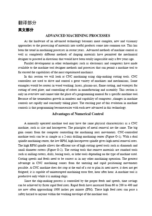
翻译部分英文部分ADV ANCED MACHINING PROCESSESAs the hardware of an advanced technology becomes more complex, new and visionary approaches to the processing of materials into useful products come into common use. This has been the trend in machining processes in recent years.. Advanced methods of machine control as well as completely different methods of shaping materials have permitted the mechanical designer to proceed in directions that would have been totally impossible only a few years ago.Parallel development in other technologies such as electronics and computers have made available to the machine tool designer methods and processes that can permit a machine tool to far exceed the capabilities of the most experienced machinist.In this section we will look at CNC machining using chip-making cutting tools. CNC controllers are used to drive and control a great variety of machines and mechanisms, Some examples would be routers in wood working; lasers, plasma-arc, flame cutting, and waterjets for cutting of steel plate; and controlling of robots in manufacturing and assembly. This section is only an overview and cannot take the place of a programming manual for a specific machine tool. Because of the tremendous growth in numbers and capability of comp uters ,changes in machine controls are rapidly and constantly taking place. The exciting part of this evolution in machine controls is that programming becomeseasier with each new advanced in this technology.Advantages of Numerical ControlA manually operated machine tool may have the same physical characteristics as a CNC machine, such as size and horsepower. The principles of metal removal are the same. The big gain comes from the computer controlling the machining axes movements. CNC-controlled machine tools can be as simple as a 2-axis drilling machining center (Figure O-1). With a dual spindle machining center, the low RPM, high horsepower spindle gives high metal removal rates. The high RPM spindle allows the efficient use of high cutting speed tools such as diamonds and small diameter cutters (Figure O-2). The cutting tools that remove materials are standard tools such as milling cutters, drills, boring tools, or lathe tools depending on the type of machine used. Cutting speeds and feeds need to be correct as in any other machining operation. The greatest advantage in CNC machining comes from the unerring and rapid positioning movements possible. A CNC machine does dot stop at the end of a cut to plan its next move; it does not get fatigued; it is capable of uninterrupted machining error free, hour after hour. A machine tool is productive only while it is making chips.Since the chip-making process is controlled by the proper feeds and speeds, time savings can be achieved by faster rapid feed rates. Rapid feeds have increased from 60 to 200 to 400 and are now often approaching 1000 inches per minute (IPM). These high feed rates can pose a safety hazard to anyone within the working envelope of the machine tool.Complex contoured shapes were extremely difficult to product prior to CNC machining .CNC has made the machining of these shapes economically feasible. Design changes on a part are relatively easy to make by changing the program that directs the machine tool.A CNC machine produces parts with high dimensional accuracy and close tolerances without taking extra time or special precautions, CNC machines generally need less complex work-holding fixtures, which saves time by getting the parts machined sooner. Once a program is ready and production parts, each part will take exactly the same amount of time as the previous one. This repeatability allows for a very precise control of production costs. Another advantage of CNC machining is the elimination of large inventories; parts can be machined as needs .In conventional production often a great number of parts must be made at the same time to be cost effective. With CNC even one piece can be machined economically .In many instances, a CNC machine can perform in one setup the same operations that would require several conventional machines.With modern CNC machine tools a trained machinist can program and product even a single part economically .CNC machine tools are used in small and large machining facilities and range in size from tabletop models to huge machining centers. In a facility with many CNC tools, programming is usually done by CNC programmers away from the CNC tools. The machine control unit (MCU) on the machine is then used mostly for small program changes or corrections. Manufacturing with CNC tools usually requires three categories of persons. The first is the programmer, who is responsible for developing machine-ready code. The next person involved is the setup person, who loads the raw stork into the MCU, checks that the co rrect tools are loaded, and makes the first part. The third person is the machine and unloads the finished parts. In a small company, one person is expected to perform all three of these tasks.CNC controls are generally divided into two basic categories. One uses a ward address format with coded inputs such as G and M codes. The other users a conversational input; conversational input is also called user-friendly or prompted input. Later in this section examples of each of these programming formats in machining applications will be describes.CAM and CNCCAM systems have changed the job of the CNC programmer from one manually producing CNC code to one maximizing the output of CNC machines. Since CNC machine tools are made by a great number of manufacturers, many different CNC control units are in use. Control units from different manufacturers use a variety of program formats and codes. Many CNC code words are identical for different controllers, but a great number vary from one to another.To produce an identical part on CNC machine tools with different controllers such as one by FANCU, OKUMA or DYNAPATH, would require completely different CNC codes. Each manufacturer is constantly improving and updating its CNC controllers. These improvements often include additional code words plus changes in how the existing code works.A CAM systems allows the CNC programmer to concentrate on the creation of an efficient machining process, rather then relearning changed code formats. A CNC programmer looks atthe print of a part and then plans the sequence of machining operations necessary to make it (Figure O-3). This plan includes everything, from the selection of possible CNC machine tools, to which tooling to use, to how the part is held while machining takes place. The CNC programmer has to have a thorough understanding of all the capacities and limitations of the CNC machine tools that a program is to be made for. Machine specifications such as horsepower, maximum spindle speeds, workpiece weight and size limitations, and tool changer capacity are just some of the considerations that affect programming.Another area of major importance to the programmer is the knowledge of machining processes. An example would be the selection of the surface finish requirement specified in the part print. The sequence of machining processes is critical to obtain acceptable results. Cutting tool limitations have to be considered and this requires knowledge of cutting tool materials, tool types, and application recommendations.A good programmer will spend a considerable amount of time in researching the rapidly growing volume of new and improved tools and tool materials. Often the tool that was on the cutting edge of technology just two years ago is now obsolete. Information on new tools can come from catalogs or tool manufacturers' tooling engineers. Help in tool selection or optimum tool working conditions can also be obtained from tool manufacturer software. Examples would be Kennametal's "TOOLPRO", software designed to help select the best tool grade, speed, and feed rates for different work materials in turning application. Another very important feature of "TOOLPRO" is the display of the horsepower requirement for each machining selection. This allow the programmer to select a combination of cutting speed, feed rate, and depth of cut that equals the machine's maximum horsepower for roughing cuts. For a finishing cut, the smallest diameter of the part being machined is selected and then the cutting speed varied until the RPM is equal to the maximum RPM of the machine. This helps in maximizing machining efficiency. Knowing the horsepower requirement for a cut is critical if more than one tool is cutting at the same time.Software for a machining center application would be Ingersoll Tool Company's "Actual Chip Thickness", a program used to calculate the chip thickness in relation to feed-per-tooth for a milling cutter, especially during a shallow finishing cut. Ingersoll's "Rigidity Analysis" software ealculates tool deflection for end mills as a function of tool stiffness and tool force.To this point we looked at some general qualifications that a programmer should possess. Now we examine how a CAM system works. Point Control Company's SmartCam system uses the following approach. First, the programmer makes a mental model of the part to be machined. This includes the kind of machining to be performed-turning or milling. Then the part print is studied to develop a machining sequence, roughing and finishing cuts, drilling, tapping, and boring operations. What work-holding device is to be used, a vise or fixture or clamps? After these considerations, computer input can be started. First comes the creation of a JOBPLAN. This JOBPLAN consists of entries such as inch or metric units, machine type, part ID, type of workpiece material, setup notes, and a description of the required tools.This line of information describes the tool by number, type, and size and includes theappropriate cutting speed and feed rate. After all the selected tools are entered, the file is saved.The second programming step is the making of the part. This represents a graphic modeling of the projected machining operation. After selecting a tool from the prepared JOBPLAN, parameters for the cutting operation are entered. For a drill, once the coordinate location of the hole and the depth are given, a circle appears on that spot. If the location is incorrect, the UNDO command erases this entry and allows you to give new values for this operation. When an end mill is being used, cutting movements (toolpath) are usually defined as lines and arcs. As a line is programmed, the toolpath is graphically displayed and errors can be corrected instantly.At any time during programming, the command SHOWPATH will show the actual toolpath for each of the programmed tools. The tools will be displayed in the sequence in which they will be used during actual machining. If the sequence of a tool movement needs to be changed, a few keystrokes will to that.Sometimes in CAM the programming sequence is different from the actual machining order. An example would be the machining of a pocket in a part. With CAM, the finished pocket outline is programmed first, then this outline is used to define the ro ughing cuts to machine the pocket. The roughing cuts are computer generated from inputs such as depth and width of cut and how much material to leave for the finish cut. Different roughing patterns can be tried out to allow the programmer to select the most efllcient one for the actual machining cuts. Since each tool is represented by a different color, it is easy to observe the toolpath made by each one.A CAM system lets the programmer view the graphics model from varying angles, such as a top, front, side, or isometric view. A toolpath that looks correct from a top view, may show from a front view that the depth of the cutting tool is incorrect. Changes can easily be made and seen immediately.When the toolpath and the sequence of operations are satisfactory, machine ready code has to be made. This is as easy as specifying the CNC machine that is to be used to machine the part. The code generator for that specific CNC machin e during processing accesses four different files. The JOBPLAN file for the tool information and the GRAPHICE file for the toolpath and cutting sequence. It also uses the MACHINE DEFINE file which defines the CNC code words for that specific machine. This file also supplies data for maximum feed rates, RPM, toolchange times, and so on. The fourth file taking part in the code generating process is the TEMPLATE file. This file acts like a ruler that produces the CNC code with all of its parts in the right place and sequence. When the code generation is complete, a projected machining time is displayed. This time is calculated from values such as feed rates and distances traveled, noncutting movements at maximum feed rates between points, tool change times, and so on. The projected machining time can be revised by changing tooling to allow for higher metal removal rates or creating a more efficient toolpath. This display of total time required can also be used to estimate production costs. If more then one CNC machine tool is available to machine this part, making code and comparing the machining time may show that one machine is more efficient than the others.CAD/CAMAnother method of creating toolpath is with the use of a Computer-aided Drafting (CAD) file. Most machine drawings are created using computers with the description and part geometry stored in the computer database. SmartCAM, though its CAM CONNECTION, will read a CAD file and transfer its geometry represents the part profile, holes, and so on. The programmer still needs to prepare a JOBPLAN with all the necessary tools, but instead of programming a profile line by line, now only a tool has to be assigned to an existing profile. Again, using the SHOWPA TH function will display the toolpath for each tool and their sequence. Constant research and developments in CAD/CAM interaction will change how they work with each other. Some CAD and CAM programs, if loaded on the same computer, make it possible to switch between the two with a few keystrokes, designing and programming at the same time.The work area around the machine needs to be kept clean and clear of obstructions to prevent slipping or tripping. Machine surfaces should not be used as worktables. Use proper lifting methods to handle heavy workpieces, fixtures, or heavy cutting tools. Make measurements only when the spindle has come to a complete standstill. Chips should never be handled with bare hands.Before starting the machine make sure that the work-holding device and the workpiece are securely fastened. When changing cutting tools, protect the workpiece being machined from damage, and protect your hands from sharp cutting edges. Use only sharp cutting tools. Check that cutting tools are installed correctly and securely.Do not operate any machine controls unless you understand their function and what the y will do.The Early Development Of Numerically Controlled Machine ToolsThe highly sophisticated CNC machine tools of today, in the vast and diverse range found throughout the field of manufacturing processing, started from very humble beginnings in a number of the major industrialized countries. Some of the earliest research and development work in this field was completed in USA and a mention will be made of the UK's contribution to this numerical control development.A major problem occurred just after the Second World War, in that progress in all areas of military and commercial development had been so rapid that the levels of automation and accuracy required by the modern industrialized world could not be attained from the lab our intensive machines in use at that time. The question was how to overcome the disadvantages of conventional plant and current manning levels. It is generally ackonwledged that the earliest work into numerical control was the study commissioned in 1947 by the US governme nt. The study's conclusion was that the metal cutting industry throughout the entire country could not copy with the demands of the American Air Force, let alone the rest of industry! As a direct result of the survey, the US Air Force contracted the Persons Corporation to see if they could develop a flexible, dynamic, manufacturing system which would maximize productivity. TheMassachusetts Institute of Technology (MIT) was sub-contracted into this research and development by the Parsons Corporation, during the period 1949-1951,and jointly they developed the first control system which could be adapted to a wide range of machine tools. The Cincinnati Machine Tool Company converted one of their standard 28 inch "Hydro-Tel" milling machines or a three-axis automatic milling made use of a servo-mechanism for the drive system on the axes. This machine made use of a servomechanism for the drive system on the axes, which controlled the table positioning, cross-slide and spindle head. The machine cab be classified as the first truly three axis continuous path machine tool and it was able to generate a required shape, or curve, by simultaneous slide way motions, if necessary.At about the same times as these American advances in machine tool control were taking Place, Alfred Herbert Limited in the United Kingdom had their first Mutinous path control system which became available in 1956.Over the next few years in both the USA and Europe, further development work occurred. These early numerical control developments were principally for the aerospace industry, where it was necessary to cut complex geometric shapes such as airframe components and turbine blades. In parallel with this development of sophisticated control systems for aerospace requirements, a point-to-point controller was developed for more general machining applications. These less sophisticated point-to-point machines were considerably cheaper than their more complex continuous path cousins and were used when only positional accuracy was necessary. As an example of point-to-point motion on a machine tool for drilling operations, the typical movement might be fast traverse of the work piece under the drill's position-after drilling the hole, anther rapid move takes place to the next hole's position-after retraction of the drill. Of course, the rapid motion of the slideways could be achieved by each axis in a sequential and independent manner, or simultaneously. If a separate control was utilisec for each axis, the former method of table travel was less esse ntial to avoid any backlash in the system to obtain the required degree of positional accuracy and so it was necessary that the approach direction to the next point was always the same.The earliest examples of these cheaper point-to-point machines usually did not use recalculating ball screws; this meant that the motions would be sluggish, and sliderways would inevitably suffer from backlash, but more will be said about this topic later in the chapter.The early NC machines were, in the main, based upon a modified milling machine with this concept of control being utilized on turning, punching, grinding and a whole host of other machine tools later. Towards the end of the 1950s,hydrostatic slideways were often incorporated for machine tools of highly precision, which to sonic extent overcame the section problem associated with conventional slideway response, whiles averaging-out slideway inaccuracy brought about a much increased preasion in the machine tool and improved their control characteristics allows "concept of the machining center" was the product of this early work, as it allowed the machine to manufacture a range of components using a wide variety of machining processes at a single set-up, without transfer of workpieces to other variety machine tools. A machining center differed conceptually in its design from that of a milling machine, In that thecutting tools could be changed automatically by the transfer machanism, or selector, from the magazine to spindle, or vice versa.In this ductively and the automatic tool changing feature enabled the machining center to productively and efficiently machine a range of components, by replacing old tools for new, or reselecting the next cutter whilst the current machining process is in cycle.In the mid 1960s,a UK company, Molins, introduced their unique "System 24" which was meant represent the ability of a system to machine for 24 hours per day. It could be thought of as a "machining complex" which allowed a series of NC single purpose machine tools to be linked by a computerized conveyor system. This conveyor allowed the work pieces to be palletized and then directed to as machine tool as necessary. This was an early, but admirable, attempt at a form of Flexible manufacturing System concept, but was unfortunately doomed to failure. Its principal weakness was that only a small proportion of component varieties could be machine at any instant and that even fewer work pieces required the same operations to be performed on them. These factors meant that the utilization level was low, coupled to the fact that the machine tools were expensive and allowed frequent production bottlenecks of work-in-progress to arise, which further slowed down the whole operation.The early to mid-1970s was a time of revolutionary in the area of machine tool controller development, when the term computerized numerical control (CNC) became a reality. This new breed of controllers gave a company the ability to change work piece geometries, together with programs, easily with the minimum of development and lead time, allowing it to be economically viable to machine small batches, or even one-off successfully. The dream of allowing a computerized numerical controller the flexibility and ease of program editing in a production environment became a reality when two ralated factors occurred.These were:the development of integrated circuits, which reduces electronics circuit size, giving better maintenance and allowing more standardization of desing; that general purpose computers were reduced in size coupled to the fact that their cost of production had fallen considerably.The multipie benefits of cheaper electorics with greater reliability have result in the CNC fitted to the machine tools today, with the power and sophistication progtessing considerably in the last few years, allowing an almost artificial intelligence(AI) to the latest systems. Over the years, the machine tools builders have produced a large diversity in the range of applications of CNC and just some of those development will be reviewed in V olume Ⅲ。
- 1、下载文档前请自行甄别文档内容的完整性,平台不提供额外的编辑、内容补充、找答案等附加服务。
- 2、"仅部分预览"的文档,不可在线预览部分如存在完整性等问题,可反馈申请退款(可完整预览的文档不适用该条件!)。
- 3、如文档侵犯您的权益,请联系客服反馈,我们会尽快为您处理(人工客服工作时间:9:00-18:30)。
附录一外文原稿:Anhydrous Ammonia Pressure Vessels In The Pulp AndPaper IndustryThe purpose of this article is to ensure that pulp and paper operating companies, their engineering consultants, and inspection contractors are informed about stress corrosion cracking in anhydrous ammonia service. The information was written by a task group of the TAPPI Engineering Division Nondestructive Testing and Quality Control Subcommittee. Bacteria in some activated sludge effluent treatment systems require supplementary food. In some cases, this food is provided by ammonia and phosphoric acid which are stored on the mill site. Ammonia is commonly stored as anhydrous liquid ammonia in carbon steel vessels at ambient temperature and 16 bar (250 psig) pressure.These vessels can be subject to stress corrosion cracking (SCC).SCC could cause release of ammonia, which is a hazardous chemical. SCC of carbon steel vessels in anhydrous ammonia service is somewhat analogous to that experienced in continuous digesters. For example, the importances of stress relief during fabrication and of in-service inspection are common to both. This article concerns storage in horizontal pressure vessels at ambient temperature, as this type of vessel is used in pulp and paper applications. Large refrigerated storage tanks are used for atmospheric pressure storage in the chemical industry.History of Scc In Ammonia Storage VesselsThe history of SCC in carbon steel ammonia storage vessels was reviewed by Loginow (1) and is also briefly summarized in a N ACE Technical Committee Report entitled “Integrity of Equipment in Anhydrous Ammonia Storage and Handling” (2). In the 1950s, liquefied ammonia began to be injected directly into soil for fertilization. Failure of carbon steel storage vessels by SCC began to occur. These failures were unexpected since liquefied ammonia had been used for many years in the refrigeration, chemical, and metal heat treating industries without reported problems.Investigation confirmed SCC to be the cause of cracking. Three recommendations weremade in 1962 that still form the basis of modern codes:• Pressure vessels should be fully stress relieved.• Extreme care should be used to eliminate oxygen from ammonia systems.•Ammonia should contain at least 0.2% water to inhibit SCC.Loginow reported that adoption of these recommendations practically eliminated SCC in carbon steel vessels in the agriculture industry. However, in a recent Western Canadian survey SCC was found in 100 of 117 field storage vessels inspected by wet fluorescent magnetic particle testing (WFMT) (3).Despite the above measures SCC continued to occur in road transport tanks constructed from high strength steels, in refrigerated storage vessels and in vessels which had been weld repaired but not subsequently stress relieved. An additional recommendation to limit steel tensile or yield strength was embodied in the U.S. and British ammonia storage codes, respectively (4, 5).• ANSI K61.1—Nominal tensile no greater than70,000 psi (580 MPa)• U.K. Code—Minimum specified yield strength shall not exceed 350 MPa (51,000 psi).PRACTICAL CONSIDERATIONSThis article is concerned mainly with practical considerations important to pulp and paper mills already possessing anhydrous ammonia storage vessels or planning to fabricate such vessels. In view of the industry’s experience with SCC in continuous digesters the governing objectives should be to control fabrication and inspection to prevent, or at least minimize, in-service problems including over-reaction to relatively minor crack indications. Guidance is available in the published codes and detailed information is available from some ammonia suppliers.FabricationThe two main objectives in fabrication should be to provide the most crack resistant vessel possible at reasonable cost and to ensure that an adequate inspection baseline is available for interpretation of subsequent in-service inspections.ASME Section VIII Division 1 does not require stress relief for anhydrous ammonia storage pressure vessels unless the owner specifies a lethal service designation.The lethal service designation requires radiographic testing (RT) of all butt welded joints plus post weld heat treatment.ANSI K-61.1-1989, “American National Standard Safety Requirements for the Storage and Handling of Anhydrous Ammonia,” adds several requirements:• Fabrication to ASME Section VIII Division 1 Table UW 12 at a joint efficiency less than 80% is not allowed.• Inspection and testing under UG-90(c) (2) (multiple, duplicate pressure vessel fabrication) is not allowed.• Steel used for pressure containing parts shall have a nominal tensile strength no greater than 580MPa (70,000 psi).• The minimum design pressure for ambient temperature storage shall be 16 bar (250 psig).• Post weld heat treatme nt is mandatory and a furnace of sufficient size to accommodate the entire vessel is recommended. Welded attachments may be made to pads after post weld heat treatment.• Horizontal vessels shall be mounted on saddles which extend over at least one third of the shell’s circumference. Thermal expansion and contraction shall be allowed for and means provided to prevent corrosion between the shell and the saddles.The 1986 British Code “Storage of Anhydrous Ammonia under Pressure in the United Kingdom” require s:• Steel must have specified minimum yield strength less than 350 MPa (51,000 psi).• Weld filler must have minimal strength overmatch compared with the base plate.• 100% magnetic particle inspection of all internal welds in order to provide a record against which all future inspections of the vessel can be assessed.• No welding is permitted after stress relief without subsequent local stress relief.• Concrete saddles are prohibited.• Support must be on continuously welded steel saddles attached befor e stress relief.Although the British Code does not state that magneti particle inspection should be by WFMT it is generally agreed that WFMT is the most sensitive technique and should be used for inspection of ammonia storage vessels. All inspection should be performed by qualified technicians. SNT-TC-1A Level II is a recommended minimum.One pulp and paper company has added the following requirements for fabrication of such vessels:• Incorporation of a “corrosion allowance” of at least1.6 mm (1/16 in.) to permit minor defect chasing during in-service inspections and to provide a margin against pitting which may occur if water is allowed to enter an out of service vessel.• All weld toes profiled by grinding prior to wet fluorescent magnetic particle test ing (WFMT). All WFMT indications greater than 1.6 mm (1/16 in.)to be removed by grinding before post weld heat treatment.• Shear wave ultrasonic testing (UT) of nozzle-to-shell welds permitted if RT is judged impractical.• WFMT to be repeated after fina l hydrotest test of the vessel and the report retained by the owner.• Vessel to be dried completely after hydrotest test and nitrogen padded until filled with ammonia.Valves, piping, and fittingsBoth the ANSI and U.K. codes address piping, valves, and fittings. A detailed summary is beyond the scope of this article, but some points are worth noting.• ANSI K61.1 requires all nonrefrigerated ammonia piping to meet the requirements of ANSI/ASME B31.3 “Chemical Plant and Petroleum Refinery Piping.”• The U.K. Code states copper and copper bearing alloys shall not be used.ANSI/ASME B31.3 requires a minimum of 5% of piping welds be radiographically tested. Valves and other apparatus should be rated for ammonia service and should not contain copper or copper alloy components.In one case, a nickel rupture disc corroded to failure at its periphery due to formation of an ammonia solution at a gasketed joint exposed to the weather.In-service inspectionVessel entry Liquid or gaseous ammonia is hazardous and in some jurisdictions release of ammonia vapor to the atmosphere is prohibited by law. Vessels must be properly purged by water and/or steam. Detailed procedures for vessel purging and entry are available from ammonia suppliers (6).Inspection procedures The ANSI standard does not address in-service inspection but does state weld repair or alteration must conform to the current edition of the National Board Inspection Code (NBIC).The 1992 edition of the NBIC includes nonmandatory guidelines for inspection of liquid ammonia vessels (7).These guidelines recommend:• Power buffing or light sandblasting as surface preparation for inspection• All interior welds be examined by WFMT.• Cracks should be removed by grinding without encroaching on the minimum thickness required by ASME Section VIII and the original design.• Weld repairs, regardless of size, should be post weld heat treated wherever possible.Light grinding does increase the sensitivity of WFMT compared to sandblasting or power buffing (8).For example the NBIC mandates grinding as surface preparation for deaerator inspection. The omission of grinding in the guidelines for ammonia vessel in-service inspection may be due to concern that rough grinding may produce residual stress sufficient to initiate SCC in anhydrous ammonia service. If welds have been properly profiled for WFMT on initial fabrication, then grinding for in-service inspection should not be needed.The NBIC guidelines also state that other inspection methods such as acoustic emission or ultrasonics may be used and that fracture mechanics may be used to assess the integrity of vessels where complete removal of cracks is not practical.Normally the only corrosion that occurs in anhydrous ammonia vessels is due to water ingress during out of service periods. Shallow pitting, however, has been found in the bottom of some vessels beneath oily deposits. The source of oil is presumed to be from compressors used to handle the ammonia.In view of concerns over air contamination due to vessel entry and residual stress imparted by grinding nonintrusive inspection, techniques like acoustic emission and UT could be considered by vessel owners. The British Code does not mention nonintrusive inspection of ambient temperature pressure vessels but does state that, if acoustic emission is to be used for spherical storage vessels, a reference base should be taken during initial hydrotesting. Nonintrusive inspection is being used in other industries (9).Vessel refilling Safety procedures should be established for refilling a vessel that has been emptied for inspection. It is also very important to purge the vessel of air to prevent the occurrence of SCC. Detailed instructions are available from ammonia suppliers (10). If a vessel is not to be returned to service immediately after inspection, then care should be taken to dry it and possibly nitrogen-pad it depending on the time it will remain out of service. Inspection frequency Neither the ANSI document nor the NBIC deals with inspection frequency. The British Code recommends the following:• WFMT inspection of 100% of all internal butt welds within the first three years of service• WFMT re-inspection within 2 years if significant defects are found• Subsequent to no significant defects being found,any subsequent inspection should include WFMT of all Tee junctions and 10% of the total length of butt welds• In no case should the subsequent examination interval exceed 6 years.It is apparent from the above that latitude can exist for in-service inspection techniques andfrequencies. Each owner should determine inspection frequency in conjunction with the appropriate authority. Some jurisdictions require a 3-year inspection frequency.SUMMARYThe use of carbon steel pressure vessels for storage of anhydrous ammonia in the pulp and paper industry could be a non-event or deteriorate into a cycle of inspection and repair. This article has highlighted major concerns related to SCC. There is a wealth of additional information available on all considerations related to these vessels from the ANSI and British Codes, the NACE document, ammonia suppliers, and the current technical literature. The American Institute of Chemical Engineers(AIChE) holds the annual AIChE Ammonia Safety Symposium aimed at finding ways to safely manufacture, transport, and store ammonia and related chemicals. The proceedings of these symposia are published by AIChE. It is recommended that any owner of such vessels keep aware of current expertise.Reid is materials and corrosion section head with MacMillan Bloedel Research, 4225 Kincaid St., Burnaby, BC, Canada V5G 4P5.Task group members: Craig Reid; R.S. Charlton, Levelton Associates Consulting Engrs.; R.C. Faloon, MQSInspections Inc.; and W. E. Boudreau, Belle Testing Inc.Literature cited1.Loginow,A.W. , Materials Performance 25 (12): 18(1986).2.NACE Technical Committee report 5A192, Integrity of Equipment in Anhydrous Ammonia Storage and Handling, Houston, NACE Storage Tank, Spokane, 1992.3.Stephens, J. D. and Vidalin, F., 1994 AIChE Ammonia Symposium Notes,American Institute of Chemical Engineers, New York, p. 9.pressed Gas Association Inc., American National Standard Safety Requirements for the Storage and Handling of Anhydrous Ammonia ANSI K61.1-1989, Arlington, V A, 1989 (CGA Pamphlet G-2.1-1989).5.Storage of Anhydrous Ammonia Under Pressure in the United Kingdom, London, Her Majesty’s Stationery Office, 1986. (Health and Safety Booklet HS/G 30)inco Fertilizers (U.S.) Inc., Decommissioning an Ammonia Storage Tank, Spokane, 1992.7. The National Board of Boiler and Pressure Vessel Inspectors,National Board Inspection Code: A Manual for Boiler and Pressure Vessel Inspectors, Columbus, OH, 1992, p.197.8.Reid, J. C. and Reid, C., TAPPI 1992 Engineering Conference Proceedings, TAPPI PRESS, Atlanta, Book I, p.163.9.Conley, M. J., Sture, A., and Williams, D., “Ammonia Vessel Integrity Program: A Modern Approach, 1990 AIChE Ammonia Symposium Notes, New York, AIChE, 1990.inco Fertilizer s (U.S.) Inc., “Commissioning an Ammonia Storage Tank”, Spokane, 1992.附录二外文翻译:纸浆和造纸行业中的无水氨压力容器本文的目的是为了确保纸浆和纸张经营公司,他们的工程顾问,承建商了解在脱水氨设备中的应力腐蚀开裂现象。