三丰-密测多友-Mitutoyo投影仪PH-3500操作作业指导书
数字式影像测量仪操作指导书
一、影像的使用
1)打开总电源,打开电脑。
2)仪器总电源打开后,把仪器的投影的灯光打开。
3)打开电脑桌面上的影像软件Gager3d 5.0.exe,进入影像检测准备。
4)视工件大小选择1-7倍的放大系数,将工件放在工作台上,位于影像光之内,调好焦距。
此时屏慕上出现的工件表面的影像必须清晰可见、无阴影。
5)摆正工件,在摆正过程中应对被测物釆取轻微敲击,直至选取被测物体的一边与X轴或Y 轴重合。
操作时可以来回运动几次,可以提高测量的精确度。
6)可前后左右移动工作台,直到要检测的部位清楚在可视范围内
7)然后,可根据所需要检测的方式,在系统软件上找相对应的工具进行检测。
二、利用影像常见的几种测量
1)长度、宽度测量
2)圆的内、外径及圆的半径测量
3)角度的测量
4)中心距测量
5)圆弧测量
6)样品轮廓测量
7)。
各类仪器校正指导书和检定作业指引

5.6 设定检查点:
5.6.1 根据内径千分尺的范围分别设定如下:
测定范围 检 查 点
共计
0-0.80mm 0.05; 0.10; 0.20; 0.50; 0.80
5 点;
0-1.00mm 0.05; 0.10; 0.20; 0.50; 0.80;1.00 6 点。
5.7 检定:
5.7.1 确认测量用工作面和测量头无生锈及损伤等。
ISO 审查:
审:
日期:
发行部门
品管部
文件编号
文件名称
塞规检定作业指导书
生效日期 年 月 日
版次 A/0 页次 1/1
1.0 目的:确保公司所使用塞规符合工艺要求,保证塞规的精度, 使塞规的误差在规定范围内。
2.0 范围:所有塞规的检定作业。 3.0 职责和权限:
3.1 本作业指导书管理责任部门为品管部仪校单位,执行责任部门为品管部仪校单位、塞规 使用部门。
5.7.2 确认杠杆百分表之运作顺畅(正反方向确认)。
5.7.3 依据所设定检查点正反方向确认杠杆式百分表的测定间距:
测定间距 0.05mm 0.10mm 0.20mm 0.50mm 0.80mm 1.00mm;
以 mm 为 +0.02 +0.04 +0.06 +0.08
单位。
5.8 容许偏差:容许偏差值 ±0.01mm ±0.01mm -0.01mm -0.01mm -0.01mm
-0.01mm。
5.9 检定结果判定: 根据百分表之容许偏差作出 OK 或 NG 的判定。
5.10 检定周期:每六个月一次。
5.11 检定结果记录: 将检定结果记录在《仪器检验报告》上。
6.0 使用表单:
6.1《仪器检验报告》————————————————
Mitutoyo Corporation 20-1, Sakado 1 三次元测量仪使用说明书

⑤ 连接区域⑥ 显示装置(LCD)⑦ 输出连接器⑫ 调节螺钉⑬ 电池盖■ 显示装置(LCD)⑭ [HOLD]键⑮ [ZERO/ABS]键⑯ [PRESET]键⑰ [in/mm]键(仅限in/mm产品)⑱ 符号显示⑲ 功能锁定显示⑳ 保持显示㉑ 低电压显示㉒ INC显示㉓ 预设显示㉔ 单位显示按键操作图标目录1. 部件名称 (1)2. 安装电池 ..............................................................第1页3. 使用注意事项 ..........................................................第2页4. 基准点设置 ............................................................第2页5. 测量方法 ..............................................................第2页6. 按键功能 ..............................................................第2页7. 功能锁定功能(防止意外操作) ............................................第2页8. 错误和故障排除 ........................................................第3页9. 测量头和接长杆的安装/拆卸方法 ........................................第3页10. 规格 ..................................................................第3页11. 输出功能 ..............................................................第3页12. 选件 ..................................................................第3页13. 非现场维修(收费) (3)■ 测力• 使用棘轮锁定装置确保测力一致。
XT-LP3500用户说明书
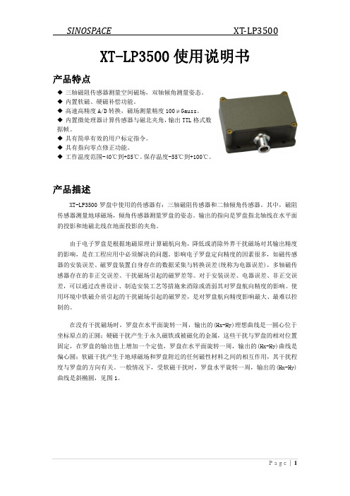
XT-LP3500使用说明书产品特点◆三轴磁阻传感器测量空间磁场,双轴倾角测量姿态。
◆内置软磁、硬磁补偿功能。
◆高速高精度A/D转换,磁场测量精度100μGauss。
◆内置微处理器计算传感器与磁北夹角,输出TTL格式数据帧。
◆具有简单有效的用户标定指令。
◆具有指向零点修正功能。
◆工作温度范围-40℃到+85℃。
保存温度-55℃到+100℃。
产品描述XT-LP3500罗盘中使用的传感器有:三轴磁阻传感器和二轴倾角传感器。
其中,磁阻传感器测量地球磁场,倾角传感器测量罗盘的姿态。
输出的指向是罗盘指北轴线在水平面的投影和地磁北线在地面投影的夹角。
由于电子罗盘是根据地磁原理计算磁航向角,降低或消除外界干扰磁场对其输出精度的影响,是在工程应用中必须解决的问题。
影响电子罗盘定向精度的因素很多,如磁传感器的安装误差、磁罗盘装置自身存在的数据采集与转换误差(统称为电器误差),多轴磁传感器存在的非正交误差、干扰磁场引起的磁罗差等。
对于安装误差、电器误差、非正交误差,可以通过改善设计、制造安装工艺等措施来消除或消弱其对罗盘航向精度的影响。
使用环境中铁磁介质引起的干扰磁场引起的磁罗差,是对罗盘航向精度影响最大、最难以控制的。
在没有干扰磁场时,罗盘在水平面旋转一周,输出的(Hx-Hy)理想曲线是一圆心位于坐标原点的正圆;硬磁干扰产生于永久磁铁或被磁化的金属,这些干扰与罗盘的相对位置固定,在罗盘的输出值上增加一个定值,罗盘在水平面旋转一周,输出的(Hx-Hy)曲线是偏心圆;软磁干扰产生于地球磁场和罗盘附近的任何磁性材料之间的相互作用,其干扰程度与罗盘的方向有关。
一般情况下,受软磁干扰时,罗盘水平旋转一周,输出的(Hx-Hy)曲线是斜椭圆,见图1。
-2-1.5-1-0.500.51 1.52-2-1.5-1-0.500.511.52Hx/Hx-maxH y /H y -m a x图1罗盘是检测磁场的传感器,对于外界干扰磁场和地球磁场,罗盘无法做到实时、完全的区分,在使用中为罗盘提供干扰磁场小的位置是保证罗盘精度的关键,同时,在使用中减少罗盘的线加速度和转动加速度是保证罗盘精度的另外一个关键。
公司实验室三次元影像测量仪作业指导书
1.0目的:
为规范三次元的操作,确保测量数据的准确度。
2.0范围:
适用于本公司三次元的操作。
3.0职责:
由相关三次元的操作使用人员执行。
4.0内容
4.1使用环境:
4.1.1检定温度:20±1℃,温度变化:<0.5/h℃,仪器平衡温度时间:48H。
4.1.2室内相对湿度应控制在55﹪-65﹪之间。
4.1.3因测量机对静电和灰尘的影响特别敏感,故地面和墙面的设计应充分考虑防尘,抗静电。
并在
清洁时不得扬起灰尘。
4.2仪器特性:
4.2.1量程:X=400mm,Y=500mm,Z=300mm。
4.2.2分辨率为:0.5um。
4.2.3测量不确定度:单轴:(2.3+L/300)um
空间:(2.8+L/250)um。
4.3基本操作:
4.3.1开机。
打开主机电源.
4.3.2在计算机的Windows桌面上用鼠标双击“AC-CMIS”快捷按钮,即可进入AC-DMIS基本软件的操
作界面。
4.3.3被测产品用治具固定好,摆正产品。
4.3.4点击菜单栏的坐标系进行初始化。
4.3.5点击工具栏的测针按钮,选取适当的测针。
4.3.6按照测量图纸的要求进行采点,作出所需的元素。
4.3.7根据需要,利用工具栏的公差按钮,由多个元素求出所需的形状公差或位置公差。
4.3.8保存并记录所需的数据.
分发部门:□总经理□管代□行政□资材□工程□工模□装配■品质部□喷印□市场□塑胶。
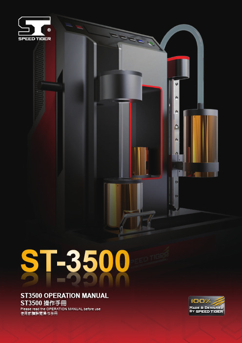
ST-3500 操作手冊说明书
Made & Designed ByST-3500ST-3500ST3500 OPERATION MANUAL ST3500操作手冊Please read the OPERATION MANUAL before use 使用前請詳閱操作手冊ST3500ST3500 OPERATION MANUALT3500操作手冊Heating Sleeve 導熱套筒T oolholder Extension Base刀桿延長桿基座↓Round Tray刀桿隔環↓Index索 引▓Introduction產品介紹▓Standard Mode Operation標準模式操作說明Insert the tool燒結刀具Take out the tool取出刀具操作▓Custom Mode Operation自選模式操作說明▓Heating Sleeve Instruction導熱套筒使用說明▓Shrink Fit Program for Dual End Set雙頭龍燒結操作說明T wo M odes I ntroduction模式介紹Standard Mode 標準模式Heating time have been set up according to the size of shank. This setting is based on YAMAKEN's actual test results. If you would like to adjust heating seconds, please choose Custom Mode Operation.燒結時間已根據刀桿內孔徑不同設定完成。
燒結時間設定是依據山謙Move the induction coil to the properposition. (The distance from the top ofinduction coil to the top of chuck is about25 ~ 30mm)手持握把將加熱線圈移動至適合的位置(加熱頭端部至燒結刀桿鼻端距離約25~30mm)。
投影仪作业指导书

文件编号版 本V1.0页 数 共5页4.1仪器校验4.3基本操作1、 目的规范投影仪测量操作,提供准确测量数据。
2、 适用范围适用测试中心投影仪操作。
首先选择测量时所用的放大倍数,把光学玻璃放在工作台上,调节焦距使光学玻璃的网格在软件上显示最清晰,然后用点击菜单栏中的“工具”,在出现的下拉菜单中选择“取绘图面比例尺”命令,然后在光学玻璃的网格上用鼠标左键点击两点取一定长度的线段(必须知道这条线段的实际长度,一般是取光学玻璃上若干个网格十字中心点的距离),两点取完后会弹出一个对话框输入刚才两点取的线段的实际长度,点击"确定"后在软件的命令行里会显示当前比例尺的值,完成取绘图面比例尺。
画圆:选择画圆命令,在主画面上点击鼠标左键输入第一点,移动鼠标点击鼠标左键输入第二点,再移动鼠标点击鼠标左键输入第三点,完成画圆;3、 职责由测试员执行操作,并做好日常保养。
4、 工作程序产品测试前,使用标准件对仪器进行复位、对焦处理,并记录校验的数据;仪器复位过程中注意观察仪器空转情况是否正常。
4.2 取绘图面比例尺画线:选择画线命令,在主画面上点击鼠标左键输入第一点,再移动鼠标点击鼠标左键输入第二点,即完成画线;选择存放比例位置文件编号版本V1.0页数共5页画弧:选择画弧命令,在主画面上点击鼠标左键输入第一点,移动鼠标点击鼠标左键输入第二点,再移动鼠标点击鼠标左键输入第三点,即完成画弧;画平行线:选择画平行线命令,左键点击主画面上的任意一条线段作为基准线,移动鼠标到另一边点击鼠标左键确定平行线起点,再移动鼠标点击鼠标左键确定垂直线上的第二点,即完成画平行线;画垂直线:选择画垂直线命令,左键点击主画面上的任意一条线段作为基准线,移动鼠标点击鼠标左键确定垂直线上的第一点,再移动鼠标点击鼠标左键确定垂直线上的第二点,即完成画垂直线;注:产品在测绘取点的时候,一定要边看界面右上角的局部放大示图,一边要点击上、下、左、右方向键,以确保取点位置正确。
Mitutoyo操作说明

原点 P1 P2
X
雅玛可精密塑胶(无锡)有限公司 YAMAKOH PRECISION (WUXI)CO.,LTD
坐标系设定
3· 三点原点设定 3
「输入按键」 按下
YAMAKOH
选择
「功能」
Y
P3 原点 P1 P2
操作步骤︰ 1﹒选择好命令键 , 2﹒在产品X轴上从原点开始按顺序取2到50 点左右(P1,P2) ﹐然后在Y轴上取1到50点 左右(P3) 3﹒P1到P2为X轴与P3的Y轴交点为原点.
6
12 14
13
15 7 9 17 8 2 1 3 4 16
雅玛可精密塑胶(无锡)有限公司 YAMAKOH PRECISION (WUXI)CO.,LTD
构造说明
YAMAKOH
(18)主显示屏 (19)功能键图示区 (20)人工智能测量键 (21)坐标输入形式选项 (22)坐标系设定选项 (23)基本量测指令键 (24)巨集指令量测键 (25)自定义选项 (26)状态显示区 (27)功能键(和功能键图示区对应) (28)取点键 (29)删除键 (30)视窗和计数器显示格式 (31)确定键 (32)计数器模式 (33)游标方向移动键 (34)数字键
Y’
Y P1 原点
X
雅玛可精密塑胶(无锡)有限公司 YAMAKOH PRECISION (WUXI)CO.,LTD
坐标系设定
3· 两点原点设定 2
「输入按键」 按下
YAMAKOH
选择
「功能」
Y
操作步骤︰ 1﹒选择好命令键 , 2﹒在产品上分别测取两点(P1 P2) 左图所示(两点 可以是几何形状的中心) 3 ﹒P1点为坐标系X,Y轴的原点,P1到P2为X轴
三坐标测量机操作规程

三坐标测量机操作规程三坐标测量机操作规程一、启动前的准备1.确保实验室温度在20±2℃,湿度在25%--75%RH;2.确保电路、气路连接正常,机器导轨无障碍物;3.用酒精擦拭导轨,由内向外依次擦拭(严禁用酒精擦洗光栅);4.检查电压、地线等是否正常,对前置过滤器、冷干机等进行放水检查,查看三坐标测量机上的三联过滤器是否干净;5.打开UPS,再依次打开气源开关(总气阀开关—冷干机开关—三坐标气源开关),保证气压在0.4MPa—0.6MPa(一般为0.48MPa),调节气压时,将压力表下的黑色旋钮拉下,左右旋转即可调节气压,调好气压后,将黑色旋钮按回原位。
二、测量机系统启动1.启动计算机,打开测头控制器开关(黑色);2.打开控制柜电源开关,系统进入自检状态(操纵盒指示全亮),若系统稳定,则控制柜里的数字为“7”不变,若系统不稳定,则控制柜里的数字在乱变,那就需要重新启动一次系统(重新关开控制柜电源开关即可,时间间隔需20秒以上);3.自检完后,点击PC-DMIS软件图标,启动软件系统;4.冷启动时,软件窗口会提示进行及其回零操作。
此时将操纵盒的“加电”键(SERYO PWR ON)按下,再按下“自动”键(AUTO),再在软件窗口中点击确定,机器将自动回到零位;5.待机器回到零位后(零位是系统默认的坐标原点),PC-DMIS进入正常工作界面。
三、测量机系统关闭1.关闭系统时,先将测头移到安全高度;2.退出PC-DMIS系统,关闭控制柜电源和测座控制器电源;3.反顺序关闭气源开关(三坐标气源开关—冷干机开关—总气阀开关),并对过滤器进行放水处理;4.关闭计算机、UPS等电源。
四、软件界面在软件窗口中点击“文件—打开/新建”(快捷键:打开CTRL+O,新建:CTRL+N),“新建”文件时需要在“新建零件程序”窗口中的“零件名”处输入名称(名称不能用中文)其余项不管;“打开”文件则只要找到所需文件的路径并双击,PC-DMIS进入正常工作界面。
三丰通用测量程序操作指南
4 基本测量..................................................................................................................................................4-1
数字式测量投影仪操作指导书
一、投影屏的使用1仪器总电源打开后,投影屏旋转角度值也在DC-3000上显示出来,可通过DC-3000内部设置进行度、分与百进制的转换。
2松开锁紧螺丝,用投影屏框上的小手柄把磨砂镜片压紧,并使屏框上的白色短线与零位标记对齐。
3)视工件大小选择10或20x的物镜,将工件放在工作台上,位于反射照光斑之内,调好焦。
此时屏慕上出现的工件表面的影像必须清晰可见、无阴影。
4)摆正工件,在摆正过程中应对被测物釆取轻微敲击,直至选取被测物体的一边与X轴或丫轴重合。
操作时可以来回运动几次,可以提高测量的精确度。
5)然后,以这条与X轴或丫轴重合的边为基准,把显示面板中的X, Y, Z这三坐标值设为0, 此时就可以根据实际测试的尺寸来测量,用手轮传动的过程中,动作要平缓,不要用力过大,直至测量出结果。
二、利用投影屏常见的几种测量1)轮廓测量(釆用标准放大图)a)根据被测件大小确定物镜倍率,再按零件图纸制作与物镜倍率相同比例的标准放大图,材料选用伸缩性较小的透明塑胶片。
在图上也可以画出允许的公差带。
b)将标准放大图用弹性压板压在投影屏上。
c)把工件放在工作台上,调好焦,移动X,丫工作台使零件影像与放大图套准。
d)若工件影像与放大图的偏差在公差带之内,则为合格;若超出范围则为不合格,偏差数值可用X,Y坐标测量出来。
2)坐标测量a)工件放在工作台上,选用倍率较高的物镜,调好焦。
b)投影屏旋转零位对准,即屏框上的短白线对准零位标记。
c)调整工件被测方向与测量轴平行。
如X轴。
d)移动工作台,将被测工件的另一个端面与丫轴重合,然后把显示面板的X ,Y,Z数值都设置为0,此时即可进行测量。
3)角度坐标测量a)工件放在工作台上,视零件大小选用物镜倍率,调好焦。
b) 将被测角顶点调整到投影屏刻线中心上。
c) 旋转投影屏,使任一条刻线对准被测角的一边,角度数显示值清0。
d) 再次旋转投影屏。
使该刻线对准被测角的另一边。
这时,角度数显示值即为被测角度值。
Lab-X3500中文操作手册
19
第四部分:光谱扫描
选择测量条件
21
光谱扫描输出
22
打印扫描
26
谱峰鉴定
26
改变量程
26
目标区域
26
叠加扫描
27
由RS232传输扫描
28
2
Lab-X3500中文操作手册
退出
29
第五部分:校准
建立新的校准程序
30
设定所有的测量条件和测定标准样品
31
测量条件
31
测量条件(总结)
33
编辑/增加其他测量条件
拆箱和安装 拆箱
小心地打开包装箱,取出Lab-X3500,检查是否有任何可能出现的损坏,再取出一个装 有附件和备品的小盒子和塑料包。
为了减少运输过程中损坏的危险,已从仪器中卸掉X射线警告灯泡和灯罩,在任何测量 开始之前,必须把它们装上,这些东西,在备件盒中可以找到。装灯泡时,保证它被紧紧地 装在灯泡座上,然后,用两个螺丝和提供的六角扳手固定黄色的灯泡。
如果指示的输入电压不正确,可作如下改动: 关闭开关并拔掉电源线。 用小螺丝刀撬开保险支架。 拉下黑色的电压指示器,同时取下一个小的20mm的正方形连接器板。 波动电压指示器(白色塑料),一直拨到所需要的电压为止,此时,电压值出现在板
9
Lab-X3500中文操作手册
面上。 把连接器板放回到原来位置。 重新安装保险支架并保证指示器被调到所需要的电压。
操作者的所有操作都是通过软件控制来完成的,通过内置式键盘来进行命令输入。软件 信息和结果显示在两行液晶显示屏上。分析结果、光谱扫描等可用装在仪器内部的点阵式打 印机打印出来。接通RS232系统,可以传输和接收数据。
根据其应用目的和所要求的应用配置包不同,Lab-X3500有各种各样的配置,它们的主 要区别是所用的激发源、探测装置和提供的应用软件包不同。
3500_53操作 手册
操作手册本特利内华达资产状态监测3500/53超速检测系统3500/53超速检测系统操作手册版权所有1997 本特利内华达保留所有权力本手册内容如有更改,恕不另行通知。
以下为通用电气公司在美国及其他国家的商标:Actionable Information, Actionable Information to the Right People at The Right Time, ADRE, Bently Nevada, CableLoc, Data Manager, Decision Support, DemoNet, Dynamic Data Manager, Dynamic Transmitor, Engineer Assist, FieldMonitor, FluidLoc, FlexiTIM, FlexiTAM, Helping you Protect and Manage All Your Machinery, HydroVU, Key Φ, Keyphasor, Machine Condition Manager 2000, MachineLibrary, MicroPROX, Move Data, Not People, Move Information, Not Data, Performance Manager, PROXPAC, Proximitor, REBAM, Seismoprobe, System 1, TDIXconnX, Tecknowledgy, TipLoc, TorXimitor, Transient Data Manager, Trendmaster, TrimLoc, VAM, Velomitor, Xlerometer联络信息当您无法与本特利内华达当地代表联系时,请通过下列途径:邮寄地址1631 Bently Parkway SouthMinden, Nevada USA 89423USA电话 1.775.782.36111.800.227.5514传真 1.775.215.2873因特网/bently补充信息注意注意::本手册未包含运行与维护该产本手册未包含运行与维护该产品所必需的所有信息品所必需的所有信息品所必需的所有信息。
网络视频监控测试仪3500操作说明书
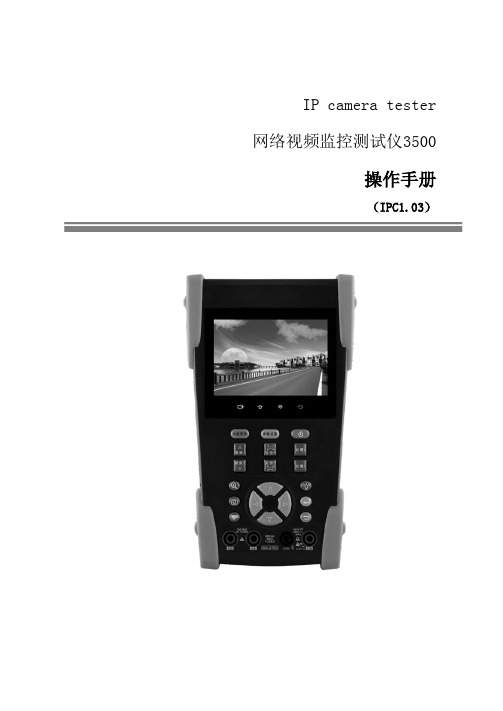
IP camera tester 网络视频监控测试仪3500操作手册(IPC1.03)⏹感谢您购买工程宝安防监控视频测试仪。
使用前请务必阅读使用说明书,并正确使用。
⏹为了能安全地使用本仪器,请您先仔细阅读使用说明书上的「安全注意事项」。
⏹说明书阅读后请妥善保管,以便随时查阅、参考。
⏹附有的保修凭证或机身的保修封贴,请勿损坏。
⏹使用中遇到问题,或仪器出现损坏时,请与公司技术部联系。
目录一、安全事项--------------------------------------------------------- 1二、IP网络视频监控测试仪简介 ------------------------------------------- 22.1 概述------------------------------------------------------- 22.2 产品特点---------------------------------------------------- 22.3 产品功能---------------------------------------------------- 42.4 产品配件--------------------------------------------------- 102.5 仪表各部位名称和功能: --------------------------------------- 11三、操作说明-------------------------------------------------------- 153.1 电池安装及充电说明------------------------------------------- 153.2 仪器连接--------------------------------------------------- 163.2.1 网络摄像机连接---------------------------------------- 163.2.2 模拟摄像机连接---------------------------------------- 173.3.3 SDI数字摄像机连接------------------------------------- 183.3 功能菜单操作------------------------------------------------ 193.3.1 视频监控--------------------------------------------- 213.3.1.1 云台控制器参数设置------------------------------ 223.3.1.2 色彩及存储设置--------------------------------- 243.3.1.3 视频图像放大----------------------------------- 253.3.1.4 拍照截图-------------------------------------- 263.3.1.5 录像功能-------------------------------------- 263.3.1.6 相片浏览-------------------------------------- 273.3.1.7 录像回放-------------------------------------- 283.3.1.8 视频信号测量*(*定制功能型号见附表)--------------- 293.3.2 图像发生器 TV OUT ------------------------------------ 313.3.3 ONVIF网络摄像机测试----------------------------------- 323.3.4 IP网络摄像机测试-------------------------------------- 393.3.5 SDI摄像机测试 *(*定制功能型号见附表)------------------- 423.3.6 IP地址扫描 ------------------------------------------ 433.3.7 PING连通性测试--------------------------------------- 443.3.8 网线测试器------------------------------------------- 453.3.9 寻线器*(*定制功能型号见附表) -------------------------- 453.3.10 端口闪烁-------------------------------------------- 473.3.11 串口工具-------------------------------------------- 483.3.12 激光功率计*(*定制功能型号见附表)---------------------- 493.3.13 可见红光源*(*定制功能型号见附表)---------------------- 503.3.14 高精度数字万用表*(*定制功能型号见附表)----------------- 523.3.15 视频播放器------------------------------------------ 593.3.16 音乐播放器------------------------------------------ 603.3.17 手电筒--------------------------------------------- 603.3.18 PoE/PSE电压测试功能--------------------------------- 613.3.19 TDR线缆故障测量*(*定制功能型号见附表)----------------- 613.3.20 计算器--------------------------------------------- 643.3.21 浏览器--------------------------------------------- 653.3.22 IPC viewer 移动客户端 ------------------------------ 663.3.23 DC12V电源输出--------------------------------------- 673.3.24 应用工具-------------------------------------------- 693.3.25 APPS工具夹----------------------------------------- 763.3.26 系统设置-------------------------------------------- 773.3.27 更新----------------------------------------------- 803.4 DC12V 1A供电输出-------------------------------------------- 803.5音频测试功能 ------------------------------------------------ 81四、技术参数-------------------------------------------------------- 824.1 技术参数总表------------------------------------------------ 824.2 万用表技术参数---------------------------------------------- 844.3 光功率计技术参数 -------------------------------------------- 864.4可见红光源技术参数-------------------------------------------- 87一、安全事项⏹使用本仪器时,请遵守当地的电气使用相关规则,避免于医院、加油站等不可使用电气的地方使用。
MITUTOYO 高精度 CERA 高度测量仪 系列515的产品说明说明书
Precision Measuring Equipment and Industrial Supplies since 1924.4841W.ChicagoAve.•Chicago,IL60651•Ph:773.261.2182•Fax:773.261.2867•***********************MITUTOYO - HEIGHT MASTERHEIGHT MASTERHigh Accuracy CERA Height Master - Series 515 V-2Height Master - Series 515 V-3Digimatic E-Type Height Master - Series 515 V-4E-Type Height Master - Series 515 V-5Height Master - Series 515 - Vertical, Horizontal V-6Riser Block - Series 515 V-6Clamping Block Set for Bore Gage V-7Check Masters - Ceramic and Steel Blocks V-8, V-9Caliper Checker - Series 515 V-10Depth Micro Checker V-10Cera Straight Master V-11515-310Application Examples with AccessoriesCalibratesDial Bore Gagesprobe movementsTwo-point contactDial Bore Gage withroller guide515-319Staggered blocksmake it possibleto transfer top andbottom land heights 1" BLOCK• The seasoned, cast-iron Riser Blocks sit on three car-bide-faced and lapped pads which assure perpendicu-Blocks, and, are accurately positioned by two locating 12"24"6"515-512(18")Optional Accessories515-761SpecificationsCheck MastersCeramic/InchAccuracy of block pitch for the range shownOrder No.Range Pitch below as measured from the bottom block Length Parallelism Weight P p up to 12"12"-24"24"-40"40"-60"515-75012"1".5"±50µin13.0"40µin7.5 lbs.515-75118"1".5"±50µin±70µin19.0"40µin11.5 lbs.515-75224"1".5"±50µin±70µin25.0"60µin15.2 lbs.515-75340"1".5"±50µin±70µin±100µin41.0"60µin25.4 lbs.515-75460"1".5"±50µin±70µin±100µin±158µin61.5"80µin38.1 lbs. Ceramic/MetricAccuracy of block pitch for the range shownOrder No.Range Pitch below as measured from the bottom block Length Parallelism Weight P p up to300–600–1000–300mm600mm1000mm1500mm515-760300mm20mm10mm±1.2µm331mm1µm 3.4 kg515-761450mm20mm10mm±1.2µm±1.8µm482mm1µm 5.2 kg515-762600mm20mm10mm±1.2µm±1.8µm631mm 1.5µm 6.9 kg515-7631000mm20mm10mm±1.2µm±1.8µm±2.5µm1037mm 1.5µm11.5 kg515-7641500mm20mm10mm±1.2µm±1.8µm±2.5µm±4.0µm1546mm2µm17.3 kgCheck MastersSteel/InchAccuracy of block pitch for the range shownOrder No.Range Pitch below as measured from the bottom block Length Parallelism Weight P p up to 12"12"-24"24"-40"40"-60"515-73012"1".5"±50µin13.0"40µin7.9 lbs.515-73118"1".5"±50µin±70µin19.0"40µin11.9 lbs.515-73224"1".5"±50µin±70µin25.0"60µin15.9 lbs.515-73340"1".5"±50µin±70µin±100µin41.0"60µin26.5 lbs.515-73460"1".5"±50µin±70µin±100µin±158µin61.5"80µin39.7 lbs. Steel/MetricAccuracy of block pitch for the range shownOrder No.Range Pitch below as measured from the bottom block Length Parallelism Weight P p up to300–600–1000–300mm600mm1000mm1500mm515-740300mm20mm10mm±1.2µm331mm1µm 3.6 kg515-741450mm20mm10mm±1.2µm±1.8µm482mm1µm 5.4 kg515-742600mm20mm10mm±1.2µm±1.8µm631mm 1.5µm7.2 kg515-7431000mm20mm10mm±1.2µm±1.8µm±2.5µm1037mm 1.5µm12.0 kg515-7441500mm20mm10mm±1.2µm±1.8µm±2.5µm±4.0µm1546mm2µm18.0 kgV-9515-565515-575Accuracy。
三次元作业指导书
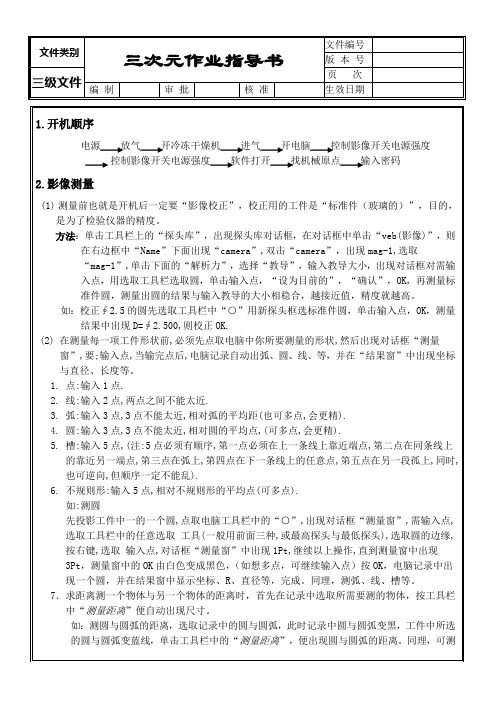
1)测量前也一定要“探头校正”,校正时用的工件是“标准件(¢30球头)”,目的,也是为了检验仪器的精度(注:球头可不用每天校正,为确认精度,也可每天校正)。
方法:单击工具栏上的“探头库”,出现探头库对话框,在对话框中单击“Probes探头”下的“Contactprobes”,然后双击“NAME”下面“TOUCHPROBE”,出现“TPTIP”,选取“TPTIP”,单击下面的“尺寸位移”,选择“教导”,出现对话框,用探头碰4点去测量标准件圆,第一点碰顶点,其它3点碰圆的周边,且相对圆的平均点,3点之后,对话框中的OK由白色变成黑色,按“OK”,出现另一对话框,在另对话框中的“测钻直径”中出现直径大小,此大小尺寸一定要与标准件圆的直径大小相稳合,越接近值,其精度越高,点取对话框中的“设为目前的”,“确认”,OK。
4.探头与影像结合
探头与影像结合,即为两者同步(即座标统一,如:两者同时测一个圆,得出的坐标与大小一样),在两者同步时,必须先把影像校正与探头校正做好。
探头与影像结合的方法:
在“探头库”——PROTES——单击CONTALTPROBES——教导——影像孔(注:取4点)——输入4点后——自动出现对话框,根据对话框中的提示——用探针取前面影像过的孔4点——用探针在平面碰1点——调为目前的——确认——OK。
6.不规则形:输入5点,相对不规则形的平均点(可多点).
如:测圆
先投影工件中一的一个圆,点取电脑工具栏中的“○”,出现对话框“测量窗”,需输入点,选取工具栏中的任意选取 工具(一般用前面三种,或最高探头与最低探头),选取圆的边缘,按右键,选取 输入点,对话框“测量窗”中出现1Pt,继续以上操作,直到测量窗中出现3Pt,测量窗中的OK由白色变成黑色,(如想多点,可继续输入点)按OK,电脑记录中出现一个圆,并在结果窗中显示坐标、R、直径等,完成。同理,测弧、线、槽等。
Mitutoyo PH-A14型号光线投影仪说明书

Optical MeasuringPH-A14 Profile ProjectorQM-Data200 mountedon PH-A14 profileprojector Bulletin No. 1883Projection LensesPH-A14 Horizontal Profile ProjectorFeatures:•Mitutoyo’s lens technology and workmanship combine to provide a bright, crisp image for error free inspection.•The PH-A14’s generous x, y workstage travel (8"x4") provides users with ample range to cover application needs.•New location of the Y-axis handle improves ease of operation.•The workstage provides high accuracy and can handle a workload of up to 100 lbs.•Fiber illuminator is standard accessory.PH-A14comes equipped with Linear Glass Scales factory mounted ready for your choice of optional display counters (shown with QM-Data 200)10X Standard accessory50X20XSpecificationsOrder No.172-810AModel No.PH-A14Projected image Inverted imageProtractor screenDiameter14" (356mm)Material Fine ground glass with cross - hair linesAngle Vernier reading, Resolution: 2'IlluminationContour24V, 150W (512305) halogen lamp,Telecentric illumination Surface24V, 150W (512305) halogen lamp,Twin fiber-optic illuminator Magnifications10X (Standard), 20X, 50X, 100X (Option)Magnifications AccuracyContour0.1% or lessSurface0.15% or lessWorkstage(X-axis)Table travel8" (203.2mm)Table size16" x 6" (407 x 153mm)Reading unit Linear ScaleResolution.00005" (0.001mm)*1 (Y-axis)Table travel4" (101.6mm)Reading unit Linear ScaleResolution.00005" (0.001mm)*1 (Z-axis)Focusing travel2" (50.8mm) XY counter OptionPower supply120VAC, 50/60HzDimension(W x D x H)25.5" x 53.3" x 43.3" (648 x 1355 x 1100mm) Weight335lbs (152Kg)Max Load100lbs (45.37Kg)*1 set by XY counter Standard AccessoriesOrder No.172-011 Projection Lens 10x512305Halogen bulb 24V 150W (500 Hours) 358191Fuse 6A (for 10-120V)384208Fuse 2.5A (for 220-240V)538815Hexagonal wrench 2.512BAC245Spanner wrench 2.5 199MBA025A Operational manualSee the backside for optional accessories17.9" (454)45.6"(1158) 6.2"(158)24.1" (612)48.8" (1240)1Aurora, Illinois(Corporate Headquarters)(630) 978-5385Westford, Massachusetts (978) 692-8765Huntersville, North Carolina (704) 875-8332 Mason, Ohio (513) 754-0709 Plymouth, Michigan (734) 459-2810City of Industry, California (626) 961-9661Kirkland, Washington (408) 396-4428© 2005 Mitutoyo America Corporation, Aurora IL We reserve the right to change specifications and prices without notice.1105-08 • Printed in USA • November 2005QM-Data200Order No.264-141A (Arm-mount model)Resolution .00002"/.00005"/.0001" (0.0005mm/0.001mm)SoftwareStandard geometric element Geometry combination pattern Memory: 1000 elements (max)Dimension7.87" (W) x 11.02" (H) x 3.54" (D)QM Data 200OPTOEYE 200 - Edge Sensor Order No.332-151*Detector Plate required with OPTPEYE 20012AAE671*332-151KA Counter Order No.174-173AResolution.0005"/.0002"/.0001"/.00005"(0.0005mm/0.002mm/0.001mm)Dimension 10.2" (W) x 6.61" (H) x 3.2" (D)*Requires Counter Tray 58AAA407AKA CounterOptional Display UnitsOptional AccessoriesOrder No.Description172-011Projection Lens 10X (Standard)172-012Projection Lens 20X 172-013Projection Lens Set 50X 172-014Projection Lens Set 100X 172-116Standard scale 50mm 172-117Standard scale 2"172-118Reading scale 200mm 172-119Reading scale 8"172-161Reading scale 300mm 172-162Reading scale 12"172-286Green filter172-142Center support 172-143Center support riser 172-132Vertical holder 172-144Rotary vise 172-234V-block64AAA129BMachine stand (W = 23" x D = 45" x H = 20")Weight: 129 lbs (58.53 Kg)Data Processor and Display Counters 264-141A QM Data200 (Arm Mount Type)332-151OPTOEYE 20012AAE671*Detector Plate 174-173A KA Counter 58AAA407A Counter trayOverlay Charts 201305Combination 201306Grid / 15°Protractor 201307Protractor 201308Screw Thread 201491Radius201493Radius / 10°Protractor *Required with OPTOEYE 200Rotary ViseV-Block with ClampVertical HolderCenter SupportCenter Support Riser Green FilterStandard ScalesReading Scales172-144172-234172-132172-143172-116(50mm)172-117(2")172-118(200mm)172-161(300mm)172-119(8")172-162(12")172-286172-142Workpiece dia.: 60mm maxWorkpiece dia.: 50mm maxSet up a thin workpiece easilyClamps a cylindrical workpiece such as a screwWorkpiece dia.: 120mm maxWidens the damping capacity of the center support to a maximum diameter of 240mm.Increases the screen sharpness of the contour image.Used for checking magnifying accuracy.Designed for checking the magnified image of a standard scale.JSAQ-052ISO 9001。
Mitutoyo 2-D 颜色视觉测量系统 Quick Image Series 3说明书

V I S I O N M E A S U R I N G S Y S T E Measy-to-use measurementfunctionalityquality control systemin operational efficiency and productivityThe 2-D Measuring System Designed and Manufactured by MitutoyoSuperior Addition to Your Quality Control SystemPerform Stable, Highly Accurate Measurements Anywhere Within the ScreenStable and Highly AccurateMeasurement of Large WorkpiecesGasketLight alloy die-cast partWithout sub-pixel processingEdge detection accuracy limited by pixel size.Limitation of pixel size removed and edge detection accuracy greatly improved.With sub-pixel processingSub-pixelprocessingSub-pixel processing imageThe highest level of measuring accuracy within the screen in its class Patent registered (Japan)• A ccuracy of ±1.5μm within the screen, repeatability of±0.7μm in high-resolution mode (QI-B Series) and the ability to focus through a wide range of applications.Highly accurate stages• S tages come in various sizes with an accuracy of ± (3.5 +0.02L) μm, letting you perform highly accurate and stable measurements and obtain reliable data for any kind of workpiece.Both a wide view field and high accuracy• S ub-pixel processing enables high-accuracy edge detection.Rigid construction• R obust construction with a maximum load capacity of 20kg (approx. 44 lbs.) and a vertical stroke of 100mm allows large workpieces to be measured.Ultra-long Working Distance of 90 mm• T he 90mm working distance ensures you can focus, even with stepped workpieces, without worrying about collisions.Reliability 240mmHuman Errors Due to Focusing are EliminatedTraceability to National Standards22mmMeasuring of a cylindrical workpieceMeasuring a stepped workpieceUtilizes our in-house-developed Telecentric Optical System Patent registered (Japan, the U.S.A. and Europe)• E rrors due to height are greatly minimized within a depth of focus with steps of up to 22mm. Measurement errors due to human focusing are eliminated.Mitutoyo...Uses calibration artifacts traceable to national standards• M itutoyo has a large collection of standard artifacts whose dimensions are traceable to the national length standards of Japan and the USA. These artifacts are used to calibrate the specialized equipment used in the calibration ofMitutoyo's measuring tools and instruments so traceability to international length standards is established and maintained. Mitutoyo also provides a temperature calibration service that is absolutely essential to high-accuracy length measurement.National Institute of Standards and Technology(NIST)Working standardSecondary standard Secondary standardPrimary National StandardMitutoyo America CorporationA2LA AccreditedScope of Accreditation to ISO/IEC 17025:2005 & ANSI/NCSL Z540-1-1994 &ANSI/NCSL Z540.3-2006Mitutoyo Utsunomiya Measurement StandardsCalibration Center633nm Practical Stabilized He-Ne Laser Interferometer (for standard scale)Vision Measuring System (measuring accuracy)Mitutoyo Kawasaki plant Working standardSimple to Operate with Easy-to-Use Measurement FunctionalityOne-click circle tool One-click box toolHigh-accuracy measurement of a small feature is achieved by the image zoom functionMultiple view-field stitching imageFull (single image) multiple field of view measurement processing and programmingNewUsabilityEntire View of a Large Workpiece Drastically Improves Ease of Operation and Measurement EfficiencyStitching Function• A newly developed correction algorithm stitches multiple images together (multiple image-to-image coupling) while maintaining high-accuracy measurements.After a stitching operation, measurement is easily processed without the need to move the stage.Simple Execution of Multiple MeasurementsEasy-to-Operate Without InstructionOne-click tool• W ith just one click, anyone can easily perform multiple measurements. The outlier removal function automatically eliminates unnecessary measurement points, thus enabling accurate and stable multipoint measurement.EZ mode Design application pending (Japan)• T his mode provides an operation guidance display to guide the operator even if it's their first time performing measurements. This removes the need for continual referenceof the instruction manual during operation.User templateEnhanced rectangle templateQuick-release ringMeasurementfinishedOne-clickAutomatic recognitionThe position and inclination of a workpiece can be measured even if it has movedFocusing in on a stepped workpiece like the one shown above is unnecessary with the telecentric objective.No Troublesome Positioning is RequiredSimple FocusingCapable of Visually Capturing an Entire ImagePerform Quick Measurements Even on Large WorkpiecesOne-click execution function Patent pending (Japan)• A fter placing the workpiece within the field of view, the machine automatically recognizes the position and angle using a pattern search function and then finishes themeasurements. There is no need for positioning and axially-aligning the workpiece.Wide focus range• O ur specifically designed optical system achieves the long focal depth of 22mm. This allows measurement without the time-consuming focusing task, supporting an efficient measurement operation.Graphics function• T he current position, coordinate system, measuring item and measurement result are automatically displayed in a graphics window. The graphics window prevents omissions and errors with the measurements from occurring. 2-D CAD model data can be imported (optional) in order to better capture the actual full image.Quick release mechanism on the XY stage *QI-A series, QI-B series• Q uick-release mechanisms are built into both fine feed controls on the XY stage. This allows the stage to be moved rapidly to bring the next measuring point into view no matter where it is on the workpiece.13.46”(342)9.44”(240)17.71”(450)24.01”(610)Take advantage of the largest stage by performing multiple measurements at one setup.The measurement results display for OK/NG can be color-coded to meet your requirements.User-friendly and Convenient XY Stage MovementNew Lineup of Motor-driven Stage Models * QI-C series• T he joystick provides an easy, convenient control for coarse and fine feed of the stage. This effortless moving of the XY stage demonstrates outstanding performance in long-length measurement. The motor-driven stage automatically moves for stitching by specifying its start and end points.Motor-driven stageDedicated remote boxNewOutstanding Improvement in Operation Efficiency and ProductivityEfficiency Confirm Measurement Results Quickly and EasilyCapable of Supporting a Variety of WorkpiecesVideo window measurement result display function• M easurement results can be understood intuitively just by looking at a measurement image. Any out-of-tolerance result data is easily identified by changing its display color. A graphic image with measurement data also leads to creation of a user-friendly report.• E ach OK/NG result is color-coded with its operator selectable display color.Large-stage model and extensive line up of stages• T he large stage allows you to arrange multiple workpieces and measure them in a single setup, thereby saving valuable time that would otherwise be spent in loading and unloading the stage.• X Y measurement range: Measure workpieces up to 400x200mm.• 100mm Z-stroke allows you to measure tall workpieces.• A maximum load capacity of 44 lbs (20Kg) allows you to measure heavy workpieces.Surface observation of black rubberEdge measurement of a stepped workpiece (high resolution mode)Clear edgesMultiplepattern Measurement of several workpieces done Simple "OK/NG Judgment" of Multiple WorkpiecesSimple Execution of Stored Measurement ProgramsGenerate Reports and Observe All On One MachineMeasure Multiple Workpieces Within the Field of View All at OnceTolerance judgment result display function• O K/NG judgment can be seen at a glance for faster operation.• O K/NG judgment can be done for each measurement item, and judgment can be passed on each workpiece.• P revents NG data omissions.Program launcher• A measurement procedure program can be stored under a dedicated icon along with a photo and comments to enable the required programs to be started easily.• 10 icons are available and programs can be managed for each operator or workpiece.High-definition color camera• T his camera provides high-resolution color images for effective use in high-accuracy measurement and workpiece surface observation. Bright color measurement images are easily stored as a file and can be used for creating an easily understood measurement report.Locate and measure multiple workpieces with just one click• U se pattern search for multiple workpieces within the screen view, and measure them all in one operation with the one-click execution function. This eliminates the need for accurate positioning of workpieces and cumbersome setup of fixtures.Automatic measurement procedure program storage windowProgram launcher iconsHigh Accuracy Measurement with Bright and Clear ImagesWide field of view / high-resolution mode• T he high resolution mode produces the same wide field of view as the normal mode that operates with a deep focal depth. This allows you to share a single measurement procedure so that you can execute seamless measurements.• T he shallow depth of focus in high resolution mode shows the edges of stepped workpieces more clearly, making measurements highly accurate.Enhanced illumination Patent registered (Japan)• T he enhanced illumination function of the high-resolution mode enables measurements of low reflectivity workpieces like rubber and black resin moldings to be performed with a clear image.Progressive Die-pressed PartsMeasuring a Small Stepped Workpiece O-ring / SealsMeasuring a Stepped Workpiece WeatherstripSheet Switch MeasurementYou can see and measure edges easily with just one quadrant of the ring light providing illumination.Measure with simple focusing.The color camera allows enhanced observation and measurement of workpieces. It is best suited to the inspection of printed materials and creation of a report.Measurement ExamplesPowerful Edge Detection Functionality Enables Fast MeasurementOutlier removal Auto trace toolRemoves outliers caused by anomalies such as debris, burrs and chips.Automatically detects the edges of unknown contours and obtains point group data.Point group data lets you perform contour form analysis and design value comparison using FORMTRACEPAK-AP (optional).Simple Execution and Editing of ProgramsSmart editorThis function allows XY-stage target position, illumination condition, etc., to be separately displayed as icons or labels in the list of part programs (automatic measurement procedure programs), thereby simplifying program editing.Editing design values and tolerances according to the dialogStandard Software QIPAKEarly Detection of Process IrregularitiesCentralized process management software: MeasurLinkStatistical data can be displayed in real-time, making early detection of process irregularities possible. Early identification of an out-of-control situation enables rapid remedial action to be taken when necessary. Examples of remedial action• Mold repair or cycle-timing change • Cutting tool adjustment or replacementCAD Model ImportMeasurement support software: QS-CAD I/F2-D CAD model data (DXF-, or IGES-formatted) can be importedinto QIPAK. Conversely, QIPAK measurement results can beconverted into 2-D CAD model data. The design value for each measurement item is automatically entered. Since the graphics window makes the present location easy to identify, the operator can quickly move the stage to a given point in the 2D CAD model.Easy Handling of Sophisticated Dimension and Contour EvaluationsExample of gear contour matching, andFoot SwitchStandard type Order No.: 937179TRigid typeOrder No.: 12AAJ088Stage Adapter SetsV-block with ClampSwivel Center SupportHolder with ClampOrder No.: 172-378 Max. supportable diameter: ø25mmCenter height from mounting face: 38-48mm Dimensions: 117(H)×90(W)×45(D)mm Mass: 0.8kgNote: An adapter set is required.Order No.: 172-197 Can be set to an inclined angle of ±10°, in minimum increments of 1°Max. supportable dimensions:When horizontally positioned: ø80×140mm When tilted at 10°angle: ø65×140mm Mass: 2.5kgNote: An adapter set is required.Order No.: 176-107Maximum clamp length: 35mmDimensions: 62(H)×152(W)×38(D)mm Mass: 0.4kgNote: An adapter set is required.Stage size10102010201730174020176-304Stage adapter—○176-310Stage adapter B○—Note: One set consists of two adapters.Clamping of thin workpieces such as PCBs and pressed parts.Clamping of cylindrical objectsQuick data entry while gripping the handle.These are used when connecting some optional peripherals to the measuring device.Clamping of the workpiece between centers for effective thread diameter and depth measurements.Order No.: Stage adapter : 176-304 Stage adapter B : 176-310Dimensions (1piece): 50(W)×340(D)×15(H)mm Note: The stage adapter B is 280(D).Mass: Stage adapter: 1.5Kg Stage adapter B: 1.2KgSpecificationsRing Light Diffusion PlateEffective on a diffusely reflectiveworkpiece such as a machinedsurface. This plate makes the surfaceappear smooth to obtain an imagesuited to measurement. The workingdistance is 76mm.Order No.:02ATX180*2 The measuring accuracy is guaranteed to be accurate within the depth of focus. *3 For 1X digital zoom (when using the 22-inch-wide monitor)*4 Patent registered (Japan)Manual Stage ModelQI-A1010D/B1010D QI-A2010D/B2010DUnit: Inch mmQI-A3017D/B3017DQI-A4020D/B4020DQI-A2017D/B2017DQI-A seriesQI-B seriesQI-A4020DManual stage modelThe mounting stand(02ATX190) is optional.*V aries depending on position of XY stage.Values in parentheses indicate maximum size.Dimensions ChartMotorized Stage ModelUnit: mmQI-C3017DThe mounting stand(02ATX190) is optional.*V aries depending on position of XY stage.Values in parentheses indicate maximum size.QI-C seriesQI-C2017DMotorized stage modelSensor Systems Test Equipmentand Seismometers Digital Scale and DRO SystemsSmall Tool Instrumentsand Data ManagementMitutoyo America CorporationOne Number to Serve You Better1-888-MITUTOYO (1-888-648-8869)M3 Solution Centers:Aurora, Illinois (Headquarters)Boston, MassachusettsCharlotte, North CarolinaCincinnati, OhioDetroit, MichiganLos Angeles, CaliforniaBirmingham, AlabamaSeattle, WashingtonHouston, Texas5M 0518-02 • Printed in USA • May 2018©218MitutoyoAmericaCorporationFind additional product literatureand our product catalogNote: All inform ation regarding our products, and in particular the illustrations, drawings, dim ensional and perform ancedata contained in this printed matter as well as other technical data are to be regarded as approximate average values. Wetherefore reserve the right to make changes to the corresponding designs. The stated standards, similar technical regulations,descriptions and illustrations of the products were valid at the time of printing. In addition, the latest applicable version of ourGeneral Trading Conditions will apply. Only quotations submitted by ourselves may be regarded as definitive. Specificationsare subject to change without notice.Mitutoyo products are subject to US Export Administration Regulations (EAR). Re-export or relocation of our products mayrequire prior approval by an appropriate governing authority.Trademarks and RegistrationsDesignations used by companies to distinguish their products are often claimed as trademarks. In all instances where MitutoyoAm erica Corporation is aware of a claim, the product nam es appear in initial capital or all capital letters. The appropriatecompanies should be contacted for more complete trademark and registration information.。
