电机系统使用说明书
电机使用说明书

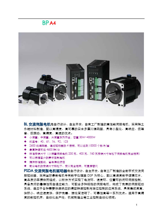
偏航电机使用说明书本手册介绍了YEJ电磁制动三相异步电机的安装及使用方法,请仔细阅读并妥善保管,以使电机能够安全可靠有效的运行。
一.概述YEJ电磁制动三相异步电机用于驱动风力发电机偏航用齿轮箱,电机设计电压及频率为400/690V 50Hz,也可根据用户需要派生制造。
电机非驱动端安装有电磁制动器,用于电机制动,具体使用方法将在本说明书第六部分给出。
电机安装有加热带,工作电压及频率为230V 50Hz。
同时,电机还安装有温度传感器,保护温度为100℃。
二.工作条件1.海拔不超过1000m。
2.运行时环境温度:-40℃~+55℃。
3.相对湿度不超过100%。
4.空气允许含盐且含有细沙。
5.电源电压变化不超过额定值的±5%。
6.电源频率变化不超过额定值的±1%。
7.电机工作制为S3,最长连续运行时间不超过1小时。
三.运输与储存1.装卸及运输中不得拆箱,避免雨淋和剧烈震动。
2.如不立即使用,对电机的轴伸应涂防锈剂或临时性涂封材料,包装箱内需衬油毛毡纸及塑料膜,并加干燥剂。
3.存放地点应清洁,通风良好,不得有腐蚀性气体,环境温度最好不低于+3℃,避免雨淋。
四.安装和使用1.清除机体内的灰尘及轴伸的防锈层。
2.仔细检查各零部件装配是否良好,紧固件有无松动现象。
3.检查导电接触部分是否良好,如有锈斑应清除之。
4.用手轻转电机轴伸,查看转动是否灵活,并细听内部有无摩擦或碰装等杂声。
5.检查电机铭牌数据是否符合要求。
6.用500兆欧表测量绕组相间及对机壳绝缘电阻,若测得的电阻不低于表1即可使用。
低于上述值时,需将电机拆开进行干燥处理,一般情况下保持100~110℃温度烘8~10小时,干燥过程中应做好测量记录,开始每小时测一次,以后每半小时测一次,直到绝缘电阻稳定合格为止。
若无烘干装置,亦可采用通入短路电流的方法进行,此时转子应堵转,定子输入 1.5倍以下额定电流,保持发热温度70~75℃。
表17.检查接地装置是否妥善并接好地线,地线应用裸线。
电机使用说明书

电机使用说明书Operati ng Manual概述本说明书适用于我公司生产的 YX3 YET 丫2、YVP YD 系列低压三相异步电动机及其派 生系列产品OverviewThe manual serves YX3 YET Y2、YVP YDSeries low voltage asynchronous motors and it's derivative products as well.开始使用Putt ing into use (start ing)收货检查Recepti on check收到电机后立即检查是否有损坏,如发现请立即拨打电话:0086-21-6463-1777,或发传真至0086-21-6463-7180,检查铭牌数据特别是额定电压、接线方式(星形或三角形) 是否与合同订货要求相符,用手转动电机轴检查轴转动是否灵活。
Immediately check the motor for exter nal damage upon receipt and if found, please inform us by telepho ne or fax without delay (Tel:0086-21-6463-1777, Fax:0086-21-6463-7180). Check all rating plate data, especially voltage and winding connection (star or delta). Turn shaft by hand to check for free rotati on.绝缘电阻检查In sulatio n resista nee check在电机调试前或怀疑线圈受潮时要测量电机的绝缘电阻, 在25C 时的绝缘电阻值应超过 以下表达式的值,表达式中:Measure the motor's in sulati on resista nee before commissi oning or whe n wi nding damp ness is suspected. in sulati on Resista nee, measured at 25 P = output power, kW.警告.温度每升高20C,绝缘电阻将降低一半,如果绝缘电阻值达不到计算值, 表明线圈已经C, shall exceed the followi ng refere nee value, i.e. where R:单位兆欧(用500V 绝缘电阻表测量) U 表示电压,单位V P 表示功率,单位kWR: M Q ( measured with 500 V dc Megger ) U = voltage, Volts; R=1000+P 100测量完绝缘电阻后应立即将测量线从电机上断开, 以免线圈再次受到高电压冲击。
电机使用说明书

Z4及Z4派生系列直流电机使用说明书上海电机(集团)公司南洋电机厂目录1.一般说明1.1概述1.2轴的承载能力和轴承1.3冷却1.4出线盒2.安装2.1收货和存放2.2安装2.3联轴器或皮带盘的安装2.4校准2.5接线3.开车3.1机械检查3.2绝缘电阻3.3干燥3.4起动3.5静止状态4.维护4.1轴承4.2换向器4.3电刷4.4刷架4.5过滤器装置4.6拆卸和再装配5.接线图1.一般说明1.1概述Z4系列直流电机是在引进西德AEG公司全套设计、制造技术的基础上,通过消化吸收,结合国情自行开发的。
Z4系列直流电机适用于静止电力变流器供电,用在三相桥式可控硅整流电源,一般都不需要外接平波电抗器,用在单相桥式可控硅整流电源,所需的外接平波电抗器的电感值已在样本中给出。
1.2轴的承载能力和轴承标准结构的轴伸是在按联轴器转动,轴伸无附加力下,仅承受圆周力(即额定转矩)下所确定的。
标准传动侧轴伸和轴承的允许附加力(Fr=垂直于轴心线的作用力)在样本中已作出说明,其中轴承的计算寿命为20000工作小时,这些附加力的极限值已考虑了轴伸的疲劳强度,不允许超过。
表中所列出的附加力不包括装于轴上的联轴器、飞轮等质量。
对于非传动侧的付轴伸只允许承受很小的附加力,如需要时可向制造厂询问。
电枢装有向心球轴承。
轴承按照共所条件必须进行再润滑。
在轴承的安装部位处装有一个润滑油嘴。
传动端的轴承构成紧端结构。
作为轴承防外来振动的保护,威力改善运转的稳定性,Z4-200及以下的电机在非传动侧(松端结构)装有一个波形弹簧,波形弹簧的弹性作用使得非传动端的球轴承外圈,或传动端的球轴承内圈在轴向上作微量移动,一消除轴承内的剩余间隙。
1.3冷却自冷却:在自冷却的电机中,传动端装有风叶,冷风从非传动端径向进入,并通过电机被吸出。
空气的排出同样是径向的。
为了在空气污染严重的室内达到较高的防护形式,在非传动端,冷风可以通过管道吸入。
空气的排出可以不采用管道,也可以采用管道(IPR44),在使用管道时,应有充足的载面,尽量避免弯曲,必要时须了解一下的风压值。
伺服电机使用手册
不要接触电机、驱动器、制动电阻, 因为它们是发热部件
否则可能导致灼伤
不要接触运转中电机的转动部分 否则可能导致人身伤害
不要更改、拆卸或自行修理电机或 驱动器
否则可能导致触电事故,导致人身伤害
搬运电机时,不要提拉电缆或电机 轴部
否则可能导致器件损坏
在电源故障排除后,设备有可能突 然重新启动,所以不要靠近设备
备注:请勿按照电机端电源出线的线径选择电机电源电缆的线径,因为该线属于高温导线,尽管线径小,但
可以通过要求的电流。
4.2
运动随心,控制所欲
8
4.3 4.4 驱动器技术参数
伺服电机使用手册
运动随心,控制所欲
9
4.5 电机电源线接线定义
伺服电机使用手册
电机
电机型号
插头类型
40 型电机 57 型电机 76 型电机 92 型电机 123 型电机
3 4
控制线 编码器线
双绞屏蔽线
控制器至驱动器的控制线长度<3 米 驱动器至电机的编码器线长度<20 米
5
接地线
尽量使用粗导 线
接地电阻<100Ω 的一点接地方式
如电机与机床之间是 处于绝缘状态,请将 电机接地
6
模拟信号 屏蔽线
请注意终端联接
7
制动电阻
良好连接,良好通风
8
保持制动器
需要配浪涌吸收电路
4.1.2 驱动器安装注意事项
安装位置:室内,无水、无粉尘、无腐蚀气体、良好通风; 如何安装:垂直安装,通风良好; 安装到金属的底板上 如可能,请在控制箱内另外安装通风风扇 驱动器与电焊机、放电加工设备等使用同一路电源,或驱动器附近高频干扰设备,请采用隔离变压器 和有源滤波器 请将驱动器安装在干燥且通风良好的场所; 请尽量避免受到振动或撞击; 尽一切可能防止金属粉尘及铁屑进入驱动器内; 安装时请确认驱动器固定,不易松动脱落; 接线端子必须使用带有绝缘保护; 在断开驱动器电源后,必须间隔 10 秒钟后方能再次给驱动器通电,否则频繁的通断电会导致驱动器 损坏; 在断开驱动器电源后 1 分钟内,禁止用手直接接触驱动器的接线端子,否则将会有触电的危险! 当在一个机箱内安装多个驱动器时,为了驱动器的良好散热,避免相互间电磁干扰,建议在机箱内采 用强制风冷,请采用如下示意图进行安装
电机使用说明书
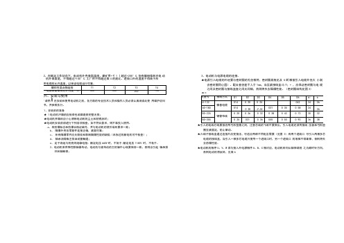
2、在额定工作状态下,电动机外壳表面温度,煤矿用+彳1丨超过+200°C,但有煤粉堆积在电动机外表面是,不得超过+150°C,工厂用不得超过表4的规比。
进线口外的温度不得高于所3、电动机与电源电缆的连接。
★电源引入电缆的外经要与密封圈的孔径相符,密封圈规格见及5(町根据引入电缆外径大小剥去密封圈同心圆)。
配合直径差不人于1mm,当压紧接线盒斗/T;•,应保证密封圈与电缆之间及密封圈与接线盒座之间无间隙,否则将失去隔爆性能。
(密封圈结构见图3)表5'请用A在安装和使用电动机之前,各方面的专业技术人员和操作人员必须认真阅读此使用维护说叫书,并参照执行。
1、安装前的准备★ 1电动机汗箱前应检杳包装箱是否完整无损;★电动机开箱后应小心淸除电动机的尘土和防锈涂封;★电动机安装前须进行下列各项检查,如不符合耍求,则不准投入使用。
.a、有防爆标志和防爆合格证编号,并与电动机的使爪场所要求一致;b、隔爆外壳各零部件连接正确,紧固可靠;c、所有隔爆零件应无裂纹和影响隔爆性能的缺陷(未拆过的新电机可不检查);d、轴承润滑脂注排油装置畅通;e、定子绕组与机壳间绝缘电阻:额定电压660V时,不低于;额定电压1140V 时,不低于。
2、电动机采用弹性联轴器传动,电动机与被传动的主机轴中心线要保持一致,否则会引起轴承损坏和轴断裂。
★引入的电线芯线要接在两弓形垫圈之间,注意芯线的飞刺不要突出,引入电缆还须用接线压板和弓形垫圈压紧固定,防止窜动。
★六端子接线盒通过连接片改变接法,可适应两种不同电压需要(见图3),有两个进线口可引入两根多芯电缆的接线盒,当引入一根多芯电缆只使用一个进线口时,另一个进线口的堵棒不得拿掉,否则将失去防爆性能。
★电动机的相序U、V、W须与接入外电源相序A、B、C相对应,电动机转向从轴伸端视之为顺时针方向,否则电动机将反转,见表6Y接U2产品使用维护说明书表6★电动机接线U,经检汽确认无误后方可接通电源进行空载试运转,并观察电机打尤片常现象,待9转正常后投入负荷运行。
多功能电机控制器使用说明书
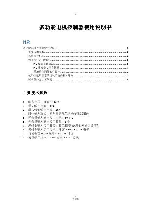
多功能电机控制器使用说明书目录多功能电机控制器使用说明书 (1)主要技术参数 (1)系统硬件构造 (2)伺服软件系统构造 (6)PID算法设计思路 (6)PID滤波器C语言代码 (7)系统通信局部软件设计 (9)使用快速原型系统调试系统的根本思路 (10)驱动器外壳加工问题 (11)主要技术参数1.输入电压:直流18-60V2.最大输出电流:10A3.最大峰值输出电流:20A4.限位输入形式:霍尔开关限位滑动变阻器限位5.开关量输入输出接口电平:5V TTL6.开关量输入输出接口数量:8个7.编码器输入接口种类:相位相差90度的双路方波信号8.编码器输入接口电平:兼容3.3V,5V TTL电平9.电机驱动PWM频率:1K-72K可调10.通信接口形式: CAN总线RS232总线系统硬件构造核心控制电路硬件构造USB和以太网由于空间现在本系统中功能被屏蔽。
USB接口可以实现系统的在线更新和维护。
基于实时以太网的高速控制器为伺服电机控制器开展的趋势〔西门子和法兰克的数控系统都采用这种方式〕,对于分散式控制系统,这种控制方式可以省略掉入XX控制系统中购置多串口卡的本钱;并且,由于网络变压器的隔离特性,即使下层电路在未来的设计中不采用隔离设计,整个系统对于工业控制计算机仍然是隔离的,实用此种方法可以提高系统的稳定性,降低整个系统的本钱,并实现控制系统固件库的在线远程更新。
以上两种功能可以在新的电路板设计中增加。
系统的多功能输入输出构造中预留绝对式磁栅编码器的接口单元。
启动模式根据使用说明书在系统的默认条件下,从主储存器启动,即BOOT0引脚位低,这种情况适合系统通过仿真器调试时使用。
这种启动模式也是默认值。
即在电路板中左部的BOOT0和BOOT1不连接任何短路冒。
这样设计的目的是要早工业应用场合防止使用短路冒造成系统在震开工况下不稳定的情况。
如图1.1 所示。
图1.1 从主FLASH启动的默认设置如果系统需要有在线更新功能,本主控板可以通过USART2,USB OTG FS对系统进展更新。
电动机说明书(上海电机)

4. 检查及维护4.1 引言——为了保证连续安全可靠使用,必须制定维护大纲。
4.2 电动机在运行时的常规检查上海电机厂建议要经常检查润滑油系统。
应检查所有油位表中的油位。
通过油环视察窗查看油环的旋转情况。
如果发现漏油,应追查根源并加以纠正。
监视润滑油的变色及污染情况。
注意任何噪声或振动的突然增大或过大,并应迅速纠正。
在连续运行期间定期检查轴承温度,检查定、转子之间的间隙,清理集电环和刷架上的积灰和油污,至少每星期一次。
4.3维护计划4.3.1 对于一般的使用条件,推荐以下维修计划。
4.3.1.1 在提供的测温装置处测量温度,它们时为了测量定子绕组、冷却空气及轴承的温度。
(例如埋入式电阻测温元件)。
4.3.1.2 查听整个电动机是否有不正常的机械噪声或者出现变化的响声(例如摩擦或敲击声等)。
4.3.1.3 当具有水——空气交换器装置时,用目检查水管是否漏水。
4.3.1.4 当采用过滤器装置时,检查过滤器的沾污程度。
4.3.1.5 用手检查或用温度计(如果装有)在测温装置处测量并记录轴承温度。
检查定、转子之间的间隙,清理集电环和刷架上的积灰和油污。
4.3.2 每月的检查。
4.3.2.1 用轻便型测量设备测量振动。
测量点位置在轴承室中部。
4.3.2.2 检查所有电缆,联接线及其紧固情况。
4.3.2.3 如果是线绕式转子,检查在滑环、导电螺杆及电刷装置上灰尘沉积的程度。
需要时清除沉积的灰尘。
检查电刷的摩损及在刷握中自由活动的情况。
如果需要,则更换电刷。
4.3.2.4 当具有过滤器装置时,在过滤监视器动作后(例如压差开关)则应更换或清理过滤器。
4.3.2.5 在油润滑的轴承中,检查油环运转是否平稳以及带油情况。
检查轴承密封是否漏油,如果已弄脏,则清除脏物。
检查供油设备。
4.3.3 每季的检查。
4.3.3.1 测量定、转子绕组的绝缘电阻。
4.3.3.2 用一只额定电压为500至625伏的兆欧计测量绝缘的轴承或座与钢的基础之间的绝缘电阻。
A8说明书

否则可能导致受伤。
请勿使用设置在主电源上的电磁接触器进行 电机的运转和停止操作
否则可能导致故障发生。
请勿使用爬至机器上或在其顶部放置重物
否则可能导致触电、受伤、故障、产品损坏。
切勿强烈撞击设备
否则可能导致故障发生。
切勿对驱动器进行极端的增益调整和变更 勿使机械的运转发生不稳定的情况
请勿将电机的内部保持制动器用于停止电机 运转负载(制动)
否则可能导致灼伤。
请勿在电机、驱动器、再生放电电阻附近放置 易燃物
否则可能会引发火灾。
请勿将控制器设置在电炉或大型线圈电阻器 等发热体附近
否则可能会引发火灾或导致故障发生。
必须设置过电流保护器、漏电断路器、过热保 护器、紧急制动器
否则可能导致触电。
在外部设置紧急制动器,以便在发生紧急情况 否则可能导致受伤、触电、引发火灾、故障或 产品
排除电源故障后,设备可能重新驱动, 切勿靠近设备, 请对机械进行设置,使其重新启动时也能确保 人身安全
否则可能导致受伤。 否则可能导致受伤或故障发生。 否则可能导致受伤。
切勿进行改造,拆卸或自行修理
否则可能导致触电或引发火灾和受伤。
请勿过度用力拉拽电缆
否则可能导致故障发生。
请使用指定配套型号的电机
否则可能引发火灾。
6
A8 系列伺服电机系统使用手册
3. 安装和配线
3.1.电机安装注意事项
u 安装位置:室内,无水、无粉尘、无腐蚀气体,良好通风; u 如何安装:电机可以水平或垂直安装,当水平安装时,请把电缆出口朝下,以免进油进水;垂直安装时,如果配有机
械装置,必须取保机械装置的油水不得进入电机; u 禁止敲打电机后端盖,以免损坏电机的光电编码器; u 请尽量使用弹性联轴器; u 尽量避免敲打电机的轴端,以免损坏电机的轴承和后端的编码器; u 需注意电机轴端的轴向和径向负载不要过大;
三相异步电动机使用说明书

5.1.1.2、检查和清擦电动机接线端子:检查接线盒接线螺栓(母)是否松动,拧紧螺母, 必要时更换。 5.1.1.3、检查各固定部分螺栓(母)和接地线:检查接地螺栓(母),检查端盖、轴承 内外盖紧固螺栓,检查接地线连接及安装情况。 5.1.1.4、检查轴承:拆下轴承盖,检查轴承润滑脂是否变脏、干涸,缺少时须适量补充, 检查轴承是否有杂音,必要时更换。 5.1.1.5 检查传动装置:检查电机风扇有无破裂损坏,安装是否牢固,紧固螺栓(母)是 否松动、损伤、磨损和变形,必要时更换。 5.1.2 年维修或大修内容 5.1.2.1 年维修或大修内容包括月维修或小修内容: 5.1.2.2 电动机外部检查:检查外部有无损坏,零部件是否齐全,彻底清擦,去掉尘垢, 补修损坏部分。 5.1.2.3 电动机内部清理和检查 (a)检查定子绕组污染和损伤情况,先去掉定子的灰尘,擦去污垢,若定子绕组积留油 垢,先用干布擦去,再用干布沾小量汽油擦净,同时仔细检查绕组绝缘是否出现老化痕 迹或有无脱落,若有,应补修、刷漆; (b)检查定、转子铁心有无磨损变形,如有变形,则应予修整。 5.1.2.4、绕组检查 (a)检查定子绕组和转子绕组是否有相间短路,匝间短路、断路等现象,脱焊,烧坏等 现象,应针对发现的问题予以修理; (b)用兆欧表测量所有带电部位绝缘电阻,阻值应大于 1MΩ。 5.1.2.5、清洗轴承并检查轴承磨损情况: (a)用盛有汽油的容器来回搅动轴承多次,随后用手握住轴承内圆,转动外圆,在转动过 程中,放在另一盛有汽油容器中清洗,轴承安装时,允许采用热套法,加热时,机油温 度不得超过 100℃,而且轴承应得到均匀加热; (b)检查轴承,检查轴承表面粗糙和滚珠或轴圈等处,若出现兰紫色,说明轴承已受热退 火,严重者应更换轴承; (c)有条件对轴承内径、外径、宽度的尺寸进行测量。 5.1.2.6 维修后试车:若电动机绕组完好,大修后要做一般性试运转,测量绝缘电阻, 检查各部分是否灵活,电动机空载运转半小时,然后带负载运转。 5.2 电动机运行时,轴承温度应不高于 95℃(温度计法),轴承运行 2500h 至少检查 一次,若出现润滑脂变质时,必须及时更换。清理轴承内、外盖注排油装置内的废油, 达到干净、畅通,轴承需用汽油清洗干净。轴承装配时,直接添加润滑脂,2P 规格电机
SIMOCODE pro 电机管理系统说明说明书

2The highlights of SIMOCODE pro• E xtensive protection, monitoring and control functions, independent of the automation system • D etailed operational, service and diagnostics data – at any time or place • Safe shutdown of motors• S calable, flexible solutions for all plant configurations• V ersatile, open communication via various bus systems and protocols • I ntegration in process control systems such as SIMATIC PCS 7• Supports PROFINET system redundance and dynamic reconfigurationSIMOCODE pro offers multifunctional, solid-state full motor protection. The motormanagement system monitors, protects and controls constant-speed motors and enables the implementation of predictive maintenance. It does not wait for a prob-lem to occur before shutting down the motor, but establishes a level of transparency in advance. This avoids plant standstills and improves economic efficiency. SIMOCODE pro delivers detailed operating, service and diagnostic data from across the entire process. The engineering is simple and likewise the integration into pro-cess control systems. SIMOCODE pro communicates via PROFIBUS and PROFINET, Modbus, EtherNet / IP and OPC UA. It implements simple and economical motor management.With both the SIMOCODE pro General Performance and SIMOCODE pro High Perfor-mance device classes, we offer scalable, flexible solutions for industrial controls and plant optimization in the context of Industrie 4.0.For 30 years now, SIMOCODE pro has been controlling and moni-toring low-voltage, constant-speed motors all over the world. Wherever motors keep things running in the process industry,SIMOCODE is there. Many thousands of times over. Now even more powerful thanks to connection to the Cloud.Flexible, modular, integrated.The way modern motor management should be.3Two functionally graded device series form the core of the multifunctional SIMOCODE pro motor management sys-tem: General Performance and High Performance. The de-vices in both series incorporate all essential motor protec-tion, monitoring and control functions – including data transparency through the Cloud connection. SIMOCODE pro General Performance is your entry into modern motor management and addresses standard motor applications. SIMOCODE pro High Performance features up to five expan-sion modules and offers additional measured variables. Find out how you can take advantage of the two SIMOCODEpro device series in all areas of the process industry.SIMOCODE pro. A really strong family.SIMOCODE pro –General Performance:Ideal for the entry levelThe smart and compact motor management system for direct-on-line, reversing, and star-delta (wye-delta) starters or for controlling a motor starter protector or soft starter. The basic system includes a current measuring module and the basic unit for overload or thermis-tor motor protection, for example. Communication with the automa-tion level takes place via PROFIBUS/ PROFINET. Optional additions in-clude an operator panel and an expansion module that allows additional inputs/outputs, ground-fault detection and temperature measurement to be realized. SIMOCODE pro – High Performance:The fully professional solutionfor every motorThe SIMOCODE pro High Perfor-mance motor management systemis variable, intelligent and can beadapted individually to suit everyrequirement. The basic systemincludes a module for measuringcurrent (and optionally also volt-age), as well as a basic unit, and issuitable for removing pump block-ages, for example. Communicationwith the automation level takesplace via PROFIBUS or Modbus RTU,via Ethernet with the PROFINET orEtherNet/IP protocols, and also viaOPC UA. The optional expansionsavailable include separate current/voltage measuring modules fordry-running protection, an operatorpanel with display, a ground-faultmodule, a temperature module,standard digital modules, fail-safedigital modules and an analogmodule.SIMOCODE pro Safety:Fail-safe expansion modulesVarious modules are available forSIMOCODE pro for the extendedprotection of personnel, machinesand the environment. These guar-antee the safety-related shutdownof motors and meet all the require-ments of the standards.The advantages:• F unctional switching andfail-safe shutdown withoutmanual wiring or additionaleffort• S afety function parameterscan be flexibly configured• T ransfer of meaningful diag-nostic data to thecontrol system• L ogging of errors for detailedevaluation• Fail-safe shutdown viaPROFIsafe5S IMOCODE pro –The advantages at a glance• M inimized downtimes – with less maintenance work• E nergy and cost savings over the entire plant life cycle • S imple use • S calable solution• A choice of networked or autonomousconfigurationRemove pump blockages and increase availability.6Every water utility is familiar with the prob-lems of a blocked pump – and the possible consequences: environmental harm, damage due to flooding, and dangers to health as a result of lifting and cleaning pumps. This is compounded by the financial impact of plant downtimes. SIMOCODE pro monitors the current and active power of the pump motor – and derives the pump status from them. If a defined threshold value is exceeded, SIMOCODE pro autonomously reverses the rotational direction of the pump in order to dislodge deposits on the impeller blades, for example.Say goodbye to blocked pumps with SIMOCODE pro – the modular, com-pact motor management system that tackles the challenge by auto-matically reversing the pump. An-other benefit: SIMOCODE pro can be retrofitted in existing plants.Reliable dry-running protection is a must in many applications in the chemi-cal industry. SIMOCODE pro reliably prevents the dry running of centrifugal pumps in order to preclude hazardous situations – and completely rede-fines dry-running protection for pumps in hazardous areas with an innova-tive solution.Sensors on centrifugal pumps in hazardous areas are often prone to fault and are thus high-mainte-nance. The solution: Using active power-based dry-running detection, SIMOCODE pro monitors the active electrical power consumption of the pump motor and thus the status of the pump – without the need for additional monitoring devices or sensors to be installed. The new technology ensures reliable explosion protection in accordance with ATEX and IECEx criteria and saves costs and time for commis-sioning and maintenance.Your benefits through active power-based dry-running protection• Earlier fault detection – D irect conclusions concerning the flow rate can be drawn from the active power consumption of the pump motor – R eliable prevention of dry running of the pump and therefore less damage to the pump • Cost and time savings – N o maintenance effort due to the elimination of mechanical wear of the sensors –No additional sensor required • Reduction of hardware – N o need for additional sensors and mechanical components –Simplified engineering• Reliable monitoring of the system–Compliance with ATEX and IECEx criteria – R eliable and automatic pump shutdown in the event of inadmissible operating conditionsReliable monitoring. Dry-running protection reconceptualized.7SIMOCODE pro with OPC UABenefitsMindSphere8BenefitsSIMOCODE pro is your reliable data supplier for maximum process quality. The motor management system offers:• Data analysis and simulation • S ecure data storage and transmission • Visualization and recommendation(s)• I ncreased availability of components • Optimization of energy consumption • Maximization of process efficiency • Support of PROFINET system redundance and dynamic reconfigurationFor diagnostics and simple configuration, including in the TIA Portal: SIMOCODE ESSIMOCODE ES provides you with the software for the con-figuration, startup, operation and diagnosis of SIMOCODE pro. The software is based on the central Totally Integrated Automation Portal (TIA Portal) engineering framework, pro-viding an integrated, efficient and intuitive solution for all automation tasks. SIMOCODE ES offers you a host of advan-tages, including convenient configuration in the device view, graphical commissioning using drag and drop functions, mass engineering, presentation of signal states online, or clear measurement curves for diagnostic purposes.The convenient way to optimum process guidance: The integration of SIMOCODE pro into SIMATIC PCS 7Using standardized blocks and faceplates, SIMOCODE pro can very easily be integrated into the SIMATIC PCS 7 process con-trol system. This makes it extremely easy to integrate service and diagnostic data from the motor management system into higher-level process control systems, for example.The result: A high level of transparency throughout the plant, enabling faults to be detected at an early stage or prevented from occurring altogether. In general, the greater density of information in the control system enables you to achieve not only greater transparency, but also higher pro-cess quality.Support of redundance mechanisms and dynamic recon- figuration (device extension during ongoing operation) in-creases the plant availability.9SIMOCODE pro system overview – General PerformancePublished by Siemens AGSmart Infrastructure Electrical ProductsWerner-von-Siemens-Str. 48–50 92224 Amberg GermanyFor the U.S. published by Siemens Industry Inc.100 Technology Drive Alpharetta, GA 30005 United StatesArticle No. SIEP-B10327-00-7600 Printed in GermanyWS 09221.0 Dispo 25600SoftwareSubject to changes and errors. The information given in this document only contains generaldescriptions and/or performance features which may not always specifically reflect those described, or which may undergo modification in the course of further development of the products.The requested performance features are binding only when they are expressly agreed upon in the concluded contract.SIMOCODE is a registered trademark of Siemens AG. Any unauthorized use is prohibited. All other des-ignations in this document may represent trademarks whose use by third parties for their own purposes may violate the proprietary rights of the owner.© Siemens 2022SIMOCODE ES (TIA Portal) V18 BasicBasic functional scope including Professional Trial LicenseBoth software and documentation can be downloaded for free, see:https:///cs/ww/en/view/109811683SIMOCODE ES (TIA Portal) V18 ProfessionalFloating license for one user• L icense key on USB flash drive, SW on DVD 3ZS1322-6CC16-0YA5 • L icense key and software download 3ZS1322-6CE16-0YB5 Upgrade for SIMOCODE ES 2007 Premium 3ZS1322-6CC16-0YE5Software Update Service3ZS1322-6CC00-0YL5SIMOCODE pro block library for SIMATIC PCS 7 Version V9.1 with Advanced Process Library (APL)Engineering software V9.1 (OSD)3ZS1632-1XE04-0YA0Runtime license V9.1 (OSD)3ZS1632-2XE04-0YB0Upgrade for PCS 7 block library SIMOCODE pro V8 or V9.0 (OSD)3ZS1632-1XE04-0YE0Upgrade for PCS 7 block library SIMOCODE pro V7 (without APL)3ZS1632-1XE04-0YF0SIMOCODE pro block library for SIMATIC PCS 7 Version V9.0 with Advanced Process Library (APL)Engineering software V9.0 (OSD)3ZS1632-1XE03-0YA0Runtime license V9.0 (OSD)3ZS1632-2XE03-0YB0Upgrade for PCS 7 block library SIMOCODE pro V83ZS1632-1XX03-0YE0SIMOCODE pro block library for SIMATIC PCS 7 without Advanced Process Library (APL)。
HOBBYWING 高功率锋电机系统用户指南说明书
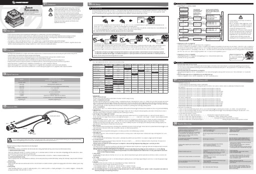
0106ESC SetupSet throttle range1• The timing has been permanently set to 0 degree. With the identical competition motor, this ensures that every driver will have the same power system and have a really just race.• Aluminum housing top with excellent heat dissipation and great current endurance.• The built-in capacitor avoids the trouble of finding installation position for the external capacitor module, saves space and is convenient for layout;• The built-in reverse connection protection circuit prevents damaging ESC due to reverse connection of battery.• The innovative capacitor overheat protection function can effectively avoid the capacitor explosion caused by overload and finally damage the ESC.• Multiple protections: battery low-voltage cutoff protection, over temperature protection, fail safe (throttle signal loss protection) and motor lock-up protection.• Supports multi-function LCD program box and OTA programmer to set parameters of ESC, which is convenient for outside use.• Supports firmware upgrade of ESC (Multi-function LCD program box or OTA Programmer need to be purchased), Enjoy the latest features permanently.• Supports various RPM limit values to meet the needs of different races. It can be set directly by the program box or OTA programmer, which is simple and convenient.Please wire correctly according to wiring instructions and wiring diagram.1. Motor WiringThe sensored motor wiring is a little different from the sensorless motor wiring; please make sure that you will strictly follow the introductions below.A. Sensored Brushless Motor WiringThere is strict wiring order from the ESC to the motor, the three A/B/C ESC wires must connect to the three A/B/C motor wires correspondingly and then connect the ESC sensorport and the motor sensor port with the stock 6-pin sensor cable.Note 1: If you don’t plug the sensor cable in, your ESC will still work in sensorless mode. It is like the ESC connects to sensorless brushless motor.B. Sensorless Brushless Motor WiringThere is no polarity on the A/B/C wires between ESC and motor, so do not worry about how you connect them initially. You may find it necessary to swap two wires if the motorruns in reverse.2. Receiver WiringPlug the throttle control cable (also called Rx cable) on the ESC into the throttle (TH) channel on receiver. So please do not supply power to the receiver. Otherwise, your ESC maybe damaged.3. Battery WiringConnect the battery when the ESC is power off. Make sure positive (+) of ESC connects to positive (+) of battery, and negative (-) of ESC connects to negative (-) of battery whenyou plug in your battery! Then turn on the ESC to run it.You must reset throttle range when you begin to use a new ESC, or the transmitter changes the parameters such as the TRIM, D/R, EPA and other parameters, otherwise the ESC cannot work properly.Programmable Items2Those "black background and white text" options are the factory default settings.1. Running ModeOption 1: Forward with BrakeThe vehicle can go forward and brake but cannot reverse in this mode. This mode is usually for racing.Option 2: Forward/Reverse with BrakeThis mode provides the braking function, it’s usually for training. “Forward/Reverse with Brake” mode adopted the “DOUBLE-CLICK” method, that is your vehicle only brakes (won’t reverse)when the 1st time you push the throttle trigger from neutral zone to backward zone. If the motor stops when the throttle trigger quickly return to the neutral zone and then re-push thetrigger to backward zone, the vehicle will reverse. If the motor does not stop, then your vehicle won’t reverse but brake, you need to return the throttle trigger to the neutral zone and pushit to backward zone again. The vehicle only reverses after the motor stops. This method is for preventing vehicle from being accidentally reversed.Option 3: Forward/ReverseThis mode used the “SINGLE-CLICK” method to make the car go backward. When you move the throttle trigger from neutral zone to backward zone, the car will go backward immediately.2. Drag Brake ForceDrag brake is the braking power produced when releasing the throttle trigger to neutral zone. This is to simulate the resistance applied by carbon brush of the brush motor to rotator ofmotor while coasting.(Attention! Drag brake will consume much power, so please apply it cautiously.)3. Cutoff Voltage (or Low Voltage Cutoff Threshold)The ESC will monitor the battery voltage all the time, on ce the voltage is lower than the threshold value, the ESC will reduce the power to 50% and cutoff the power output in 10seconds. When enters into voltage pr otection, the RED LED will single flash that repeats (☆, ☆, ☆, ☆…….). Please set the “Cutoff Voltage” to “Disabled” if you are using NiMH batteries.4. Start Mode / PunchYou can choose the punch from level 1 (very soft) to level 9 (very aggressive) as per the track, tires gripping, your preference and etc. This feature is very useful for preventing tires fromslipping in the starting-up process. In addition, “level 7”, “level 8 and “level 9” have strict requirement on battery’s discharge capability. It may affect the starting-up if the batterydischarges poorly and cannot provide large current in a short time. The car stutters or suddenly loses power in the starting-up process indicating the battery’s discharge capability is notgood; you need to reduce the punch or increase the FDR (Final Drive Ratio).5. Max. Brake ForceThis ESC provides the proportional braking function; the braking effect is determined by the position of the throttle trigger. The max. brake force is produced when the throttle trigger is at thebrake bottom position. Please select the max. brake force parameter as per your car condition and your preference.6. Max. Reverse ForceDifferent reverse amount will bring different reversing speed. For the safety of your vehicle, we recommend using a low amount.7. Initial Brake ForceIt also called min. brake force. It refers to the brake force applied to the motor at the initial position. It seems like point brake. The default value is equal to the drag brake force, so as toform a soft brake effect.8. Throttle Neutral RangeAs not all transmitters have the same stability at “neutr al position”, please adjust this parameter as per your preference. You can adjust to a bigger value when this happens.9. ESC Thermal ProtectionThe output from the ESC will be cut off with the value you have preset. The GREEN LED flashes (☆, ☆, ☆) when the ESC temperature reaches to the preset value. The output will notresume until the ESC temperature gets down.Warning! Please do not disable this function unless you’re in a competition. Otherwise the high temperature may damage your ESC and even your motor.10. Motor Thermal ProtectionAfter enable this function, the output will be automatically closed when the motor temperature reaches the preset value. The green light flashes until the temperature drops to restore theoutput. When the motor is overheated, the green light will flash twice in cycle.Warning! Please do not disable this function unless you’re in a competition. Otherwise the high temperature may damage your motor and even your ESC. For non-Hobbywingmotor, the ESC may get this protection activated too early/late because of the different temperature sensor inside the motor. In this case, please disable this function andmonitor the motor temperature manually.11. Motor RotationIt is used to adjust the rotation direction of the motor (in CW or CCW), that is, when the forward throttle is given, and the rotation direction of the motor is reverse, it can be set to theopposite direction.12. BEC VoltageThe BEC voltage can be adjusted at 6.0V and 7.4V. The normal steering servo is generally set at 6.0V, and the high-voltage steering servo can be set at 7.4v. Select the appropriate voltageaccording to the steering servo used.13. RPM LimitIt is used to set the max. RPM value of the motor. Set corresponding values according to competition rules.This parameter has two choices according to different versions of ESC used:1. If use Hobbywing’s Standard ESC(XR10 Justock G3), then select rpm limit of “Standard” in the table.2. If use Hobbywing’s Handout ESC(XR10 Justock G3-Handout Spec), then select rpm limit of “Handout” in the table.Note: Since the handout spec motor is a four pole design, the actual mechanical rpm of the motor corresponding to the "Handout" column in the parameter table needs to beobtained by dividing the corresponding rpm value by 2.ESC Programming3(For detailed information, please refer to the user manual of the LCD program box.)You can use LCD program box to set parameters, or connect LCD program box with computer to set parameters (use HOBBYWING USB LINK software). Connect the ESC and LCD program boxthat. Press “ITEM” and “VALUE” button to change the parameters. Press “OK” button to store the parameters to your ESC.1. Programming your ESC with the SET buttonPlug the programming cable of OTA Programmer to the programming port of ESC. Then use the mobile phone to installHOBBYWING HW LINK App to set parameters.07Explanations for Different Status LEDFactory Reset41) Restore the default values with the SET buttonPress and hold the SET button for over 3 seconds anytime when the throttle trigger is at the neutral position (except during the ESC calibration and programming) can factory reset yourESC. RED & GREEN LEDs flash simultaneously indicating you have successfully restored all the default values within your ESC. Once you power the ESC off, and then back on, your settingswill be back in the default mode.2) Restore the default values with a multifunction LCD program boxAfter connecting the program box to the ESC, continuously press the “ITEM” button on the program box until you see the “RESTORE DEFAULT” item, and then press “OK” to factory resetyour ESC.3) Restore the default values with a OTA Programmer(Use HW LINK mobile phone App)Connect OTA Programmer to the ESC, enter into 【Parameters】, click “reset” to factory reset your ESC.1. The throttle is in neutral zone1) In normal Blinky mode (non-rpm limit mode), the red LED flashes rapidly.2) In the RPM limit mode, there are two different flashing modes due to two versions of XR10-Justock G3 and XR10-Justock G3 Handout Spec, the details are as follows:XR10-Justock G3:In RPM limit mode, when RPM limit is 25,000, the red LED long flashes once and the green LED flashes once.In RPM limit mode, when RPM limit is 22,500, the red LED long flashes once and the green LED flashes twice.In RPM limit mode, when RPM limit is 20,000, the red LED long flashes once and the green LED flashes three times.In RPM limit mode, when RPM limit is 17,500, the red LED long flashes once and the green LED flashes four times.In RPM limit mode, when RPM limit is 15,000, the red LED long flashes once and the green LED flashes five times.In RPM limit mode, when RPM limit is 12,500, the red LED long flashes once and the green LED flashes six times.XR10-Justock G3 Handout Spec:In RPM limit mode, when RPM limit is 47,500, the green LED long flashes once and the red LED flashes once.In RPM limit mode, when RPM limit is 35,000, the green LED long flashes once and the red LED flashes twice.In RPM limit mode, when RPM limit is 30,500, the green LED long flashes once and the red LED flashes three times.In RPM limit mode, when RPM limit is 25,500, the green LED long flashes once and the red LED flashes four times.In RPM limit mode, when RPM limit is 22,500, the green LED long flashes once and the red LED flashes five times.In RPM limit mode, when RPM limit is 20,000, the green LED long flashes once and the red LED flashes six times.2. The throttle is in non-neutral zone1) The RED LED turns on solid when moving forward. Green LED is also on when throttle trigger is at the end position of forward(100% throttle,on non-speed limit mode).2) The RED LED turns on solid when you brake. The GREEN LED will also come on when pushing the throttle trigger to the full brake endpoint and setting the “Max. Brake Force” to 100%.3) The RED LED turns on solid when you reverse your vehicle.3. LED status when some Protection is Activated:1) The RED LED flashes a short, single flash that repeats (☆-, ☆-, ☆-) indicating the low voltage cutoff protection is activated.2) The GREEN LED flashes a short, single flash that repeats (☆-, ☆-, ☆-) indicating the ESC thermal / overheat protection is activated.3) The GREEN LED flashes a short, double flash that repeats (☆-☆-, ☆-☆-, ☆-☆-) indicating the motor thermal /overheat protection is activated.4) The GREEN LED flashes a short, five times flash that repeats (☆-☆-☆-☆-☆-,☆-☆-☆-☆-☆-) indicating the capacitor thermal /overheat protection is activated.• Stop using the ESC when its outer temperature exceeds 90℃/194℉; otherwise your ESC will get destroyed and may also get your motor damaged.• Always disconnect and remove batteries after use, as the ESC will continue to consume current if it’s still connected to batteries (even if the ESC is turned off). Long-time contact will causebatteries to completely discharge and result in damage to batteries or ESC or both. This will not be covered under warranty.)2. Program your ESC with a LCD program box3. Program your ESC with a OTA ProgrammerUSER MANUALXERUN XR10 Justock G3XERUN XR10 Justock G3-Handout SpecBrushless Electronic Speed Controller03Features04Specifications05Connect ESC08Trouble Shooting。
电机使用说明书

电机使用说明书Operating Manual概述本说明书适用于我公司生产的YX3、YET、Y2、YVP、YD系列低压三相异步电动机及其派生系列产品OverviewThe manual serves YX3、YET、Y2、YVP、YD Series low voltage asynchronous motors and it's derivative products as well.开始使用Putting into use (starting)收货检查Reception check收到电机后立即检查是否有损坏,如发现请立即拨打电话:0086-21-6463-1777,或发传真至0086-21-6463-7180,检查铭牌数据特别是额定电压、接线方式(星形或三角形)是否与合同订货要求相符,用手转动电机轴检查轴转动是否灵活。
Immediately check the motor for external damage upon receipt and if found, please inform us by telephone or fax without delay (Tel:0086-21-6463-1777, Fax:0086-21-6463-7180). Check all rating plate data, especially voltage and winding connection (star or delta). Turn shaft by hand to check for free rotation.绝缘电阻检查Insulation resistance check在电机调试前或怀疑线圈受潮时要测量电机的绝缘电阻,在25℃时的绝缘电阻值应超过以下表达式的值,表达式中:Measure the motor's insulation resistance before commissioning or when winding dampness is suspected. insulation Resistance, measured at 25°C, shall exceed the following reference value, i.e. where:R:单位兆欧(用500V绝缘电阻表测量)Array U表示电压,单位VP表示功率,单位kWR: MΩ( measured with 500 V dc Megger )U = voltage, Volts;P = output power, kW.警告:测量完绝缘电阻后应立即将测量线从电机上断开,以免线圈再次受到高电压冲击。
变频电机使用说明书

饪霖电机YVF变频调速电动机使用维护手册Usage Handbook注童事项使用前请务必仔细阅渎手册,理解各项容,以便正确地安装、连接、使用和维护本手册应妥善保管在实际安装及使用者手中刖百首先感您购买本公司的YVF系列变频调速电动机,谓在使用前仔细阅读本手册的各项容,以保证电机的正确使用,不正确的使用将造成不正常的运行,引起故障或降低使用寿命。
产品介绍WF系列变频调速电动机是在Y2系列电机基础上更新设计的,可广泛使用于各种机械领域,且符合国家和企业的相关技术标准,与国外同类产品水平相当。
到货检查收到您订购的产品后,谓开箱检査以下各项,如发现产品有任何问题或不符合您的订购要求,谓您与本公司联系。
1 •请核对产品的铭牌,确认您订购的规格2•请检査外观有无在运输中受损3•除电机本体及使用说明书外,确认您所订购的附件有无完整4.检査零部件的装配应良好,紧固件应无松动。
搬运和存储4.1本电机产品为精密制造零件,搬运时只允许在其规格的运输吊攀上进行起吊(小规格可以用手搬运),必须轻吊、轻拿、轻放、防止碰撞。
不得在搬运过程中抱持轴承头部。
且在安装调试中对轴承头部要妥善防护,否则将导致运转精度失准。
4.2电机的存储场所应符合以下条件:(D周围温度:・15度——+40度(2)相对湿度:5 —80%(3)周围环境:不受直晒,周围介质必须无灰尘、腐蚀性气体、可燃气体、油券、蒸汽、滴水和農动。
并尽■避免含盐较多的场合。
不得放在会发生温度急剧变化而结18和冰冻的地方。
(4)电机不可直接或倒■放在地面上,应放鬣在合适的台架上,且应放平稳。
(5)如周围环境恶劣则应用塑料薄膜包好进行保管,可在塑料薄膜中加干燥剂防止受潮。
如要长期保存,则应严格封装。
使用环境(1)海拔:1000米以下(2)环境温度:・15度——+40度(3)电动机安装场所必须干燥,清洁。
具有良好的通风不受直晒,周围介质必须、无灰尘、腐蚀性气体、可燃气体、油雰、蒸汽、滴水和農动。
直流电机说明书

◇! 危险
² 按照电机给定的工作环境使用电机,否则可能引起电机烧毁或缩短电机的 使用寿命。
² 该类电机不能使用于有关人身安全的场合。 ² 该类电机是在严格的质量管理条件下生产的,可是若由于本产品的故障预
电的危险。 ² 在运行的过程中,请不要靠近电机。 ² 在运行的过程中,不允许电机的励磁绕组断路或掉电,串励电机必须带负
载运行,否则会导致设备毁坏,甚至造成人身伤害。
△! 注意
² 电机在运行前应检查电机的绝缘电阻。 ² 耐压试验电压不得超过(2 倍额定电压+1000V)×80%,并且必须先将电机烘干。 ² 正常情况下,电机不得进行超过一次的耐电压试验! ² 电机运行时温度会变得很高,所以请不要触摸,以免被烫伤。 ² 不要采用接通和断开主电路电源的方法来操作电机的运行和停止,否则可
直流电机使用说明书
编号:0CD. 460. 562-2009
共 24 页 第 05 页
1.5.2 电机在运行时可能会一定的电磁辐射产生,电磁兼容性在国家相关标准限值内。
1.6 安全
请在安装、接线、运行、维护、检查之前,必须熟读本说明书的全部内容,做到正 确使用。请熟知直流电机的有关知识、安全信息和注意事项后再使用。
计将引发重大事故或损失的场合,则必须设置安全装置,以防万一。否则 可能引起重大事故。
△! 注意
² 电动机的额定功率选取应能够满足负载额定运行的要求。 ² 本说明书仅针对 S1 连续工作制的电机。
重庆赛力盟电机有限责任公司
共 24 页 第 06 页
直流电机使用说明书
伺服电机使用手册
143.951
10.731
13.956
24.1
33.0
2.52
1.80
2.900 3.4
3.302 4.0
连续
3.820 11.460
0.646 0.646 3.42×10⁻⁴ 1.692 11.054 0.09842 4.604 ×10⁻⁴ 4.910 162.009 14.730 42.7 1.39 6.533
使用温度、湿度
温度:0~40℃;湿度:90%RH 以下(不结霜条件)
保存温度、湿度
温度:-20~60℃;湿度:90%RH 以下(不结霜条件)
备注:以上 750 瓦伺服电机的安装尺寸与松下 750 瓦伺服电机的安装尺寸相同
控制随心,运动所欲
5
功率
PN W
电机型号
小惯量伺服电机
500
750
1000
伺服电机使用手册 1200
安装方式
法兰安装
结构
全封闭,自冷式
海拔
1000m 以下
使用温度、湿度
温度:0~40℃;湿度:90%RH 以下(不结霜条件)
保存温度、湿度
温度:-20~60℃;湿度:90%RH 以下(不结霜条件)
备注:以上伺服电机的安装尺寸与松下伺服电机的安装尺寸相同
控制随心,运动所欲
4
功率
PN
电机型号
小惯量伺服电机
连续
2.387 7.161
0.556 0.556 0.438×10⁻⁴ 3.297 9.56 0.06561 3.069×10⁻⁴ 3.577 144.392 10.731 83.3 0.905
2.9 1.79
绝缘耐压
AC1500V,1 分钟
HOBBYWING 电机系统使用声明说明书
Attention!1. This is an extremely powerful brushless motor system. We strongly recommend removing your propellers for your own safety and the safety of those around you before performingcalibration and programming functions with this system.2. Available throttle calibration range is from 1000us to 2000us, and the difference between minimum and maximum throttle must be more than 140us (70us in bidirectional mode). If acalibration is done where the difference is less than 140us (70us), the maximum will be shifted so that the difference is 140us (70us).3. Oneshot125 mode works just the same as regular 1-2ms mode, the only difference is that all timing is divided by 8. And the same for Oneshot42, where all timing is further dividedby 3. Multshot also works similarly, except the input signal range is 5-25us.4. Dshot is supported at any rate, up to at least Dshot1200. When the input signal is Dshot, throttle calibration is disabled, and the throttle calibration values are ignored.5. Input signal rates up to at least 32kHz are supported. But please note that higher input signal rates put a heavier load on the MCU, and will reduce the maximum ERPM that the ESCcan handle.Although there are some protections, improper use may still cause permanent damage to the product.• Always disconnect and remove batteries after use, as the ESC may drive the motor to rotate and cause unpredictable danger if it`s still connected to the battery. Long-time contact willcause the battery to completely discharge and result in damage to the battery or/and the ESC. This will not be covered under warranty.• The open source ESC can only be flashed with the corresponding firmware (not any other firmware) when flashing or upgrading firmware, otherwise it may cause the ESC to stopworking or even damage the chip inside.• This user manual is based on the operation manual for BLHeli_32 ARM rev32.x and only for reference. For more detailed information, please refer to the original BLHeli manual. Due tofirmware update or other reasons, the descriptions for functions may differ, so please always take the official BLHeli manual as standard.• Please note that this product is only applicable to the multi-rotors with the diagonal wheelbase doesn’t exceed 300mm, because using it beyond the specification may cause damage tothe ESC or other issues. In that case, users need to take full responsibility for the consequences.XRotor Micro 40A BLHeli_32 4in1 DShot1200( 20x20 )40A60A No3-6S12g40x33x5mm20x20mm M31. Rampup Power:Rampup power can be set to relative values from 3% to 150%. This is the maximum power that is allowed when ramping up at low RPMs and during start-up. For low RPMs, the maximum power to themotor is limited, in order to facilitate detection of low BEMF voltages. Rampup power also affects bidirectional operation, as the parameter is used to limit the power applied during direction reversal.During startup, the actual applied power depends on throttle input, and can be lower than the maximum level set by the rampup power parameter, but the minimum level is a quarter of the maximum level.2. Temperature Protection:Temperature protection can be enabled or disabled. And the temperature threshold can be programmed. The programmable threshold is primarily meant as a support for hardware manufacturers to use,as different hardware can have different tolerances on the max temperatures of the various components used.3. Low RPM Power Protection:Power limiting for low RPMs can be enabled or disabled. Disabling it can be necessary in order to achieve full power on some low KV motors running on a low supply voltage. However, disabling itincreases the risk of sync loss, with the possibility of toasting motor or ESC.4. Low Voltage Protection:Low voltage protection can be set between 2.5V and 4.0V per LiPo cell. Or it can be disabled. When enabled, it will limit power applied to the motor if the battery voltage drops below the programmedthreshold. This feature is primarily intended for fixed wing crafts.5. Current Protection:Current protection can be enabled to limit current. If enabled, then current will be limited to maximum the programmed value. The reaction time of the current limiting is quite fast, so current will alsobe limited during accelerations.The value given for current protection, is per ESC. So if setting limit to e.g. 40A for each of the ESCs in a quad (using BLHeliSuite32), then the total current limit for the four ESCs will be 160A.6. Motor Direction:Motor direction can be set to fwd / rev / bidirectional / bidirectional rev.In bidirectional mode, center throttle is zero and above is fwd rotation and below is reverse rotation. When bidirectional operation is selected, throttle calibration is disabled.7. Demag Compensation:Demag compensation is a feature to protect from motor stalls caused by long winding demagnetization time after commutation. The typical symptom is motor stop or stutter upon quick throttleincrease, particularly when running at a low RPM. As mentioned above, setting high commutation timing normally helps, but at the cost of efficiency.Demag compensation is an alternative way of combating the issue. First of all, it detects when a demag situation occurs.-In this situation, there is no info on motor timing, and commutation proceeds blindly with a predicted timing.-In addition to this, motor power is cut off some time before the next commutation.A metric is calculated that indicates how severe the demag situation is. The more severe the situation, the more power is cut off.When demag compensation is set to off, power is never cut.When setting it to low or high, power is cut. For a high setting, power is cut more aggressively.Generally, a higher value of the compensation parameter gives better protection.If demag compensation is set too high, maximum power can be somewhat reduced for some motors.8. Motor Timing:Motor timing can be set between approximately 10 and approximately 310 in approximately 10 increments (actual accurate values here are 15/16ths of a degree).Typically a medium setting will work fine, but if the motor stutters it can be beneficial to increase timing. Some motors with high inductance can have a very long commutation demagnetization time.This can result in motor stop or stutter upon quick throttle increase, particularly when running at a low RPM. Setting timing higher will allow more time for demagnetization, and often helps.This parameter can also be set to auto. In this case the code monitors demagnetization time, and keeps timing as low as possible without having issues with demag. On well behaved motors, timing canbe low in the entire power range, and thereby max power can be reduced. On not so well behaved motors, timing is increased as needed, and thereby improves margins against sync loss.9. Maximum Acceleration:Maximum acceleration can be set between 0.1%/ms and 25.5%/ms. It can also be set to maximum, in which case acceleration is not limited. Limiting acceleration is primarily intended as a backupparameter that can be used in cases where too hard acceleration gives desyncs.When setting to e.g. 10%/ms, it means that the power applied to the motor is not allowed to increase by more than 10% per millisecond.10. Throttle Cal Enable:If disabled, throttle calibration is disabled.11. Minimum Throttle, Maximum Throttle and Center Throttle:These settings set the throttle range of the ESC. Center throttle is only used for bidirectional operation. The values given for these settings are for a normal 1000us to 2000us input signal, and for theother input signals, the values must be scaled.For Dshot input signal, these settings have no effect.12. Brake On Stop:Brake on stop can be set between 1% and 100%, or disabled. When not disabled, the given brake force will be applied when throttle is zero. For nonzero throttle, this setting has no effect. This featureis primarily intended for fixed wing crafts with folding props.On some ESCs this setting is not linearly programmable, it will just be enabled (at 100% force for any setting 1%-100%) or disabled (this applies to ESCs that have “EN/PWM” style fet drivers).13. LED Control:LEDs can be controlled on ESCs that support it. Up to 4 LEDs can be turned on or off.14. Beep Strength:Sets the strength of beeps under normal operation.15. Beacon Strength:Sets the strength of beeps when beeping beacon beeps. The ESC will start beeping beacon beeps if the throttle signal has been zero for a given time. Note that setting a high beacon strength cancause hot motors or ESCs!16. Beacon Delay:Beacon delay sets the delay before beacon beeping starts.17. PWM frequency:Motor PWM frequency can be programmed between 16kHz and 48kHz. Higher PWM frequency can run motors smoother. Programmable frequency also allows for moving of small but potentiallydisturbing bumps in the throttle response. All ESCs have these bumps, with BLHeli_32 they can be moved in the RPM range, to a place where the system has low sensitivity to them.USER MANUALMulti-RotorXRotor Micro 40A(20x20)BLHeli_324in1 DShot1200XRotor Micro 60A BLHeli 32 4in1 DShot1200Brushless Electronic Speed Controller03Features04Specifications05User GuideAt this point throttle calibration values are stored. You may remove power from the ESC, or just continue running your ESC.Once7. Throttle up detected(arming sequence start):Once8. Zero throttle detected(arming sequence end):Whilemeasuring5. When throttle is below midstick (measuring min throttle):Once4. If throttle is above midstick for 3 seconds:This beep sequence indicates that max throttle has been storedOnce6. If throttle is below midstick for 3 seconds:This beep sequence indicates that min throttle has been stored06Programming parameters07Others• High performance 32-bit microprocessor with the running frequency of up to 48MHz for excellent performance.• BLHeli_32 firmware is the third generation BLHeli, following base BLHeli and BLHeli-S.• All codes use damped light mode. Damped light does regenerative braking, causing very fast motor retardation, and inherently also does active freewheeling.• The code supports features to prevent sync loss. There are tunable parameters that can make the code run well even in the most demanding situations, although default settings will workexcellently in normal operating environments.• The code supports regular 1-2ms pulse width input, as well as Oneshot125 (125-250us), Oneshot42 (41.7-83.3us) and Multishot (5-25us).• Dshot signaling is supported at any rate up to at least Dshot1200. The input signal is automatically detected by the ESC upon power up.• The code also supports a beacon functionality, where the ESC will start beeping after a given time of zero throttle. This can be very useful for finding lost crafts.• On board 5V BEC , powering different accessories such as FC and Receiver .( XRotor Micro 40A BLHeli_32 4in1 DShot1200 ( 20x20 ) doesn`t have this function ).1. Thermal ProtectionThe ESC measures temperature within the MCU and limits motor power if the temperature is too high. Motor power is limited over a range:-If the temperature is above the threshold, motor power begins to be limited.-If the temperature is above the threshold plus approximately 150℃, motor power is limited to 25%.Motor power is not limited below 25%.2. Stall ProtectionIf the motor has attempted to start but not succeeded for a few seconds, it will stop attempting and wait for throttle to be zeroed before attempting again.3. Beacon---BeepsIf the ESC is armed and sees zero throttle for a given time, it beeps beacon beeps, which are approximately one beep per three seconds.4. Not activated ESC---BeepsAll ESCs shall be activated during manufacturing. If for some reason this is not done, the ESC will beep like this upon power up, before the normal operation beep sequence starts: “B, B, B… (the timeinterval shortens gradually)”. If for some reason activation has failed and the ESC is not regarded as a valid BLHeli_32 unit, the ESC will beep like this upon power up, before the normal operation beepsequence starts: “BBB, BBB, BBB…(the tone of the “BBB” changes from high to low)”. In this case the ESC will only accept 1-2ms pwm input signal.5. Other Relevant InformationBLHeli official website: https:///bitdump/BLHeliBLHeli32 official documentation download website: https:///bitdump/BLHeli/tree/master/BLHeli_32%20ARMFirmware: Hobbywing_XRotor_BLHeli32...Definitions for Different Ports1Note: Users only need to connect the throttle control wire, 5V power wire and ground wire of theESC to the corresponding ports (on peripheral devices like receiver) when a single ESC needs tobe programmed.• NC: none output.• BAT:Battery Volt monitoring port with the battery voltage is to connect to the Battery Volt monitoring porton flight controller.• CRT:Amp monitoring port with the amperage of 11.75mv/A is to connect to the Amp monitoring port onflight controller.• GND:Ground wire.• 5V:5V Power output port . (For FC , Camera , 5V LED light and etc .)• S1-4:Throttle Signal Input Ports. Port S1 is for ESC M1, S2 is for M2, S3 is for M3, and S4 is for M4.• POWER INPUT:Power input soldering point , “-” for connecting the power wire - , “+” for connecting thepower wire +.Note: Users only need to connect the throttle control wire and ground wire of the ESC to thecorresponding ports (on peripheral devices like receiver) when a single ESC needs to be programmed.• TELEMETRY: 4ini Telemetry data port.• VCC:Battery Volt monitoring port with the battery voltage is to connect to the Battery Volt monitoring porton flight controller.• CRT:Amp monitoring port with the amperage of 11.75mv/A is to connect to the Amp monitoring port onflight controller.• GND:Ground wire.• S1-4:Throttle Signal Input Ports. Port S1 is for ESC M1, S2 is for M2, S3 is for M3, and S4 is for M4.• POWER INPUT:power input soldering point , “-” for connecting the power wire - , “+” for connecting thepower wire + .· 采用高性能32位ARM微处理器,运行频率高达48MHz;· BLHeli_32固件是在BLHeli(代码)及BLHeli-S(代码)基础上编写的第三代BLHeli(代码)。
开关磁阻电机系统使用说明

开关磁阻电动机调速系统 用户手册
淄博凯隆电气有限公司
Zibo Kailong Electricity Co.,Ltd.
前言 感谢您使用凯隆电气公司 CD 系列开关磁阻电动机调速系统。CD 系列调速系统是作为控制装置安装在标准箱体内而设计的。控制器使 用 220V、380V、660V、1140V 标准交流电源,在使用 CD 系列之前 请仔细阅读使用手册,正确使用该控制器。 此使用手册交给最终用户妥善保管。
床等设备中可做为正点,反点端子使用),用户可在外部电路逻辑上与 ST、阳等运行端 子设置为互锁状态关系后使用。 起停:FR(转向端子)、(与 GD 短接,V2 端有效:与 GD 断开则 V1 端有效):ST(起 动)、与 GD 短接,电动机转动;分开则停转);GD(控制信号公用)、(控制信号地); RE(故障复位)、(与 GD 短接则故障复位)。 给定:+10V(设定用电源)、(+10V);V1(正向转速给定)、(与 GD 间加 0`+10V 给定 信号,电机正转,电压大小对应电机转速高低。可设定为双极性给定方式,参见图 8 说明); GD(控制信号公用)、(控制信号地);V2(反向转速给定)、(与 GD 间加 0"+10V 给定信号,电机反转,电压大小对应电机转速高低):-10V(设定电源)、(-10V)。 联锁:T11(联锁输入)、(与 GD 短接不允许起动;与 GD 断开允许起动);GD(控制 信号公用)、(控制信号地)。 功能:S0+、SO-(转速信号输出)、(对应电机,每转一转,S0+对应 SO 一输出 24 个 方波脉冲);D0+、DO-(转向信号输出)、(电机正转时 D0+、DO 一导通,电机反转时, D0+、DO 一关断);光藕输出,DC30V,5mA 以下。 OS(速度显示信号输出)、(输出出厂值 0"10V,输出电流 c20mA)。 OI(电流信号输出)、(输出出厂值为 0"1 OV,输出电流《20mA)。 报警:EOK(常开触头输出);EOG(触头输出公共);EOB(常闭触头输出)。通电后 控制器正常时,EOK 与 EOG 短路,EOB 与 EOG 断开,控制器故障时,EOK 与 EOG 断开,EOB 与 EOG 短路。 2.2.2 主回路接线 接线指导: ■主回路电源接线必须连接合适的保护开关。 ■主回路电源接线建议连接合适的进线电抗器。 ■电源电缆和输出电缆的接头必须镀锡。 2.2.3 控制回路接线 ■接线指导 1) GD 为输出信号的公共端,这些端子不要接地。
- 1、下载文档前请自行甄别文档内容的完整性,平台不提供额外的编辑、内容补充、找答案等附加服务。
- 2、"仅部分预览"的文档,不可在线预览部分如存在完整性等问题,可反馈申请退款(可完整预览的文档不适用该条件!)。
- 3、如文档侵犯您的权益,请联系客服反馈,我们会尽快为您处理(人工客服工作时间:9:00-18:30)。
直流电动机励磁电源,作为恒流源,供直流动电机励磁绕组使用,其主要技术指标为:
(3)加载及转矩测量
当改变施加在测功机上直流励磁电压时,电磁转矩就随着变化,在测功机的下部安装一电阻应变式压力传感器,根据压力传感器输出力的大小即可得出力矩值。
(4)转速的测量
转速的测量采用光电编码器,即在测功机的转轴上安装一光栅,两边各有一发射管和接收管,根据接收管收到的脉冲周期用单片机进行处理,即可测得转速。
(2)导轨
导轨的作用是安装电机。为了实验时机组安装方便和快速的要求,被试电机均设计成相同的中心高。电机的底脚采用了与普通电机不同的特殊结构形式。在机组安装时,各电机之间通过联轴器同轴联接,被试电机的底脚安放在电机导轨上,只要旋紧两只底脚螺钉,不需做调整,就能准确保证各电机之间的同心度,达到快速安装的目的。
(2)三相调压器的调节旋钮(位于控制屏的左侧),按顺时针方向电压从小到大变化。
三相调压器的容量为1.5kVA,线电压0~430V连续可调,为了保证实验者的安全,电网与三相调压器之间接有隔离变压器或漏电保护器。三相调压器可调节单相或三相电压输出。当沿逆时针旋到底输出电压最小,改变旋钮位置,即可调节输出交流电源电压的大小。
按下“闭合”开关,调节三相调压器旋钮,U、V、W、N有三相可调电源输出。
2.使用方法:
(1)合上漏电断路器,此时实验台的控制屏左右两边单相电源插座均有220V电源输出,给实验挂箱提供电源的航空插座也已带电。
(2)合上绿色按钮开关,此时U、V、W接线柱有强电输出,大小通过三相调压器的调节旋钮进行调节。
实验挂箱区:放置实验时所需的仪表,可调电阻器,可调电抗器和开关箱等组件。这些组件在实验台上可任意移动。组件内容可以根据实验要求进行搭配。
下组件区:主要放置实验时经常需要的直流电源以及比较重的变压器、电抗器。
二、
1、整机容量:1.5kVA2、工作电源:~3N/380V/50Hz/3A
三
(一)电机安装、电机加载、转矩及转速测量
配置(1):三相交流数字电流表、电压表,单、三相数字功率表,量程可自动选择。
配置(2):交流电流表、电压表为模拟/数字双显示仪表,功率表则为数字显示,量程可根据需要选择。
功率表接线时,需注意电压线圈和电流线圈的同名端,避免接错线。
(三)电源控制屏
1.说明
(1)电压表,分别指示三相交流电源输出的线电压。当调节电压调节旋钮时,一般通过观察电压表,确定电压调节旋钮的最终位置。如果发现三只电压表不对称,则可能输入电压缺相或调压器出现故障。
一、
电机系统教学实验台总体外观结构如下图所示。整个实验台由仪表屏、电源控制屏、实验挂箱区、下组件区、电机导轨及测功机、实验电机、实验桌等组成。
仪表屏:提供实验时需要的仪表,根据用户的需要配置指针式和数字式表。
电源控制屏:对整个实验台的电源进行控制,并通过调压器输出单相或三相连续可调的交流电源。
实验桌:内可放置各种组件及电机,桌面上放置测功机及导轨。
2)转矩及转速测量控制实验箱:
a.“设定方式选择”开关:当开关拨向“转速设定”时,可对异步电机的转速进行控制,由“转速/转矩设定”旋钮进行调节,顺时针调节,转速降低。当开关拨向“转矩设定”时,可对电机的转矩进行控制,由“转速/转矩设定”旋钮进行调节,顺时针调节,转速增加。
b.航空插座。与测功机相连,提供测功机所需的励磁电流以及转速、转矩反馈信号。
(3)实验完毕,按下红色按钮开关,断开漏电断路器。
(四)NMEL-18/1(直流电机电枢电源)
直流电机电枢电源主要技术指标为:
(1பைடு நூலகம்输出电压:0V~250V连续可调
(2)最大输出电流:2A
电源带有完善的过流保护措施,一旦输出发生过流或短路,可自动降低电压输出,过流或短路消除,自动恢复工作。
正常工作时,绿色发光二极管亮,顺时针调节“电压调节”旋钮,电压逐渐提高。实验过程中,初始状态往往要求电机电枢电压调至最低,即“电压调节”旋钮逆时针到底。
(2)交流电机负载实验
a.确认NMEL-13的“设定方式选择”开关位于“转矩设定”,“转速/转矩设定”旋钮逆时针调到底。
b.确认控制屏左侧的调压器旋钮逆时针到底。
b.合上交流电源,调节调压器旋钮直到交流输出电压到额定,缓慢顺时针调节“转速/转矩设定”旋钮,同时观察各仪表直到需要的状态。
(3)交流电机堵转实验
a.确认NMEL-13的“设定方式选择”开关位于“转矩设定”,“转速/转矩设定”旋钮逆时针调到底。
b.在测功机堵转孔中插入一根圆棒(可用小起子代替),将测功机定、转子销住。
c.确认控制屏左侧的调压器旋钮逆时针到底(需要特别注意)。
d.合上交流电源,缓慢调节调压器旋钮直至电机电流到额定。
(4)交流电机M~S曲线测绘
a.确认NMEL-13的“设定方式选择”开关位于“转速设定”,“转速/转矩设定”旋钮逆时针调到底。
b.确认控制屏左侧的调压器旋钮逆时针到底。
c.合上交流电源,缓慢调节调压器旋钮到需要值。
d.缓慢顺时针调节“转速/转矩设定”旋钮,同时记录电机的转速和转矩。
测功机和挂箱的连接如下图:
(二)仪表屏
为电机实验提供需要的交流电流表、交流电压表、功率表。具体配置由所采购的设备型号不同由所差别。
3)实验操作:
将电机导轨及测功机的信号线通过一塑料软管与NMEL-13相连。NMEL-13挂件通过国标电源线和实验台相连。
根据实验内容分别注意:
(1)直流电机实验
a.确认NMEL-13的“设定方式选择”开关位于“转矩设定”,“转速/转矩设定”旋钮逆时针调到底。
b.启动电机,缓慢顺时针调节“转速/转矩设定”旋钮,同时观察各仪表直到需要的状态。
由电机导轨及测功机、实验电机、转矩及转速测量控制实验箱组成,主要完成四个功能:
(A)对电机进行加载;(B)测量电机的转矩;(C)测量电机的转速;(D)对异步电机进行M~S曲线测绘。
1)电机导轨及测功机:
(1)涡流测功机
涡流测功机和实验电机同轴连接,当实验电机旋转时,测功机通过涡流产生制动转矩,改变测功机的励磁电流,即可改变制动转矩,被试电动机负载也随之改变。由于涡流损耗转换成热能,在实验过程中,温度的上升是正常的。