诚峰智远全自动多路阀说明书样本
电动阀门智能定位器使用说明书概要
电动阀门智能定位器使用说明书Intelligent Electric Valve Locator Instruction Manual一、简介Introduction二、面板说明Panel Description1、按键功能说明The Key Function Description(1) A/M 键:A/M KeyA.手 /自动模式切换;Manual/Auto mode switchingB.手动模式下按 2 秒进入标定模式、In Manual mode, press it for 2 seconds to enter calibration modeC.标定模式下标定结果的储存和确认等;In calibration mode the verification and storage of the calibration results and soon(2)▲键:▲KeyB.手动模式下控制电机正转;In Manual mode control the motor forwardB.标定模式下做累加键使用;In calibration mode as the use of cumulative( 3)▼键:▼KeyA. 手动模式下控制电机反转;In Manual mode control the motor reversalB.标定模式下做递减键使用;In calibration mode as the use of decreaseC.自动模式下按 2 秒进入初始化模式In Auto mode, press it for 2 seconds to enter the initialization mode2、数码管显示说明(参照表1)LED display description (Table 1)( 1)手动模式下,显示阀门相应开度,显示范围不受0.00~ 100.0 的限制;In Manual mode, display the corresponding valve opening, the display range is notlimited from 0.00 to100.0( 2)自动模式下,正常状态显示目前阀门开度,显示范围不受0.00~ 100.0 的限制;In Auto mode, display the current valve opening, the display range is not limitedfrom 0.00 to100.0( 3)标定模式下,各显示详细含义见标定功能说明;In calibration mode the specific meaning refer to the function description.3、状态 LED 显示说明Status LED display description( 1)OPEN:电动履行器控制输出电路“开”输出有效;Electric actuator control output circuit “opening ”output is effective ( 2)SHUT :电动履行器控制输出电路“闭”输出有效;Electric actuator control output circuit “ closing output” is effective ( 3)MANU :定位器处于手动模式;Locator is in manual mode( 4)AUTO :定位器处于自动模式;Locator is in Auto mode4、用户标定LED 显示说明User calibration LED display description( 1)DRTA :正相标定,即4mA 对应阀门全闭,20mA 对应阀门全开;Normal phase calibration, 4mA corresponds to the valve fully closed,20mAcorresponds to the valve fully open( 2)RVSA :反相标定,即4mA 对应阀门全开,20mA 对应阀门全闭;RP Calibration, 4mA corresponds to the valve fully closed, 20mA corresponds tothe valve fully open( 3)OPEN:无输入信号时,阀门自动调至全开;No input signal, the valve automatically transferred to full open ( 4)STOP:无输入信号时,阀门自动停在目前地点;No input signal, the valve automatically stops at the current location ( 5)SHUT :无输入信号时,阀门自动调至全闭;No input signal, the valve automatically transferred to full closed.三、性能参数 ( Performance parameters)1、控制精度: 0.1% ~ 1.0% (可设置)Control precision: 0.1% ~ 1.0% (can be set)2、工作功耗: <10WWorking Power3、工作电压:沟通100~ 240VOperating Voltage: AC 100 ~ 240V4、电动履行器反应电位器:500 欧姆~ 10K 欧姆Electric actuator feedback potentiometer5、输入信号: 4~ 20mAInput signal6、输入阻抗: 250 欧姆Input impedance7、输出信号: 4~ 20mAOutput signal8、输出信号负载:≤450 欧姆Output Load9、环境温度: -20 ° C~ 70 ° CThe ambient temperature10、环境湿度:≤80% RHThe ambient humidity四、接线说明 ( wiring instructions)五、标定操作 ( calibration operation)在手动状态下,按住A/M 键 5 秒进入参数标定状态按A/M 键按▼键显示 F1-2 显示 F.1.-.2.按 A/M 键按 A/M 键最后确认相位按▼键显示 F2A1 自动标定按 A/M 键按A/M 键按▼键显示 F2H1 最小转角标定按 A/M 键按 A/M 键按▼键显示 F2H2 最大转角标定按 A/M 键按 A/M 键按▼键显示 F3-2 显示 F.3.-.2.按 A/M 键按 A/M 键最后确认模式按▼键显示 --05 显示 -.-.0.5.按 A/M 键按 A/M 键最后确认精度退出标定状态,答复到正常运转状态按▼键选择相位模式按A/M 键显示 F2A1按A/M显示 F2A1按A/M显示 F2A1按▼键无信号模式按A/M 键按▼键改变精度按A/M 键In manual mode, hold down the A / M button for 5 seconds to enter calibration statusPress A / Mpress ▼press ▼Display F1-2Display F.1.-.2. Select Phase Mode Press A/M keyFinal phase confirmationPress A/MPress A/Mpress ▼Display Press A/MDisplay Press A/MF2A1F2H1Automatic calibrationDisplay F2A1Press A/Mpress ▼Press A/MMinimum angle calibration Display F2A1Press A/MPress ▼Press A/MDisplay F2H2Minimum angle calibration Display F2A1Press A/MPress A/Mpress ▼press ▼Display F3-2Display F.3.-.2.No signal mode Press A/MPress A/MPress A/MFinal confirmation modePress ▼Press ▼Display --05Display -.-.0.5.Change the precisionPress A/MFinal accuracy confirmationPress A/MPress A/MOut of calibration status, return to normal operating state1、标定模式进入:手动模式下,按A/M 键并保持 2 秒,将进入标定模式;Enter the calibration mode: in manual mode, press A / M key and keep 2 seconds, will enterthe calibration mode2、相位标定:Phase calibration:(1)显示目前实质相位设置,如是正相模式则显示“F1- 2”,反相模式则显示“ F1- 1”,相应标定 LED 也会被点亮。
LQ系列阀门电动装置使用说明书样本

◆用途LQ系列型阀门电动装置是与90回转的蝶阀、球阀、旋塞阀和其它类似设备配套的设备, 它与阀门配套组装成电动阀门, 用于驱动阀门的开启和关闭。
该专职能够对阀门的远距离控制, 也能够在现场手动操作。
该产品广泛运用于使用管道阀门的电站、石油化工、给排水、视频、轻纺、造纸、医药、水里工程、传播、市政工程和钢铁煤炭等工业部门。
◆结构LQ型阀门电动装置主要由于电机、减速器行政控制机构、转距控制机构、开度指示机构、手轮和机械限位机构组成。
( 其结构原理下图1所示)◆电机: 采用阀门专用电机。
◆减速器: 由一对直齿轮付和一个正号NN行星减速器组成, 它们放在一个箱体内。
◆行程控制机构: 采用凸轮结构, 凸轮轴与输出轴同步, 在凸轮轴上安装又4个凸轮用其分别触动4个微动开关, 上面的两个用于控制阀门的全开位置, 下面的两个用于控制阀门的全管位置, 电动装置工作时凸轮转动, 档凸轮触到微动开关并使其接点动作时, 电机即停止转动, 同时指示阀门位置的指示灯。
调整凸轮在凸轮轴上的位置能够改变阀门的行程。
凸轮上装有紧定螺钉旋紧螺钉凸轮便固定在其轴上。
产品出厂时凸轮上的紧定螺钉处于放松状态。
◆转矩控制机构: 采用蜗杆轴向窜动, 转矩轴偏转, 凸转触动微动开关的原理。
蜗杆两侧装又弹簧、当电动装置又转矩输出时, 其中一侧的蝶形弹簧被压缩, 蜗杆同时在轴向产生位移, 位移量的大小与电动装置的输出转矩成正比。
经过一个杠杆将蜗杆的轴向位移变为转矩轴的仿转角度, 转距轴上装有两个凸轮分别处动两个微动开关上面的一个控制开方向的转距下面的一个控制关方向的转矩, 当电动装置工作后又转矩输出时, 凸轮转轴就偏转一个角度, 当凸轮角度微动开关使其接点动作时, 电机停止运转, 同时控制室内的事故指示灯亮。
调整凸轮在距轴上的位置能够改变电动装置输出转动的大小。
凸轮用紧定螺钉固定在转矩轴上。
注意: 产品出厂时转轴控制机构已经调整到电动装置的最大输出转矩, 用户一般不要在调整。
Series 3BV3自动三路球阀说明书

®The Series 3BV3 incorporates a full port design for maximum flow rates with minimal pressure drop. Features include a blowout proof stem for added safety and reinforced RTFE seats and seals for longer life and leak free operation. The four seat design allows for high cyclic capabilities and tight shut off in any position. Perfect for mixing or diverting services in the food and chemical processing industries.The 3BV3 is an economical automated valve package with either an electric or pneumatic actuator. Electrically actuated models are weatherproof, NEMA 4, powered by standard 115 VAC supply, and are available in either two-position or proportional control. Two-position actuators use the 115 VAC input to drive each of the valve ports open or closed, while the modulating actuator accepts a 4 to 20 mA input for infinite valve positioning. Actuator features include thermal overload protection to withstand stall conditions, visual position indication and a permanently lubricated gear train.The pneumatic double acting actuator uses an air supply to drive each of the actuator ports. The actuator has two supply ports with one driving the valve stem clockwise,the other for counterclockwise rotation. Spring return pneumatic actuators use the air supply to drive the valve stem one direction, and internally loaded springs return the valve to its original position. Also available is the SV3 solenoid valve to electrically switch the supply pressure between the air supply ports. Actuators are constructed of anodized aluminum and are epoxy coated for years of corrosion free service.SPECIFICATIONSService:Compatible liquids, gases or steam.Body:3-way.Line Size:1/2˝ to 2˝.End Connections:Female NPT.Pressure Limit:1000 psi (69 bar)WOG; 150 psi (10.3 bar) SWP .Wetted Materials:Body, End Cap, Stem: 316 SS;Ball: 316 SS;Seat, Stem Seal: RTFE.Temperature Limit:-40 to 450°F (-40 to 232°C). Steam max.: 366°F (186°C).Other Materials:Body Seal, Body O-ring, Stem O-ring: Fluoroelastomer.ACTUATORSElectricPower Requirements: 120 VAC, 50/60Hz, single phase. Optional 220 VAC, 24VAC, 12 VDC, and 24 VDC.Power Consumption:(Locked RotorCurrent): Two Position: 1/2˝: .55A, 3/4˝to 1-1/2˝: .75A, 2˝: 1.1A. Modulating:1/2˝ to 1-1/2˝: .75A, 2˝: 1.1A.Cycle Time:(per 90°): Two Position:1/2˝: 2.5 sec., 3/4˝ to 1-1/4˝: 5 sec., 1-1/2˝: 10 sec., 2˝: 15 sec. Modulating:1/2˝ to 1-1/4˝: 5 sec., 1-1/2˝: 10 sec., 2˝:15 sec.Duty Cycle:Two Position: 1/2˝: 75%,3/4˝ to 2˝: 25%. Modulating: 75%.Enclosure Rating:NEMA 4. OptionalNEMA 7.Housing Material: Aluminum withthermal bonding polyester powder finish.Temperature Limit:0 to 150°F (-18 to 65°C).Conduit Connection:1/2˝ female NPT.Modulating Input:4 to 20 mA.Standard Features:Manual override and visual position indicator except modulating units.Pneumatic “DA” and “SR” Series Type: DA series is double acting and SR series is spring return (rack and pinion).Normal Supply Pressure:80 psi (5.5bar).Maximum Supply Pressure:120 psig (8 bar).Air Connections:DA/SR1 to 5: 1/8˝female NPT, all other sizes: 1/4˝ female NPT.Air Consumption:(per stroke) DA1:2.32 cu. in.; DA2, SR2: 9.34 cu. in.;DA3, SR3: 17.21 cu. in.; DA4, SR4:20.5 cu. in.; SR5: 39.54 cu. in.; SR6:54.37 cu. in.; SR7: 85.43 cu. in.Cycle Time: (per 90°) DA1: .03 sec.;DA2: .04 sec.; DA3: .08 sec.; DA4: .12sec.; SR2: .09 sec.; SR3: .14 sec.; SR4:.22 sec.; SR5: .33 sec.; SR6: .46 sec.;SR7: .78 sec.Housing Material:Anodized aluminum body and epoxy coated aluminum end caps.Temperature Limit:-4 to 180°F(-20 to 82°C).Accessory Mounting:NAMUR standard.Standard Features:Visual position indicator.Page 2I. BASIC INSTALLATION1.Operate valve manually and place in the open position. (Note:ALLELECTRIC ACTUATORS ARE SHIPPED IN THE OPEN POSITION.)2. Remove any mechanical stops the valve might have. (DO NOT REMOVEANY PARTS NECESSARY FOR THE PROPER OPERATION OF THE VALVE, SUCH AS THE PACKING GLAND, PACKING NUT, ETC.)3. Ensure that the actuator output shaft and valve stem are aligned properly. Ifthey are not, operate the valve manually until they are correct.4. Mount actuator to valve. Do not tighten nuts and bolts at this time.5. Remove actuator cover.6. Bring power to the actuator. CAUTION: Make sure power is OFF at the mainbox.7. Wire the actuator per the diagram attached to the inside of the cover. Specialactuators (those with positioner boards, etc.) will have diagrams enclosed inside the cover.8. Securely tighten bolts used to mount the actuator to a mounting bracket ordirectly to the valve mounting pad if it is ISO5211 compliant.9. Cycle the unit several times and check the open and closed positions of thevalve. Cams are pre-adjusted at the factory; due to the variety of valve designs and types, however, slight adjustments might be required. (SEE II and III).10.Replace cover and tighten screws.II. TO SET THE OPEN POSITION1.Cycle the valve to the open position by applying power to terminals #1 and#2. The top cam and switch control this position. In the open position, the set screw in the top cam will be accessible.2. If the valve is not open completely:A. Slightly loosen the 8-32 x 1/4” set screw on the top cam.B. Rotate the cam clockwise (CW) by hand until the switch makes contact.Contact is made when a slight click can be heard. By makingincremental CW movements of the top cam, the valve can be positioned precisely in the desired position.C. When the top cam is set, tighten the set screw securely.3.If the valve opens too far:A. Apply power to terminals #1 and #3. This will begin to rotate valve CW.When valve is full open and in the exact position desired, remove power from actuator.B. Loosen the set screw in the top cam.C. Rotate the top cam counterclockwise (CCW) until the switch arm dropsoff the round portion of the cam onto the flat section. A slight click can be heard as the switch changes state.D. Continue applying power to terminals #1 and #3 until valve is in thedesired position.III. TO SET THE CLOSED POSITION1. Apply power to terminals #1 and #3 to move the valve toward the closedposition. The bottom cam and switch control the closed position. In the closed position, the set screw in the bottom cam will be accessible.2. If the valve is not closed completely:A.Slightly loosen the 8-32 x 1/4” set screw on the bottom cam.B. Rotate the cam counter-clockwise (CCW) by hand until the switchm akes contact. Contact is made when a slight click can be heard. By making incremental CCW movements of the bottom cam, the valve can be positioned precisely in the desired position.C. When the top cam is set, tighten the set screw securely.3. If the valve closes too far:A. Apply power to terminals #1 and #2. This will begin to rotate valve CCW.When valve is fully closed and in the exact position desired, remove power from actuator.B. Loosen the set screw in the top cam.C.Rotate the top cam clockwise (CW) until the switch arm drops off theround portion of the cam onto the flat section. A slight click can be heard as the switch is no longer making contact with the round part of the cam.D. Continue applying power to terminals #1 and #3 until valve is in thedesired position.IV. MAINTENANCEOnce the actuator has been properly installed, it requires no maintenance. The gear train has been permanently lubricated and in most cases will never be disturbed. In the event it becomes necessary to open the gear box for any reason,however, Darina ®#2 grease is recommended for re-lubricating.V. DUTY CYCLEMost standard electric actuators are rated for 25% duty cycle at 100% ambient temperature at the rated torque.VI. THERMAL OVERLOADAll actuators are equipped with thermal overload protection to guard the motor against damage due to overheating.VII. MECHANICAL OVERLOADAll actuators are deigned to withstand stall conditions. It is not recommended to subject the unit to repeated stall conditions.VIII. SPARE PARTSWhen ordering parts, please specify:A.Model #B. Serial #C. Part DescriptionRecommended spare parts include:A. Standard actuator: set of cams and switches.B. Actuators w/positioner: set of cams and switches; 1K potentiometer; valvepositioner board.IX. NEMA 7 ELECTRIC ACTUATORSIn general, operation and maintenance of a NEMA 7 electric actuator is no different that of a NEMA 4 actuator. However, some precautions must be followed:1.DO NOT under any circumstances remove the cover of the actuator while in ahazardous location. Removal of the cover while in a hazardous location could cause ignition of hazardous atmospheres.2.DO NOT under any circumstances use a NEMA 7 electric actuator in ahazardous location that does not meet the specifications for which the actuator was designed.3. Always mount and cycle test the actuator on the valve in a non-hazardouslocation.4. When removing the cover, care must be taken not to scratch, scar of deform theflame path of the cover and base of the actuator, since this will negate the NEMA rating of the enclosure.ELECTRIC ACTUATOR SERIES 3BV3 AUTOMATED BALL VALVES - 3-WAY SSL-Port 10.014.025.034.056.0110.0T-Port 16.024.045.077.0100.0430.0Model*3BV3DA2023BV3DA2033BV3DA2043BV3DA2053BV3DA4063BV3DA407Model*3BV3SR2023BV3SR3033BV3SR4043BV3SR4053BV3SR6063BV3SR707Model*3BV3U11023BV3U12033BV3U12043BV3U13053BV3U14063BV3U1507Model*3BV3V12023BV3V12033BV3V12043BV3V13053BV3V14063BV3V1507Cv Double Acting Pneumatic Spring Return Pneumatic Two Position Electric Modulating Electric*Complete model includes Port Configuration - see chart below.Size (in.)1/2˝3/4˝1˝1-1/4˝1-1/2˝2˝Page 3PNEUMATIC ACTUATORPNEUMATIC ACTUATORNote:For optimal operation, 3BV3 actuators should be run with a supply of clean, lubricated air.SPRING RETURN ACTUATORSAir to PORT 2 (the right hand port) causes the actuator to turn CCW. Loss of air to PORT 2 causes air to exhaust and the actuator turns CW. This is the FAIL CLOSE operation.DOUBLE ACTING ACTUATORSAir to PORT 2 (the right hand port) causes the actuator to turn CCW. Air to PORT 1 (the left hand port) causes the actuator to turn CW.DISASSEMBLING STANDARD ACTUATORSIMPORTANT:Before beginning disassembly, ensure that the air supply to the actuator has been disconnected, all accessories have been removed and that the actuator has been dismounted from the valve.1.Loosen the end cap fasteners (22) with a wrench (size varies depending onactuator model). On the spring return actuator, alternate 3 to 5 turns on each fastener until the springs are completely decompressed. Use caution inremoving the cap since the springs are under load until the fasteners are fully extended.2. Remove the pinion snap ring (10) with a lock ring tool. The indicator (7) maynow be removed.3. Turn the pinion shaft (2) CCW until the pistons are at the full end of travel.Disengage the pistons (11) from the pinion. (NOTE: Low pressure air--3 to 5 P .S.I. MAXIMUM--might be required to force the pistons completely from the body.) Note the position of the pistons before removing them from theactuator body. The part numbers of the pistons are located on the side and should be right-side up on an actuator with a standard orientation.4. Remove the pinion through the bottom of the actuator. The actuator is nowcompletely disassembled. All replacement parts may now be put in. W.E. Anderson recommends that all wear parts (3, 4, 5, 6, 12, 13, 14) be replaced before reassembly.REASSEMBLING STANDARD ACTUATORSIMPORTANT: Be sure that the actuator surfaces are free of grit and scratches before reassembling.1.Apply a light film of grease to all o-rings and the pinion before replacing.2. Put the pinion (2) back through the actuator with the flats of the pinion shaftrunning parallel with the body.3. When reassembling the actuator, make sure that the piston racks are squareto the actuator body and returned to their original orientation. (NOTE: The normal operation of all BV pneumatic actuators is FAIL CLOSED. To change the orientation to FAIL OPEN, rotate the racks 180º to create a reverse operation.)4. When replacing springs in a spring return actuator, ensure that the springsare replaced in their identical position in the end cap from which they were removed. (Note: In some circumstances, you might want to change thestandard 80 pound spring set to fit your application and available air pressure. Changing the spring sets on BV pneumatic actuators requires no special tools. Please refer to the spring combination torque chart in our catalog for the inner and outer spring combinations that will allow you to operate with the spring set that you desire.)4. Seal the end caps with a petroleum lubricant and bolt to actuator body.5. Check the seal of the actuator by covering seal areas (pinion, end caps) withsoapy water and using low pressure air to the actuator to ensure that no bubbles are produced.5. When replacing the cover on actuators rated for both NEMA 4 & 7, take carethat the gasket is in place to assure proper clearance after the cover is secured. After the cover screws are tightened, the clearance between the cover and the base should be checked. A .002” thick by 1/2” wide feeler gauge is used for this; it must not enter between the two mating faces more than .125".6. All electrical connections must be in accordance with the specifications forwhich the unit is being used.7. Should the unit ever require maintenance, remove from the hazardous locationbefore attempting to work on the unit.If the actuator is in a critical application, it is advisable to have a standby unit in stock.©Copyright 2014 Dwyer Instruments, Inc.Printed in U.S.A. 9/14 FR# RV-443400-00 Rev. 2Page 4PNEUMATIC ACTUATOR PARTS LIST1.Extruded aluminum housing2. Nickel plated steel anti-blowoutpinion3. NBR 70 lower pinion O-ring ◊4. PTFE pinion spacer ring ◊5. NBR 70 top pinion O-ring ◊6. PTFE cam spacer ring ◊7. SS indicator cam8. Nylon position indicator 9. SS pinion washer 10.Pinion snap ring11.Die cast aluminum piston12.Piston O-ring bushing ◊13.PTFE antifriction ring ◊14.PTFE piston thrust block ◊15.SS stop bolt retaining nut 16.SS stop bolt 17.External spring*18.Internal spring*19.Die cast aluminum end cap (left)20.Die cast aluminum end cap (right)21.NBR end cap seats 22.SS end cap bolt*spring return actuators only ◊parts subject to wear. Please contact the factory or your W.E. Anderson distributor for replacement kits.Darina ®is a registered trademark of Shell Oil Company.MAINTENANCEThe Series 3BV3 Automated Balll Valves are not field serviceable and should be returned if repair is needed (field repair should not be attempted and may void warranty). Be sure to include a brief description of the problem plus any relevant application notes. Contact customer service to receive a return goods authorization number before shipping.。
Belimo F750VIC 双职能混合 分流三路阀说明书

F750VICPressure Enhanced Rubber SeatType overviewType DN F750VIC50Technical dataFunctional dataValve size [mm]2" [50]Fluidchilled or hot water, up to 60% glycol Fluid Temp Range (water)-22...250°F [-30...120°C]Body Pressure Rating ANSI Class Grooved AWWA, 300 psi Flow characteristic modified linear Servicing maintenance-free Flow Pattern 3-way Mixing/Diverting Leakage rate0%Controllable flow range 90° rotation Cv115 Maximum Velocity20 FPSMaterialsValve body Ductile cast iron ASTM A536Body finish black alkyd enamel Stem 416 stainless steel Stem seal fiberglass with TFE lining SeatEPDMPipe connection grooved ANSI/AWWA (c606)Discelectroless nickel coated ductile iron Suitable actuatorsNon-Spring GMB(X)SpringAF(2*AFB(X))F750VIC Product featuresFlow/Mounting detailsDimensionsType DN WeightF750VIC5015.4 lb [7.0 kg]2AFA B C D E F15.3" [388]9.1" [231]11.6" [294]9.8" [248] 6.5" [165] 3.3" [85]AFA B C D E F10.4" [264]9.1" [231]11.9" [302]10.1" [256] 6.5" [165] 3.3" [85]AMA B C D E F9.7" [246]9.1" [231]11.9" [302]10.1" [256] 6.5" [165] 3.3" [85]GMA B C D E F9.7" [246]9.1" [231]11.9" [302]10.1" [256] 6.5" [165] 3.3" [85]GM N4A B C D E F14.1" [358]9.1" [231]14.5" [368]12.7" [323] 6.5" [165] 3.3" [85]PRB(X)A B C D E F12.0" [304]9.1" [231]13.2" [335]11.4" [290] 6.5" [165] 3.3" [85]Modulating, Spring Return, 24 V, Multi-Function Technology®Technical dataElectrical dataNominal voltageAC/DC 24 V Nominal voltage frequency 50/60 HzNominal voltage rangeAC 19.2...28.8 V / DC 21.6...28.8 V Power consumption in operation 7.5 W Power consumption in rest position 3 W Transformer sizing 10 VAAuxiliary switch2 x SPDT,3 A resistive (0.5 A inductive) @ AC 250 V, one set at 10°, one adjustable 10...90°Switching capacity auxiliary switch 3 A resistive (0.5 A inductive) @ AC 250 V Electrical Connection (2) 18 GA appliance cables, 1 m, 3 m or 5 m, with or without 1/2" conduit connectors Overload Protectionelectronic throughout 0...95° rotation Functional dataOperating range Y 2...10 VOperating range Y note 4...20 mA w/ ZG-R01 (500 Ω, 1/4 W resistor)Operating range Y variable Start point 0.5...30 V End point 2.5...32 VOperating modes optional variable (VDC, PWM, on/off, floating point)Position feedback U 2...10 V Position feedback U note Max. 0.5 mA Position feedback U variable VDC variableDirection of motion motor selectable with switch 0/1Direction of motion fail-safe reversible with cw/ccw mounting Manual override 5 mm hex crank (3/16" Allen), supplied Angle of rotation 95°Angle of rotation note adjustable with mechanical end stop, 35...95°Running Time (Motor)150 s / 90°Running time motor variable 70...220 s Running time fail-safe <20 sOverride controlMIN (minimum position) = 0%MID (intermediate position) = 50%MAX (maximum position) = 100%Noise level, motor 40 dB(A)Noise level, fail-safe 62 dB(A)Position indicationMechanical Safety dataPower source ULClass 2 Supply Degree of protection IEC/EN IP54Degree of protection NEMA/UL NEMA 2EnclosureUL Enclosure Type 2FootnotesSafety dataAgency Listing cULus acc. to UL60730-1A/-2-14, CAN/CSA E60730-1:02, CE acc. to 2014/30/EU Quality Standard ISO 9001UL 2043 CompliantSuitable for use in air plenums per Section 300.22(C) of the NEC and Section 602 of the IMCAmbient humidity Max. 95% RH, non-condensing Ambient temperature -22...122°F [-30...50°C]Storage temperature -40...176°F [-40...80°C]Servicingmaintenance-free Weight Weight4.6 lb [2.1 kg]MaterialsHousing material Galvanized steel and plastic housing*Variable when configured with MFT options.AccessoriesElectrical accessoriesDescriptionType Service Tool, with ZIP-USB function, for programmable andcommunicative Belimo actuators, VAV controller and HVAC performance devicesZTH USElectrical installationWarning! Live electrical components!During installation, testing, servicing and troubleshooting of this product, it may be necessary to work with live electrical components. Have a qualified licensed electrician or other individual who has been properly trained in handling live electrical components perform these tasks. Failure to follow all electrical safety precautions when exposed to live electrical componentscould result in death or serious injury.Meets cULus requirements without the need of an electrical ground connection.Actuators with appliance cables are numbered.Apply only AC line voltage or only UL-Class 2 voltage to the terminals of auxiliary switches.Mixed or combined operation of line voltage/safety extra low voltage is not allowed.Provide overload protection and disconnect as required.Actuators may also be powered by DC 24 V.Two built-in auxiliary switches (2x SPDT), for end position indication, interlock control, fanstartup, etc.Only connect common to negative (-) leg of control circuits.A 500 Ω resistor (ZG-R01) converts the 4...20 mA control signal to 2...10 V.Control signal may be pulsed from either the Hot (Source) or Common (Sink) 24 V line.For triac sink the Common connection from the actuator must be connected to the Hotconnection of the controller. Position feedback cannot be used with a triac sink controller; theactuator internal common reference is not compatible.IN4004 or IN4007 diode. (IN4007 supplied, Belimo part number 40155).Actuators may be controlled in parallel. Current draw and input impedance must be observed.Master-Slave wiring required for piggy-back applications. Feedback from Master to control input(s) of Slave(s).Wiring diagramsOn/Off Floating PointVDC/mA Control PWM ControlOverride Control Primary - SecondaryPWM Control。
FLECK2750多路控制阀中文使用说明书

我公司将为用户提供完善的技术服务及售后服务。
2
广州洁明水处理设备有限公司
FLECK 控制阀使用说明书
Model 2510 迷你经济型 Model 2750 经济型
投资最少 占地最省 安装简便 管理集中
适用于水质稳定,原水硬度较低或对水质要求不需很高的用户, 如小型洗衣房、补水量较稳定的锅炉房,同时也是追求高品质的家庭、 别墅用水的明智选择。
4
广州洁明水处理设备有限公司
注意:最初安装流量计后应进行检查:
FLECK 控制阀使用说明书
1、 转动手动再生阀,走一遍程序。
2、 顺时针转动程序轮或顺时针转动中心
轮,使设定的流量数对准小白点。
3、 可随时改变设定的流量。
时间的设定(*仅指带有延时功能的系统)
压下红色按扭,松开与 24 小时时间盘的啮合。转动时间盘,使
Model 2850 经济实用型 投资适中 水量充足 节约占地 便于管理
适用于中等需水量的饿宾馆饭店、洗衣房、锅炉房等。
Model 2900 动力设备伴侣型
特别加装了硬水止通阀,在还原期间自动关闭软化水出水口,保 证没有硬水通过。使锅炉运行更安全、更可靠。适用于于蒸气锅炉和 大型热水锅炉。
Model 3150 及 Model 3900 超量供水实力型
两个状态的时间,每一孔相当于 2 分钟,增减孔的数目则更改吸盐水
及慢洗时间的长短。调整时以移动第二组销子的位置来增减孔。
如何改变快洗时间的长短
定时器上第二组销子数目是控制快洗时间长短的,每增加或减少
一根销子,则增加或缩短快洗两分钟。
如何改变盐罐注水时间的长短
定时器上第三组插销子数目是控制注水时间长短的。每一孔相当
Service Manual
阀门定位器.模块使用说明书

阀门定位器.模块使用说明书ZXQ 系列电动阀门智能定位器/阀门操作器(电子式伺服控制器)使用说明书DOC NO :201109ZXQ20 ZXQ20ZXQ20ZXQ20目录1一、概述 (2)二、主要技术指标 (2)三、定位器面板 (3)四、接线方式 (5)五、设定操作方法 (6)六、错误代码列表 (9)附录:其它标定操作(出厂后如需此项操作,请在厂家指导下使用) (9)如顾客所购买的是本公司Z型(机电一体)执行器,内部定位器无需对执行器转角标定,接线无误即可正常使用。
系列电动阀门智能定位器是以工业单片机为核心的智能信号采集控制系统,体积小巧,可选择安装在电动执行器的接线盒内或以DIN导轨方式固定在外,能直接接收工业仪表或计算机等输出的4~20mA DC信号(其它输入信号类型可在出厂前定制),与电位器反馈的电动执行器配套对各种阀门或装置进行精确定位操作,能对电动执行器的转角(或位移)进行自由标定,同时输出4~20mA DC的执行器转角位置(或位移)反馈转换信号,可精确设定执行器转角位置的下限限位值和上限限位值,定位器采用3个按键操作,9个LED灯可直接显示定位器模态,4位数码LED通过2按键切换显示阀位实际开度值、阀位设定开度值、定位器壳内温度,操作方便。
通过U4参数可调) ●可接电动执行器反馈信号:电位器500Ω~10KΩ●可接收外部控制信号(DC):4~20mA (1~5V、0~10V、开关量等出厂前定制)●输入阻抗:250Ω;●通过修改U1参数可设定:①DRTA/正动作,RVSA/逆动作模态②输入信号中断时“中断”模态—OPEN(开)、STOP(停)、SHUT(闭)●可选:可控硅输出(AC,1000V,25A)●输出执行器位置信号:低漂移输出4~20mADC对应执行器全闭至全开,信号完全与输入隔离(光电隔离),输出负载≤500Ω●环境温度:0~80℃,相对湿度:≤90%RH ●有超温保护功能: 定位器壳内温度≥70℃时,定位器停止对执行器的开闭控制●外形尺寸:ZXQ2003→77mm(底面长)×76mm(底面宽)×51mm(高/厚);ZXQ2004→74 mm(底面长)×57mm(底面宽)×45mm(高/厚)ZXQ2004B→119mm(底面长)×76mm(底面宽)×26mm(高/厚)ZXQ2004C→62mm(底面长)×48mm(底面宽)×26mm(高/厚)●可通过按键自由标定输入信号所对应执行器的动作区间(一般标定为电动执行器全闭、全开位置)●可设定最大阀位限制值与最小阀位限制值●密码锁,防止误操作●防执行器频繁启动功能●带故障报警代码指示功能(E-0X)3按输入信号和执行器转角位置进行智能步距调整精确定位■1■5■壳上的接线图连接好电动执行器和电源连线,注意连接时的极性,为减少电机干扰,应将电动执行器的电机控制线和反馈信号线分开走线;定位器的弱电信号线应尽量短些,若必须使用较长的连线时,应采用屏蔽信号线,外屏蔽与控制柜外壳妥善接地。
多转电动阀门控制器说明书

AOTS AUXILIARY OPEN TORQUE SWITCH
41 40 39
42
43
19 18 17
38
20
16
C
44 21
09
08
15 37
OTS OPEN TORQUE SWITCH
ACLS AUXILIARY CLOSE LIMIT SWITCH
CLS CLOSE LIMIT SWITCH
3
2 MIDDLE TRAVEL SWITCHES DPDT CONTACT, AND VISUAL INDICATION DISC
2
3
4
ISSUE
A
FIRST PRODUCTION RELEASE
DATE
ISSUE
18-07-19 C
-
DATE
-
B
MODIFY SHEET 2 NOTES 5 (3A BY 0.25A).
AOLS AUXILIARY OPEN LIMIT SWITCH
OLS OPEN LIMIT SWITCH
IP1 VALVE MIDDLE TRAVEL POSITION SWITCH(No 1)
TRM THERMAL PROTECTION DEVICE (MOTOR WIND). IP2 VALVE MIDDLE TRAVEL POSITION SWITCH(No 2) C
A
6. THE USER MUST COMPLETE A RISK ASSESSMENT AND IMPLEMENT WHATEVER MEASURES ARE REQUIRED TO ENSURE
A
THAT THE RESULTANT SYSTEM COMPLIES WITH ALL APPLICABLE LEGISLATION.
三路阀门说明书
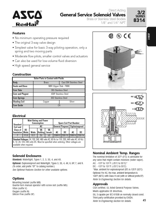
Spare Coil Part Number General Purpose Explosionproof
Class of DC
VA
VA
Insulation Watts Watts Holding Inrush AC DC AC DC
F
11.6 10.1 25
50 238610 238710 238614 238714
11.6/F 11.6/F 11.6/F 11.6/F 11.6/F 11.6/F
Specifications (Metric units)
Kv Kv
Operating Pressure Differential (bar)
Flow Flow Pipe Orifice Factor Factor
Max. AC
AC DC
200 200 200 200 200 200 200 200 200 200 200 200
200 200 200 200 200 200 200 200 200 200 200 200
200 200 200 200 200 200 200 200 200 200 200 200
Brass Body
7
6
6
5
1/4 1.2 0.04 0.05 21
21
21
17
17
17
1/4 2.4 0.13 0.17 14
14
13
10
8
6
1/4 3.2 0.22 0.17 10
10
7
6
6
5
Normally Open (Open when de-energized)
1/8 1.2 0.04 0.05 21
电动对开多叶密闭阀使用说明书
电动对开多叶密闭阀使用说明书一、概述电动对开多叶密闭阀是一种用于控制流体的阀门,其特点是采用电动机驱动,通过对开设计,能够实现快速的开启和关闭操作,并且具备良好的密封性能。
本使用说明书将详细介绍电动对开多叶密闭阀的安装、操作、维护等方面的内容,以确保用户正确使用并延长阀门的使用寿命。
二、安装1. 确保安装位置符合要求:电动对开多叶密闭阀应安装在垂直管道上,以确保正常的液体流动,并且阀门的驱动部分应易于操作和维护。
2. 进行固定和连接:使用合适的螺栓将阀门固定在管道上,并确保连接处不漏水。
3. 进行电气连接:将电动对开多叶密闭阀的电源线与电源连接,确保电气接地可靠。
三、操作1. 启动电源:将电动对开多叶密闭阀的电源线插入电源插座,确保电源供应正常。
2. 手动操作:如需手动操作阀门,可使用手动开关装置,将其置于手动状态,并按照需要旋转手动开关装置,实现阀门的开启或关闭。
3. 自动操作:如需自动操作阀门,可使用遥控器或控制面板来控制阀门的开启或关闭。
根据实际需求,可设定阀门的开启角度或开启时间等参数。
4. 监控阀门状态:在阀门操作过程中,可通过监控面板或指示灯等设备来实时了解阀门的状态,以确保阀门的正常运行。
四、维护1. 定期检查:定期检查电动对开多叶密闭阀的外观是否有损坏或腐蚀,如有发现问题应及时修复或更换零件。
2. 清洁阀门:定期清洁阀门的内部和外部,以确保阀门的正常运行和良好的密封性能。
3. 润滑保养:定期给电动对开多叶密闭阀的关键部件进行润滑保养,以减少磨损和摩擦,延长阀门的使用寿命。
4. 备用零件:建议用户准备一些常用零件作为备用,以备不时之需。
五、注意事项1. 使用环境:电动对开多叶密闭阀应在干燥、无腐蚀性气体和适宜温度的环境中使用,以避免阀门受损。
2. 防止过载:在使用过程中,应避免超过阀门的额定负载,以免损坏阀门。
3. 预防触电:在进行维护和保养时,应切断电源,并确保阀门的电气部分不受潮湿或水浸泡。
整体普通型及整体防爆型多回转阀门电动装置使用说明书

ZB5Z~40Z ZC45Z~1000Z ZB5BZ~40BZ ZC45BZ~1000BZ 整体普通型及整体防爆型多回转阀门电动装置使 用 说 明 书OPERATION INSTRUCTION MANUAL FOR INTEGRATED NORMAL TYPE AND INTEGRATED EXPLOSION-PROOF TYPE MULTI-TURNELECTRIC V ALVE ACTUATORS一、概述General Description整体普通型、整体防爆型多回转阀门电动装置由ZB5~ZB40、ZC45~250及ZB5~ZB40B、ZC45~ZC250B阀门电动装置附加控制电气元件组成,而ZC350~ZC1000BZ由ZC180~250BZ叠加减速装置组成。
本系列阀门电动装置内置控制模块,大容量接触器,可不再使用电控箱,因此具有体积小,功能全(加设了相序自动纠正及缺相保护功能,远程控制有四种方式,另加紧急关阀功能),安装接线简单(只需接入三相动力线,即可现场操作),检修方便(电气回路通过DC24V电压控制,电气部件之间采用接插件连接)等特点。
本产品性能指标达到GB/T24923-2010《普通型阀门电动装置技术条件》的规定,防爆型性能指标达到GB3836.1-2010《爆炸性环境 第1部分:设备 通用要求》、GB3836.2-2010《爆炸性环境 第2部分:由隔爆外壳“d” 保护的设备》及GB/T 24922-2010《隔爆型阀门电动装置技术条件》的规定。
Integrated normal type and integrated explosion type multi-turn electric valve actuators consist of ZB5~ZB40, ZC45~250 and ZB5B~ZB40B, ZC45B~ZC250B electric valve actuators and additional electric control elements. And ZC350~ZC1000BZ actuators are combined with ZC180~250BZ actuators and additional gear reducers. With control module and big capacity contactors built in, these series electric valve actuators need no more electric control box. And so they are small in size and of complete functions (provided with automatic correction of phase sequence, protection of phase-lacking, four modes of remote control, and the function of emergent valve shut in addition), simple in installation and wiring (once the 3-phase power supply is connected, can local operation be carried out), easy to maintain and repair (electric circuit is controlled by DC 24V voltage, electric elements are connected one another with plugs and sockets).Performance index of these products meets with the requirements of Std GB/T24923-2010 TECHNICAL SPECIFICATIONS OF NORMAL ELECTRIC V ALVE ACTUATORS and performance index of explosion-proof type actuators meets with Std GB3836.1—2010ELECTRICAL APPARATUS FOR EXPLOSIVE GAS ATMOSPHERES—PART I: GENERAL REQUIREMENTS and Std GB3836.1-2010 Explosive atmospheres-Part 1:Equipment-General requirements and Std GB3836.2-2010 Explosive atmospheres-Part 2:Equipment protection by flameproof enclosures“d”and Std GB/T 24922-2010 TECHNICAL SPECIFICATIONS OF FLAMEPROOF ELECTIRIC V ALVE ACTUATORS.二、型号表示方法Representation of TypeMeans integrated model表示防爆型,不标注表示普通型Means max. travel (revolutions)Output speed (r/min)T为推力型,I为电站型,无字母表示Connection mode: T means thrust mode,means connection mode for power station, normalOutput torque (10N·m)ZB或ZC Product type: ZB or ZC例:ZB30T-18/ 40BZ表示输出额定转矩300N·m(30kg·m)推力型,输出转速18r/ min,最大转圈数40,防爆型,整体式。
自动阀门操作规程(3篇)
第1篇一、目的为确保自动阀门在运行过程中的安全、可靠和高效,特制定本操作规程。
二、适用范围本规程适用于公司所有自动阀门的操作和维护。
三、操作前的准备1. 熟悉自动阀门的型号、规格、结构、性能和操作原理。
2. 检查阀门是否完好,包括阀体、阀盖、阀杆、阀瓣、密封垫等部件。
3. 确认阀门安装位置是否正确,管道连接是否牢固。
4. 检查阀门控制系统的电源、传感器、执行器等设备是否正常。
四、操作步骤1. 启动阀门控制系统,确保电源和传感器正常工作。
2. 根据需要调整阀门控制参数,如开度、压力、流量等。
3. 启动阀门,观察阀门启闭是否灵活、顺畅。
4. 监控阀门运行状态,如压力、流量、温度等参数是否在正常范围内。
5. 如发现异常情况,立即停止阀门运行,查找原因并处理。
五、维护保养1. 定期检查阀门及其附件,确保无损坏、磨损、变形等现象。
2. 清洁阀门内部,清除杂质、污垢等。
3. 检查密封垫、阀杆等易损部件,及时更换。
4. 定期检查阀门控制系统,确保传感器、执行器等设备正常工作。
5. 对阀门进行定期润滑,减少磨损,延长使用寿命。
六、紧急情况处理1. 阀门故障:立即停止阀门运行,查找原因并处理。
2. 系统压力异常:立即停止阀门运行,检查系统压力,必要时进行泄压。
3. 管道泄漏:立即停止阀门运行,查找泄漏原因,采取措施处理。
4. 火灾:立即停止阀门运行,启动消防系统,疏散人员。
七、注意事项1. 操作人员必须熟悉自动阀门的操作规程,确保操作正确。
2. 操作过程中,严禁擅自改变阀门控制参数。
3. 阀门运行时,严禁触摸阀门及其附件。
4. 阀门维护保养时,注意安全,防止发生意外事故。
八、培训与考核1. 对操作人员进行自动阀门操作规程的培训,确保其掌握相关知识和技能。
2. 定期对操作人员进行考核,确保其操作熟练、准确。
本规程自发布之日起实施,如遇特殊情况,可根据实际情况进行调整。
第2篇一、适用范围本规程适用于公司内部所有自动阀门的操作和管理,确保阀门在正常运行中发挥其应有的作用,防止因操作不当导致的事故发生。
阀门定位器.模块使用说明书

ZXQ系列电动阀门智能定位器/阀门操作器(电子式伺服控制器)使用说明书DOC NO:201109ZXQ2003ZXQ2004BZXQ2004ZXQ2004C目录一、概述 (2)二、主要技术指标 (2)三、 定位器面板....................................................3 四、 接线方式.........................................................5 五、 设定操作方法.................................................6 六、 错误代码列表 (9)附录:其它标定操作(出厂后如需此项操作,请在厂家指导下使用) (9)如顾客所购买的是本公司Z 型(机电一体)执行器,内部定位器无需对执行器转角标定,接线无误即可正常使用。
ZXQ 系列电动阀门智能定位器是以工业单片机为核心的智能信号采集控制系统,体积小巧,可选择安装在电动执行器的接线盒内或以DIN 导轨方式固定在外,能直接接收工业仪表或计算机等输出的4~20mA DC 信号(其它输入信号类型可在出厂前定制),与电位器反馈的电动执行器配套对各种阀门或装置进行精确定位操作,能对电动执行器的转角(或位移)进行自由标定,同时输出4~20mA DC 的执行器转角位置(或位移)反馈转换信号,可精确设定执行器转角位置的下限限位值和上限限位值,定位器采用3个按键操作,9个LED 灯可直接显示定位器模态,4位数码LED 通过按键切换显示阀位实际开度值、阀位设定开度值、定位器壳内温度,操作方便。
● 控制精度:0.1%~3.0%(通过U4参数可调)● 可接电动执行器反馈信号:电位器500Ω~10K Ω ● 可接收外部控制信号(DC ):4~20mA (1~5V 、0~10V 、开关量等出厂前定制) ● 输入阻抗:250Ω;● 通过修改U1参数可设定:①DRTA/正动作,RVSA/逆动作模态 ②输入信号中断时“中断”模态—OPEN(开)、STOP(停)、SHUT(闭) ● 可选:可控硅输出(AC ,1000V ,25A )● 输出执行器位置信号:低漂移输出4~20mA DC 对应执行器全闭至全开,信号完全与输入隔离(光电隔离),输出负载≤500Ω ● 环境温度:0~80℃,相对湿度:≤90%RH●有超温保护功能: 定位器壳内温度≥70℃时,定位器停止对执行器的开闭控制●外形尺寸:ZXQ2003→77mm(底面长)×76mm(底面宽)×51mm(高/厚);ZXQ2004→74 mm(底面长)×57mm(底面宽)×45mm(高/厚)ZXQ2004B→119mm(底面长)×76mm(底面宽)×26mm(高/厚)ZXQ2004C→62mm(底面长)×48mm(底面宽)×26mm(高/厚)●可通过按键自由标定输入信号所对应执行器的动作区间(一般标定为电动执行器全闭、全开位置)●可设定最大阀位限制值与最小阀位限制值●密码锁,防止误操作●防执行器频繁启动功能●带故障报警代码指示功能(E-0X)●按输入信号和执行器转角位置进行智能步距调整精确定位■■■1参照下图定位器接线端子和定位器外壳上的接线图连接好电动执行器和电源连线,注意连接时的极性,为减少电机干扰,应将电动执行器的电机控制线和反馈信号线分开走线;定位器的弱电信号线应尽量短些,若必须使用较长的连线时,应采用屏蔽信号线,外屏蔽与控制柜外壳妥善接地。
阀门电动装置说明书
1.概述多回转阀门电动装置,简称为Z型电装,是阀门实现开启、关闭或调节控制的驱动设备。
Z型电装适用于闸阀、截止阀、隔膜阀、柱塞阀、节流阀、水闸门等。
可用于明杆阀,也可用于暗杆阀。
本系列电装具有功能全、性能可靠、控制系统先进、体积小、重量轻、使用维护方便等特点。
可对阀门实行远控、集控和自动控制。
广泛用于电力、冶金、石油、化工、造纸、污水处理等行业。
本产品的性能符合JB/T8528-1997《普通型阀门电动装置技术条件》的规定。
隔爆型的性能符合GB3836.1-2000《爆炸性气体环境用电气设备第1部分:通用要求》,GB3836.2-2000《爆炸性气体环境用电气设备第2部分:隔爆型“d”》及JB/T8529-1997《隔爆型阀门电动装置技术条件》的规定。
多回转电动装置按防护类型分:有户外型和隔爆型;按控制方式分:有常规型、整体型和整体调节型;按连接型式分:有转矩型、电站型和推力型。
2.型号表示方法A:带现场按钮;F:带4-20mA信号输出;S:带手动减速箱输出轴最大转圈数:阿拉伯数字表示,无数字见表1输出转速:阿拉伯数字表示,单位r/min(转/分)连接型式:T表示推力型,I表示电站型,无代号为常规转矩型额定输出转矩:阿拉伯数字表示,单位kgf·mZ:整体型;TZ:整体调节型防护类型:W表示户外型;B表示隔爆型产品型式:多回转电动装置型号示例:1.DZW30I-18/50:多回转电动装置,输出转矩300N·m(30kgf·m),电站型接口,输出转速18r/min,最大转圈数50,常规户外型。
2.DZBTZ45T-24B/S:多回转电动装置,输出转矩450N·m(45kgf·m),推力型接口,输出转速24 r/min,最大转圈数120,整体调节隔爆型,带手动减速箱。
3.DZZ120-24/240:多回转电动装置,输出转矩1200N·m (120kgf·m),转矩型接口,输出转速24 r/min,最大转圈数240圈,整体型。
自动化阀门操作规程(3篇)

第1篇一、概述自动化阀门是工业生产中常用的控制元件,主要用于控制流体介质的流量、压力和方向。
为确保自动化阀门的正常运行,提高生产效率,保障人身和设备安全,特制定本操作规程。
二、操作人员要求1. 操作人员应熟悉自动化阀门的原理、结构、性能及维护保养知识。
2. 操作人员应具备一定的电工、电子、机械等方面的基本技能。
3. 操作人员应遵守本规程,严格执行操作程序。
三、操作前的准备1. 检查自动化阀门及其附件是否完好,如有损坏、变形、磨损等现象,应立即更换。
2. 检查电源、控制系统、执行机构等设备是否正常,如有异常,应立即排除。
3. 检查阀门的安装位置、方向、距离是否符合要求。
4. 检查操作人员的安全防护措施是否到位。
四、操作程序1. 启动设备前,先进行手动操作,确认阀门开关灵活、无卡阻现象。
2. 启动设备后,根据生产需求调整阀门开度,实现流量、压力、方向等控制。
3. 监控阀门运行状态,发现异常情况,立即采取措施进行调整。
4. 定期检查阀门密封性能,如有泄漏,应及时更换密封件。
5. 定期检查阀门执行机构,确保其正常工作。
6. 根据生产需求,调整阀门开度,实现流量、压力、方向等控制。
五、操作注意事项1. 操作人员应严格按照操作程序进行操作,不得擅自更改程序。
2. 操作过程中,注意观察阀门运行状态,如有异常,立即停止操作,查找原因并排除。
3. 操作过程中,严禁无关人员进入操作区域。
4. 操作人员应定期进行培训,提高操作技能和安全意识。
5. 操作人员应保持工作环境整洁,不得随意堆放杂物。
六、操作后的维护保养1. 关闭设备后,检查阀门及其附件是否完好,如有损坏,应及时更换。
2. 清洁阀门表面,保持设备整洁。
3. 检查电源、控制系统、执行机构等设备,确保其正常工作。
4. 定期检查阀门密封性能,如有泄漏,及时更换密封件。
5. 定期检查阀门执行机构,确保其正常工作。
六、附则1. 本规程适用于自动化阀门的操作、维护保养。
智能阀门定位器YT-3300系列使用说明书
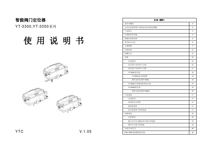
智能阀门定位器YT-3300,YT-3350系列使 用 说 明 书YTC V.1.05- 目 录(硬件)-说明书概要3安全注意事项和产品保证内容及保证期限3产品简介4主要特征和功能4铭牌内容和说明5型号标记方法6主要参数7内部结构8防爆认证9安装10注意事项10直行程产品外形尺寸图10角行程产品外形尺寸图11 YT-3300L的安装12 YT-3300L的安装例图 12利用支架安装YT-3300L12 YT-3300L无管路连接型的安装15 YT-3300R的安装16利用支架安装YT-3300R16气管连接17注意事项17使用的空压条件17接管的条件17执行机构和气管的连接17电源连接18注意事项18输入信号以及输出信号端子的连接18限位开关端子的连接19自动/手动开关20 PTM, HART选项模块的安装20- 目 录 (软件)-自动设定和基本操作方法22按钮说明22正常运行模式(RUN模式)的说明23自动设定 (AUTO CAL)23自动设定1 (AUTO 1) 24自动设定2 (AUTO 2)24自动设定HF (AUTO HF) 24手动模式(MANUAL)24参数模式 (PARAM)25死区(dEAdZONE)设定25 P 值设定(KP)25I 值设定(KI)25D 值设定(KD)25P_ 值设定(KP_)26 I_ 值设定(KI_)26 D_值设定(KD_)26 BIAS值设定26 KF值设定26手动设定模式 (HAND CAL)26手动设定模式的种类26阀门的零点和量程的设定26阀位反馈信号的零点和量程设定27按行程百分比降低阀门量程(PE TRIM)27设定反馈信号的正/反输出信号(TR_NORM/REV)28 HART通讯的正/反输出设定( HT NORM / REVS )28阀门模式(VALVE)28动作模式的变更 (ACT)28流量特性的变更 (CHAR)29用户自定义流量特性的设定 (USER SET)29正作用阀门紧密关闭功能的设定 (TSHUT OP)29反作用阀门紧密关闭功能的设定 (TSHUT CL)29分程控制 (SPLIT)30用户自定义零点信号设定(CST ZERO)30用户自定义量程信号设定(CST ENd)30角度补偿模式 (ITP OFF/ON)30查看模式(VIEW)31错误警告代码32主程序软件导航图33智 能 阀 门 定 位 器 YT-3300,YT-3350系列说明书概要感谢选用我公司产品。
多路阀使用手册
诚峰智远全自动多路阀说明书

全自动过滤阀—GA时间型(不带关闭工位)代号:CF:00(LED显示屏)北京诚峰智远科技有限公司目录一、注意事项二、产品简介三、基本说明1、控制面板功能及其意义2、阀门通电后显示屏显示3、出厂默认参数4、按键的意义5、参数查询、设定及修改6、手动功能7、显示8、保护功能9、信号输出及控制功能10、安装管路及水路试运行11、通电试运行12、控制电路功能及连接A、信号输出端口B、互锁C、泄压端口D、远程控制端口四、常见故障及其排除方法五、组件及零部件编号六、保修说明一、注意事项★确保产品安装后的正常使用,请在使用前让专业的安装或维修人员确认。
★安装时如有任何管道工程及任何电器工作都必须由专业人员完成。
★本阀门安装时需要远离强磁场,如果有变频器和水泵,变频器和水泵的连接线需要用屏蔽电缆连接。
★严禁将该阀用于不安全的或者不明水质的地方。
★过滤个过程的参数应根据工作条件的变化和出水的要求及时修正。
★使用过程中,应周期性的检测水质,以确保系统的正常运行。
★切勿将阀门靠近热源或高湿度、有腐蚀性、强磁场、强震动等环境中,亦不能将其直接暴露于室外。
★严禁将排水管和其他接头作为支撑提升或搬运系统。
★请在水温为5~50℃、水压为0.15~0.6MPa范围内使用本产品,在此范围外使用本产品所引发的故障或事故不在本公司责任及保修之列。
★如果进水压力大于0.6MPa,需在进水口端安装减压阀;进水压力低于0.15MPa 时,应在进水端加装增压泵。
★切勿让儿童接触或玩耍,不小心碰到操作键可能导致程序发生变化。
★本产品附带的电源线及电源适配器损坏时,必须更换本公司出厂的电源线及电源适配器。
二、产品概述1、主要用途适用范围主要用于水处理系统中进行过滤过程的智能化控制。
适用于家用过滤系统、泳池过滤设备、反渗透预处理系统中的过滤器等。
2、产品特点2.1 结构简单密封可靠采用高平面度、耐腐蚀的端面密封片开闭,密封可靠;集运行、反洗、正洗等全过程功能于一体。
全自动多路阀说明书(GA时间型不带关闭工位)
全自动多路阀说明书(GA时间型不带关闭工位)全自动多路阀说明书(GA时间型不带关闭工位)一、产品概述全自动多路阀(GA时间型不带关闭工位)是一种高效、可靠的控制器件,广泛用于工业自动化系统中。
该阀可实现多个工位间的流体控制,并能根据预设的时间间隔自动切换工位,满足各种生产工艺的需求。
二、产品特点1. 自动切换工位:该阀采用先进的控制技术,能够根据预设的时间间隔自动切换工位,实现工位之间的流体控制。
2. 高可靠性:该阀采用优质材料制造,结构设计合理,具有良好的密封性和耐用性,能够稳定运行并保持长期的使用寿命。
3. 简单操作:该阀配置了直观的控制界面,用户可以通过操作界面方便地进行参数设置和工位切换,操作简便,无需专业技术人员。
4. 多种配置选择:根据用户的实际需求,该阀可提供不同的配置选项,如工位数量、时间间隔设定等,以满足不同工艺流程的要求。
三、产品安装及调试1. 安装要求:(1) 在安装前,确保供电电源与产品额定电压相符,并确保电气接线正确无误。
(2) 安装阀体时,请注意阀体上的标识,确保阀体与管路连接正确。
(3) 安装完成后,对管路进行检查,确保连接牢固,无泄漏现象。
2. 参数设置:(1) 连接电源后,按下电源开关,控制界面显示正常后,进行参数设置。
(2) 通过界面上的按键,进入参数设置菜单,按照实际需求设置工位数量和切换时间间隔等参数。
(3) 设置完成后,保存参数设置并退出设置菜单。
3. 调试及使用:(1) 验证参数设置是否生效:将该阀接入相应的流体管路中,观察控制界面上的显示状态,确认程序是否按预期正常运行。
(2) 手动操作验证:通过控制界面上的手动操作按钮,手动切换工位,观察流体流向是否切换正确。
(3) 正常运行使用:在参数设置和手动操作验证正常后,可使阀正常运行,完成工位间的自动切换控制。
四、维护保养1. 定期检查:定期检查控制设备及管路连接情况,确保连接处无泄漏现象。
2. 清洁保养:定期对控制设备进行清洁,并检查连接螺丝是否松动,确保设备的正常运行。
智能阀门定位器说明书
3.5.2 阀门定位器参数设定及初始化
3.5.2.1 液晶显示器显示内容及操作键的说明 液晶显示有两行:第一行显示项目数值; 第二行显示 分项项目号和项目内容。 :功能键; :减键 :加键
3.5.2.2 定位器运行的三种状态 1.未初始化状态
定位器出厂后第一次通电应用,定位器 首先进入图3.5.2.2.1界面,此界面显示5秒, 在5秒内,按任意键即刻进入未初始化状态
说明:在进行电气连接前保 证所有的可选择模块已安 装好。
注意:在进行电气安装时, 请参见相关标准,尤其在 危险的环境中更要依据危 险
环境安装规则进行。接线务 必按接线图进行
3.3.1 两线制4—20mA连接
图3-3-1 标准两线制连接
3.3.2 三线/四线制连接
图 3-3-2 三线/四线制标准连接
3.3.3 分程连接
图3-3-3 分程控制两个定位器,分程设定范围(独立供电电源)
3.3.4 位置变送电流输出模块连线
图3-3-4.1位置变送电流输出模块连线(非危险环境)
图 3-3-4.2 位置变送电流输出模块连线(危险环境)
3.3.5 报警接口连线
图 3-3-5 报警模块连线图
3.4 气动连接
•l 由有经验的人员进行安装、维护和故障处理 •l 严格按说明书进行操作和维护 •l 使用时不可超出定位器的有关限制值 •l 遵循说明书中的注意事项
1. 智能阀门定位器简介
DLA1011E型智能阀门定位器与气动执行器结合在一起形成控制回路。 由主控制器或控制系统给定设定值W,相应地智能定位器输出压力为Y的 气体给气动执行器,从而确定阀门的开度位置X。
DLA1011E型智能阀门定位器是具有丰富功能、可通讯的新一代阀门定 位器。DLA1011E具有精巧的外观设计,模块化的内部结构,无可比拟的 性能价格比。与传统的阀门定位器相比,它的机械运动部件大大减少, 从而大大降低了故障率,提高了可靠性。
- 1、下载文档前请自行甄别文档内容的完整性,平台不提供额外的编辑、内容补充、找答案等附加服务。
- 2、"仅部分预览"的文档,不可在线预览部分如存在完整性等问题,可反馈申请退款(可完整预览的文档不适用该条件!)。
- 3、如文档侵犯您的权益,请联系客服反馈,我们会尽快为您处理(人工客服工作时间:9:00-18:30)。
全自动过滤阀
—GA时间型( 不带关闭工位)
代号: CF: 00( LED显示屏)
北京诚峰智远科技有限公司
目录
一、注意事项
二、产品简介
三、基本说明
1、控制面板功能及其意义
2、阀门通电后显示屏显示
3、出厂默认参数
4、按键的意义
5、参数查询、设定及修改
6、手动功能
7、显示
8、保护功能
9、信号输出及控制功能
10、安装管路及水路试运行
11、通电试运行
12、控制电路功能及连接
A、信号输出端口
B、互锁
C、泄压端口
D、远程控制端口
四、常见故障及其排除方法
五、组件及零部件编号
六、保修说明
一、注意事项
★确保产品安装后的正常使用, 请在使用前让专业的安装或维修人员确认。
★安装时如有任何管道工程及任何电器工作都必须由专业人员完成。
★本阀门安装时需要远离强磁场, 如果有变频器和水泵, 变频器和水泵的连接线需要用屏蔽电缆连接。
★严禁将该阀用于不安全的或者不明水质的地方。
★过滤个过程的参数应根据工作条件的变化和出水的要求及时修正。
★使用过程中, 应周期性的检测水质, 以确保系统的正常运行。
★切勿将阀门靠近热源或高湿度、有腐蚀性、强磁场、强震动等环境中, 亦不能将其直接暴露于室外。
★严禁将排水管和其它接头作为支撑提升或搬运系统。
★请在水温为5~50℃、水压为0.15~0.6MPa范围内使用本产品, 在此范围外使用本产品所引发的故障或事故不在本公司责任及保修之列。
★如果进水压力大于0.6MPa, 需在进水口端安装减压阀; 进水压力低于0.15MPa 时, 应在进水端加装增压泵。
★切勿让儿童接触或玩耍, 不小心碰到操作键可能导致程序发生变化。
★本产品附带的电源线及电源适配器损坏时, 必须更换本公司出厂的电源线及电源适配器。
二、产品概述
1、主要用途适用范围
主要用于水处理系统中进行过滤过程的智能化控制。
适用于家用过滤系统、泳池过滤设备、反渗透预处理系统中的过滤器等。
2、产品特点
2.1 结构简单密封可靠
采用高平面度、耐腐蚀的端面密封片开闭, 密封可靠; 集运行、反洗、正洗等全过程功能于一体。
2.2过滤阀工作流程一: 指m设定为1时, 按以下程序运行
2.3过滤阀工作流程二: 指m设定大于1时, 按以下程序运行
3、使用条件
诚峰阀的基本使用条件应符合下表中的要求:
项目要求
工作条件
工作压力0.15MPa~0.6MPa
进水温度5℃~50℃
工作环境环境温度5℃~50℃
相对湿度<95%( 25℃时)
适用电源AC100~240V/50~60Hz
进水水质浊度<20FTU
三、基本说明
1、控制面板功能及其意义
1.1、计量单位显示区域: 在时间型自动过滤阀上只显示天、分钟指示灯, 立方米
、立方米/小时、压力单位在时间型自动过滤阀上不会显示。
1.2、运行、设置显示区域: 工作、正洗、反洗、吸盐、注水、停止LED 灯闪烁时, 表示正在转向本工位; 本工位LED灯常亮时, 表示停留在本工位。
在时间型自动过滤阀上只显示工作、正洗、反洗、停止LED指示灯, 吸盐、注水在自动软化阀上才会显示。
2、阀门通电后显示屏显示:
2.1 LED显示板水阀开机显示后有”CF: xx”其中CF是诚峰公司代号, xx是阀型编号。
表示此阀门为时间型全自动过滤阀( 不带关闭工位)
2.2在通电60秒后不操作按键, 阀门将按照出厂默认参数设置运行
2.3通电后如果显示屏闪烁显示时钟, 如”12:12”闪烁, 表示停电时间过长, 提醒用户必须校对当前时间, 才能正常使用阀门( 见参数查询、设定及修改步骤6.1-6.2条) 。
3、出厂默认参数
序
号功能指示
出厂设
定
参数设定范
围
说明
1 运行天数03D 0~99天系统运行时间剩余天数
2 运行小时数20H 0~23小时系统运行时间剩余小时数
3 反洗10min 0~99:59
反洗的时间( 分钟) , 精确
到秒;
4 正洗10min 0~99:59
正洗的时间( 分钟) , 精确
到秒;
5
输出控制模
式01 01 01或02
01模式: 程序在结束运行时
信号开启, 到达运行时信号
关闭;
02模式: 程序在电机转动时
信号开启, 到位后信号关闭;
4.1、指示灯意义:
同时按下和两键5秒钟, 可对已锁定的键盘解锁。
4.2、亮起时, 表示键盘被锁住, 此时单独按任何一个键都将不起作用( 一分钟内不操作按键时, 亮起, 锁住键盘) , 解决办法: 同时按住和键约5秒钟, 至熄灭。
4.3、亮起时, 显示的数字表示当前时间。
4.4、指示灯意义:
4.4.1亮时, 表示查询状态, 经过按或可查询所设置的参数。
4.4.2闪烁时, 表示为设置状态, 经过按或可修改所设置的参数。
4.5、按键意义:
4.5.1工作状态下按键, 亮起, 进入查询状态, 可查询各参数值。
4.5.2查询状态下按键, 闪烁, 进入查询状态, 可查询各参数值。
4.5.3设置完毕后按键, 蜂鸣声”滴”响一声, 设置成功并返回查询状态。
4.6、按键意义:
4.6.1工作状态下按键, 可提前结束当前工作状态转入下一工作位置。
( 如: 当出水不合。