GSB-L1说明书
高速泵

www.tyjx.ne t
专家视点 EExxppeerrttVViieeww
以下 、固 体颗粒 小于 0. 1mm的 各种 液体泵也能正常运行。
4) 采用独特的叶轮流入口和 在广阔 转速及流 量范围内依 然有效 的螺距 递增的诱 导轮相匹配 ,使泵 在 高 转 速 下 仍 具有 卓 越 的 吸 入 性 能,即NPSHr 值低。
通用机械
卧式小 型高速泵 ,该系列产 品包括 P-1000型、P- 2000型、 P-3000 型三大类。 为适应 世界各地 化肥业 ( 尿 素生 产 ) 的 需 要, 19 67年 开 发 了 卧 式 超 大 功 率、 超 高 扬 程 高 速 泵 - HMP5 112 型 泵 ,功 率 最 大 为1 150k W,扬程最高为4 573m。 1984年又 开发了 HMP5112小 型化产 品 - HMP3 000 型 高 速 泵, 功 率 最 大为579kW,扬 程最高为 3 000m。 HMP 型 高 速 泵 是 由 两 个 单 级 高 速 泵 串 联 或 并 联 而 成的 , 代 表 了 当 代高速 泵的最高 水平,最高 转速达 25 000r/ mi n。除了胜德斯特兰公司, 英格索兰公司也推出了HS P-5150、 5200、7200三个系列高速泵。
表1 立式高速泵主要参数
流量 / (m3/ h)
3~100 3~60 3~100
扬程
/m 200~1 920 100~915 200-1 920
转速 / (r / mi n) 4 800~23 700 5 000~14 179 9 400~23 700
电动机功率 / kW 160 37 355
型号
GSB-W2 GSB-W3 GSB-W5
各种泵的型号的含义
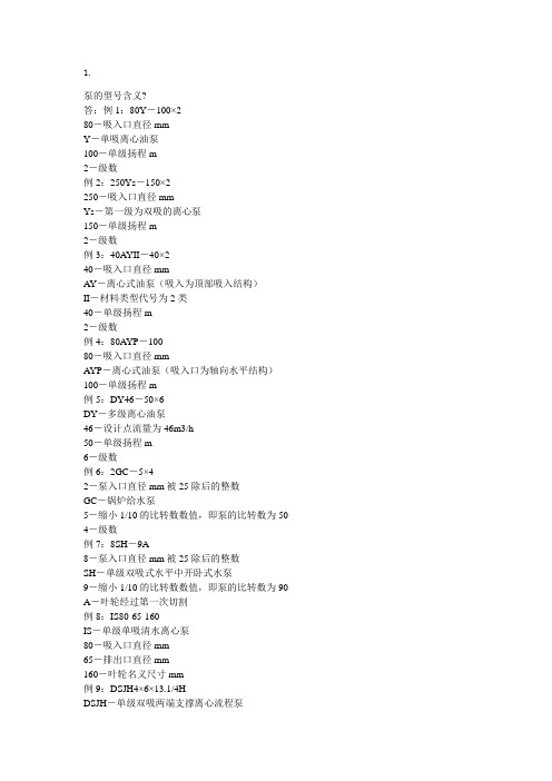
1.泵的型号含义?答:例1:80Y-100×280-吸入口直径mmY-单吸离心油泵100-单级扬程m2-级数例2:250Ys-150×2250-吸入口直径mmYs-第一级为双吸的离心泵150-单级扬程m2-级数例3:40AYII-40×240-吸入口直径mmAY-离心式油泵(吸入为顶部吸入结构)II-材料类型代号为2类40-单级扬程m2-级数例4:80AYP-10080-吸入口直径mmAYP-离心式油泵(吸入口为轴向水平结构)100-单级扬程m例5:DY46-50×6DY-多级离心油泵46-设计点流量为46m3/h50-单级扬程m6-级数例6:2GC-5×42-泵入口直径mm被25除后的整数GC-锅炉给水泵5-缩小1/10的比转数数值,即泵的比转数为50 4-级数例7:8SH-9A8-泵入口直径mm被25除后的整数SH-单级双吸式水平中开卧式水泵9-缩小1/10的比转数数值,即泵的比转数为90 A-叶轮经过第一次切割例8:IS80-65-160IS-单级单吸清水离心泵80-吸入口直径mm65-排出口直径mm160-叶轮名义尺寸mm例9:DSJH4×6×13.1/4HDSJH-单级双吸两端支撑离心流程泵4-排出口直径mm被25除后的整数6-吸入口直径mm被25除后的整数13.1/4-叶轮直径mm被25除后的整数或分数H-叶轮型式代号例10:GBL1-7.5/404G-高速B-部分流泵L-立式1-1级齿轮增速7.5-流量m3/h404-扬程m例11:GSB-L2-15/100GS-高速B-部分流泵L-立式2-2级齿轮增速15-流量m3/h100-扬程m例12:DG85-67×9DG-中压锅炉给水泵85-流量m3/h67-单级扬程m9-级数例13:SZ-2S-水环式Z-真空泵2-规格序号例14:4PW4-出口直径被25除的整数mmP-杂质泵W-污水例15:1DB-0.04/1501-缸数D-电驱动B-比例泵0.04-流量m3/h150-压力kgf/cm2例16:JZ-250/1.3JZ-中机座250-流量,升/时1.3-压力MPa例17:JT-1600/2.5JT-特大机座1600-流量,升/时2.5-压力MPa例18:JD-160/16JD-大机座160-流量升/时16-压力kgf/cm2例19:JWM-4/4.5JW-微机座M-缸体型式为隔膜式4-流量,升/时4.5-压力kgf/cm2例20:JT-2×500/16JT-特大机座2-缸数为2500-流量,升/时16-压力kgf/cm2例21:2CY-1.1/14.5-12-齿轮数C-外啮合齿轮Y-输送油1.1-流量,m3/h14.5-排出压力,kgf/cm21-第一次改型例22:3U80-103-螺杆数U-单吸螺杆泵80-主螺杆直径mm10-最大工作压力kgf/cm2例23:3G-40×4A3G-三螺杆40-主动螺杆直径mm4A-螺纹工作长度之螺距数例24:32W-7532-吸入口直径W-漩涡泵75-设计点扬程m例25:3GR-36×43G-三螺杆R-一般结构,螺杆材质36×4-主动螺杆外径×螺纹工作长度之螺距数真空泵型号及规格的表示方法根据中华人民共和国机械行业标准JB/T7673-95的规定,国产各种真空泵是由基本型号和辅助型两部分组成,两者中间为一横线。
各种泵的型号的含义

1.泵的型号含义?答:例1:80Y-100×280-吸入口直径mmY-单吸离心油泵100-单级扬程m2-级数例2:250Ys-150×2250-吸入口直径mmYs-第一级为双吸的离心泵150-单级扬程m2-级数例3:40AYII-40×240-吸入口直径mmAY-离心式油泵(吸入为顶部吸入结构)II-材料类型代号为2类40-单级扬程m2-级数例4:80AYP-10080-吸入口直径mmAYP-离心式油泵(吸入口为轴向水平结构)100-单级扬程m例5:DY46-50×6DY-多级离心油泵46-设计点流量为46m3/h50-单级扬程m例6:2GC-5×42-泵入口直径mm被25除后的整数GC-锅炉给水泵5-缩小1/10的比转数数值,即泵的比转数为50 4-级数例7:8SH-9A8-泵入口直径mm被25除后的整数SH-单级双吸式水平中开卧式水泵9-缩小1/10的比转数数值,即泵的比转数为90 A-叶轮经过第一次切割例8:IS80-65-160IS-单级单吸清水离心泵80-吸入口直径mm65-排出口直径mm160-叶轮名义尺寸mm例9:DSJH4×6×13.1/4HDSJH-单级双吸两端支撑离心流程泵4-排出口直径mm被25除后的整数6-吸入口直径mm被25除后的整数13.1/4-叶轮直径mm被25除后的整数或分数H-叶轮型式代号例10:GBL1-7.5/404G-高速B-部分流泵1-1级齿轮增速7.5-流量m3/h404-扬程m例11:GSB-L2-15/100GS-高速B-部分流泵L-立式2-2级齿轮增速15-流量m3/h100-扬程m例12:DG85-67×9DG-中压锅炉给水泵85-流量m3/h67-单级扬程m9-级数例13:SZ-2S-水环式Z-真空泵2-规格序号例14:4PW4-出口直径被25除的整数mm P-杂质泵W-污水例15:1DB-0.04/150D-电驱动B-比例泵0.04-流量m3/h150-压力kgf/cm2 例16:JZ-250/1.3 JZ-中机座250-流量,升/时 1.3-压力MPa例17:JT-1600/2.5 JT-特大机座1600-流量,升/时2.5-压力MPa例18:JD-160/16JD-大机座160-流量升/时16-压力kgf/cm2例19:JWM-4/4.5 JW-微机座M-缸体型式为隔膜式4-流量,升/时4.5-压力kgf/cm2 例20:JT-2×500/16 JT-特大机座2-缸数为2500-流量,升/时16-压力kgf/cm2例21:2CY-1.1/14.5-12-齿轮数C-外啮合齿轮Y-输送油1.1-流量,m3/h14.5-排出压力,kgf/cm2 1-第一次改型例22:3U80-103-螺杆数U-单吸螺杆泵80-主螺杆直径mm10-最大工作压力kgf/cm2 例23:3G-40×4A3G-三螺杆40-主动螺杆直径mm4A-螺纹工作长度之螺距数例24:32W-7532-吸入口直径W-漩涡泵75-设计点扬程m例25:3GR-36×43G-三螺杆R-一般结构,螺杆材质36×4-主动螺杆外径×螺纹工作长度之螺距数真空泵型号及规格的表示方法根据中华人民共和国机械行业标准JB/T7673-95的规定,国产各种真空泵是由基本型号和辅助型两部分组成,两者中间为一横线。
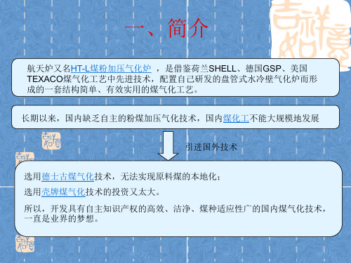
气化炉型-航天炉

电机功率 kW 5.5~22 22~55 160~315
首批 使用 年代 1988 1991 1993
四、特点
航天炉的优点 1、具有较高的热效率(可 达95%)和碳转化率(可达 99%); 2、气化炉为水冷壁结构,能承受1500℃至1700℃的高温; 3、对煤种要求低,可实现原料的本地化; 4、拥有完全自主知识产权,专利费用低,关键设备已经全 部国产化,投资少,生产成本低。据专家测算,应用航天 炉建设年处理原煤25万吨的气化工业装置,一次性投资可 比壳牌气化炉少3亿元,比德士古气化炉少5440万元;每 年的运行和维修费用比壳牌气化炉少2500万元,比德士古 气化炉少500万元。 它与壳牌、德士古等国际同类装置相比,有三大优势: 一是投资少,比同等规模投资节省三分之一; 二是工期短,比壳牌炉建设时间缩短三分之一; 三是操作程序简便,适应中国煤化工产业的实际,易于大面 积推广。
状态 固 气体 气体 气体 气体 气体
关键设备
破渣机
序号 1 2 3 4 5 6 7 8 9 10 使用单位 上海焦化厂 浩良河化肥厂 德州化肥厂 金陵化肥厂 南京大化 上海惠生 湖北双环 柳州化工 云天化 云占化 数量(台) 1 2+1 2+3 3 1+1 3 1 1 1 1 应用时间 94.12 04.4 04.10 04.10交货 05.2交货 05.3订货 04.3交货 05.3交货 05.4订货 05.5订货 备注 德士古 德士古 德士古 德士古 德士古 德士古 壳牌 壳牌 壳牌 壳牌
二、工艺介绍
HT-L粉煤气化技术工艺原理为原料煤经过磨煤、干燥后, 用N2进行加压输送,将粉煤输送到气化炉烧嘴。干煤粉 (80℃)、纯氧气(200℃)、过热蒸汽(420℃)一同 进入气化炉气化室,瞬间发生升温、挥发分裂解、燃烧及 氧化还原等物理和化学过程。生成的1400℃~1600℃的 合成气经过冷却后,出气化炉的温度为210℃~220℃, 再经过文丘里洗涤器增湿、洗涤,和洗涤塔进一步降温、 洗涤,产出温度约为204℃、粉尘含量小于10×10-6的粗 合成气。
GSB-L1型立式高速泵的运行优势及故障处理

收 稿 日期 :2017—12—28 作者 简介 :郑丽萍,女 ,工程师,从事设备管理工作 2O年 ,有着非常丰富 的工作经验 ,熟悉化工装置中各种形式 的风机、泵 、压缩机、高温及高压 设备的检修及各种故障问题 的处理。
分析 ,提 出 了合理 的 解决 办法 ,实施技 术改进 。
关 键 词 :高速 ;汽化 ;润 滑 ;密封
doi:10.3969/j.issn.1008-1267.2018.03.013
中图分类号 :TA31l
文献标 志码:A
文章编号 :1008—1267(2018)03—0033—03
为 缓 解 环保 压 力 ,河 南 省 中 原 大 化 集 团三 聚 驱 动 ,油 冷 却 器 为管 壳 式 水 冷 型 ,冷 却 水 压 力 不 大
由于 高速 泵通 过 提 高转 速 和 特殊 的 叶轮设
输 出轴 上 ,轴 向 安 装 间 距 小 ,结 构 紧 凑 。 GSB—L1 计 ,所 以 能产 生 以往 只 有 多 级 离 心 泵 或 往 复泵 才
型立 式 高 速 泵增 速 箱 采 用 强 制 润 滑 ,润 滑 系统 主 要 由下 列 零 部 件 组 成 :增 速 箱 油 池 、主 油 泵 、油 冷 却器 、油过滤器 、预润滑辅助系统及相配管件 。
解 塔 水 解 的 氨 、CO 汽 提 分 离 ,经 冷 凝 回 收 ,汽 提
它 的 高 转 速 是 通 过 优 异 的增 速 器 来 实 现 ,最
塔 C3201底 部 生 成 的精 制 水 ,可 以达 到 排 放 水 标 高 可达 34000r/min,液体 以叶轮 出 口处 的切 向速
气化炉型-航天炉教材

04年
04年 04年 04年 04年 04年
4台
4台 4台 4台 4台 4台
目前正在为下列用户:陕西神木甲醇厂、南京化学工业公司化肥厂、上海焦化总厂 生产黑水调节阀产品,其中南化公司化肥厂的阀门最高单级压降达8MPa,阀体及内件材料为 超级双相钢2507和碳化钨硬质合金。
关键设备
激冷水循环泵
型号
流量 m3/h 20 100 27 220
气化炉的核心部件是气化炉燃烧喷嘴,该喷 嘴必须具有超强的耐高温特性,这个特性要实现 起来难度较大。而与此类似,火箭上天时喷嘴所 经受的温度也很高,而且比气化炉燃烧喷嘴要经 受的温度高得多。如果把航天技术“嫁接”到煤 化工产业,那就有点像杀鸡用上宰牛刀,技术难 度上是没有问题的。 航天长征化学工程股份有限公司(简称“ 航 天工程公司”)前身为北京航天万源煤化工工程 技术有限公司,主营业务是以航天粉煤加压气化 技术为核心,专业从事煤气化技术及关键设备的 研发、工程设计、技术服务、设备成套供应及工 程总承包。航天工程公司目前拥有自主知识产权 的航天(HT-L)粉煤加压气化技术,该技术可广 泛应用于煤制合成氨、煤制甲醇、煤制烯烃、煤 制乙二醇、煤制天然气、煤制油、煤制氢、IGCC 发电等领域。
3、气化及净化 烧嘴设计同GSP,采用单烧嘴顶烧式气化,气化炉采用 TEXACO激冷工艺,气化炉升压到1MPa时,煤粉及氧、蒸汽混合以 一定的氧煤比进入气化炉,稳压1小时挂渣,炉膛内设置有8个温度 检测点,可以作为气化温度的参考点,也可以判断挂渣的状态。设计 气化温度1400-1600℃,气化压力4.0MPa。热的粗煤气和熔渣一起 在气化炉下部被激冷,也由此分离,激冷过程中,激冷水蒸发,煤气 被水蒸汽饱和,出气化炉为199℃ ,经文丘里洗涤器、洗涤塔洗涤后, 194℃、固体含量小于0.2mg/m3的合成气送去变换。 4、渣及灰水处理系统 渣及灰水处理系统的工艺流程、运行原理、控制参数都与TEXACO 工艺相同。渣经破渣机,高压变低压锁斗,排到捞渣机,进行渣水分 离,水回收处理利用;灰水经高压闪蒸、真空闪蒸后到沉降池,清水 作为激冷水回收利用 ,浆水经真空抽滤后制成滤饼。
气化炉型-航天炉

气化及合成气洗涤系统
E-1309
V-1309
氧气加热器 氧气缓冲罐
锅炉给水 中压过热蒸汽
氧气
粗合成气去火炬
粗合成气
C-1301 洗涤塔
渣及灰水处理系统
脱盐水
闪蒸气去火炬
F-1301 气化炉
V-1303 渣锁斗
V-1401 高压闪蒸罐
V-1404 真空闪蒸罐
V-1408 除氧器
冷凝液来自变换 低压饱和蒸汽 S-1402 过滤机
首批 使用 年代
1988
1991
1993
四、特点
航天炉的优点 1、具有较高的热效率(可 达95%)和碳转化率(可达99%
); 2、气化炉为水冷壁结构,能承受1500℃至1700℃的高温; 3、对煤种要求低,可实现原料的本地化; 4、拥有完全自主知识产权,专利费用低,关键设备已经全
部国产化,投资少,生产成本低。据专家测算,应用航天 炉建设年处理原煤25万吨的气化工业装置,一次性投资可 比壳牌气化炉少3亿元,比德士古气化炉少5440万元;每 年的运行和维修费用比壳牌气化炉少2500万元,比德士古 气化炉少500万元。 它与壳牌、德士古等国际同类装置相比,有三大优势: 一是投资少,比同等规模投资节省三分之一; 二是工期短,比壳牌炉建设时间缩短三分之一; 三是操作程序简便,适应中国煤化工产业的实际,易于大面 积推广。
渣及灰水处理系统的工艺流程、运行原理、控制参数都与TEXACO工 艺相同。渣经破渣机,高压变低压锁斗,排到捞渣机,进行渣水分离, 水回收处理利用;灰水经高压闪蒸、真空闪蒸后到沉降池,清水作为激 冷水回收利用 ,浆水经真空抽滤后制成滤饼。
四、关键设备
HT–L粉煤气化炉
气化压力:4MPa 气化温度:1400—1700℃
高速泵培训

二、高速泵参数
泵的数据表 泵的公用工程消耗
三、高速泵结构和控制原理
P-502A~N剖面图 P-502O~R剖面图 P-964A/B剖面图 油路PID 控制原理 机封结构图和密封冲洗方案
四、维护和检修要求
油位要求及注意事项 检修相关数据要求
到中控记录高速轴轴位移数据和泵壳振动速度; 查看机封密封水压力和流量,并做好记录,发现异常及早提出; 了解泵出口压力和电机电流,便于知晓工艺状况; 用听棒仔细听增速箱内部运行声音,主要听滚动轴承、滑动轴
承、推力轴承、机封、主油泵、齿轮壳体几处的运行声音。 检查主泵运行时,辅油泵是否在同时运行 高速泵现场照片详见下页
时保证靠背轮间距与先前一致后再进行对中,找正要 求:径向和轴向0.05mm以内;
P-502O~R主要检修数据要求有: 高速轴位移0.24±0.02mm、 径向轴承间隙0.01~0.15mm 叶轮背隙1±0.2mm、 其它要求同P-502A~N
P-9及原因分析
油压高、低报,严重联锁停车; 油温偏高 增速箱内气泡很多; 机封泄漏,分漏水、漏油和水油混合物,严
重时,漏浆料且油乳化; 轴位移高报 高速轴振动速度高 主油泵故障; 辅油泵故障 高速轴抱死,盘不动车 油冷却器泄漏
高速轴轴向窜量0.38±0.05mm 高速轴径向跳动≤0.28mm 径向轴承允许磨损量≤0.15mm 高速轴推力轴承允许磨损量≤0.025mm 节流套四氟环内径≥37.731mm予以更换
五、平时巡检注意事项
润滑油状况,检查油位、油清洁度、油温和油压记录,其中尤 其是高位和低位邮箱的油压需特别关注;
1. P-502A~N和P-617A/B 油位
烧嘴
41
7.5
2 已交/柳州化肥厂
41
55
2
42
7.5
4 已交/陕西神木
43
132
5
41
11
6 已交/金陵化肥厂
41
132
9
67
18.5
1 已交/渭河化肥厂
67
220
1
41
7.5
3 已交/山西丰喜
41
132
3
关键设备
立式高速泵
型号 GSB-L1
流量 m3/h
3~100
扬程 m
200~1920
GSB-L2 3~60 100~580
80 4.1
氮气 氧气
气体 0.67 气体 6.29
0.89 80 4.1 6.92 180 4.15
蒸汽
气体 0.24
0.69 300 5.0
液化气 气体 0.14 点火氧气 气体 0.67
20 0.3 20 0.4
关键设备
破渣机
序号 使用单位
1
上海焦化厂
2
浩良河化肥厂
3
德州化肥厂
4
金陵化肥厂
数量(台) 应用时间 备注
热风炉
1.热负荷:(200~500)×104 Kcal/h 2.热风温度:343℃ 3.热风流量:7500 m3/h
1.热负荷:(430~550)×104 Kcal/h 2.热风温度:270℃ 3.热风流量:10000 m3/h
1.热负荷:500×104 Kcal/h 2.热风温度:90~135℃ 3.热风流量:50000~135000 m3/h
1.热负荷:(100~200)×104 Kcal/h 2.热风温度:120~150℃ 3.热风流量:90100 m3/h
GSB-L2泵使用说明书讲解

则应紧急停机。其故障按“泵和齿轮箱故障处理”和“机械密封故障 处理”两节所述方法排除。 3.2 泵停机时,应先逐步关闭泵出口阀门,然后切断电源,最后关闭泵前阀 门。
4. 保养 4.1 泵运转中,如果发现参数不正常或有异常声音,应立即停机检查。 4.2 泵重新组装后,运转 24 小时应检查油位,如果油位低于规定范围,则应
温介质,泵需预冷或预热。
注意:当机械密封型式为双密封或串联密封时,应先通密封缓冲液, 后灌注泵。
1.5 调电动机转向 1.5.1 卸下电动机冷却风扇的防护罩。 1.5.2 带油压点试电动机,其风扇的旋转方向应与产品转向牌所示方向一
致,即从电动机顶部看为顺时针方向,泵叶轮转向与电动机的相反。
1.6 给油冷却器通冷却水。
冷却水流量,保证增速箱油温在 40o C ~ 70o C 之间。油冷却器的安装位置必须 低于油过滤器。更详细的信息见第二节“润滑系统”。 7. 安装 7.1 泵就位
用链式起重机从泵壳进出口法兰内管段(不允许从增速箱处起吊),吊 起带增速箱的泵总成,把泵底座水平地放在地基上,用水平仪找正上 齿轮箱体上的电机转接法兰面,水平允差 2 小格,然后用地脚螺栓锁死。 7.2 电动机及联轴器的安装 根据轴功率的大小及用户需要,电动机与增速箱之间的扭矩传递方式 有二种:叠片联轴器传扭和花键轴传扭。用户可根据泵制造厂提供的 泵总图确定传扭方式,并按下列方法进行安装。 7.2.1 叠片联轴器:复测联轴器两安装盘轴向距离 L4 (图二,其值由随机资 料外形图上查得),检查安装盘外圆和其端面 D 的跳动 ≤ 0.05mm 合格 后,用链式起重机将电机吊起放在转接法兰上,然后对号放入叠片, 锁紧螺母上涂少许锂基润滑脂,然后拧紧螺栓。
GSB 1300 Professional Instruction for use说明书

2 |English...................................................Page5Français..................................................Page9Português..............................................Página14中文.......................................................页18繁體中文..................................................頁22ไทย......................................................หน้า26Bahasa Indonesia.....................................Halaman31Tiếng Việt...............................................Trang35يبرع..................................................ةحفصلا40یسراف..................................................هحفص45 (I)1 609 92A 5E5 | (17.08.2021)Bosch Power Tools| 3(1)(2)(4)(5)(6)(7)(8)(9)(8)GSB 1300Bosch Power Tools1 609 92A 5E5 | (17.08.2021)4|1 609 92A 5E5 | (17.08.2021)Bosch Power ToolsEnglish | 5EnglishSafety InstructionsGeneral Power Tool Safety WarningsRead all safety warnings, instruc-tions, illustrations and specifica-tions provided with this power tool. Failure to follow all in-structions listed below may result in electric shock, fire and/or serious injury.Save all warnings and instructions for future reference.The term "power tool" in the warnings refers to your mains-operated (corded) power tool or battery-operated (cord-less) power tool.Work area safetyu Keep work area clean and well lit. Cluttered or dark areas invite accidents.u Do not operate power tools in explosive atmospheres,such as in the presence of flammable liquids, gases or dust. Power tools create sparks which may ignite the dust or fumes.u Keep children and bystanders away while operating a power tool. Distractions can cause you to lose control.Electrical safetyu Power tool plugs must match the outlet. Never modify the plug in any way. Do not use any adapter plugs with earthed (grounded) power tools. Unmodified plugs and matching outlets will reduce risk of electric shock.u Avoid body contact with earthed or grounded sur-faces, such as pipes, radiators, ranges and refrigerat-ors. There is an increased risk of electric shock if your body is earthed or grounded.u Do not expose power tools to rain or wet conditions. Water entering a power tool will increase the risk of elec-tric shock.u Do not abuse the cord. Never use the cord for carry-ing, pulling or unplugging the power tool. Keep cord away from heat, oil, sharp edges or moving parts. Damaged or entangled cords increase the risk of electric shock.u When operating a power tool outdoors, use an exten-sion cord suitable for outdoor use. Use of a cord suit-able for outdoor use reduces the risk of electric shock.u If operating a power tool in a damp location is un-avoidable, use a residual current device (RCD) protec-ted supply. Use of an RCD reduces the risk of electric shock.Personal safetyu Stay alert, watch what you are doing and use common sense when operating a power tool. Do not use a power tool while you are tired or under the influence of drugs, alcohol or medication. A moment of inatten-tion while operating power tools may result in serious per-sonal injury.uUse personal protective equipment. Always wear eye protection. Protective equipment such as a dust mask,non-skid safety shoes, hard hat or hearing protection used for appropriate conditions will reduce personal in-juries.uPrevent unintentional starting. Ensure the switch is in the off-position before connecting to power source and/or battery pack, picking up or carrying the tool. Carrying power tools with your finger on the switch or en-ergising power tools that have the switch on invites acci-dents.uRemove any adjusting key or wrench before turning the power tool on. A wrench or a key left attached to a rotating part of the power tool may result in personal in-jury.uDo not overreach. Keep proper footing and balance at all times. This enables better control of the power tool in unexpected situations.uDress properly. Do not wear loose clothing or jew-ellery. Keep your hair and clothing away from moving parts. Loose clothes, jewellery or long hair can be caught in moving parts.uIf devices are provided for the connection of dust ex-traction and collection facilities, ensure these are con-nected and properly used. Use of dust collection can re-duce dust-related hazards.uDo not let familiarity gained from frequent use of tools allow you to become complacent and ignore toolsafety principles. A careless action can cause severe in-jury within a fraction of a second.Power tool use and careu Do not force the power tool. Use the correct power tool for your application. The correct power tool will do the job better and safer at the rate for which it was de-signed.u Do not use the power tool if the switch does not turn it on and off. Any power tool that cannot be controlled with the switch is dangerous and must be repaired.u Disconnect the plug from the power source and/or re-move the battery pack, if detachable, from the power tool before making any adjustments, changing ac-cessories, or storing power tools. Such preventive safety measures reduce the risk of starting the power tool accidentally.u Store idle power tools out of the reach of children and do not allow persons unfamiliar with the power tool or these instructions to operate the power tool. Power tools are dangerous in the hands of untrained users.u Maintain power tools and accessories. Check for mis-alignment or binding of moving parts, breakage of parts and any other condition that may affect the power tool’s operation. If damaged, have the power tool repaired before use. Many accidents are caused by poorly maintained power tools.Bosch Power Tools1 609 92A 5E5 | (17.08.2021)6 | EnglishuKeep cutting tools sharp and clean. Properly main-tained cutting tools with sharp cutting edges are less likely to bind and are easier to control.u Use the power tool, accessories and tool bits etc. in accordance with these instructions, taking into ac-count the working conditions and the work to be per-formed. Use of the power tool for operations different from those intended could result in a hazardous situation.u Keep handles and grasping surfaces dry, clean and free from oil and grease. Slippery handles and grasping surfaces do not allow for safe handling and control of the tool in unexpected situations.Serviceu Have your power tool serviced by a qualified repair person using only identical replacement parts. This will ensure that the safety of the power tool is maintained.Safety Warnings for DrillsSafety instructions for all operationsu Wear ear protectors when impact drilling. Exposure to noise can cause hearing loss.u Use the auxiliary handle(s). Loss of control can cause personal injury.u Hold the power tool by insulated gripping surfaces,when performing an operation where the cutting ac-cessory or fasteners may contact hidden wiring or its own cord. Cutting accessory or fasteners contacting a "live" wire may make exposed metal parts of the power tool "live" and could give the operator an electric shock.Safety instructions when using long drill bitsu Never operate at higher speed than the maximum speed rating of the drill bit. At higher speeds, the bit is likely to bend if allowed to rotate freely without contact-ing the workpiece, resulting in personal injury.u Always start drilling at low speed and with the bit tip in contact with the workpiece. At higher speeds, the bit is likely to bend if allowed to rotate freely without contact-ing the workpiece, resulting in personal injury.u Apply pressure only in direct line with the bit and do not apply excessive pressure.Bits can bend causing breakage or loss of control, resulting in personal injury.Additional safety warningsu Switch the power tool off immediately if the applica-tion tool becomes blocked. Be prepared for high torque reactions which cause kickback. The applica-tion tool becomes blocked when it becomes jammed in the workpiece or when the power tool becomes over-loaded.u Hold the power tool securely. When tightening and loosening screws be prepared for temporarily high torque reactions.u Secure the workpiece. A workpiece clamped withclamping devices or in a vice is held more secure than by hand.uUse suitable detectors to determine if utility lines are hidden in the work area or call the local utility com-pany for assistance. Contact with electric lines can lead to fire and electric shock. Damaging a gas line can lead to explosion. Penetrating a water line causes property dam-age or may cause an electric shock.u Always wait until the power tool has come to a com-plete stop before placing it down. The application tool can jam and cause you to lose control of the power tool.Products sold in GB only:Your product is fitted with an BS 1363/A approved electric plug with internal fuse (ASTA approved to BS 1362).If the plug is not suitable for your socket outlets, it should be cut off and an appropriate plug fitted in its place by an au-thorised customer service agent. The replacement plug should have the same fuse rating as the original plug.The severed plug must be disposed of to avoid a possible shock hazard and should never be inserted into a mains socket elsewhere.Product Description and SpecificationsRead all the safety and general instructions.Failure to observe the safety and general in-structions may result in electric shock, fire and/or serious injury.Please observe the illustrations at the beginning of this oper-ating manual.Intended UseThe power tool is intended for impact drilling in brick, con-crete and stone, as well as for drilling in wood, metal,ceramic and plastic. Tools with electronic control and right/left rotation are also suitable for screwdriving and thread cutting.Product FeaturesThe numbering of the product features refers to the diagram1 609 92A 5E5 | (17.08.2021)Bosch Power ToolsEnglish | 7product as standard. You can find the complete selection of accessories in our accessories range.Technical Datacifications may vary at different voltages and in country-specific mod-els.Noise/Vibration InformationNoise emission values determined according to EN 62841-2-1.Typically, the A-weighted noise level of the power tool is:Sound pressure level 95 dB(A); sound power level 106 dB(A). Uncertainty K = 5 dB.Wear hearing protection!Vibration total values a h (triax vector sum) and uncertainty K determined according to EN 62841-2-1:Drilling into metal: a h = 7.5 m/s 2, K = 1.5 m/s 2Impact drilling into concrete: a h = 10.5 m/s 2, K = 1.5 m/s 2Screwdriving: a h < 2.5 m/s 2, K = 1.5 m/s 2Thread cutting: a h < 2.5 m/s 2, K = 1.5 m/s 2The vibration level and noise emission value given in these instructions have been measured in accordance with astandardised measuring procedure and may be used to com-pare power tools. They may also be used for a preliminary estimation of vibration and noise emissions.The stated vibration level and noise emission value repres-ent the main applications of the power tool. However, if the power tool is used for other applications, with different ap-plication tools or is poorly maintained, the vibration level and noise emission value may differ. This may significantlyincrease the vibration and noise emissions over the total working period.To estimate vibration and noise emissions accurately, the times when the tool is switched off or when it is running but not actually being used should also be taken into account.This may significantly reduce vibration and noise emissions over the total working period.Implement additional safety measures to protect the oper-ator from the effects of vibration, such as servicing thepower tool and application tools, keeping their hands warm,and organising workflows correctly.AssemblyuPull the plug out of the socket before carrying out any work on the power tool.Auxiliary Handle (see figure A)uDo not operate your power tool without the auxiliary handle (8).Turn the wing bolt (7) anti-clockwise and guide the auxiliary handle (8) in the required position over the drill chuck onto the spindle collar of the power tool.You can swivel the auxiliary handle (8) to any of four posi-tions in order to achieve a safe work posture that minimises fatigue.Swivel the auxiliary handle (8) to the required position. En-sure that the four grooves of the auxiliary handle are seated on the cams of the spindle collar. Turn the wing bolt (7)clockwise to retighten it.u Before carrying out any work, make sure that the wing bolt is tightened. Loss of control can cause personal in-jury.Setting the drilling depth (see figure A)You can use the depth stop (9) to set the required drilling depth X .Press the button for depth stop adjustment (6) and insert the depth stop into the auxiliary handle (8).The fluting on the depth stop (9) must face downwards.Pull the depth stop (9) far enough out that the distance between the drill bit tip and the edge of the depth stop (9)corresponds to the required drilling depth X .Changing the TooluWear protective gloves when changing tools. The drill chuck may heat up significantly when it is used for long periods.Keyed chuck (see figure B)Open the keyed chuck (1) by turning it until the tool can be inserted. Insert the tool.Insert the drill chuck key (11) into the corresponding holes of the keyed chuck (1) and clamp the tool evenly.Bosch Power Tools1 609 92A 5E5 | (17.08.2021)8 | EnglishScrewdriving tools (see figure C)You should always use a universal bit holder (13) when using screwdriver bits (12). Only use screwdriver bits that fit the screw head.For screwdriving, make sure the "drilling/impact drilling" se-lector switch (2) is always set to the "drilling" symbol.Changing the drill chuckIf your power tool does not have a drill spindle locking mech-anism, you must have the drill chuck changed by an author-Dust/Chip ExtractionDust from materials such as lead-containing coatings, some wood types, minerals and metal can be harmful to one’s health. Touching or breathing-in the dust can cause allergic reactions and/or lead to respiratory infections of the user or bystanders.Certain dust, such as oak or beech dust, is considered carci-nogenic, especially in connection with wood-treatment ad-ditives (chromate, wood preservative). Materials containing asbestos may only be worked by specialists.–Provide for good ventilation of the working place.–It is recommended to wear a P2 filter-class respirator.Observe the relevant regulations in your country for the ma-terials to be worked.u Avoid dust accumulation at the workplace. Dust can easily ignite.OperationStarting OperationuPay attention to the mains voltage. The voltage of the power source must match the voltage specified on the rating plate of the power tool. Power tools marked with 230 V can also be operated with 220 V.u Products that are only sold in AUS and NZ: Use a resid-ual current device (RCD) with a nominal residual current of 30 mA or less.Setting the rotational direction (see figure D – E)u Only operate the rotational direction switch (5) when the power tool is not in use.The rotational direction switch (5) is used to change the ro-tational direction of the power tool. However, this is not pos-sible while the on/off switch (4) is being pressed.Right rotation: To drill and to drive in screws, press the ro-tational direction switch (5) through to the left stop.Left Rotation: To loosen and unscrew screws and nuts,press the rotational direction switch (5) through to the right stop.Setting the Operating ModeDrilling and screwdrivingSet the selector switch (2) to the "drilling"symbol.Impact drillingSet the selector switch (2) to the "impact drilling" symbol.The selector switch (2) clicks into place andcan also be actuated when the motor is running.Switching on/offTo start the power tool, press and hold the on/off switch (4).Press the lock-on button (3) to lock the on/off switch (4) in this position.To switch off the power tool, release the on/off switch (4);or, if the switch is locked with the lock-on button (3), briefly press the on/off switch (4) and then release it.Adjusting the Speed/Impact RateYou can adjust the speed/impact rate of the power tool when it is on by pressing in the on/off switch (4) to varying ex-tents.Applying light pressure to the on/off switch (4) results in a low rotational speed/impact rate. Applying increasing pres-sure to the switch increases the speed/impact rate.Practical AdviceuPull the plug out of the socket before carrying out any work on the power tool.u Only apply the power tool to the screw/nut when the tool is switched off. Rotating tool inserts can slip off.After working at a low speed for an extended period, you should operate the power tool at the maximum speed for ap-proximately three minutes without load to cool it down.To drill into tiles, set the selector switch (2) to the "drilling"symbol. After drilling through the tile, set the selector switch to the "impact drilling" symbol and drill with impact.Use carbide drill bits when working with concrete, stone and masonry.When drilling into metal, only use sharpened HSS drills (HSS = high-speed steel) which are in perfect condition. The Bosch accessory range guarantees appropriate quality.Using the drill bit sharpener (accessory), you can effortlessly sharpen twist drill bits with a diameter of 2.5–10 mm.Maintenance and ServiceMaintenance and CleaninguPull the plug out of the socket before carrying out any work on the power tool.u To ensure safe and efficient operation, always keep the power tool and the ventilation slots clean.In order to avoid safety hazards, if the power supply cord needs to be replaced, this must be done by Bosch or by an1 609 92A 5E5 | (17.08.2021)Bosch Power ToolsFrançais | 9after-sales service centre that is authorised to repair Bosch power tools.After-Sales Service and Application ServiceOur after-sales service responds to your questions concern-ing maintenance and repair of your product as well as spare parts. You can find explosion drawings and information on spare parts at: The Bosch product use advice team will be happy to help you with any questions about our products and their accessor-ies.In all correspondence and spare parts orders, please always include the 10‑digit article number given on the nameplate of the product.MalaysiaRobert Bosch Sdn. Bhd.(220975-V) PT/SMY No. 8A, Jalan 13/646200 Petaling Jaya SelangorTel.: (03) 79663194Toll-Free: 1800 880188Fax: (03) 79583838E-Mail:**********************.com .myYou can find further service addresses at:/serviceaddressesDisposalThe power tool, accessories and packaging should be re-cycled in an environmentally friendly manner.Do not dispose of power tools along with household waste.FrançaisConsignes de sécuritéAvertissements de sécurité généraux pour l’outilélectriqueLire tous les avertissements de sé-curité, les instructions, les illustra-tions et les spécifications fournisavec cet outil électrique. Ne pas suivre les instructions énumérées ci-dessous peut provoquer un choc électrique,un incendie et/ou une blessure sérieuse.Conserver tous les avertissements et toutes les instruc-tions pour pouvoir s'y reporter ultérieurement.Le terme "outil électrique" dans les avertissements fait réfé-rence à votre outil électrique alimenté par le secteur (aveccordon d’alimentation) ou votre outil électrique fonctionnant sur batterie (sans cordon d’alimentation).Sécurité de la zone de travailu Conserver la zone de travail propre et bien éclairée. Les zones en désordre ou sombres sont propices aux ac-cidents.u Ne pas faire fonctionner les outils électriques en at-mosphère explosive, par exemple en présence de li-quides inflammables, de gaz ou de poussières. Les ou-tils électriques produisent des étincelles qui peuvent en-flammer les poussières ou les fumées.u Maintenir les enfants et les personnes présentes àl’écart pendant l’utilisation de l’outil électrique. Les distractions peuvent vous faire perdre le contrôle de l’ou-til.Sécurité électriqueu Il faut que les fiches de l’outil électrique soient adap-tées au socle. Ne jamais modifier la fiche de quelque façon que ce soit. Ne pas utiliser d’adaptateurs avec des outils électriques à branchement de terre. Des fiches non modifiées et des socles adaptés réduisent le risque de choc électrique.u Éviter tout contact du corps avec des surfaces reliées à la terre telles que les tuyaux, les radiateurs, les cui-sinières et les réfrigérateurs. Il existe un risque accru de choc électrique si votre corps est relié à la terre.u Ne pas exposer les outils électriques à la pluie ou à des conditions humides. La pénétration d‘eau à l’intérieur d’un outil électrique augmente le risque de choc élec-trique.u Ne pas maltraiter le cordon. Ne jamais utiliser le cor-don pour porter, tirer ou débrancher l’outil électrique.Maintenir le cordon à l’écart de la chaleur, du lubri-fiant, des arêtes vives ou des parties en mouvement. Des cordons endommagés ou emmêlés augmentent le risque de choc électrique.u Lorsqu’on utilise un outil électrique à l’extérieur, utili-ser un prolongateur adapté à l’utilisation extérieure. L’utilisation d’un cordon adapté à l’utilisation extérieure réduit le risque de choc électrique.u Si l'usage d'un outil électrique dans un emplacement humide est inévitable, utiliser une alimentation proté-gée par un dispositif à courant différentiel résiduel (RCD). L'usage d'un RCD réduit le risque de choc élec-trique.Sécurité des personnesu Rester vigilant, regarder ce que vous êtes en train de faire et faire preuve de bon sens dans votre utilisation de l’outil électrique. Ne pas utiliser un outil électrique lorsque vous êtes fatigué ou sous l’emprise dedrogues, de l’alcool ou de médicaments. Un moment d’inattention en cours d’utilisation d’un outil électrique peut entraîner des blessures graves.u Utiliser un équipement de protection individuelle.Toujours porter une protection pour les yeux. LesBosch Power Tools1 609 92A 5E5 | (17.08.2021)10 | Françaiséquipements de protection individuelle tels que lesmasques contre les poussières, les chaussures de sécuri-té antidérapantes, les casques ou les protections audi-tives utilisés pour les conditions appropriées réduisent les blessures.uÉviter tout démarrage intempestif. S’assurer que l’in-terrupteur est en position arrêt avant de brancher l’outil au secteur et/ou au bloc de batteries, de le ra-masser ou de le porter. Porter les outils électriques en ayant le doigt sur l’interrupteur ou brancher des outils électriques dont l’interrupteur est en position marche est source d’accidents.uRetirer toute clé de réglage avant de mettre l’outil électrique en marche. Une clé laissée fixée sur une par-tie tournante de l’outil électrique peut donner lieu à des blessures.uNe pas se précipiter. Garder une position et un équi-libre adaptés à tout moment. Cela permet un meilleur contrôle de l’outil électrique dans des situations inatten-dues.uS’habiller de manière adaptée. Ne pas porter de vête-ments amples ou de bijoux. Garder les cheveux et les vêtements à distance des parties en mouvement. Des vêtements amples, des bijoux ou les cheveux longs peuvent être pris dans des parties en mouvement.uSi des dispositifs sont fournis pour le raccordement d’équipements pour l’extraction et la récupération des poussières, s’assurer qu’ils sont connectés et correc-tement utilisés. Utiliser des collecteurs de poussière peut réduire les risques dus aux poussières.uRester vigilant et ne pas négliger les principes de sé-curité de l'outil sous prétexte que vous avez l'habitude de l'utiliser. Une fraction de seconde d'inattention peut provoquer une blessure grave.Utilisation et entretien de l’outil électriqueu Ne pas forcer l’outil électrique. Utiliser l’outil élec-trique adapté à votre application. L’outil électrique adapté réalise mieux le travail et de manière plus sûre au régime pour lequel il a été construit.u Ne pas utiliser l’outil électrique si l’interrupteur ne permet pas de passer de l’état de marche à arrêt et in-versement. Tout outil électrique qui ne peut pas être commandé par l’interrupteur est dangereux et il faut le ré-parer.u Débrancher la fiche de la source d’alimentation et/ou enlever le bloc de batteries, s'il est amovible, avant tout réglage, changement d’accessoires ou avant de ranger l’outil électrique. De telles mesures de sécuritépréventives réduisent le risque de démarrage accidentel de l’outil électrique.u Conserver les outils électriques à l’arrêt hors de la portée des enfants et ne pas permettre à des per-sonnes ne connaissant pas l’outil électrique ou les pré-sentes instructions de le faire fonctionner. Les outils électriques sont dangereux entre les mains d’utilisateurs novices.uObserver la maintenance des outils électriques et des accessoires. Vérifier qu’il n’y a pas de mauvais aligne-ment ou de blocage des parties mobiles, des pièces cassées ou toute autre condition pouvant affecter le fonctionnement de l’outil électrique. En cas de dom-mages, faire réparer l’outil électrique avant de l’utili-ser. De nombreux accidents sont dus à des outils élec-triques mal entretenus.u Garder affûtés et propres les outils permettant de couper. Des outils destinés à couper correctement en-tretenus avec des pièces coupantes tranchantes sont moins susceptibles de bloquer et sont plus faciles àcontrôler.u Utiliser l’outil électrique, les accessoires et les lames etc., conformément à ces instructions, en tenant compte des conditions de travail et du travail à réali-ser. L’utilisation de l’outil électrique pour des opérations différentes de celles prévues peut donner lieu à des situa-tions dangereuses.u Il faut que les poignées et les surfaces de préhension restent sèches, propres et dépourvues d'huiles et de graisses. Des poignées et des surfaces de préhension glissantes rendent impossibles la manipulation et le contrôle en toute sécurité de l'outil dans les situations in-attendues.Maintenance et entretienu Faire entretenir l’outil électrique par un réparateur qualifié utilisant uniquement des pièces de rechange identiques. Cela assure le maintien de la sécurité de l’ou-til électrique.Avertissements de sécurité pour la perceuseInstructions de sécurité pour toutes les opérationsu Porter des protecteurs d’oreille lors de l’utilisation de la perceuse à percussion.Porter des protecteursd’oreille lors de l’utilisation de la perceuse à percussion.u Utiliser la ou les poignées auxiliaires. La perte de contrôle peut provoquer des blessures.u Tenir l'outil électrique par les surfaces de préhension isolées, au cours des opérations pendant lesquelles l’accessoire de coupe ou les fixations peut être en contact avec un câblage caché ou avec son propre cor-don. Un accessoire de coupe ou les fixations en contact avec un fil "sous tension" peut "mettre sous tension" les parties métalliques exposées de l'outil électrique et pro-voquer un choc électrique chez l'opérateur.Instructions de sécurité pour l’utilisation de forets longs u Ne jamais utiliser à une vitesse supérieure à la vitesse assignée maximale du foret. À des vitesses supérieures,le foret est susceptible de se plier s’il peut tourner libre-ment sans être en contact avec la pièce à usiner, ce qui provoque des blessures.u Toujours commencer à percer à faible vitesse et en mettant l’embout du foret en contact avec la pièce àusiner. À des vitesses supérieures, le foret est suscep-tible de se plier s’il peut tourner librement sans être en1 609 92A 5E5 | (17.08.2021)Bosch Power Tools。
立式高速泵GSB--L1型

• 预润滑系统由外设润滑油泵、单向阀及管线组成。外设 润滑油泵有手动型和电动型两种。其作用是在起动主电 机前,给增速箱内的轴承和齿轮进行预润滑,从而避免 在起动时可能引起的轴承及轴组件损坏。起动主电机前, 操纵手动油泵手柄上下运动或起动电动油泵,若油压不 低于0.14MPa⋅ G ,就可起动主电机,主电机起动后,才 可停止操纵手动油泵或关闭电动油泵。
• 主油泵为定排量摆线齿轮型油泵,由增速箱输入轴直接 驱动。
• 油冷却器为管壳式水冷型,冷却水压力不大于1MPa⋅G , 冷却水流量参见随机资料。通过安装在冷却水排出管线 上的手阀调节冷却水流量,保证增速箱油温40℃—70℃ 之间。 大约在泵起动运行 1 小时后, 油温就可稳定。
• 注意,为防止在润滑油油路上存在气囊,油冷却器的安 装位置必须低于油过滤器。
• 1.2 将转接法兰与上箱体(图一)的连接螺栓卸下, 使用电动机壳体上的吊 环螺栓,用链式起重机将电动机和转接法兰一起吊下。然后取出花键轴。 对于叠片联轴器,应卸下叠片螺栓,才能起吊电机。
• 1.3 拧下密封体与泵壳联接螺栓的 20 M 螺母(图四), 利用中箱体上的 16 M 吊环螺栓,用链式起重机将增速箱连同叶轮和诱导轮一并吊起,翻转增速 箱使诱导轮呈向上状态放置。
叶轮
泵体 诱导轮 泵壳组件
加氢P-102AB 剖面图
二、润滑系统
• GSB-L1 型立式高速泵增速箱润滑系统主要 由下列零部件组成:增速箱油池、主油泵、 油冷却器、油过滤器、预润滑辅助系统及 相配管件。润滑油流程见下图。
内 部 油 路
• 增速箱使用L-HM32#抗磨液压油,油池的油量约为8升 (不包括辅助管线和油冷却器内存油量),油位应该保持 在油标视镜的黑圈内。油位过高,会产生大量泡沫及过 热,油位过低,会使供油量不足。
南洋电工 GSB-1A型 16锭高速编织机使用说明书
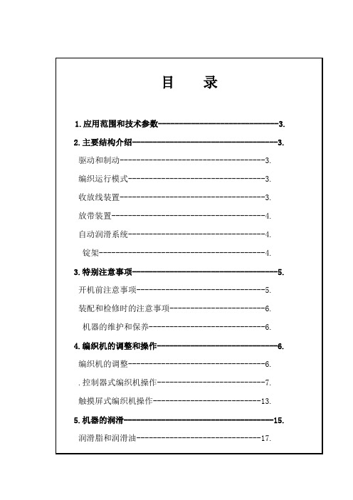
1.应用范围和技术参数GSB-1A型高速编织机主要适用于电缆行业以软金属丝,棉和塑料线作电缆护套的编织,本机也适用于绳和软线的制造。
技术参数:编织方式2迭2编织方向垂直锭数16(8上锭,8下锭)线锭尺寸752270内宽或802280内宽线锭转速50—150转/分无节调速编织节距调节范围—32.5mm或—65mm最大编织外径14mm(纵包为8mm)最大生产速度580 m/h外形尺寸120013902350mm(长宽高)2.主要结构介绍驱动和制动本机由一台变频三相电机(或,1400转/分)通过同步带带动传动轴驱动。
该传动轴再由一双联锥齿轮分别带动转盘和齿圈旋转,同时中心齿轮通过另一组锥齿轮以及节距齿轮蜗轮蜗杆驱动牵引盘运转。
收线和排线工作由一台齿轮电机(200W,36转/分)通过驱动链驱动。
机器的制动是通过在主电机变频控制器上的制动断路装置来实现的,一旦遇到线束折断、绕完或按停车按钮机器会在秒内停止转动。
编织运行模式编织机的八只下锭和相应的摆杆均固定在转盘边上,下锭编织线通过摆杆的周期上下摆动导向编织点,摆杆的摆动是通过滑块在槽圈凹槽内的滑动来实现的。
八只上锭则由齿圈、尼龙齿轮、滑动齿条驱动,在开有八个槽口的转盘导轨上绕机器中心滑动,上锭编织线直接引向编织点。
借助摆杆的摆动,下锭编织线摆出或摆进转盘导轨槽口,同时上锭正好走过下锭编织线的下面或上面,有规律的重复这一过程,由此形成22的编织层。
将编织后的电缆线在牵引盘上绕四圈,由牵引轮转动拉出电缆编织层。
按附表选取节距齿轮,即能得到不同的编织节距。
收放线装置工作台下部的收放线装置可放置最大外径为800mm的电缆盘。
电缆盘由两端装有轴承的传动轴支承,通过横挡提供的斜面安置在横挡的适当位置上转动。
收线电缆盘由齿轮电机通过一对齿轮由一个可调式摩擦离合器传动,使线盘随卷绕外径的增大(或缩小)时,保证编织的线速度保持不变。
编织后的电缆的排线由光杆排线器进行,其节距无级可调。
聚丙烯装置设备操作规程

目录1高速泵操作规程 (4)1.1高速泵结构及工作原理 (4)1.2高速泵技术参数 (5)1.3高速泵润滑系统 (5)1.4高速泵日常操作、检查、维护要求 (6)1.5高速泵故障判断以及处理方法 (7)1.6高速泵设备操作 (9)2循环氢压缩机操作规程 (11)2.1循环氢压缩机结构及工作原理 (11)2.2循环氢压缩机技术参数 (13)2.3循环氢压缩机日常操作、检查、维护要求 (13)2.4循环氢压缩机故障判断以及处理方法 (14)2.5循环氢压缩机设备操作 (16)3第一反应器循环风机操作规程 (20)3.1第一反应器循环风机结构原理 (20)3.2第一反应器循环风机技术参数 (21)3.3第一反应器循环风机润滑系统 (21)3.4第一反应器循环风机日常操作、检查、维护要求 (22)3.5第一反应器循环风机故障判断以及处理方法 (23)3.6第一反应器循环风机设备操作 (24)4冷冻机组操作规程 (27)4.1冷冻机组结构及工作原理 (27)4.2冷冻机组技术参数 (29)4.3冷冻机组开机前的准备 (29)4.4充入制冷剂 (31)4.5冷冻机组设备操作 (31)4.6冷冻机组故障及其消除办法 (34)5丙烯气压缩机操作规程 (36)5.1丙烯气压缩机结构及工作原理 (36)5.2丙烯气压缩机技术参数 (43)5.3丙烯气压缩机运动机构润滑系统 (43)5.4丙烯气压缩机辅机 (44)5.5丙烯气压缩机冷却水系统 (45)5.6丙烯气压缩机气管路系统 (45)5.7丙烯气压缩机仪表及自动监护系统 (46)5.8丙烯气压缩机气量调节管路 (46)5.9丙烯气压缩机运转试验 (47)5.10丙烯气压缩机空负荷试运转 (52)5.11丙烯气压缩机磨合活塞 (55)5.12丙烯气压缩机氮气负荷试运转 (57)5.13丙烯气压缩机工艺性运转试验 (60)5.14丙烯气压缩机紧急停机 (63)5.15丙烯气压缩机日常维护、常见故障及解决方法 (63)5.16丙烯气压缩机常见故障及解决方法 (64)6再生氮气循环风机操作规程 (71)6.1再生氮气循环风机结构及工作原理 (71)6.2再生氮气循环风机技术参数 (73)6.3日常操作、检查、维护要求 (73)6.4再生氮气循环风机故障判断以及处理方法 (75)6.5再生氮气循环风机操作 (76)7干燥器循环氮气风机操作规程 (78)7.1干燥器循环氮气风机结构及工作原理 (78)7.2干燥器循环氮气风机技术参数 (80)7.3日常操作、检查、维护要求 (80)7.4再生氮气循环风机故障判断以及处理方法 (82)7.5再生氮气循环风机操作 (83)1高速泵操作规程1.1高速泵结构及工作原理高速泵是离心泵的一种,通过增加增速器,转速得到提高。
高速泵使用说明书

果有损坏,应立即通知承运人和泵制造厂,但不要自行分解泵。 2.保护堵盖、 堵塞、堵帽等装在原来位置上,然后连同包装箱一起放在清洁、干燥、不受 潮、不沾灰、且距热源和电源大于1m 的地方。电动机的保管参见电动机安装 使用说明书。如保管期超过 6 个月,请与泵制造厂联系。 3. 长期保管
四. 分解与再装
参考随机资料、外形安装图和剖面图,按照下列步骤对泵进行分解与再 装(泵内部结构如图四所示)。 1. 分解 1.1 切断电动机电源,关闭泵进、出口阀门及机械密封辅助管线阀门。将泵 腔内液体和齿轮箱油泄出,再拆下预润滑系统等油路附件及机械密封辅助管 线。 1.2 将转接法兰与上箱体(图一)的连接螺栓卸下,使用电动机壳体上的吊环 螺栓,用链式起重机将电动机和转接法兰一起吊下。然后取出花键轴。对于 叠片联轴器,应卸下叠片螺栓,才能起吊电机。 1.3 拧下密封体与泵壳联接螺栓的 M 20 螺母(图四),利用中箱体上的 M16 吊 环螺栓,用链式起重机将增速箱连同叶轮和诱导轮一并吊起,翻转增速箱使 诱导轮呈向上状态放置。 1.4 打直诱导轮锁紧垫的凸耳,分解下诱导轮(注意是左螺纹),接着可卸下 叶轮和键,取下泵盖后,即可分解下介质密封动环和静环组件,拧下密封体 与下箱体的连接螺栓,可取下密封体和耐油橡胶石棉垫,从密封体上分解下 节流套或介质密封(对双密封、串联密封结构),分解下轴套组件后,可分解 油机械密封静环组件,接着可取出油密封动环。 1.5 翻转并架起增速箱(使伸出的高速轴部分向下悬空),卸下增速箱大法兰 连接螺栓和定位螺栓后,首先可分解上箱体,接着可取下输入轴组件、油泵 弹簧和油泵,取下中箱体后可分解下中间轴组件和高速轴组件,然后可从中、 下箱体上分解高速滑动轴承,最后从滚动轴承孔取下喷油嘴。注意:分解上 箱体前,先取下排气加油器。 1.6 使用泵随带的 M 8吊环螺栓,可取出扩压器。 2. 再装 2.1 要在清洁的环境进行装配。 2.2 所有参加装配的零部件(包括继续使用件和换上的备件)都应仔细清洗干 净。金属件用汽油清洗,非金属件用工业酒精清洗。 2.3 按分解的反顺序进行装配,即先装增速箱,再装密封体和机械密封,然 后装好叶轮和诱导轮,将扩压器装入泵壳后,可将密封体与泵壳组件连接螺 栓拧紧,插入花键轴后,即可吊装带转接法兰的电动机,并装好与上箱体的 连接螺栓。对于金属叠片联轴器则按“一.7.2.2”规定安装,最后装好预润滑 系统等油路附件及机械密封辅助管线。在吊装过程中,要严防碰伤诱导轮, 为此在密封体与泵壳对接时,要用导向销找正(见图一)。 2.4 有拧紧力矩要求的螺纹联接,按表二规定。
立式高速泵故障分析及应对措施

立式高速泵故障分析及应对措施摘要:立式高速泵主要由多个部件组成,不仅包括泵体和轴承,还包括变速箱和辅助油泵。
在离心力的作用下,液体可以从中心抛向外缘,也可以获得一定的动力离开外缘进入蜗壳。
在巢壳中,由于流动通道的逐渐膨胀,液体减慢速度,将其转化为部分势能和静压能。
通过高压排放管道输送至所需位置。
同时,当液体从叶轮的中心流到外缘时,可以在中心产生真空环境。
此时,管道内部的压力大于叶轮的中心,液体会压入叶轮,形成一定的循环。
立式高速泵由于其诸多优点,已经渗透到化工和石油行业,并得到了合理的应用。
然而,在立式高速泵的运行中,有时也会出现故障问题。
因此,应采取有效的维修措施,解决其故障问题,使其立式高速泵处于良好的运行状态。
关键词:立式高速泵;过错维修简介:本文主要对立式高速泵的故障分析与维修进行了深入研究。
首先,阐述了立式高速泵的故障,如电机和齿轮箱振动大、润滑系统维护力度不够、密封冲洗油系统故障等。
然后,提出了几种切实可行的对策,主要包括设备运行维护、机械密封改造、干气密封的应用,以及齿轮箱润滑系统。
此外,它可以更好地解决立式高速泵的故障问题,促进立式高速泵更好地运行,提高其运行水平。
一、高速泵的工作原理立式高速泵采用电动机驱动齿轮箱内部的传动机构,以提高泵体和叶轮的工作速比,促进泵更好地运行,使其保持良好的工作状态。
其工作原理与离心泵基本相同,不同之处在于增加了一个变速箱结构。
一般来说,变速箱结构主要由一级齿轮增速结构组成。
齿轮箱使高速泵叶轮能够达到更高的速度,这在一定程度上提高了输送介质沿叶轮外缘的线速度。
二、立式高速泵故障的分析(一)润滑系统和密封冲洗油系统故障齿轮箱的内部润滑系统主要利用循环运行时安装在低速轴上的固定排量摆线针轮。
润滑油通过外部过滤器和冷却器强制润滑各种润滑部件。
此外,为了保证摆线油泵的正常工作,必须转动低速轴。
因此,在正式启动高速泵的早期阶段,对于电动辅助油泵,应正式启动,以确保变速箱中的润滑系统压力达到一定值,并进一步预润滑内部的各个润滑点。
高速泵的操作规程
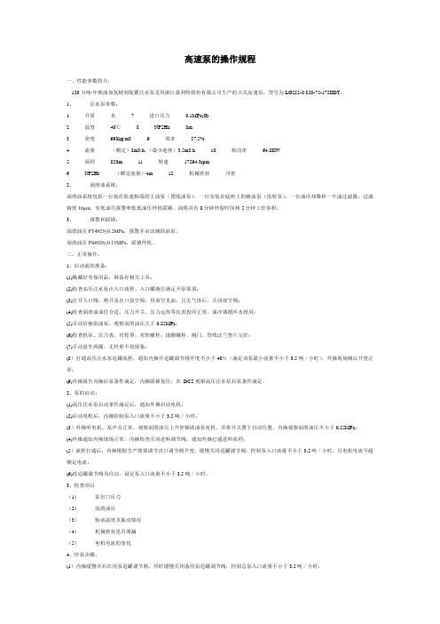
高速泵的操作规程一、性能参数简介:120万吨/年柴油加氢精制装置注水泵采用浙江嘉利特股份有限公司生产的立式高速泵,型号为LG222-8/820-75-172IIDT。
1、注水泵参数:1 介质水7 进口压力0.1MPa(G)2 温度40℃8 NPSHa 8m3 密度998kg/m3 9 效率27.5%4 流量(额定)8m3/h;(最少连续)3.5m3/h 10 轴功率64.8KW5 扬程820m 11 转速17294.3rpm6 NPSHr (额定流量)4m 12 机械密封川密2、润滑油系统:润滑油系统包括一台装在低速轴端的主油泵(摆线油泵),一台安装在底座上的辅油泵(齿轮泵),一台油冷却器和一个油过滤器,过滤精度10μm,有低油压报警和低低油压停机联锁。
油箱具有8分钟停留时间和5分钟工作容积。
3、报警和联锁:润滑油压PT4925≤0.2MPa,报警并启动辅助油泵。
润滑油压PS4926≤0.15MPa,联锁停机。
二、正常操作:1、启动前的准备:(1)佩戴好劳保用品,准备好相关工具;(2)检查高压注水泵出入口流程、入口罐液位满足开泵要求;(3)打开入口阀,稍开泵出口放空阀,待放空见油,且无气体后,关闭放空阀;(4)检查润滑油油位合适,压力开关、压力远传等仪表投用正常,油冷器循环水投用;(5)手动启辅助油泵,观察润滑油压大于0.25MPa;(6)检查机泵、压力表、对轮罩、对轮螺栓、地脚螺栓、阀门、管线法兰垫片完好;(7)手动盘车两圈,无轻重不均现象;(8)打通高压注水泵返罐流程,通知内操开返罐调节阀开度不小于40%(满足该泵最小流量不小于3.5吨/小时),外操现场确认开度正常;(9)外操报告内操启泵条件满足,内操联锁复位,在DCS观察高压注水泵启泵条件满足。
2、泵的启动:(1)高压注水泵启动条件满足后,通知外操启动电机;(2)启动电机后,内操控制泵入口流量不小于3.5吨/小时;(3)外操听电机、泵声音正常,观察润滑油压上升停辅助油泵电机,并将开关置于自动位置,内操观察润滑油压不小于0.25MPa;(4)外操通知内操现场正常,内操检查关闭进料调节阀,通知外操打通进料流程;(5)流程打通后,内操根据生产需要调节出口调节阀开度,缓慢关闭返罐调节阀,控制泵入口流量不小于3.5吨/小时,且电机电流不超额定电流;(6)改返罐调节阀为自动,设定泵入口流量不小于3.5吨/小时。
动设备管理规定(新修订)

辽河石化公司动设备管理规定1 范围规定了中国石油辽河石化公司动设备的专业管理职责、管理内容与要求。
本规定适用于中国石油辽河石化公司的动设备管理。
2 引用标准2.1 《辽河石化公司设备设施管理程序》2.2 《中国石油天然气股份有限公司炼油化工企业设备管理规定》2.3 《质量健康安全环境管理手册》2.4 《炼油化工建设项目竣工验收手册(2008版)》3 术语及定义3.1 四懂、三会·懂性能、懂原理、懂结构、懂用途;会操作使用、会维护保养、会排除故障。
3.2 润滑“五定”·定时、定点、定量、定质、定人。
3.3 三级过滤从领油桶到岗位储油桶、从岗位储油桶到油壶、从油壶到加油点按规定过滤。
3.4 十字作业法·清洁、润滑、紧固、调整、防腐。
3.5 五字操作法·听、摸、查、比、看。
3.6 四不超·不超温、不超压、不超负荷、不超速。
3.7 三对照、一试装·国产件与图纸对照、图纸与进口件对照、国产件与进口件对照,试用前试装配。
3.8 设备的A.B.C.类3.8.1根据设备在生产过程中所起的作用、维修的难易程度、设备参数、设备原值等因素综合考虑,将设备分为A、B、C类三类。
4 职责4.1 机动设备处按照公司《动设备分类原则》划分动设备类别,组织做好动设备特护管理、润滑管理、盘车管理、检维修管理、备品配件管理工作,并对公司各单位进行业务指导及检查考核。
4.2 公司各单位按《设备设施管理程序》中规定的职责,结合本规定各支持性管理办法中明确的具体分工相应开展工作。
5 管理内容及要求5.1 动设备的分类管理5.1.1 辽河石化公司对动设备施行分类管理。
动设备分类原则依据表一标准评分,总分120分以上为公司A类设备,•80分至120分为公司B类设备,其余为C 类设备。
分类标准见表一。
表一转动设备评分标准5.1.2 为降低全公司关键动设备故障率,提高生产运行可靠度,以期实现装置长周期运行,在分析总结以往转动设备故障的基础上,对下列动设备实行强制检修。
LG BBL1 美肤导入仪 使用说明书

Model nameBBL1Galvanic Ion BoosterCLEANSINGBOOSTMODECLEANSINGBOOSTMODEeCLEANSINGBOOSTMODECLEANSINGBOOSTMODE1905_Rev01MBM67016511Precautions for usey Depending on individual skin condition, the device may cause a variety of skin irritations.If such irritation persists, please reduce the number of uses. y In the following cases, it is recommended to use the device after consultation with a specialist.-Skin Allergies, acne, dermatitis, undergoing skin treatment orcosmetic surgery or hair loss surgery-Wearing a cardiac pacemaker, implant device or a metal prostheticy Device to be used as a facial treatments only, it is not recommended for use on body. y Recommend product use is once a day by mode. Using more than twice a day may cause a burning sensation on skin. y Before using the device, if you are currently undergoingdermatology related treatment or have skin problems, consult your dermatologist and then use it. y Device use not recommended for pregnant, menstruating or lactating women. (Unstable hormonal balance may cause temporary skin issues.)y Do not use the device for purposes other than those set out in this guide. y Please pay attention to using cosmetics that contain the following ingredients as it may reduce the effect: denatured alcohol, sunscreen, retinol, oilChargingCLEANSING BOOSTEANS IN N GBOO MODEMode Selection(CLEANSING / BOOST)Press the MODE button for a shortwhile.(CLEANSING BOOST)y Cleansing Mode (CLEANSING): To make your skin cleaner, it is effective to use this mode before using Absorption Promotion Mode. Main functions: Warm, Ion (+)CLEANSING BOOSTEANS IN N GMODECLEANSING BOOSTMODE EANS IN N GB ODEey Absorption Promotion Mode (BOOST): The complex function of the mode helps the penetration of active substances contained in cosmetics. Main functions : Warm, Ion (-), Ultrasonic wave。
- 1、下载文档前请自行甄别文档内容的完整性,平台不提供额外的编辑、内容补充、找答案等附加服务。
- 2、"仅部分预览"的文档,不可在线预览部分如存在完整性等问题,可反馈申请退款(可完整预览的文档不适用该条件!)。
- 3、如文档侵犯您的权益,请联系客服反馈,我们会尽快为您处理(人工客服工作时间:9:00-18:30)。
GSB-L1 型立式高速泵使用说明书
前言
本使用说明书提供了 GSB − L1型立式高速泵的安装、使用、故障处理、 维护保养及备品备件方面的信息。
GSB − L1型立式高速泵为单级单吸部分流式离心泵,由电动机、齿轮增 速箱(二级增速)、泵及其附件组成。性能范围:流量不超过100m3 h ,扬程 不超过1900m ,转速 4,800r / min ~ 23,700r / min ,功率不超过150kW ,吸入压力 不超过 7MPa ,工作压力不超过15MPa ,介质温度 −130o C ~ 340o C 。泵外形如 图一所示。当电机功率大于132kW 或电机重量大于1400kg 时,需要使用电机 支架,其结构关系及安装要求详见主泵随机资料。本说明书侧重于高速泵 本身的安装、使用、保养和检修。
1. 检查 泵到货后,应立即进行外观检查,看有没有在运输过程中造成损坏。
如果有损坏,应立即通知承运人和泵制造厂,但不要自行分解泵。
2. 保管 要是泵不立即安装,则应在原包装箱内放好,出厂时安装的保护堵盖、
堵塞、堵帽等装在原来位置上,然后连同包装箱一起放在清洁、干燥、不 受潮、不沾灰、且距热源和电源大于1m 的地方。电动机的保管参见电动机 安装使用说明书。如保管期超过 6 个月,请与泵制造厂联系。
主油泵为定排量摆线齿轮型油泵,由增速箱输入轴直接驱动。 油冷却器为管壳式水冷型,冷却水压力不大于1MPa ⋅G ,冷却水流量参 见随机资料。通过安装在冷却水排出管线上的手阀调节冷却水流量,保证 增速箱油温在 40o C ~ 70o C 之间。大约在泵起动运行 1 小时后,油温就可稳定。 注意,为防止在润滑油油路上存在气囊,油冷却器的安装位置必须低于油 过滤器。 预润滑系统由外设润滑油泵、单向阀及管线组成。外设润滑油泵有手 动型和电动型两种。其作用是在起动主电机前,给增速箱内的轴承和齿轮 进行预润滑,从而避免在起动时可能引起的轴承及轴组件损坏。起动主电 机前,操纵手动油泵手柄上下运动或起动电动油泵,若油压不低于 0.1MPa ⋅G ,就可起动主电机,主电机起动后,才可停止操纵手动油泵或关 闭电动油泵。 油过滤器为纸质型,过滤精度为 5μm 。每 6 个月应停机更换润滑油和油 过滤器。 根据轴承结构及使用的润滑油情况,正常运转时,增速箱油压应保持 在 0.2 ~ 0.6MPa ⋅ G ,增速箱绝对不能在油压低于 0.14MPa ⋅ G 时工作。用户可根 据需要安装润滑油油压报警开关。
7.2.4 电源接线:按电动机安装使用说明书进行。 7.3 管线连接 7.3.1 泵进出口管线的连接必须使管线法兰与泵壳法兰对正。 7.3.2 根据随机资料,连接密封体上孔口 1-7 对应的管线。 7.3.3 密封体上的孔口1(见图一)在任何情况下都是打开的,或直接排放到
大气中,或引到安全的地方(背压不大于 0.04MPa ⋅ G )。
允许使用温度 0o C ~ 80o C 最适宜温度 40o C ~ 70o C
1.2.3 卸下图一所示排气加油器的罩帽接嘴,由弯管加油,同时打开弯管下 方的堵塞排气。加油量约 8 升(不包括辅助管线和油冷却器内的存油 量),直到油位达到距油标视镜观察孔顶部的 1/4 处,然后装好罩帽 接嘴和堵塞。
1.3 预润滑系统试验 1.3.1 操纵手动油泵手柄上下运动或起动电动油泵,从润滑油压力表观察油
4. 泵进口管线和出口管线 4.1 泵进口管线的安装应尽量减少流阻,以保证泵的汽蚀余量。 4.2 为了防止焊瘤、氧化皮等多余物进入泵内损坏叶轮和诱导轮,我们推荐
在泵进口管线上安装过滤器,并在泵进出管线焊接完后进行吹扫, 清除管线内的焊瘤、氧化皮等多余物。 4.3 为防止泵停车后出现回流产生反转,出口管线上应安装一个止回阀。 4.4 泵进出口管线应有专用支撑,不能由泵承重。
5
GSB-L1 型立式高速泵使用说明书
7.2.2 花键轴连接:用链式起重机将电动机吊起,清洗干净电动机轴端内花 键孔,并涂上 3#锂基润滑脂 (GB7324 − 87) ,然后慢慢下降电机,使花 键轴从容插入电机轴端花键孔(花键轴上的一个“O”形圈应一起插 入)。
7.2.3 检查转动灵活性:拧紧联接电动机与转接法兰的螺栓,用手转动电机 风扇检查转动灵活性,应无紧涩和卡住现象,然后装好保护盖。
1. 分解 1.1 切断电动机电源,关闭泵进、出口阀门及机械密封辅助管线阀门。将泵
腔内液体和齿轮箱油泄出,再拆下预润滑系统等油路附件及机械密封 辅助管线。 1.2 将转接法兰与上箱体(图一)的连接螺栓卸下,使用电动机壳体上的吊环 螺栓,用链式起重机将电动机和转接法兰一起吊下。然后取出花键轴。 对于叠片联轴器,应卸下叠片螺栓,才能起吊电机。 1.3 拧下密封体与泵壳联接螺栓的 M 20 螺母(图四),利用中箱体上的 M16 吊 环螺栓,用链式起重机将增速箱连同叶轮和诱导轮一并吊起,翻转增 速箱使诱导轮呈向上状态放置。 1.4 打直诱导轮锁紧垫的凸耳,分解下诱导轮(注意是左螺纹),接着可卸下 叶轮和键,取下泵盖后,即可分解下介质密封动环和静环组件,拧下 密封体与下箱体的连接螺栓,可取下密封体和耐油橡胶石棉垫,从密 封体上分解下节流套或介质密封(对双密封、串联密封结构),分解下 轴套组件后,可分解油机械密封静环组件,接着可取出油密封动环。 1.5 翻转并架起增速箱(使伸出的高速轴部分向下悬空),卸下增速箱大法兰 连接螺栓和定位螺栓后,首先可分解上箱体,接着可取下输入轴组件、 油泵弹簧和油泵,取下中箱体后可分解下中速轴组件和高速轴组件, 然后可从中、下箱体上分解高速滑动轴承,最后从滚动轴承孔取下喷 油嘴。注意:分解上箱体前,先取下排气加油器。 1.6 使用 3 个 M 8吊环螺栓,可取出泵体。
3. 停机 3.1 如果泵起动后,扬程、油压、油温、密封或电动机电流、电压不正常,
则应紧急停机。其故障按“泵和齿轮箱故障处理”和“机械密封故障 处理”两节所述方法排除。 3.2 泵停机时,应先逐步关闭泵出口阀门,然后切断电源,最后关闭泵前阀 门。
4. 保养 4.1 泵运转中,如果发现参数不正常或有异常声音,应立即停机检查。 4.2 泵重新组装后,运转 24 小时应检查油位,如果油位低于规定范围,则应
冷却水流量,保证增速箱油温在 40o C ~ 70o C 之间。油冷却器的安装位置必须 低于油过滤器。更详细的信息见第二节“润滑系统”。 7. 安装 7.1 泵就位
用链式起重机从泵壳进出口法兰内管段(不允许从增速箱处起吊)吊起 带增速箱的泵总成,把泵底座水平地放在地基上,用水平仪找正上齿 轮箱体上的电机转接法兰面,水平允差 2 小格,然后用地脚螺栓锁死。 7.2 电动机及联轴器的安装 根据轴功率的大小及用户需要,电动机与增速箱之间的扭矩传递方式 有二种:叠片联轴器传扭和花键轴传扭。用户可根据泵制造厂提供的 泵总图确定传扭方式,并按下列方法进行安装。 7.2.1 叠片联轴器:复测联轴器两安装盘轴向距离 L4 (图二,其值由随机资 料外形图上查得),检查安装盘外圆和其端面 D 的跳动 ≤ 0.05mm 合格 后,用链式起重机将电机吊起放在转接法兰上,然后对号放入叠片, 锁紧螺母上涂少许锂基润滑脂,然后拧紧螺栓。
3. 长期保管 如果泵的保管期超过 6 个月,由于存放场地及其他未知因素(如温度、
湿度、腐蚀性气体等)不在我公司的控制之内,对泵及增速箱内部的轻微腐 蚀损坏是有可能的,我公司既不承担保管期间设备损坏的法律责任,也不 保证保管期间及保管期后泵的质量。
为了确保泵长期存放后的原始质量,在安装使用泵前,必须由泵制造 厂服务工程师检查所有零部件,服务费用及任何零部件更换的费用由购泵 者负担。
在安装使用 GSB − L1型立式高速泵前,请先仔细阅读本说明书。另外, 请务必把本说明书交给泵的实际操作者,以利于泵的使用、保养和检修。
敬告用户:本台高速泵已经调试到最佳状态,可直接使用,在安 装前请不要自行分解。
1
GSB-L1 型立式高速泵使用说明书
3
GSB-L1 型立式高速泵使用说明书
一. 安装
高温介质,泵需预冷或预热。
注意:当机械密封型式为双密封或串联密封时,应先通密封缓冲液, 后灌注泵。
1.5 调电动机转向 1.5.1 卸下电动机冷却风扇的防护罩。 1.5.2 带油压点试电动机,其风扇的旋转方向应与产品转向牌所示方向一
8
GSB-L1 型立式高速泵使用说明书
致,即从电动机顶部看为逆时针方向,泵叶轮转向与电动机转向相同。 1.6 给油冷却器通冷却水。 1.7 起动机械密封辅助控制系统,使其处于良好状态。
5. 机械密封辅助控制系统 根据泵的操作条件,泵的机械密封型式可分为三种:单密封、双密封、
串联密封。与之相对应,有多种机械密封辅助控制系统。用户可根据随机 资料确定泵的机械密封型式及辅助控制系统的安装使用要求。
4
GSB-L1 型立式高速泵使用说明书
6. 增速箱润滑油冷却器 油冷却器为管壳式水冷型。冷却水的压力不大于1.0MPa ⋅ G ,通过调节
2. 起动 2.1 微开泵出口阀门。泵不能在该阀门关闭状态下起动。 2.2 操纵手动油泵手柄上下运动 4 ~ 5 次,或起动电动油泵约 30 秒,如果油
压不低于 0.1MPa ,就可带油压起动主泵。主泵起动后,就应停止操纵 手动油泵或在 5 ~ 7 秒内关闭电动油泵。 2.3 调节泵出口阀门的开度到泵工作流量点。 2.4 检查泵的扬程和电动机的电流电压,并与产品标牌对照。 2.5 调节冷却水流量,使齿轮箱油温控制在 40 ~ 70o C 之间。大约需要一个小 时,油温才能稳定下来。 2.6 观察齿轮箱润滑油压力表,其示值应在 0.2 ~ 0.6MPa ⋅ G 范围内。 2.7 观察密封的漏泄情况。
三. 起动、停机和保养
1. 起动前准备 1.1 检查 1.1.1 检查泵地脚螺栓,电动机法兰连接螺栓,应牢固拧紧。 1.1.2 检查电动机动力线和接地线,应连接正确。 1.1.3 检查油冷却器冷却水管路,应连接完好不漏水。 1.1.4 检查与泵运转有关的仪表,应处于良好使用状态。 1.1.5 检查机械密封辅助控制系统对接的正确性。 1.2 给增速箱加油 1.2.1 如增速箱内有防锈油,应先排除干净。 1.2.2 润滑油的理化特性应符合表一的规定,并经 60,80,100 目三级过滤。