高频机说明书(6.0KW最新版)
【参考文档】高频机作业指导书-word范文模板 (6页)

本文部分内容来自网络整理,本司不为其真实性负责,如有异议或侵权请及时联系,本司将立即删除!== 本文为word格式,下载后可方便编辑和修改! ==高频机作业指导书篇一:吸高频机作业指导书吸高频机作业指导书一:主旨:二:目的:三:操作步骤:1、首先检查电气开关是否正常、接地是否良好,一切检查无误后,接通电源,开启气泵,将开关调至手动后将上机模升高至顶部。
2、上机模升高至顶部后关闭电源开关,换上即将要生产的产品的配套模具,换模具时注意上模共有四个螺丝孔,分内外两款,因模具大小不一样,所以螺丝孔要相对应,模具装好后要检查确认螺丝已拧紧后方可加热,一般加热温度控制在100℃。
3、上模装好后接通加热电源就可以更换下模,首先检查下模的绝缘板是否有烧坏的现象,高温胶布是否有破损,如果有首先要进行更换,更换绝缘板时一定要把合金板材表面的污垢清洁干净后方可更换新的绝缘板,高温胶布不得超过两层。
4、上模预热好后手动下降与下模吻合,调模时要注意关掉高周波,前后左右的位置要一致,调好后固定下模。
5、根据所生产的产品大小与泡壳的厚度调试电流、电压、输出功率。
6、调试好后试产再进行微调,微调达标后再量产。
7、质量要求:吸好后的产品周边花纹要清晰,无残缺、居中、不偏斜,卡锁无倒放的现象,废边撕掉后无残缺、无飞边毛刺的现象。
8、安全注意事项:调试机时更换模具时一定要调到手动开关,自动状态情形下身体的任何肢体部分不得进入模具的行程范围内,必须保证紧急制动开关是有效的,肢体部分不得触碰加热板,上升高度一定要适中,不得低于下模15CM。
篇二:高频钎焊机安全操作作业指导书高频钎焊机安全操作作业指导书1.0. 目的:1.1. 为保证产品质量,规范钎焊作业,保证工作人员的人身安全以及产品质量的稳定性和可靠性。
2.0. 适用范围:2.1. 本程序适用于钎焊操作作业以及新员工培训。
3.0. 操作要求:3.1. 安装要求:3.1.1. 接好地线,把机组电源接到外部电网,把冷却循环水的进出水口接入用户准备好的冷却水池。
OMRON G6W表面安装高频继电器 说明书

1.0
●置位�复位时间的分布 *1
20 试料:G6WK-1P DC4.5V 个数:20个 置位时间 复位时间 15
●置位�复位跳动时间的分布
接点数(个) 30 试料:G6WK-1P DC4.5V 个数:20个 置位跳动时间 复位跳动时间
25
20
10
15
10 5 5
*1. 环境温度条件为+23℃。 *2. 接触电阻的值是数据定期测定时的参考值, 而不是每次的监控值。接触电阻值根据开关 频度、使用环境不同会有所变化,请在实际 使用条件下进行测试后再使用。 *3. 高频特性根据实装基板有所不同,请务必用 实机确认耐久性等后进行使用。
ห้องสมุดไป่ตู้
dB 0.2
dB
60 0.4 80
30 40
1.2 50 V.SWR 60 1.1
0.6 100
120 0 1,000 2,000 3,000 4,000 频率(MHz)
0.8 0 1,000 2,000 3,000 4,000 频率(MHz)
70 0 1,000 2,000 3,000 4,000 频率(MHz)
%
max. max. min. min.
复位电压 40
20
0 0.001
试料:G6WU-1P DC9V 个数:5个 条件:负载电阻 DC30V 10mA 使用率50% 开关频率 1,800次/h 0.01 0.1 1 10 100 1,000 3 动作次数(×10 次)
20
0 0.001
试料:G6WU-1P DC9V 个数:5个 条件:负载电阻AC30V 10mA 使用率50% 开关频率 1,800次/h 0.01 0.1 1 10 100 1,000
(6-10K)高频机(参数介绍)

测变压器到机器输出端子。 逆变状态:逆变输出经滤波电感,逆变继电器常开触点(逆变时此触点闭 合),和负载侦测变压器到机器输出端子。 若逆变失败,则旁路SCR会立即被驱动而开通,即可实现无中断的逆变旁路 转换。
6.充电电路(仅标准机用)
• • • • • •
标机有一块直流充电板,输入来自BUS电压,输出最大电流2A; 标机充电器为一典型的隔离返驰式转换器。 隔离返驰式转换器的基本电路模型 标机充电器工作原理:3845输出一系列脉宽可调的矩形波,驱动极变压器初级得到一交流脉 冲,次级两绕组感应产生两列同相脉冲,控制MOSFET同时导通或截止,工作方式如前所述隔 离返弛转换器。 充电器的特点 可开关。当在市电状态时,充电器开始工作,并对电池充电;当在电池模式下,充电器停止 工作。
• • • 5、充电板(标准机使用) • 该充电板是给标准机用的,为标准机提供所需要的适度的充电电流;其
• •
输入来自BUS电压,初始充电电流为2A. 6、EMI 板 EMI板包括输入EMI板和输出EMI板,其滤掉输入、输出线上的杂波, 从而净化供电波形的效果。
五. MODEL口设置
• • • • • •
逆变Fault
1#,5#灯亮
侦测条件:PWM ON 逆变电压持续高于276伏特或持续低于140伏特128毫 秒 逆变输出电压小于50V,输出电流大于10A超过三个周 期 侦测到功率板散热片上的温度高于75℃ Bus升压完成以后,PWM打开以前侦测到逆变电压大于 80伏特 内部CPU不能建立通讯
注:1表示插jumper,0表示不插,其余未列的pin脚均不插。 设置如下: pin11和pin12 pin9和pin10 pin7和pin8 pin1和pin2 EA906S 0 0 0 1 EA906H 0 0 0 0 EA9010S 1 0 0 1 1 0
高频高压整流设备使用说明书

目 录一 安全信息 ---------------------------------------------------------------------------------------- 11 重要的安全标识符号 ------------------------------------------------- 12 安全注意事项 ------------------------------------------------------- 13 设备使用注意事项 --------------------------------------------------- 14 液冷系统使用注意事项 ----------------------------------------------- 2二 接收、搬运和储存 ---------------------------------------------------------------------------- 2 1接收---------------------------------------------------------------- 22 搬运 --------------------------------------------------------------- 33 开箱处理 ----------------------------------------------------------- 34 储存 --------------------------------------------------------------- 4三 产品概述 ---------------------------------------------------------------------------------------- 41 产品特点 ----------------------------------------------------------- 42 工作原理 ----------------------------------------------------------- 63 产品构成 ----------------------------------------------------------- 6四 安裝-----------------------------------------------------------------------------------------------61 安装前的检查 ------------------------------------------------------- 62 机械安装 ----------------------------------------------------------- 73 电气安装 ----------------------------------------------------------- 7五 主要技术性能和技术参数 ----------------------------------------------------------------- 81 产品使用条件 ------------------------------------------------------- 82 主要技术参数 ------------------------------------------------------- 83 设备的功能 --------------------------------------------------------- 8六 操作使用说明 --------------------------------------------------------------------------------- 101 设备的使用 -------------------------------------------------------- 102 控制终端操作和显示功能说明 ---------------------------------------- 12七 设备的调试 ------------------------------------------------------------------------------------ 221 调试步骤 ---------------------------------------------------------- 22八 设备的维护保养 ------------------------------------------------------------------------------ 241 正常运行维护 ------------------------------------------------------ 242 定期维护及保养 ---------------------------------------------------- 24九 高频电源常见故障原因分析及处理 ------------------------------------------------------ 251 电场开路 ---------------------------------------------------------- 252 电场短路 ---------------------------------------------------------- 26九 附 录 -----------------------------------------------------------------------------------------271一 安全信息1 重要的安全标识符号警告:表示对人体有危险。
#智能高频开关电力操作电源系统技术使用说明书
智能高频开关电力操作电源系统技术使用说明书目录第一章产品概述----------------------------------------- ----1第二章电源柜系统介绍-------------------------------------4第三章系统工作原理----------------------------------------8第四章充电模块----------------------------------------------11第五章操作说明---------------------------------------------20第六章安装维护--------------------------------------------32第一章产品概述ZDGW2型微机监控高频开关直流电源柜采用了当代电力电子最新技术,运用了完备的全数字化微机控制手段,结合多年来我国电力系统电网运行经验而开发的第二代全智能直流操作电源系统。
该电源系统符合电力系统电网运行的要求。
一、系统主要技术特点1、全智能化系统:该系统对交流供电,充电过程,电池状态,调压状态,馈线接地,开关位置,全过程实时监测、控制和显示。
采用网络通讯技术,实现远方对电源系统的遥测、遥信、遥控、遥调。
2、三环控制系统DC/DC高频变换电路采用峰值电流脉宽调制电路(PWM),模块采用三环(输出电压环、输出电流环以及峰值电流环)反馈系统,具有很高的动态响应速度和系统稳定性。
3、优越均流控制方式本系统采用硬件低差自主均流技术,模块并机时,不均流度在1.5%~3%之间,具有很好的动态均流特性。
4、交流输入范围宽交流输入范围宽达304-456VAC(单相176-264VAC),在电力供应状况复杂的地区亦能可靠的工作。
5、完全热插拔功能,整流模块即插即用,便于检修和维护。
6、采用多级管理技术,保证系统部分故障时能正常运行。
二、系统主要性能指标输出电压范围:194~291VDC连续可调输出稳压精度:≤±0.1%输出纹波系数:≤±0.05%输出限压: 270V DC(用户可设定)输出过压告警:270V DC (用户设定)输出欠压告警:198V DC (用户设定)输入过压告警: 437V AC输入欠压告警:323V AC综合效率:≥90%可靠性指标:MTBF≥10万小时绝缘电组:≥20M绝缘强度:≥2KV AC/50Hz 1min系统噪声:≤50dBEMI:符合VDC0878 CLASSA安全规定:IEC 950外形尺寸:2260mm×800mm×600mm(高×宽×深)2360mm×800mm×600mm也可根据用户需要进行设计第二章系统介绍一、系统构成ZDDW2 系列标准电力操作电源系统根据用户的使用要求,可提供下列三种不同的系统,供用户选择,它们是:标准一体柜系统:充电、馈电合并在一个机柜里,最多可配4个充电模块。
高频整流机操作说明书
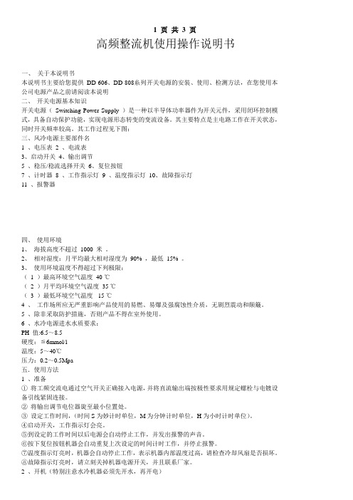
高频整流机使用操作说明书一、关于本说明书本说明书主要给您提供DD-606、DD-808糸列开关电源的安装、使用、检测方法,在您使用本公司电源产品之前请阅读本说明二、开关电源基本知识开关电源(Switching Power Supply )是一种以半导体功率器件为开关元件,采用闭环控制模式,具备自动保护功能,实现电源形态转变的变流设备。
其主要特点是主电路工作在开关状态,同时开关频率较高。
其工作过程见下图:三、风冷电源主要部件名1 、电压表2 、电流表3、启动开关4、输出调节5 、稳压/稳流选择开关6、复位按钮7 、计时器8 、工作指示灯9 、温度指示灯10、故障指示灯11 、报警器四、使用环境1、海拔高度不超过1000 米。
2、相对湿度:月平均最大相对湿度为90% ,最低15% 。
3、使用环境温度不得超过下列极限:( 1 )最高环境空气温度40 ℃( 2 )月平均环境空气温度35 ℃( 3 )最低环境空气温度-15 ℃4 、工作场所应无严重影响产品使用的易燃、易爆及强腐蚀性介质,无剧烈震动和颠簸。
5 、除非采取防护措施,否则产品不得在室外使用。
6 、水冷电源进水水质要求:PH 值:6.5~8.5硬度:≦6mmol/l温度:5~40℃压力:0.2~0.5Mpa五.使用方法1 、准备①将工频交流电通过空气开关正确接入电源,并将直流输出端按极性要求用规定螺栓与电镀设备引线紧固连接。
②将输出调节电位器旋至最小位置处。
③设定工作时间,(时间S为妙计时单位,M为分钟计时单位,H为小时计时单位)。
④启动开关,工作指示灯会亮。
⑤到设定的工作时间以后电源会自动停止工作,并发出报警的声音。
⑥按下复位按钮机器会自动重复上次设定的时间计时工作,并停止报警。
⑦温度指示灯亮时,机器会自动停止工作,表示机器内部温度过高,请检查冷却风扇是否损坏。
⑧故障指示灯亮时,请立刻关掉机器电源开关,并且联系厂家。
2 、开机(特别注意水冷机器必须先开水,再开电)闭合空气开关,检查风向或水路( 风冷方式时需检查风机旋转方向是否与标识方向一致,水冷方式时要检查水量是否符合要求) ,闭合启动开关,待工作指示灯亮后,根据工艺要求调节电位器,使电压表和电流表指示适当值。
高频高压电源设备使用说明书改版20060626
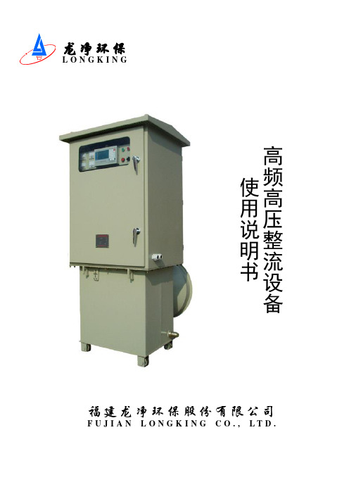
龙净环保 L O N G K I N G高频高压整流设备使用说明书福建龙净环保股份有限公司 F U J I A N L O N G K I N G C O ., L T D .目录第一章产品概述---------------------------------------------------------------------------------- 21、产品特点: -------------------------------------------------------- 22、工作原理 ---------------------------------------------------------- 43、产品构成 ---------------------------------------------------------- 4第二章主要技术性能和技术参数------------------------------------------------------------- 51、产品使用条件 ------------------------------------------------------ 52、主要技术参数 ------------------------------------------------------ 53、设备的功能 -------------------------------------------------------- 6第三章验收与安装------------------------------------------------------------------------------- 71、基本信息 ---------------------------------------------------------- 72、接收搬运储存 ------------------------------------------------------ 73、设备的安装 -------------------------------------------------------- 9第四章操作使用说明-------------------------------------------------------------------------- 101、设备的使用 ------------------------------------------------------- 102、控制终端操作和显示功能说明 --------------------------------------- 11第五章设备的调试----------------------------------------------------------------------------- 23 1、调试步骤 --------------------------------------------------------- 23第六章设备的维护保养----------------------------------------------------------------------- 241、正常运行维护 ----------------------------------------------------- 242、定期维护及保养 --------------------------------------------------- 25第七章产品的成套性和备件----------------------------------------------------------------- 25 第八章附录 ----------------------------------------------------------------------------------- 25第一章产品概述电除尘用高频高压整流设备(简称高频电源)可配套各类除尘设备广泛应用于电力、冶金、建材、轻工、化工等众多行业的烟气粉尘治理,是一种高效除尘、保护环境的重要设备。
高频机操作说明书
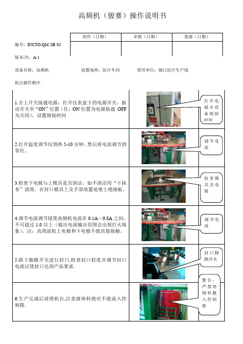
1.合上开关接通电源,打开仪表盒下的电源开,扳动开关至“ON”位置(住:ON位置为电源接通OFF为关闭),设置熔接时间
打开电源并设备熔接时间
2.打开温度调节仪预热5-10分钟,然后将电流调节到零位。
调节电流
3.检查下电极与上模具是否清洁。如不清洁用“干抹布”清理,在封口模具上及手部放置处垫上绝缘板。
制作(日期)
审核(日期)
批准(日期)
编号:INCTO/QM-SB-05
版本/次:A/1
设备名称:高频机放置场所:医疗车间使用单位:镇江医疗生产线
机台操作顺序
检查模具及电极
4.调节电流调节钮使高频机电流在0.1A—0.8A之间,不可超过1.0以上(超出电流输出范围会出现打火现象)。注:高周波机上电极和下电极不能直接接触。
调节电流
5.踩下脚踏开关进行封口,检查封口程度并调节封口电流以使封口达到产品要求.
警告:严禁将物料撒入控制箱
封口脚踏开关
6.生产完成后清理机台,注意液体料绝对不能流入控制箱.
高频感应加热机操作指导书
文件制修订记录1.0目的/Aim:1.1为操作者提供使用说明,确保使用者及设备的安全。
2.0参考文件/Reference Instruction:2.1 相关设备的操作说明书3.0设备/材料/ Equipment/Material:3.1 高频感应加热机 JF-254.0准备/要求/Prepare/Requirement:4.1确保输入电压为三相380伏,功率4KW。
5.0安全/维护/Safety/Maintenance:5.1 日常维护5.2.1 当设备出现故障时,请立即关闭电源并通知专职维修人员到现场检查。
5.2.2 未经培训且未经设备管理部门允许,请不要打开设备外壳触摸内部电路。
5.2.3 当发生异常情况时,请立即关闭面板上的开关,当异常情况排除后,方可将合上开关。
6.0操作程序/Operation Process:6.1 开机操作程序6.1.1先合上电源开关,再合上主机上的总电源开关,再合上面板上的开关。
6.1.2 打开冷却水,观察出水管有一定出水流量。
6.1.3将待加热工件放入感应圈中。
选择手动或自动工作状态。
6.1.4 手动操作规程A、将选择开关拔到手动位置B、调节加热功率旋钮至合适位置。
C、按一下操作面板的启动按钮,或踩下脚踏开关,开始加热;此时工作指示灯闪烁,机器嘀嘀响,数显表显示输出加热电流的大小,电流越大,加热越快,时间显示加热的时间。
D、按一下操作面板上的停止按钮,或松开脚踏开关,加热停止。
6.1.5 自动操作规程A、将选择开关拔到自动位置。
B、调节加热功率旋钮至合适位置。
C、设置加热、保温、冷却时间。
D、按一下操作面板的启动按钮,或踩下脚踏开关,开始加热;此时工作指示灯闪烁,机器嘀嘀响,加热灯亮,数显表显示输出加热电流的大小,电流越大,加热越快,时间显示加热的时间。
E、加热时间结束时,开始保温过程,此时工作指示灯继续闪烁,机器嘀嘀响,保温灯亮,数显表显示输出保温电流的大小,电流越大,加热越快,时间显示保温的时间。
高频感应加热设备使用说明书
750
20-25/0.02-0.03
φ24φ16
8
WH-VI-120
1100(三相)
20-25/0.02-0.03
φ24φ16
12
WH-VI-160
1100(三相)
20-25/0.02-0.03
φ24φ16
16
WH-VI-230
1100(三相)
20-25/0.02-0.03
φ24φ16
22
WH-VI-260
1
郑州高氏电磁感应加热设备有限公司
_______________________________________________________________________________________________
一、高频感应加热设备技术参数
型号
最大功 率输出
KW
工作频 冷却水 率 KHz 压 MPa
1100(三相)
20-25/0.02-0.03
φ24φ16
24
3、环境需求
设备工作环境应无易燃易爆粉尘,无导电粉尘,无腐蚀性气体。 海拔高度≤2500 环境温度 2-40℃,相对湿度≤85%。 保证设备工作场合通风良好,以保证设备的正常通风冷却。 本设备不能在凝露状态下工作。
四、高频感应加热设备安装
2、冷却水要求
进水压力:≥0.05MPa 进水温度:5-35℃,当冷却水温度低于室温时,其温差应小于 10℃。湿度较大时其温差应小
于 5℃,以防止设备暴漏。 进水 PH 值:7-8.5
硬度:不大于 60mg/L
冷却水系统配臵
按每天工作 8 个小时,室温 25℃计,若工作时间加长,可以适当增加水池容积。如果选用的 水泵是自吸泵,则应适当加大水泵功率。
高频开关电源说明书
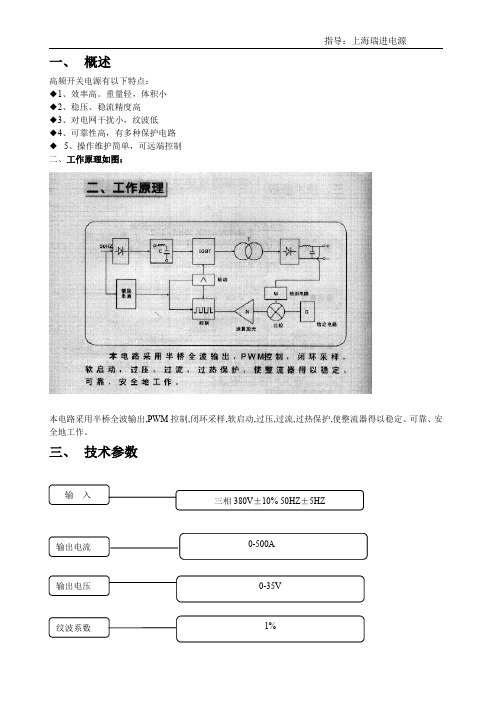
输入
三相 380V±10% 50HZ±5HZ
输出电流 输出电压 纹波系数
0-500A 0-35V 1%
调整精度 冷却方式
指导:上海瑞进电源 1%
风冷
四、 功能选配
项目
基本功能
启动/停止
○
稳压/稳流选择
○
电压表
表
异常报警
○
远程控制
软启动
○
PLC 控制
128-485
户所需功能置稳压或稳流档. 2. 合上空气开关,此时面板上数显表显示. 3. 将"待机"开关置"工作"状态,然后顺时针转动输出调节旋钮.电压和电流显示出相应的数字. 三.开关功能:
本机具有稳压和稳流功能.当用户置"稳压"档时,输出电压在机器额定电流范围内不会有变化, 电流会根据负载大小做相应的显示.当用户置"稳流"档时输出电流在机器额定电压范围内不会有任何 变化,电压表会根据负载大小做出相应显示。
五、 共同规格
控制方式
PWM 控制切换方式
输入端
电压 频率
38V 三相 50/60HZ
电压范围 ±10%
控制
稳压、稳注
输出端
可调范围 0-额定位(电流,电压)
精度
额定位±1%
误差
RMS1%
六、 机器型号
500
A
产品标号
选项配功能
高频电源 机器名称
输出电流表
产品系列
七、 安装与使用 ◆ 1、把整流器安放好,并保持其稳定,为保证整流器通风良好,其前后左右 0.5m 以内不要有任何物
四、注意事项:
1、保护指示灯亮时:
①、检查输入 380V 交流是否缺相,电压是否高于 440V 或低于 320V;
高频发生器使用说明书

4642 N. RAVENSWOOD, CHICAGO, ILLINOIS 60640-4510TELEPHONE: 1-773-561-2349FAX: 1-773-561-3130Model BD-10A /BD-10AS HIGH FREQUENCY GENERATORPRODUCT NUMBER 11011 / 11031INSTRUCTIONSDESCRIPTION. The Model BD-10A and BD-10AS are hand-held units which generate a high voltage at a high frequency. It is intended for intermittent use, no more than 10 minutes at a time. It has an output of between 20,000 to 45,000 volts, at a frequency of approximately 500 kHz. When properly adjusted, when the electrode is held within ¼ to 1 in. (6 to 25 mm) from a metal object, a spark will jump to the metal. Current output of the spark is about 1 mA.The Model BD-10AS (illustrated above) has a button on the side, which when pressed turns on the high voltage side of the coil. When it is depressed, the high voltage is turned off. The Model BD-10A does not have this feature.Both models are a variation of the tesla coil. They have a primary coil which produces an output voltage of about 1200 V at the input line frequency, 50 or 60 Hz. This output voltage is interrupted by a vibrating contact, energized by this coil at twice the line frequency. The output voltage of this primary coil is connected to capacitors, which are then discharged into a high voltage coil.The capacitance, resistance and inductance of this circuit is designed to oscillate, or ring, at a very high frequency, in this case 500 kHz. The output of this high voltage coil is adjustable by varying the distance of the vibrating contacts, which is user adjustable, by means of a knob on the end of the unit.Applications include pinhole leak detection, as in the linings of tanks and other similar metal objects, and in plastic welds, where a test metal backing is applied. Other applications include ionizing a gas inside a lamp, neon sign, double-pane insulated window, pharmaceutical vial, or similar glass vessel where a deep vacuum is contained.03/11Four models are available for different input voltages:Model BD-10A, 115 V, 50/60 Hz, with 12101 Electrode Tip.Model BD-10AV, 230 V, 50/60 Hz, with 12101 Electrode Tip.Model BD-10AS, 115 V, 50/60 Hz, with Switch and 12101 Electrode Tip.Model BD-10ASV, 230 V, 50/60 Hz, with Switch and 12101 Electrode Tip. INSTALLATION. A standard tip electrode, Part No, 12101, illustrated above, but not below is included with each model. To install it, press it into the tip of the generator handle. To remove, grasp its base firmly, and with a gentle rocking motion, pull out from the generator tip. Never insert or remove the electrode while power is on.Accessory Electrodes for the Model BD-10A/BD-10AS12111 Spring Tip 12121 T-Tip 12131 T-Tip, 12 in. Wide 12141 Fan Tip 12401 Brush Tip 4-1/4 in. Wide 4 in. Wide12421 Brush Electrode, 8 in. WideThese electrodes, plus the 12101 Standard Tip, are the only factory approved electrodes for the Model BD-10A/BD-10AS. No other electrodes should be used. After the electrode is inserted, plug the power line cord into its matching receptacle, providing the proper voltage for the unit, either 115 V or 230 V.OPERATION.1) Turn the Output Adjustment Knob fully counterclockwise.2) Turn the Output Adjustment Knob clockwise to adjust the voltage forthe desired spark length. Hold the tip close to a metal object, toobserve and adjust the length of the spark.3) For pinhole detection of thick materials, the spark should be adjustedfor near maximum length. For thinner materials, a shorter spark isdesired. A one inch spark represents a peak voltage of approximately50,000 volts. For materials less than 1/8 in. (3 mm), use the ModelBD-40E or Model BD-60. For vacuum leak checking, an output nearthe maximum is usually required to ionize (glow) the gas inside thecontainer.4) Once the unit is adjusted, pass the electrode over the material beingtested. The electrode can be passed directly over most materials,however, with thin linings or glass, keep the electrode no more than1/8 in. above the surface being tested.5) When the electrode passes over a pinhole, crack, or similar type flaw,observe a bright, concentrated spark jumping from the electrode to themetal, or similarly conducting surface below the lining or coating.Do not use the Voltage Adjustment Knob as an “ON/OFF” switch forthe high voltage, as this will prematurely wear this part. Never leaveeither model connected to the power line unattended. Remove fromthe power line when not in use. Use of a power strip with ON / OFFSwitch is recommended.If the output level of the Model BD-10A/BD-10AS is required to be verified when this instrument is in use, check the output with a Model 12701 Peak Voltage Calibrator, shown below.THEORY OF OPERATION. The output of the Model BD10A/AS is adjusted by changing the gap between two contacts, one vibrating due to the magnetic pull and push from a coil, and the other connected to a screw with black knob at the end of the unit. The vibrating contact assembly consists of the contact, spring, and metal plug to which the magnetic field attracts and repels. The other contact assembly is held in place by a flexible spring connected to a shaft and the black control knob. Its position is determined by the adjustment, in or out, of the connecting shaft.Both contact assemblies must make contact to energize both the magnetic and high voltage coils and capacitor, but must also allow this contact to break when the vibrating contact is pulled away by the attracting force portion of the alternately attracting/repelling magnetic field. This action of making and breaking these two contacts sets up an oscillation in the circuitry, generating the high voltage at a high frequency (of 500 kHz).If the gap between the contacts is too large, no contact will be made, the circuits will not be connected; the unit will not generate the high voltage. If the adjusting shaft is turned clockwise too much, both contacts will be pressed together towards the magnetic coil, but the spring tension on the vibrating contact will be too great for the attracting magnetic field to overcome. Hence, the contacts will not break contact, and the unit will not produce the high voltage.Once the contact gap is adjusted properly to make and break the connection between contacts, the distance can be adjusted, to a limited range, to vary the output of the voltage, the greater the gap the lower the voltage, and vice versa. However, the gap distance is also affected by the pull of gravity of the metal plug of the vibrating contact, especially at the lowest output level. If, for example, if the unit is adjusted to resonate while the unit is held horizontally, if then positioned to point downward, the gap distance will increase, breaking the connection between contacts. If the unit is then held vertically upward, the gap distance decreases, making the connection again between the contacts.For example, if the Model BD-10A/AS was set for an output voltage near the low range of operation, at the horizontal position, it might have an output of 23 kV, but be intermittent, cutting out on occasion, if held with the switch pointing down, and continuous if the switch was held upright. When held pointing down, the unit might no longer generate an output. When held pointing up, the unit might generate a voltage of 27 kV, with a continuous output.Normally, units should be adjusted to function in the orientation in which it is used, or adjusted to operate at the higher output level, where the orientation issue is not as much a problem.Alternately, the Model BD-50E is recommended. The vibration contacts are inside a power control unit, and are always horizontal when the power control unit is placed on a horizontal surface. The high voltage coil is held in the black-plastic housing. It can be held in any position without affecting the position of the contact gap. In fact the contact gap is factory set for optimal performance, and the output is changed by a 9-step switch, with positions marked on the power control unit front panel. This also makes the calibration of this unit more positive, and repeatable, then the Model BD-10A/AS.For voltage ranges below 20 kV, another option is the Model BD-40E. It uses solid-state circuitry, instead of vibrating contacts to adjust the voltage and set upSAFETY PRECAUTIONS. It is used in industrial applications for pinholeleak detection, and to ionize a gas inside a lamp, neon sign, vial or similardevice to determine whether a good vacuum is being held inside thedevice. It is also used as a lamp starter, principally in printing industry.Only factory approved electrodes should be used. No other electrodes should be used with this device.Never touch or come in contact with the high voltage output of this device, nor with any device it is energizing.Since its output is 500 kHz, it radiates its energy for a short distance. It may interfere with sensitive electronic devices near by. If a user is wearing a pace maker or similar device, their physician should be contacted prior to using this device. The same should be said for women who are pregnant.Also, a small amount of ozone gas is generated as a by-product. Use in a well-ventilated area.Special Notice Regarding CE Marking. The Model BD-10AV/BD-10ASV generates a high voltage corona of approximately 500 kHz.However by the very nature of its design, it will produceelectromagnetic interference (EMI) as a result of its operation.Electric arc welders, for example, are another product that by its very nature and mode of operation produces EMI.As a result, the Model BD-10AV/BD-10ASV cannot meet the European Union Electromagnetic Compatibility (EMC) Directive 89/336/EEC, and cannot be CE marked.It does, however, meet EN61010-1:1993 Safety Requirements for Electrical Equipment for Measurement, Control and Laboratory Use, following the provisions of the Low Voltage Directive 73/23/EEC, as amended by 93/68/EECBecause of the risk of EMI, a risk assessment should be carried out prior to use of this equipment.The power output of the Model BD-10 is limited. The effective range of EMI is less than about 1 meter on so in all directions. Metal objects nearby may bend or deflect this radiation. Therefore, there is some risk that it might interfere with electronic equipment 1 meter or so from this apparatus. This might include telephones, computers, cell phones, for example. Operators who wear pacemakers may also wish to consult with a physician prior to using this equipment.If interference with equipment is detected, move the Model BD-10 further away,or schedule its operation when the affected equipment is not in operation. Consult plant safety personnel regarding its use.If you should have any further questions, contact Electro-Technic Products, Inc. for additional technical assistance.REPAIR. There are no user serviceable parts inside the unit. In the event that the unit requires service, send it back to the factory. However, parts are available separately, so an experienced electronics technician can make repairs. The following troubleshooting guide is furnished:Disassembly Instructions:With the power removed from the unit, remove the electrode tip, and the remove the 10-32 hex nut by using the special 5/16 in. nut driver, P/N 049-0025-1. Then remove the top half (smooth cone portion) of the plastic housing by turning it counterclockwise.Turn the black adjusting knob counterclockwise and remove it by holding the brass adjusting screw with the special 3/16-in. wrench, P/N 049-0026-1 and turning the knob counterclockwise. Save the plastic and fiber washers. The number of washers may vary from one unit to another.On each side of the adjusting screw are two metal screws covered by wax. Remove and save the wax, and remove the screws.Slide the rear plastic housing back and expose the internal parts of the unit. During this operation, for the Model BD-10AS, pull the black plastic button up to avoid interference while the housing is being removed.Troubleshooting:Observe the adjusting screw for worn threads. Replace if this is observed. Note that on Model BD-10A (unit without switch), some customers incorrectly use the adjusting knob as an “ON/OFF” switch. This practice prematurely wears out the threads. Customers must be warned not to do this, but do use a power strip or similar device to turn the unit on and off.Next observe the contacts. They must be aligned to each other’s center as much as possible, and must be corrosion and burn-spot free. If corrosion or burn spots are observed, clean with a fine file, or replace. Make sure the bottom contact has enough room on the bottom, so that when the top spring is pushed against it, the bottom contact does not get pushed into the molded spool core.Use a multimeter to check the power cord for any broken wires. Replace if it is found that the customer has used tape to cover frayed insulation.Check the magnet coil for broken wire leads. Use an ohmmeter to measure the resistance of the magnet coil. If the coil resistance is zero (open), replace it.Check the yellow capacitor using an ohmmeter. Check for broken leads. If power is applied to the unit, and it makes a knocking sound (from the armature bottom spring making contact with the spool core), but there is no output, the capacitor is bad. Replace it if any of these conditions are present.Use an ohmmeter to check the resonator coil. If no resistance, check for broken lead wires, or replace the resonator coil. If the unit is powered, and arcing is observed inside the resonator coil, replace it. If the unit works Okay, but has a weak output, the resonator coil is defective. Replace the resonator coil if any of these conditions are present.The Model BD-10AS has a microswitch to turn power on and off to the resonator. Check the switch for broken wire leads. If leads are Okay, test the switch for continuity with a multimeter. Replace if bad.If the unit is working, but the output is reduced, check the resonator coil, the capacitor, and the contacts.Assembly Instructions:For the Model BD-10AS, make sure the microswitch aligns with the pushbutton.Install the plastic housing, 10-32 nut, and screws to the proper position.To avoid a potential shock hazard, cover the screws with wax as before.Install the adjusting knob on the adjusting screw. Turn the knob clockwise until the unit turns on. Turn the knob clockwise until it shuts off. Back up the knob until the unit turns on again. Remove power from the unit and install the plastic or fiber washers into the space between the plastic housing and the adjusting knob. Tighten the knob securely.The unit should sound smooth when turned on. If the adjusting knob is turned too far into the unit, a loud vibration will be heard, the output will be high. If left in this position, the internal parts will begin to burn up. Back off the knob to the position which has a smooth sound.If the contacts were replaced, the number of adjusting washers may vary with what was used before contact replacement. If the contacts were not replaced, the same number of adjusting washers can be used.REPAIR PARTS. The following are repair parts for the BD-10 models. Contact Electro-Technic for price and availability. These parts can be ordered on-line from our e-commerce section of our web site.Part Number Description12101 Electrode Tip002-0005-1 Nut, 10-32, Hex, for Electrode Socket011-0008-1 Magnet Coil, Model BD-10A, 115 V011-0009-1 Magnet Coil, Model BD-10AV, 230 V011-0010-1 Magnet Coil, Model BD-10AS, 115 V011-0011-1 Magnet Coil, Model BD-10ASV, 230 V011-0018-1 Magnet Coil, w/Capacitor & Spool Head011-0024-1 Resonator Coil021-0003-1 Capacitor, 0.1 uF, 1000 V029-0012-1 Micro-Type Switch, BD-10AS Models035-0001-1 Bridge w/Posts, Ratchet Spring, Adjusting Screw(Top Assembly)035-0003-1 Top Spring Rivet Contact Assembly035-0007-1 Armature Assembly035-0011-1 Adjusting Screw Assembly040-0030-1 Bridge Yoke & Bushing044-0003-1 Top Housing, Cone, Models BD-10A, BD-10AS044-0004-1 Bottom Housing, Model BD-10A044-0005-1 Adjusting Knob044-0017-1 Cord Clamp044-0018-1 Bottom Housing, Model BD-10AS044-0027-1 Molded Switch Base, BD-10AS Models044-0028-1 Molded Button, BD-10AS Models044-3007-1 Molded Spool Core, BD-10A Models044-3031-1 Molded Spool Core, BD-10AS Models045-0003-1 Electrode Socket049-0025-1 Nut Driver, 5/16 in.049-0026-1 Wrench, Small, 3/16 in.050-0037-1 Tungsten Screw Contact051-0001-1 Teflon-Type Spacer, Electrode Tip060-0002-1 Line Cord Set, 3 Conductor, 115 V060-000X-1 Line Cord Set, 3 Conductor, 230 V, Specify Type070-0004-1 Carton, Packing, with Inserts083-0001-1 Housing, Bakelite, Complete, BD-10A Models083-0011-1 Housing, Bakelite, Complete, BD-10AS Models。
高频感应加热设备 GP-20 使用说明书
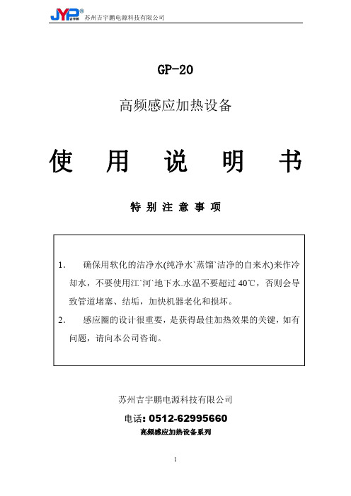
GP-20高频感应加热设备使用说明书特别注意事项1.确保用软化的洁净水(纯净水`蒸馏`洁净的自来水)来作冷却水,不要使用江`河`地下水.水温不要超过40℃,否则会导致管道堵塞、结垢,加快机器老化和损坏。
2.感应圈的设计很重要,是获得最佳加热效果的关键,如有问题,请向本公司咨询。
苏州吉宇鹏电源科技有限公司电话:高频感应加热设备系列1.简介本公司的手提式高频感应加热设备是采用国际最先进的电力电子器件和独特的变流控制技术以合理的结构设计而形成的最新高科技产品,从而开辟了感应加热设备的新领域。
其主要优点如下:⑴体积小、重量轻:占地面积小,节省厂房空间⑵特别省电:同样加热速度,用电仅为电子管高频机的三分之一⑶操作简单:几分钟即可学会⑷安装简单:接电源和水即可使用,5分钟即可完成⑸特别安全:无近万伏高压,免除高压触电危险2.产品规格说明产品规格定义:GP-XX YY其中XX为数字,表示设备的最大振荡功率或最大输出功率;YY为英文字母,表示设备的附加功能,这些附加功能含义如下:附加功能YY附加功能说明附加功能功能说明A自动控制型1、加热、保温、冷却三个过程可自动转换2、加热功率、保温功率、加热时间、保温时间、冷却时间五个参数可独立调节3、适合于对加热温度要求比较精确的使用场合,如热处理等B分体式1、高频变压器单独引出,与主机用软线相连,软线长1.5米2、适合于可达性差的应用场合自动流水线或手工现场作业C超高频型输出振荡频率为150-250KHZD锻造加强型100%负载持续率设计,专为锻造不停机使用场合设计一、GP-20(A)(B)系列产品适用范围1.适用于焊接面积在10CM2以内的各种合金刀具、钻头、金刚石工具的快速加热焊接,具有很大范围的适用性,能满足绝大多数刀具、工具的高频感应加热要求。
如焊接面积为10CM2面积刀具,焊接时间为银焊约30-40秒,铜焊约60-100秒。
通过合理的感应圈设计,可以焊接面积在10-20CM2的工件,但焊接时间相对较长,遇此情况,请接受本公司技术咨询。
高频机说明书(6.0KW最新版)
CW-XJH-3.2KW,CW-XJH-4.5KW,CW-XJH-6.0KW单头超高频感应加热焊接机使用说明书1、输入电源电压:220V AC单相2、冷却水水质要求:水质清洁,水温<30℃,水压>0.3MPa。
一、前言CW-XJH-3.2KW,CW-XJH-4.5KW,CW-XJH-6.0KW型超高频加热焊接机,是我公司独家开发研制生产的一种高新技术产品,体积小,功率高,在首饰,小五金,电子,模具,玩具,机床刀具,灯饰,锯片等制造行业中,是电子管高频焊接机升级换代的最新产品,该机广泛应用于焊接高档眼镜框架,金银首饰及各种小配件,钓具.薄板和纤细线材,锯片等焊接处理,也适用于金属材料表面热处理加工.二、技术条件1.CW-XJH-6.0KW2.输入电源:220V AC静态输入功率<90W满载输入功率=6.0KW3.高频输出功率:6.0KW频率: 1100-2000KHZ功率连续可变0-99%4.工作环境:温度0-40℃湿度<98%(无凝水)5.体积:主机320×210×330MM高频头240×130×115MM6.重量:19kg7.水压要求:>0.3Mpa8.工作方式:断续要求清洁,进水温25℃以上,40℃以下,否则会导致机器损坏.(用冷水机来冷却循环水的用户特别注意水温不能低于25℃,以免机内结露造成元件短路损坏机器,影响生产。
)四、系统结构(1)前面板(2)后面板(3)分机后板0.工作1.频率捕捉2.水压报警3.水温报警4.功率显示 5.功率设置6.脚踏开关插头7.船形开关8.电源线9.空气开关10.高频输出11.主机进水12高频输出13.主机出水14分机进水15分机进水五、故障现象与排除安装维护指南第一部分:冷却水安装维护一、安装1、冷却水连接:(1)对冷却水的要求:水冷却对感应加热设备极其重要,水质不好,将导致设备内部产生锈蚀、结垢、堵塞,将直接导致设备损坏。
高频机说明书(中文版)
ห้องสมุดไป่ตู้型号
型
1K
号
对
2K
照
表
3K
6K
备注 外接电池长效机型 外接电池长效机型 外接电池长效机型 外接电池长效机型
第 1 页 共 42 页
型号 1KB 2KB 3KB 6KB
备注 内置电池标准机型 内置电池标准机型 内置电池标准机型 内置电池标准机型
10K 3 相 10K 3 相 15K 3 相 20K
1-20K 用户说明书
2.1 产品外观图
1-20K 用户说明书
Fig. 1 1K(B) 后盖板图
Fig. 2 2K(B)/3K(B) 后面板图
RS232 接口 风扇 输入空开 接线端子台
RS232 接口 智能卡插槽
并机卡盒
风扇
维修开关
输入空开
接线端子台
智能卡插槽 并机卡盒
维修开关
第 6 页 共 42 页
Fig. 3 6K(B) 后盖板图
附录一 有毒有害物质或元素表 .......................................................... 41
第 1 章 安全说明
本章主要介绍 PHS 系列在线式不间断电源的安全标志和安全注意事项,在进行任何有关设备的操作之前,需 要仔细阅读本章内容。
1.1 安全说明
危险:
第 4 页 共 42 页
1-20K 用户说明书
表示若忽视安全告诫,就有可能发生人员伤亡或设备损坏的重大事故。 警告:
表示若忽视安全告诫,就有可能发生重大或严重伤害事故,或损坏设备。 注意、小心:
表示若忽视安全告诫,就有可能发生伤害事故,损坏设备。
第 5 页 共 42 页
高频机说明书(KW最新)
CW-XJH-3.2KW,CW-XJH-4.5KW,CW-XJH-6.0KW单头超高频感应加热焊接机使用说明书1、输入电源电压:220V AC单相2、冷却水水质要求:水质清洁,水温<30℃,水压>0.3MPa。
一、前言CW-XJH-3.2KW,CW-XJH-4.5KW,CW-XJH-6.0KW型超高频加热焊接机,是我公司独家开发研制生产的一种高新技术产品,体积小,功率高,在首饰,小五金,电子,模具,玩具,机床刀具,灯饰,锯片等制造行业中,是电子管高频焊接机升级换代的最新产品,该机广泛应用于焊接高档眼镜框架,金银首饰及各种小配件,钓具.薄板和纤细线材,锯片等焊接处理,也适用于金属材料表面热处理加工.二、技术条件1.CW-XJH-6.0KW2.输入电源:220V AC静态输入功率<90W满载输入功率=6.0KW3.高频输出功率:6.0KW频率: 1100-2000KHZ功率连续可变0-99%4.工作环境:温度0-40℃湿度<98%(无凝水)5.体积:主机320×210×330MM高频头240×130×115MM6.重量:19kg7.水压要求:>0.3Mpa8.工作方式:断续要求清洁,进水温25℃以上,40℃以下,否则会导致机器损坏.(用冷水机来冷却循环水的用户特别注意水温不能低于25℃,以免机内结露造成元件短路损坏机器,影响生产。
)四、系统结构(1)前面板(2)后面板(3)分机后板0.工作1.频率捕捉2.水压报警3.水温报警4.功率显示 5.功率设置6.脚踏开关插头7.船形开关8.电源线9.空气开关10.高频输出11.主机进水12高频输出13.主机出水14分机进水15分机进水五、故障现象与排除安装维护指南第一部分:冷却水安装维护一、安装1、冷却水连接:(1)对冷却水的要求:水冷却对感应加热设备极其重要,水质不好,将导致设备内部产生锈蚀、结垢、堵塞,将直接导致设备损坏。
[VIP专享]高频高压电源设备使用说明书改版20060626
![[VIP专享]高频高压电源设备使用说明书改版20060626](https://img.taocdn.com/s3/m/f0c8e98428ea81c758f57898.png)
龙净环保LONGKING高频高压整流设备使用说明书福建龙净环保股份有限公司FUJIAN LONGKING CO., LTD.目录第一章产品概述----------------------------------------------------------------------------------21、产品特点:---------------------------------------------------------22、工作原理-----------------------------------------------------------43、产品构成-----------------------------------------------------------4第二章主要技术性能和技术参数-------------------------------------------------------------51、产品使用条件-------------------------------------------------------52、主要技术参数-------------------------------------------------------53、设备的功能---------------------------------------------------------6第三章验收与安装-------------------------------------------------------------------------------71、基本信息-----------------------------------------------------------72、接收搬运储存-------------------------------------------------------73、设备的安装---------------------------------------------------------9第四章操作使用说明--------------------------------------------------------------------------101、设备的使用--------------------------------------------------------102、控制终端操作和显示功能说明----------------------------------------11第五章设备的调试-----------------------------------------------------------------------------23 1、调试步骤----------------------------------------------------------23第六章设备的维护保养-----------------------------------------------------------------------241、正常运行维护------------------------------------------------------242、定期维护及保养----------------------------------------------------25第七章产品的成套性和备件-----------------------------------------------------------------25第八章附录-----------------------------------------------------------------------------------25第一章产品概述电除尘用高频高压整流设备(简称高频电源)可配套各类除尘设备广泛应用于电力、冶金、建材、轻工、化工等众多行业的烟气粉尘治理,是一种高效除尘、保护环境的重要设备。
- 1、下载文档前请自行甄别文档内容的完整性,平台不提供额外的编辑、内容补充、找答案等附加服务。
- 2、"仅部分预览"的文档,不可在线预览部分如存在完整性等问题,可反馈申请退款(可完整预览的文档不适用该条件!)。
- 3、如文档侵犯您的权益,请联系客服反馈,我们会尽快为您处理(人工客服工作时间:9:00-18:30)。
CW-XJH-3.2KW,CW-XJH-4.5KW,CW-XJH-6.0KW单头超高频感应加热焊接机使用说明书1、输入电源电压:220V AC单相2、冷却水水质要求:水质清洁,水温<30℃,水压>0.3MPa。
一、前言CW-XJH-3.2KW,CW-XJH-4.5KW,CW-XJH-6.0KW型超高频加热焊接机,是我公司独家开发研制生产的一种高新技术产品,体积小,功率高,在首饰,小五金,电子,模具,玩具,机床刀具,灯饰,锯片等制造行业中,是电子管高频焊接机升级换代的最新产品,该机广泛应用于焊接高档眼镜框架,金银首饰及各种小配件,钓具.薄板和纤细线材,锯片等焊接处理,也适用于金属材料表面热处理加工.二、技术条件1.CW-XJH-6.0KW2.输入电源:220V AC静态输入功率<90W满载输入功率=6.0KW3.高频输出功率:6.0KW频率: 1100-2000KHZ功率连续可变0-99%4.工作环境:温度0-40℃湿度<98%(无凝水)5.体积:主机320×210×330MM高频头240×130×115MM6.重量:19kg7.水压要求:>0.3Mpa8.工作方式:断续要求清洁,进水温25℃以上,40℃以下,否则会导致机器损坏.(用冷水机来冷却循环水的用户特别注意水温不能低于25℃,以免机内结露造成元件短路损坏机器,影响生产。
)四、系统结构(1)前面板(2)后面板(3)分机后板0.工作1.频率捕捉2.水压报警3.水温报警4.功率显示 5.功率设置6.脚踏开关插头7.船形开关8.电源线9.空气开关10.高频输出11.主机进水12高频输出13.主机出水14分机进水15分机进水五、故障现象与排除安装维护指南第一部分:冷却水安装维护一、安装1、冷却水连接:(1)对冷却水的要求:水冷却对感应加热设备极其重要,水质不好,将导致设备内部产生锈蚀、结垢、堵塞,将直接导致设备损坏。
此外,设备内部若干带电部分因需水冷却而使水带电,水质不好,将增加产品触电的危险。
(2)对冷却水的技术要求:●水流量;≥6L/min●最小水压力:0.2MPa●进水口最高温度:35℃●水质要求:PH值在2.0—9.0之间(即略显碱性)氯化物含量<20PPm硝酸盐含量<10 PPm碳酸钙含量<250 PPm25℃下的电阻率>2500 Ω.CM总溶解固体杂质含量<250 PPm无固体杂质析出的温度T<57℃必要时加入消磁剂,防腐剂以及二乙醇(含量最多千分之四)的抗凝剂。
a)推荐使用冷却水:蒸馏水——软化水——纯净水——经过滤的自来水b)严禁使用的冷却水:海水、盐水、未经过滤的河水和井水c)推荐供水方式:封闭循环供水+水冷却热交换器d)冷却水与设备的连接i.连接进水管至设备(主机)后部,连接出水管到设备(主机)后部,并用喉箍锁紧C、分别连接进出水到感应圈二、冷却水的作用:1)冷却感应线圈2)冷却感应加热设备内部功率组件和高频变压器三、冷却水的要求:1)进水口水温:<40℃2)压力:>0.2Mpa3)流量:5-10L/分,出水口最高水温不超过70℃4)水质:洁净的软化水四、冷却水的水质至关重要.保修期内,由于水不合以上及如下要求而损毁机器,不属于保修范围,而列入维修收费范围。
如水中带有泥沙、铁锈、纤维、毛发等物将严重堵塞设备冷却管道,造成水流量小,降低冷却效果,引起设备内部功率器件烧损,管道烧穿,造成停工停产。
高硬度水质或石灰岩水质中含有大量的钙、镁等离子,长时间工作,设备内部的散热器及冷却管道中将形成厚厚的水垢,堵隔水的冷却作用,同样会导致设备内部功率器件烧损。
一、常用的冷却水系统1、自来水—直接用自来水作冷却水,出水流走,这种方法最简易,但长期使用时易造成浪费。
建议用于设备不常用的场合。
图12、封闭循环供水—客户自建一个储水箱或储水池,用水泵对设备进行供水,设备出水再流回水池。
见下图。
这种冷却水方法比较常用,即省水又简单易行。
但是水池一定要定期续水,每月彻底清洗换水,以保证水池中的水洁净,不易结垢。
水池体积要足够大,以保证水池的水温低于40℃。
水池的体积和水泵的参数,根据设备功率大小和设备工作时间来定,参考如下:图2 1、闭循环供水+水冷却热交换器:图32、冷水装置-----用专业的冷水装置,保持水温工作在25℃左右,对设备有最好的冷却效果,如果资金允许,应该是首选。
使用冷水机后,可大大降低设备的故障率。
用冷水机时水温不可调得太低,一般控制在25℃左右,如果太低,低于水的露点后,会在设备内部结露,引发绝缘下降和打火等故障;3、适用于普通水质,屡去泥沙,但过滤效果相对较差。
水阀图46、净水或滤水装置的滤芯请及时清理或更换。
设备冷却水安装中的几个问题设备需要水冷的分以下几个部分:1、感应圈2、逆变器和功率件3、高频变压器。
其中,冷却感应器的出水很热,其它出水不会有明显的温升,所以条件允许的话,将感应器冷却出水和设备冷却出水分开。
以防高温对设备产生损害。
对于水质较差的用户,可单独为设备内部冷却提供较好的冷却水,防止功率器件损坏,感应器冷却用一般水即可。
如图所示:图5设备出水不要连接在一起。
冷却水箱高出出水口时的处理方法1、当冷却水箱放在房顶,设备回水要流回水箱,反回的压力很大,对设备的冷却效果大大降低。
2、整个冷却水系统压力大,流速小,水温高,容易引起设备内部水管爆裂而毁坏设备。
第二部分设备安装环境及维护一、设备的使用环境要求1、清洁,通风良好。
2、无腐蚀性气体3、无金属粉尘4、无潮湿,无高温。
二、恶劣环境引发的设备问题设备内部全部都是电子线路,尽管大多数零件都已做了很好的绝缘防潮处理,但有部分零件如电路板,功率器件的接头部位等,无法进行绝缘处理。
而设备周围存在的腐蚀性气体,金属粉尘、水分等都会引发绝缘下降,造成设备内部打火,继而引发更大的设备损坏,以下是几种常见的恶劣环境分析;1、腐蚀性气体如清洗金属用的硝酸溶液,挥发在空气中对设备内部的电路板有强烈的腐蚀作用,会极大的增加设备的故障率。
2、金属粉尘当空气中的金属粉尘处理不当,进入设备后容易引起短路,从而造成设备容易损坏。
3、潮湿天气时,或热处理等工作场合,由于喷水或喷淬火液,造成设备周围湿气很大,设备内部零件上都会凝结水珠,造成设备内部绝缘下降,引发设备内部打火等故障,严重时,会造成主要功率器件损坏,造成很大的损失。
4、高温设备内部电子组件如半导体组件,电容等损坏温度约为85℃—125℃,设备工作时,所有内部组件都会发热而使设备内部温度升高,当设备受到辐射,日光曝晒或工作环境温度过高时,由于散热条件不好,会引起设备内部组件温度过高而引发损坏。
三、设备日常维护针对以上这些问题,为保证设备正常使用,节省维护成本,减少维护带来的损失,要求对设备进行合理的预防性维护。
1、安装足够的通风设施,保持工作环境清洁。
2、选用分体设备,将主机隔离在离污染源较远的地方。
3、将设备外壳全部封住,去掉设备内部风扇,尽量减少有害气体的侵入。
4、潮湿季节使用设备时,要注意以下几点:A、设备放置几天后,重新用时,先打开设备外壳,用吹风稍微烘干。
或者先将设备电源打开一个小时后,再启动加热。
B、短时停工或晚上放工时,可不关掉电源,保持设备风扇继续工作。
C、每周开机检查设备,如果发现设备内部水垢请及时处理。
5、定期对设备进行开机维护,保持设备内部清洁;但设备的维护工作由专业电工来进行。
6、采用我公司配送的脚踏开关或遥控盒来控制设备,减少设备面板上按钮的使用几率,避免操作者人为造成对面板损坏。
第三部分设备电力安装及维护设备电力安装的几个参数:1、配电量针对所购买的设备,要选用足够的电力容量,如果电力容量不足,可能会导致设备工作时,电压不稳定或电压过低,使设备无法正常工作。
2、工作开关请按设备安装图上要求,选用合适的开关和保险丝。
建议选择合适的空气开关。
选择空气开关时要注意与设备相匹配达到正常的开关和保护作用。
3、电源线按照设备安装图上的要求,选用铜电缆作为设备电源线。
电缆线线径要足够与设备匹配。
建议使用国标电缆线作为电源线。
4、安装电缆时注意事项A、安装人员应具备从事电工经验。
B、安装设备电源线时,要用线鼻子将电缆压紧后,用铜螺丝紧紧固定在电源接线柱上。
C、从供电箱或变压器的接头,应采用正确的连接方法,确保连接的稳定性和可靠性。
D、要选用足够大的线鼻子,和足够大的铜连接螺丝。
E、单相电220V连接时,一端要接零线,不能接在水管上用地线来代替;第四部分设备修理1、设备的修理,必须由专业的电工来进行。
2、设备出现故障时,请按以下方法进行A、先将设备功率调到最小。
B、去掉脚踏开关等外围其它控制仪器。
C、自控型设备,将设备置于手动工作状态。
D、按照设备说明书之简易故障指南来操作。
E、在上述状态下,试验设备,按说明书指引,确定发生故障的性质,然后致电我公司维修部专业人员。
1112。