英文芯片数据手册阅读技巧
芯片数据手册Datasheet热门问题

芯片数据手册Datasheet热门问题∙如何正确的阅读Datasheet?不仅仅是芯片,包括工具、设备几乎任何电子产品,都需要去阅读它的datasheet,除了包括最低、最高要求,特点,建议和用途及其兼容的设备等等,更重要的是原厂商以一个成功者的身份去告诉你一些注意事项。
Datasheet一般组成的字段:(LM317举例)①日期:首先检查发布日期,是预备版还是修正版②厂商:检查厂商,因为相同型号不同厂商的器件,性能或许不同③描述(Description):往往会告诉你一些一般地方没有提到的功能或者用法。
比如:你可能需要保持一个特殊的引脚为低电平才能完成某个操作。
④特点(Features):告诉你常规特征。
确认电器特征相应的条件⑤应用(Application):通常简洁的告诉你该器件是否在你的应用领域;如果这个芯片有你需要的功能,它可以给予你很好的提示。
但是这里给出的功能往往都是很一般(常用)的功能⑥封装图:不同的封装引脚的位置一般不同,但引脚的总是一般是相同的,需要注意不同位置的引脚及其每个引脚的功能⑦性能坐标图:通常描述电流测量与电压的变化曲线,通常会标明25℃(室温)⑧电气特性表格:通常是芯片参数-条件-变化范围的表格,即相同参数条件不同,输出范围在Min-Typ-Max 之间∙是不是所有芯片都有Datasheet?理论上所有芯片都有它对应的datasheet,但是有些芯片是属于定制器件,例如:手机、PC、PAD里面的芯片。
往往原厂商只公开它的一般描述、一般特点、一般应用,少许的会公开参数,所以像这样的datasheet 我们正常是拿不到的,这就是为什么有时候一款芯片我们翻江倒海,翻山越岭也没找到的原因了,不过也有些芯片可以通过向原厂商提交申请,审核通过后会提供给你。
∙职业不同如何避轻就重去读Datasheet?当我们用到datasheet时,有时候没必要从头读到尾,那样会花费大量的时间。
Datasheet中涉及到芯片的方方面面,硬件、软件、工艺、制程技术、封装等等,学会抓住关键字词,了解我们所需要的信息,比如:我们想了解AO4459这款P沟道场效应MOSFET①如果咱们是做硬件,需主要关注Drain-Source Voltage(漏源电压), Gate-Source Voltage(门源电压), Continuous Drain Current(连续漏电流),Pulsed Drain Current(漏电流脉冲)等等,能够看懂热特性曲线图(TYPICAL ELECTRICAL AND THERMAL CHARACTERISTICS);②如果是做布局的,需主要关注器件的封装尺寸;③如果是做生产,需主要关注炉温曲线;④如果是做电路设计,需主要关注芯片各引脚功能;总之,读datasheet得有针对性,有目的的去读,明确自己需要了解的信息。
怎么看懂芯片rm手册

怎么看懂芯片rm手册
要读懂芯片RM手册,可以按照以下步骤进行:
1.了解芯片的功能和特点。
在手册的简介或概述部分,通常会介绍芯片的主要功能、特点和应用领域。
通过了解这些信息,可以初步判断该芯片是否符合自己的需求。
2.阅读芯片的规格书或数据表。
这部分内容通常会提供关于芯片的详细技术参数、引脚布局以及各种功能模块的说明。
需要特别关注与自己相关的模块和引脚,以及各个模块的功能和特性。
3.理解芯片的内部结构和工作原理。
在规格书或数据表的后续部分,通常会介绍芯片的内部结构、工作原理以及各个功能模块之间的连接关系。
需要理解这些内容,才能更好地理解芯片的工作方式和特点。
4.阅读推荐的配置和设置。
在手册的配置和设置部分,通常会提供关于芯片的推荐配置和设置建议。
这些建议通常是根据芯片的特点和使用场景总结出来的,可以作为自己配置和设置芯片的参考。
5.查阅参考设计和应用案例。
在手册的最后部分,通常会提供一些参考设计和应用案例供读者参考。
这些参考设计和应用案例通常会
介绍如何使用该芯片进行各种应用场景的设计和开发,对于缺乏经验的开发者来说非常有帮助。
6.结合实际需求进行选择和使用。
在读懂RM手册后,需要根据自己的实际需求来选择合适的芯片型号、配置参数和应用方案,并结合实际需求进行开发和调试。
总之,读懂芯片RM手册需要一定的专业知识和经验积累。
对于初学者来说,可以从简单的芯片型号开始学习,逐步掌握阅读RM手册的方法和技巧;对于有经验的开发者来说,可以结合实际需求快速定位所需信息并进行开发和调试。
AK2346英文数据手册

AK2346Features• Audio processing• TX and RX amplifier• Pre/De-emphasis circuit• Compressor and Expander with no external components• Scrambler and De-scrambler in frequency inversion type• Limiter with level adjuster• Splatter filter for wide and narrow band• Digital controlled amplifier for microphone, modulator and demodulator sensitivity• 1200/2400bps MSK MODEM with frame detection• Wide range operation voltage: 1.9V to 5.5V, temperature: -30 to 75 °C• Oscillator circuit for 3.6864MHz crystal• Serial control interface operation• Compact plastic packaging, 24-pin VSOPDescriptionAK2346 includes audio filter, limiter, splatter filter, COMPANDOR, scrambler, MSK MODEM, which is highly integrated two-way radio baseband functions for FRS and LMR.Audio high-pass filter shows a high attenuation in magnitude response characteristics under 250Hzthat supports to eliminate a subaudio tone clearly.TX limiter for deviation control has a limiting level adjuster by applying a DC voltage via external components. Splatter filter has the magnitude response for narrowband(fc=2.55kHz) andwideband(3.0kHz) to meet various regulatory agencies in the world wide.COMPANDOR is no adjustment type because it includes all parametric components inside the chip. Scrambler circuit is composed of frequency inversion circuit by double balanced mixer that has3.388kHz carrier clock.MSK MODEM for data communication can be chosen either 2400bps or 1200bps. 2400bps data rate provides a high speed data transmission and 1200bps supports a low BER(bit error rate) performance that is suitable for under weak electrical field condition application.There are four signal level adjusters for microphone, modulator and demodulator sensitivity by digital controlled amplifier (volume).• Pin AssignmentContentsSection Page (1)Features1 ………………………………………………………………... DescriptionBlock Diagram (3) (4)CircuitConfiguration……………………………………………………………….5 Pin/FunctionAbsolute Maximum Ratings (7)Recommended Operating Conditions (7)Digital DC Characteristics (7) (8)ConsumptionPowerAnalog Characteristics (9)Level Diagram (14)Serial Interface Configuration (15)Digital AC Timing (20)MSK MODEM Description (23)Recommended External Application Circuits (26)Packaging (30)Important Notice (31)Block DiagramMS0131-E-00 2002/02- 3 -Circuit ConfigurationBlock DescriptionTXA1 The operational amplifier for transmit audio gain adjustment and for the filter to eliminate aliasing noise by the SCF(switched capacitor filter) in the following stage. Please select an external resistor and capacitor to set the gain less than 30dB and the cut-off frequency to about 10kHz.VR1 (HPF) Digitally controlled amplifier (volume) for transmit audio signal level which is adjustable in 1.5dB steps over a –6.0dB to +4.5dB range by setting VR12 to VR10 register.Compressor The circuit to compress transmits audio signal level by 1/2 in dB scale. Standard cross-point is –10dBx. TC register sets OFF/ON to the circuit.Pre-emphasis The circuit to emphasis the high-frequency component of transmit audio signal to improve S/N ratio of the modulation signal.TX/RXHPF The High-pass filter to eliminate the low-frequency component less than 250Hz for transmit and receive audio signal.Scrambler/ Descrambler Scramble/De-scramble circuit to inverse transmit and receive audio spectrum by3.388kHz carrier signal.EM and PCONT register can set scramble/De-scramble or Emphasis circuit. Both circuits do not use simultaneously.Limiter An amplitude limiting circuit to suppress the frequency deviation of the modulation signal. The limitation level can be adjusted by applying a DC voltage to the LIMLV pin. If the LIMLV pin is open, the limitation level is applied to a predetermined level.Splatter The circuit to eliminate the high frequency component higher than 3kHz included in the limiter output signal or the MSK modulator signal. The cut-off frequency can be selected by SPL register.VR2 Digitally controlled amplifier (volume) for MOD output level which is adjustable in 0.2dB steps over a –3.2dB to +3.0dB range by setting VR25 to VR20 register. VR25 is a –6/0dB coarse bit.SMF The smoothing filter to eliminate the high frequency and clock component caused in SCF circuits.RXA1 The operational amplifier for receives audio gain adjustment and for the filter to eliminate aliasing noise by the SCF in the following stage. Please select an external resistor and capacitor to set the gain less than 20dB and the cut-off frequency to about 40kHz.VR3 Digitally controlled amplifier (volume) for receive audio signal level which is adjustable in 0.5dB steps over a –4.0dB to +3.5dB range by setting VR33 to VR30 register.RXLPF The Low-pass filter to eliminate the high frequency component higher than 3kHz for receive audio signal.De-emphasis The circuit to de-emphasis the emphasized signal by pre-emphasis circuit.Expander The circuit to expand the receive audio signal level to double in dB scale compressed by compressorStandard cross-point is –10dBx. TC register sets OFF/ON to the circuit.VR4 Digitally controlled amplifier (volume) for EXPOUT output level which is adjustable in1.5dB, steps over a –18dB and –4.5dB to +4.5dB range by setting VR42 to VR40 register.RXA2 The operational amplifier used on smoothing filter to eliminate clock component included in EXPOUT output signal. Please set the gain to 0dB and the cut-off frequency to about 20kHz by external resistor and capacitor.MSK Modulator The circuit to generate a MSK signal according to the received digital data from TDATA pin.MSK BPF The Band-pass filter to eliminate the low and high frequency component for received MSK signal.MSK Demodulator The circuit to reproduce the 1200/2400bps receive clock and data from MSK signal at RXIN pin.Block DescriptionAGND The circuit to generate the reference voltage (1/2VDD) for internal analog signal.OSCThe circuit to oscillate the 3.6864MHz reference clock with an external crystal oscillator and resistor and capacitors.Control RegisterThe control register controls the status of internal switches and digitally controlledamplifiers of IC by serial data that consists of 3 address bits and 8 data bits. At the start up a power-on-reset circuit works and “Reset” data are set to the control register. (Refer to the control register map)The data buffer stores 8 bits of the MSK received data to smooth the signal interface with microprocessor.Pin/FunctionPackage Signal Pin NoName TypeFunction1 AGNDIN IAnalog ground input pin.Connect the capacitor to stabilize the analog ground level. This pin also hasreset function for the registers. Connecting to the low level, “Reset” data are set to the control register. 2 AGND OAnalog ground output pin.Connect the capacitor to stabilize the analog ground level. 3 TXIN I Transmit audio signal input pin.This is the inverting input pin for TXA1. It composes a microphone amplifier withan external resister and capacitor.4 TXINO O TXA1 feedback output pin.5 LIMLV I Limit level adjuster pin.A limit level can be adjusted by applying a DC voltage to this pin. If it is open,the level is fixed to a predetermined level. 6 EXTLIMIN IExternal signal input pin pre-limiter circuit.This pin is available for external tone signal. 7 MOD OThe modulated transmit signal output pin.Load impedance larger than 10k Ω can be drive. 8 VSS PWRNegative power supply pin.Normally supply 0V to this pin.9 TCLK O Clock output pin for MSK transmission data.Setting the register named TXSW2 to “0” puts out 1.2/2.4kHz clock. If theregister is set to “1”, it goes to High level. 10 TDATA IMSK transmission data input pin.Data are latched synchronizing with the TCLK rising edge. 11 DI/O I/OSerial data input and output pin.Input for register setting data and output for MSK receive data. 12 RDF/FD O MSK signal received flag and frame detection signal output pin.This pin puts out two types of signal that depends on the status of register named FSL.In case FSL equal “1”, it is received flag mode (RDF). So the pin puts out lowlevel after 8 bits of MSK receive signal have been written to the internal register. In case FSL equal “0”, it is frame detection mode (FD). So the low pulse is put out after a frame pattern is detected.Package SignalPin No Name Type Function13 SCLK I Clock input pin for serial data I/O. 14 DIR I Serial data I/O control pin.15XOUTICrystal oscillator connecting input pin.16 XIN I/O Crystal oscillator connecting input and output pin.To connect a 3.6864MHz crystal oscillator between this pin and XOUT pingenerates the reference clock internally.In case of externally supplied clock operation, connect to this pin. For more information, please refer to external application circuits. 17 VDD PWR Positive power supply pin.Normally connect to 1.9V to 5.5V noiseless power-supply. Also this pin must bedecoupled to VSS pin by 0.1uF capacitor mounted close to the device pins.18 EXPOUT O Expander and VR4 output pin.19 RXAFIN I Receive audio signal input pin.This is the inverting input of RXA2. It composes a smoothing filter by externalresistor and capacitor.20 RXAF OReceive audio signal output pin.This is the output pin of RXA2. Load impedance more than 10k Ω can be driven. 21 RXLPFO OReceive LPF output pin.This is a monitor pin for tone signal. 57.6kHz sampling-clock is included, soplease eliminate this signal component by LPF externally. Load impedance more than 10k Ω can be driven.22 RXINO O RXA1 feedback output pin.23 RXIN I Demodulated audio signal input pin.This is the inverting input of RXA1. It composes a pre-filter with external resistorand capacitor.24 TEST I Test register control input pin.When this pin set to high level, test register is controllable. Please set to lowlevel or open for normal operation.Absolute Maximum RatingsParameter SymbolMin.Max.Units Power Supply Voltage VDD -0.3 6.5 VGround Level VSS 0 0 VInput Voltage V IN -0.3 VDD+0.3VInput Current(Except power supply pin) I IN -10 +10mAStorage Temperature T stg -55 130 °CNote : All voltages with respect to the VSS pin.Caution : Exceeding these maximum ratings can result in damage to the device.Normal operation cannot be guaranteed under this extreme.Recommended Operating ConditionsParameter Symbol Condition Min. Typ. Max.Units Operating Temperature Ta -30 75°CPower Supply Voltage VDD 1.9 3.0 5.5 V Analog Reference Voltage AGND 1/2VDD VR L1MOD, RXAF, RXLPFO 10Output Load ResistanceR L2TXINO, RXINO, EXPOUT 30kΩC L1MOD, RXAF, RXLPFO 50Output Load CapacitanceC L2TXINO, RXINO, EXPOUT 15pFMaster Clock Frequency F CK XIN, XOUT 3.6864 MHz Note : All voltages with respect to the VSS pin.Digital DC characteristicsParameter Symbol Condition Min. Typ. Max.UnitsV IH1TDATA, DI/O 0.7VDDHigh level input voltageV IH2SCLK, DIR 0.8VDDVV IL1TDATA, DI/O 0.3VDDLow level input voltageV IL2SCLK, DIR 0.2VDDVHigh level input current I IH V IH=VDDTDATA, DI/O, SCLK, DIR10uALow level input current I IL V IL=0VTDATA, DI/O, SCLK, DIR-10 uAHigh level output voltage V OH I OH=+0.2mATCLK, RDF/FD, DI/OVDD-0.4 VDD VLow level output voltage V OL I OL=-0.4mATCLK, RDF/FD, DI/O0.0 0.4 VPower ConsumptionParameter Symbol Condition Min. Typ. Max. UnitsIDD0 Mode 0OSC:OFF, Audio: OFF, MODEM:OFF0.1 0.3IDD1 Mode 1OSC:ON , Audio: OFF, MODEM:OFF0.9 1.7IDD2 Mode 2OSC:ON , Audio: ON , MODEM:OFF5.5 7.6IDD3 Mode 3OSC:ON , Audio: OFF, MODEM:ON2.23.4Current ConsumptionIDD4 Mode 4OSC:ON , Audio: ON , MODEM:ON6.1 8.4mAAnalog characteristicsFor the following conditions unless otherwise specified: f=1kHz, Emphasis: on, COMPANDOR: on,Scrambler: off, VR1=VR2=VR3=VR4=0dB with the external circuit shown in example page.26 to 29.“dBx” is standardized unit for 1.9V to 5.5V operation, 0dBx=-5+20log(VDD/2)dBm, 0dBm=0.775Vrms.1) TX Audio SystemParameter ConditionMin.Typ.Max.UnitsNotes Standard Input Level @TXINO -10 dBxAbsolute Gain TXINO to MOD -1.5 0 +1.5 dBLimit Level EXTLIMIN to MODWithout external R adjustment With external R adjustment -8.6 -7.6 -6.6-6.6dBxCompressor Linearity TXINO to MODTXINO=-44dBxTXINO=-50dBxRelative value to 0dB for MODlevel of -10dBx TXINO.-20.0-24.0-17.0-20.0-14.0-16.0 dBCompressor Distortion TXINO to MODTXINO=-10dBx30kHz Low-pass filtering-35 dBNoise Level with no signal input TXINO to MODC-Message filtering-36.5 dBmVR1 Attenuation Error TXINO to MOD-6.0 dB to 4.5dB, 1.5dB/step-1.5 +1.5 dBVR2 ATT Error (VR24,23,22,21,20) TXINO to MOD-3.2dB to +3.0dB, 0.2dB/step-0.2 +0.2 dBVR2 ATT Error (VR25=0) TXINO to MODRelative error for -6/0dB-6.4 -6 -5.6 dB2) RX Audio SystemParameter ConditionMin.Typ.Max.UnitsNotes Standard Input Level @RXINO -10 dBxRXINO to RXLPFO -1.5 0 +1.5 dBAbsolute GainRXINO to RXAF -1.5 0 +1.5 dBExpander Linearity RXINO to RXAFRXINO=-25dBxRXINO=-30dBxRelative value to 0dB for RXAFlevel of -10dBx RXINO-33.0-45.0-30.0-40.0-27.0-35.0 dBExpander Distortion RXINO to RXAFRXINO=-5dBx30kHz Low-pass filtering-35 dBNoise Level with no signal input RXINO to RXAFC-Message Filtering-70 dBmVR3 Attenuation Error RXIN0 to RXAF-4.0dB to +3.5dB, 0.5dB/step-0.5 +0.5 dBVR4 Attenuation Error RXIN0 to RXAF-4.5 to +4.5dB, 1.5dB/step-1.5 +1.5 dBVR4 ATT Error (VR42,41,40=0,0,0) RXIN0 to RXAFRelative error for -18/0dB-20 -18 -16 dB3) Audio Filter Characteristics3.1) Emphasis: off, COMPANDOR: off, Scrambler: off (Design target values)Parameter ConditionMin.Typ.Max.UnitsNotes250Hz -50 -38 dB300Hz to 2.0kHz2.5kHz3.0kHz6.0kHz -1.0-1.5-4.0-32+1.0+1.0-1.0-28dBSPL=0fc=2.55KTX overallcharacteristicsTXINO to MODRelative valueto gain at1kHz 300Hz to 2.5kHz3.0kHz6.0kHz -1.0-1.5-26+1.0+1.0-22dBSPL=1fc=3.0KRX overallcharacteristicsRXINO to RXAFRelative valueto gain at 1kHz250Hz300Hz350Hz to 3.0kHz6.0kHz-1.5-1.0-49-38-38+1.0+1.0-28dB3.2) Emphasis: on, COMPANDOR: off, Scrambler: offParameter ConditionMin.Typ.Max.UnitsNotes250Hz -57 -40 dB300Hz2.5kHz3.0kHz 6.0kHz -12.5+6.0+4.5-23-9.5+9.0+8.5-18dBSPL=0fc=2.55KTX overallcharacteristicsTXINO to MODRelative valueto gain at 1kHz 300Hz2.5kHz3.0kHz6.0kHz-12.5+6.0+7.0-17-9.5+9.0+10.5-12dBSPL=1fc=3.0KRX overallcharacteristicsRXINO to RXAFRelative valueto gain at 1kHz 250Hz300Hz3.0kHz6.0kHz+8.5-11.5-38-52-26+11.5-8.5-40dB• Audio path frequency response (Emphasis:off)Figure 1: TX overall response without pre-emphasis.Figure 2:RX overall response without de-emphasis.-60-50-40-30-20-1001020G A I N (d B )-60-50-40-30-20-1001020FREQUENCY(Hz)G A I N (d B )• Audio path frequency response (Emphasis:on)Figure 3: TX overall response with pre-emphasis.Figure 4: RX overall response with de-emphasis.-60-50-40-30-20-1001020FREQUENCY(Hz)G A I N (d B )-60-50-40-30-20-1001020G A I N (d B )4) Scrambler Characteristics (Scrambler: on , Emphasis: off, COMPANDOR: off)Parameter Condition Min. Typ. Max. Units NotesCarrier Frequency3.388 kHzModulated Output Level TXINO to MOD, RXINO to RXAF Input level 1.0kHz -10dBx Measuring-freq. 2.388kHz -12 -10 -8 dBx High Frequency Rejection Level TXINO to MOD, RXINO to RXAF Input level 1.0kHz -10dBx Measuring-freq. 4.388kHz -50 dBx Carrier Signal Leakage Level TXINO to MOD, RXINO to RXAF Input level No signal Measuring-freq. 3.388kHz -50 dBx Original Signal Leakage Level TXINO to MOD, RXINO to RXAF Input level 1.0kHz -10dBx Measuring-freq. 1.0kHz -50 dBx5) MSK MODEM CharacteristicsParameter Condition Min. Typ. Max. Units NotesTX Signal Level @MOD1.2kHz signal out -12 -11 -10 dBxTX Signal Distortion @MOD1.2kHz signal out -32 dBRX Signal Level @RXINO1.2kHz signal out-17 -11 -1 dBxLevel Diagram1) TX audio system : TXRX=02) RX audio system : TXRX=1“dBx” is standardized unit for 1.9V to 5.5V operation, 0dBx=-5+20log(VDD/2)dBm, 0dBm=0.775Vrms.Serial Interface Configuration1) Register ConfigurationAddress DataA2 A1 A0FunctionD7 D6 D5 D4 D3 D2 D1 D00 0 0 Control register 1 BS3 BS2 BS1 TXRX TXSW2 TXSW1 RXSW FSL0 0 1 Control register 2 - - TC EM PCONT SPL MSKSL FCLN0 1 0 Volume register 1 - - ---VR12 VR11 VR100 1 1 Volume register 2 - -VR25 VR24 VR23 VR22 VR21 VR201 0 0 Volume register 3 -VR33VR32VR31VR30VR42 VR41 VR401 0 1 MODEM register 1 MODEM Flame pattern upper 8 bit 1 1 0 MODEM register2 MODEM Flame pattern lower 8 bit1 1 1 Test register TST7 TST6 TST5 TST4 TST3 TST2 TST1 TST0- - - MODEM register 3MODEM Receive data2) Register Map2.1) Control Register 1Address DataA2 A1 A0 D7 D6 D5 D4 D3 D2 D1 D0 0 0 0 BS3 BS2 BS1 TXRX TXSW2 TXSW1 RXSW FSLReset 0 0 0 1 1 1 1 1 2.1.1) Operation mode settingBS3BS2BS1ModeOSC, AGNDTX, RX, AudioMODEM 0 0 0 Mode0 OFF OFF OFF 0 0 1 Mode1 ON OFF OFF 0 1 0 Mode2ONONOFF0 1 1 Mode3 ON OFF ON1 0/1 0/1 Mode4 ON ON ON2.1.2) TX, RX Setting OperationData Function0 1NotesTXRXTX, RX SwitchTX OperationNote 1RX OperationNote 2Note 3 RXSW RX Audio Mute Active Note 4FSLRDF/FD SwitchFD enableRDF enable2.1.3) TX audio path settingTXSW2 TXSW1 Operation Notes0 0 External Tone Operation (EXTLIMIN --- Limiter --- Splatter) 0 1 MODEM Operation (MSK Modulator --- Splatter) 1 0 Audio Operation (HPF --- Limiter --- Splatter) 11Mute (AGND --- Limiter --- Splatter)Note 1: TXIN to EXPOUT path is available by setting TXRX=0 and RXSW=1 in register.However, Scrambler/Descrambler circuit does not work properly on this setting, so please setPCONT=1 (disable). To set RXSW=0 makes EXPOUT pin mute in operation.Note 2: RXIN to MOD path is available by setting TXRX=1 and TXSW2/TXSW1=1/0 in register.However, Scrambler/Descrambler circuit does not work properly on this setting, so please setPCONT=1 (disable). To set TXSW2/TXSW1=1/1 makes MOD pin mute in operation.Note 3: Please set a gain level properly in each circuit block according to level diagram in page 14.Note 4: RXLPFO pin does not be controlled by setting RXSW=0. It is normally active in RX mode.2.2) Control Register 2Address Data A2 A1 A0 D7 D6 D5 D4 D3 D2 D1 D00 0 1 - - TC EM PCONTSPLMSKSLFCLN Reset - - 1 1 1 1 0 0OperationData Function0 1Notes TC COMPANDOR OFF (disable) ON (enable)SPL Splattercut-off frequency2.55kHz3.0kHzMSKSL MODEM data rate 2400bps 1200bpsFCLN MODEM flame detect ON (enable) OFF (disable)EM PCONT Operation Notes1 1 Emphasis : ON (enable) Scrambler : OFF(disable)0 1 Emphasis : OFF(disable) Scrambler : OFF(disable)0/1 0 Emphasis : OFF(disable) Scrambler : ON (enable)2.3) Volume Register 1Address Data A2 A1 A0 D7 D6 D5 D4 D3 D2 D1 D00 1 0 - - - - - VR12 VR11 VR10Reset - - - - - 1 0 0VR12 VR11 VR10VR1 Gain (dB)0 0 0-6.00 0 1-4.50 1 0-3.00 1 1-1.51 0 00.01 0 1+1.51 1 0+3.01 1 1+4.5Address DataA2 A1 A0 D7 D6 D5 D4 D3 D2 D1 D00 1 1 - - VR25 VR24 VR23 VR22 VR21 VR20Reset - - 1 1 0 0 0 0VR25 VR2 Gain (dB)0 -6.01 0.0 VR24 VR23 VR22 VR21 VR20VR2 Gain (dB)0 0 0 0 0 -3.20 0 0 0 1 -3.00 0 0 1 0 -2.80 0 0 1 1 -2.60 0 1 0 0 -2.40 0 1 0 1 -2.20 0 1 1 0 -2.00 0 1 1 1 -1.80 1 0 0 0 -1.60 1 0 0 1 -1.40 1 0 1 0 -1.20 1 0 1 1 -1.00 1 1 0 0 -0.80 1 1 0 1 -0.60 1 1 1 0 -0.40 1 1 1 1 -0.21 0 0 0 0 0.01 0 0 0 1 +0.21 0 0 1 0 +0.41 0 0 1 1 +0.61 0 1 0 0 +0.81 0 1 0 1 +1.01 0 1 1 0 +1.21 0 1 1 1 +1.41 1 0 0 0 +1.61 1 0 0 1 +1.81 1 0 1 0 +2.01 1 0 1 1 +2.21 1 1 0 0 +2.41 1 1 0 1 +2.61 1 1 1 0 +2.81 1 1 1 1 +3.0Address DataA2 A1 A0 D7 D6 D5 D4 D3 D2 D1 D01 0 0 - VR33 VR32 VR31 VR30 VR42 VR41 VR40Reset - 1 0 0 0 1 0 0 VR33 VR32 VR31 VR30VR3 Gain (dB)0 0 0 0-4.0-3.50 0 0 1-3.00 0 1 0-2.50 0 1 1-2.00 1 0 0-1.50 1 0 10 1 1 0-1.0-0.50 1 1 11 0 0 0 0.0+0.51 0 0 1+1.01 0 1 0+1.51 0 1 1+2.01 1 0 0+2.51 1 0 1+3.01 1 1 0+3.51 1 1 1VR42 VR41 VR40VR4 Gain (dB)-18.00 0 0-4.50 0 10 1 0-3.0-1.50 1 10.01 0 0+1.51 0 1+3.01 1 0+4.51 1 12.6) MODEM Register 1,2 (Reset : Low Power Radio)Address DataA2 A1 A0 D7 D6 D5 D4 D3 D2 D1 D0 1 0 1 F07 F06 F05 F04 F03 F02 F01 F00Reset 1 0 1 0 1 0 0 0110 F15 F14 F13 F12 F11 F10 F09 F08Reset0 0 0 1 1 0 1 12.7) Test RegisterAddress DataA2 A1 A0 D7 D6 D5 D4 D3 D2 D1 D0 111 TST7 TST6 TST5 TST4 TST3 TST2 TST1 TST0Reset1 1 1 1 1 1 1 1OperationData Function0 1 NotesTST7..0Test ModeTest mode Normal mode2.8) MODEM Register 3Address DataA2 A1 A0 D7 D6 D5 D4 D3 D2 D1 D0 - - -RD7 RD6 RD5 RD4 RD3 RD2 RD1 RD0MODEM Receive dataData Function0 1 NotesMSKSL=”0” 2.4kHz 1.2kHz RD7 0MSKSL=”1”1.8kHz 1.2kHzRD7 is the firstreceived data.Digital AC timing1) Serial Interface TimingParameter SymbolMin.Typ.Max.Units Master clock frequency fclk 3.6864 MHzClock pulse width 1 Clock pulse width 2 tatb500500nsDI/O Set up time DI/O Hold time tctd100100nsDIR Set up timeDIR Hold timeDIR Falling to SCLK Falling time tetftg100100100nsSCLK Input rising time SCLK Input falling time thti250250ns0.8VDD0.2VDD SCLK waveform2) MSK Modulator TimingParameter Symbol Min. Typ. Max. UnitsTXSW2 Falling to TCLK Rising MSKSL=”0”MSKSL=”1” T1 208.3 416.7usTCLK Period MSKSL=”0”MSKSL=”1” T2 416.7 833.3us TXSW2 Rising to TXSW1 Falling T3 2 ms TDATA Set up time TDATA Hold time TDATA Hold time2 TS TH TH2 112 usNote: The timing of setting the internal registers TXSW1 and TXSW2 is synchronized with the fallingedge of DIR pin.3) MSK Demodulator TimingParameter Symbol Min. Typ. Max. UnitsRCLK Period and FD pulse width MSKSL=”0” MSKSL=”1” T416.7 833.3us RDF Falling to SCLK Falling time SCLK Rising to RDF Falling time tj tk 100600 nsMSK MODEM Description1) MSK Modulator control flowMSK data transmitter, Modulator interfaces with TCLK, TDATA and MOD pins and also TXRX, TXSW2 and TXSW1 register as below.(1) Setting TXRX=0, TXSW2=0 and TXSW1=1, MSK data transmit is provided. (2) A 1200/2400Hz clock is put out from TCLK pin. Synchronizing with the rising edge of TCLK,AK2346 reads the MSK transmit data from TDATA pin and puts out them to MOD pin.(3) After transmitting the necessary bit number, please set TXSW2=1 (4) Afterwards, before switching to audio signal mode, please wait for at least 2ms after settingTXSW2=1 to complete sending the MSK data final data bit transmit. Then set TXSW1=1.: MSK data transmit compete : Switching to audio signal: MSK data transmit start : MSK data transmitting2) MSK Demodulator control flowMSK data receiver, Demodulator interfaces with RXIN, RDF/FD, SCLK, DI/O and DIR pins and also FCLN, FSL, and RXSW registers as below.(1) Setting FCLN=0 and FSL=0 for flame detect mode and also SCLK pin sets high leveland DIR pin sets low level, RDF/FD pin puts out high level and wait for synchronized frame.(Point A)(2) After a synchronized frame is detected, RDF/FD pin works as frame detect (FD) mode.FD goes to low level during the period of time “T”, then FCLN is sets to “1” automatically. (Point B, C)(3) Monitoring low level of RDF/FD pin, set RXSW=0 for audio signal mute. Then set FSL=1 forreceived flag (RDF), signal put out from RDF/FD pin. (Between C and D): Waiting for the next synchronizedflame. : Having read 8bit data, RDF/FD pin puts out high level.: Setting for FD signal put out fromRDF/FD pin.: Synchronized frame pattern detect or not ? : Receive audio mute : 8 bit data received or not ? : Setting flame detect (FD) enable : FD is disable automatically : Setting for received flag (RDF) signalput out from RDF/FD pin.(4) After 8 bit received data (MD7…0) have been entered to the internal buffer from node RDATA,RDF/FD pin goes to low level as RDF mode. (Point D)(5) After CPU detects this low level at RDF/FD pin, please puts in 8 clock to SCLK pin. Thenmodulated data (RD7…0) put out from DI/O pin synchronized with falling edge of SCLK clock.(Interval E)(6) After 8 clock have been put into SCLK pin completely, RDF/FD pin goes to high level thatshows all modulated data coming from DI/O pin. (Point F)(7) By repeating the steps (4), (5), (6), the data come out from DI/O pin continuously.(8) After the necessary data have been read, DIR pin sets to high level and FCLN=0. Theninternal node RCLK and RDATA are set to “1” for initializing and system waits for the nextdata. (IntervalG)framesynchronizationThis frame detection circuit does not have reset function. In case of stopping the sequenceduring the steps (1) to (8), please set again from the first step (1). Especially, when RDF/FDpin goes out low level on frame detecting, FCLN register is sets to “1” automatically as writtenin (2). If you set FCLN=0 during this operation, the date set “0” is ignored. So please set thedata again after RDF/FD pin puts out high level.When frame detection is not used, please set FCLN=1 and FSL=1 from the beginning. In thatcase, monitoring the low level put out from RDF/FD pin, then puts 8 clock into the SCLK pin aswritten in step (4). In this sequence, please program the frame detecting operation bymicroprocessor.Recommended External Application Circuits1) TXA1 AmplifierThis is an operational amplifier required for typical transmit microphone. The gain should be less than 30dB. To eliminate high frequency noise component over than 100kHz from input signal, please compose 1st or 2nd order anti-aliasing filter. The following simplified schematic shows an example of 2nd order anti-aliasing filter that has 30dB gain and 10kHz cut-off frequency.2) EXTLIMIN pin configurationTo eliminate an external DC offset must be decoupled by capacitor to signal input.3) RXA1 AmplifierThis is an operational amplifier suitable for receive gain adjuster and anti-aliasing filter to eliminate high frequency noise component over 100kHz The gain should be less than 20dB. The following simplified schematic shows an example of 2nd order anti-aliasing filter that has 20dB gain and 39kHz cut-off frequency.LSIC=0.047uFC1=0.47uF R1=10k Ω LSIC2=33pF R2=9.1k Ω R3=100k ΩC3=560pFC1=0.47uF R1=R2=10k Ω LSIC2=33pF R3=330k Ω C3=2200pF。
如何阅读规格书

How to Read a Datasheetconcisely tell you everything you need to know about the device, a common 555 timer chip (the duct-tape of the electronics hobbyist). Most datasheets for ICs follow the same general layout.You don’t have to understand everything in a datasheet. There’s a lot of information that might not be of any use to you. The annotations that follow try to point out parts of the datasheet that you should pay particular attention to.Where do you find datasheets? Nowadays you can find almost any datasheet on the internet, often in PDF (Acrobat) form. For example, the LM555 datasheet from National Semiconductor is on their website at .LM555TimerGeneral DescriptionThe LM555is a highly stable device for generating accuratetime delays or oscillation.Additional terminals are provided for triggering or resetting if desired.In the time delay mode of operation,the time is precisely controlled by one external re-sistor and capacitor.For astable operation as an oscillator,the free running frequency and duty cycle are accuratelycontrolled with two external resistors and one capacitor.Thecircuit may be triggered and reset on falling waveforms,and the output circuit can source or sink up to 200mA or driveTTL circuits.Features n Direct n Timing n Operates n Adjustable n Output n Output n Temperature n Normally n Available Applicationsn Precision n Pulse n Sequential DS007851-1LM555Timerespecially if Preliminary or Advance. Check the date!总会有一个日期。
如何阅读芯片数据手册
Manufacturers want you, the designer, to have a successful experience with their device. They are trying to be helpful. They don’t always succeed. The datasheet on the following pages is a relatively good datasheet. It tries to concisely tell you everything you need to know about the device, a common 555 timer chip (the duct-tape of the electronics hobbyist). Most datasheets for ICs follow the same general layout.You don’t have to understand everything in a datasheet. There’s a lot of information that might not be of any use to you. The annotations that follow try to point out parts of the datasheet that you should pay particular attention to.Where do you find datasheets? Nowadays you can find almost any datasheet on the internet, often in PDF (Acrobat) form. For example, the LM555 datasheet from National Semiconductor is on their website at .What is the LM555? The LM555 is a timer chip that uses external resistors and capacitors to generate either a single pulse of a certain duration, or a continuous sequence of pulses with a variety of pulse widths possible. Because it is a very general purpose collection of functional blocks such as comparators, a flip-flop, internal voltage divider, high power output stage, and so on, a number of different timing-related functions are possible. Entire books have been written about the 555, though it is often used when another IC would work better. (See for example the CD4538 timer chip.)LM555TimerGeneral DescriptionThe LM555is a highly stable device for generating accurate time delays or oscillation.Additional terminals are provided for triggering or resetting if desired.In the time delay mode of operation,the time is precisely controlled by one external re-sistor and capacitor.For astable operation as an oscillator,the free running frequency and duty cycle are accurately controlled with two external resistors and one capacitor.The circuit may be triggered and reset on falling waveforms,and the output circuit can source or sink up to 200mA or drive TTL circuits.Featuresn Direct n Timing n Operates n Adjustable n Output n Output n Temperature n Normally nAvailable Applicationsn Precision n Pulse n Sequential DS007851-1LM555TimerLook up here to see if the datasheet is Advance Information or Preliminary.检查这里看数据手册是修正信息或是者预备的。
怎样阅读datasheet
面对英文的长篇的芯片datasheet,有时感到无从插手,小结一下谨以自勉并分享。
1.General Description讲解基本功能,精炼而丰富,值得细细阅读。
(必要)2.Features讲解了使用条件、封装等,有一些有用信息,也要看一看。
这两部分认真看完,就对芯片基本功能较为了解。
3.Applications讲解用途,太粗略了,看不看得吧。
4.Pin Configuration与Pin Description讲解管脚定义和连接方法,画PCB,焊接芯片,调试电路都要用到。
(必要)5.Typical Operating Circuit结合Applications Information一起看,主要讲电路设计,有时间细看一下,对于电路设计和电路调试都很有用。
(必要)6.ABSOLUTE MAXIMUM RATINGS讲解绝对电气特性,也就是极限工作条件,也要细看,以防损毁芯片。
(必要)7.ELECTRICAL CHARACTERISTICS讲解电气特性,包括静态特性和动态特性,信息量巨大,最好用什么看什么,看一项就把它看明白,切忌囫囵吞枣。
(必要,要有针对性的看)8.Typical Operating Characteristics通过图表的方式讲解芯片性能,虽直观,但是内容一般比较广泛且深奥,看明白了也不一定能用得上,我也只是大致看看,电路调试时有时看看波形是否与图表中的一致,但都是象征性的了解了解,这部分尚需深入学习。
9.Detailed Description讲解一些芯片更细节的东西,也有一些有用内容,有时间就看看。
10.Package Information讲解封装特性,PCB设计常用。
其中有几部分对于较浅层次的电路设计电路调试是最为有用的,已经标注了“(必要)”。
datasheet多读几遍,对学习电路设计挺有帮助,引用斌哥一句话结尾:把一种电路仔细看的明明白白,要比一知半解知道多种电路有用得多!PS:阅读过程中把datasheet中不认识的英文单词记下来,慢慢积累下来,阅读速度就上来啦。
怎样读芯片数据手册
前言:在网上看到《How to Read a Datasheet》这篇文章,觉得不错,对我这种电子菜鸟很有帮助,就把它翻译了一下,希望能对大家有点用处。
我的E文水平有限,在《金山词霸》的帮助下翻译了此文,所以肯定存在很多问题,如果你发现什么问题,请一定指出,在此先谢谢大大家。
Email:case1234@Fire2006-9-7How to Read a DatasheetPrepared for the WIMS outreach program5/6/02, D. GroverIn order to use a PIC microcontroller, a flip-flop, a photodetector, or practically any electronic device, you need to consult a datasheet. This is the document that the manufacturer provides telling you• the typical device performance• minimum and maximum requirements and characteristics• what you can do to the device without harming it• suggested uses and hintsManufacturers want you, the designer, to have a successful experience with their device. They are trying to be helpful. They don’t always succeed. The datasheet on the following pages is a relatively good datasheet. It tries to concisely tell you everything you need to know about the device, a common 555 timer chip (the duct-tape of the electronics hobbyist). Most datasheets for ICs follow the same general layout.You don’t have to understand everything in a datasheet. There’s a lot of information that might not be of any use to you. The annotations that follow try to point out parts of the datasheet that you should pay particular attention to.Where do you find datasheets? Nowadays you can find almost any datasheet on the internet, often in PDF (Acrobat) form. For example, the LM555 datasheet from National Semiconductor is on their website at .What is the LM555? The LM555 is a timer chip that uses external resistors and capacitors to generate either a single pulse of a certain duration, or a continuous sequence of pulses with a variety of pulse widths possible. Because it is a very general purpose collection of functional blocks such as comparators, a flip-flop, internal voltage divider, high power output stage, and so on, a number of different timing-related functions are possible. Entire books have been written about the 555, though it is often used when another IC would work better. (See for example the CD4538 timer chip.)怎样读数据手册写给WIMS推广计划5/6/02, D. Grover为了使用PIC微控制器、触发器、光电检测器或者其它任何电子器件,你需要参考datasheet。
SYN8089中英文语音合成芯片_用户手册说明书

SYN8089 中英文语音合成芯片_用户手册中英文语音合成芯片用户手册北京宇音天下科技有限公司************宇音天下官方订阅号宇音天下售前咨询历史版本版本发布日期内容描述1.0 2023/06/01 首次发布版本重要声明版权声明版权归北京宇音天下科技有限公司所有,保留所有权利。
商标声明北京宇音天下科技有限公司的产品是北京宇音天下科技有限公司专有。
在提及其他公司及其产品时将使用各自公司所拥有的商标,这种使用的目的仅限于引用。
本文档可能涉及北京宇音天下科技有限公司的专利(或正在申请的专利)、商标、版权或其他知识产权,除非得到北京宇音天下科技有限公司的明确书面许可协议,本文档不授予使用这些专利(或正在申请的专利)、商标、版权或其他知识产权的任何许可协议。
不作保证声明北京宇音天下科技有限公司不对此文档中的任何内容作任何明示或暗示的陈述或保证,而且不对特定目的的适销性及适用性或者任何间接、特殊或连带的损失承担任何责任。
本手册内容若有变动,恕不另行通知。
本手册例子中所用的公司、人名和数据若非特别声明,均属虚构。
未得到北京宇音天下科技有限公司明确的书面许可,不得为任何目的、以任何形式或手段(电子的或机械的)复制或传播手册的任何部分。
保密声明本文档(包括任何附件)包含的信息是保密信息。
接收人了解其获得的本文档是保密的,除用于规定的目的外不得用于任何目的,也不得将本文档泄露给任何第三方。
本软件产品受最终用户许可协议(EULA)中所述条款和条件的约束,该协议位于产品文档和/或软件产品的联机文档中,使用本产品,表明您已阅读并接受了EULA 的条款。
版权所有:北京宇音天下科技有限公司目录1.概述 (6)2.不同语种的芯片选择的说明 (6)3.主要应用领域 (7)4.产品功能描述 (7)5.订货信息 (8)6.系统构成框图 (9)7.引脚图 (10)8.芯片控制方式 (11)8.1.控制命令 (11)8.2.芯片回传 (11)8.3.查询芯片工作状态的方法 (12)8.4.上位机对本芯片的调用方式 (12)8.4.1.简单调用方式 (12)8.4.2.标准调用方式 (12)9.通讯方式 (13)9.1.异步串行通讯模式(UART) (13)9.1.1.硬件连接 (13)9.1.2.通讯传输字节格式 (13)9.1.3.波特率配置方法 (14)10.通信帧定义及通信控制 (14)10.1.命令帧格式 (14)10.2.芯片支持的控制命令 (14)10.3.命令帧相关的特别说明 (15)10.3.1.Deep Sleep与唤醒说明 (15)10.3.2.其它特别说明 (17)10.4.命令帧举例 (18)10.4.1.语音合成播放命令 (18)10.4.2.停止合成命令 (20)10.4.3.暂停合成命令 (20)10.4.4.恢复合成命令 (20)10.4.5.芯片状态查询命令 (20)10.4.6.芯片进入Deep Sleep模式命令 (21)10.4.7.芯片唤醒命令 (21)11.产品规格 (22)11.1.封装 (22)12.合成参数&控制标记&提示音 (23)13.发送合成文本的示例程序 (23)13.1. C 语言范例程序 (23)13.2.汇编语言范例程序 (24)1.概述本语音合成芯片是北京宇音天下科技有限公司于2023年最新推出的一款高端的中英文语音合成芯片。
怎样阅读IC的数据手册

Specifications – Definitions
Many datasheets have a ‘Definitions’ or ‘Terminology’ section Most often found in specialized products
Otherwise, search the website glossary
Specifications
Details of the product performance All important, measureable parameters
Accuracy and speed Timing Power requirements
What the company guarantees
Power supplies Operating temperature -- usually 25C Input signal range Reference level, loading, gain setting, etc
Simple for op amps Complex for data converters and other products
Absolute Maximum Ratings Recommendations
What to do if it is certain part has exceeded Absolute Max – but still seems to work
Performance has been compromised in hidden ways Replace the part if you are making critical performance measurements Don’t send evaluation equipment with such parts to customers
AOD5T40AP芯片手册

AOD5T40AP芯片手册
AOD5T40AP芯片数据手册的第1章“PRODUCT OVERVIEW”(产品综述)是必读的,通过阅读这一部分可以获知整个芯片的组成。
这一章往往会给出一个芯片的整体结构图,并对芯片内的主要模块进行一个简洁的描述。
第2章中的每一章都对应AOD5T40AP整体结构图中的一个模块,从AOD5T40AP中直接抓取的S3C6410A数据手册的目录结构图。
第3章“Memory Map”(内存映射)比较关键,对于定位存储器和外设所对应的基址有直接指导意义,这一部分应该细看。
第4章对应于CPU内部集成的外设或总线控制器,当具体编写某接口的驱动时,应该详细阅读,主要是分析数据、控制、地址寄存器(数据手册中一般会以表格列出)的访问控制和具体设备的操作流程(数据手册中会给出步骤,有的还会给出流程图)。
譬如为了编写S3C6410A的I2C控制器驱动,我们需要详细阅读类似的寄存器定义表格和操作流程图。
第5章“ELECTRICAL DATA”(对于电气数据),描述芯片的电气特性,如电压、电流和各种工作模式下的时序、建立时间和保持时间的要求。
所有的数据手册都会包含类似章节,这一章对于硬件工程师比较关键,但是,一般来说,驱动工程师并不需要阅读。
第6章“MECHANICAL DATA”(机械数据)描述芯片的物理
特性、尺寸和封装,硬件工程师会依据这一章绘制芯片的封装(Footprint),但是,驱动工程师无须阅读。
Datasheet手册阅读笔记
Datasheet手册阅读笔记一、Function拿到一款芯片的数据手册,首先要明白你为什么要选这款芯片?那就得先熟悉它的功能,一般数据手册的第一部分就是features,这个环节会把芯片的主要功能介绍出来,而且是分条阐述,真正做到了精炼,让人一目了然。
其次,一般数字芯片都有function table,此处也应留心观察。
二、Pining了解了芯片的功能之后,我们要开始弄明白这款芯片该怎么接入电路中,数据手册中一般会有Pining这个表格,里面至少有三个分类:pin:引脚的标号symbol:引脚的符号,如VCC,GND等等description:引脚的功能,如data input,data output,clock input等等根据引脚的功能,我们可以将芯片引脚分为三大类:电源引脚:包括VCC和GND输入输出引脚:主要是数据口功能引脚:主要芯片的控制引脚三、Recommended operating conditions这个选项会告诉你芯片的一些参数,推荐的使用范围,如果芯片中没有,则留意absolute maximum ratings,将AMR 乘以90%,通常也可作为Recommended值。
四、输入、输出条件注意在什么温度,什么输入电压下,会得到什么输出,留意limiting values,还有DC characters & AC characters,这几个部分,会说明一些输入、输出情况,会告诉你,测试这个芯片的某些值要在什么情况下测才能得到,一般会指明厂家测出这些值时测试芯片的容量,但不是所有的芯片都这样。
五、封装正规芯片都会有封装尺寸,有利于画PCB,通常在画PCB 时,使用这些尺寸时要视情况而定,不一定非得要拿到实物才能开始画,但是一定要留有余地,不能刚刚和那个尺寸一样。
也有些芯片没有这个环节。
一些英文单词:t PHL:从高电平到低电平的传输时间t PLH:从高电平到低电平的传输时间V IK:反向工作电压NOT:非门;AND:与门;OR:或门NAND:与非门;XOR:异或;XNOR:同或;Book:订房间;renew:续借图书;ambient:周围的;T=300℃,Lead Temperature(soldering ,10s):意思是在300℃的温度下焊接,芯片能够承受10s。
元器件的DatasheetPDF数据手册如何阅读?如何快速掌握产品引脚图及功能等关键信息?

元器件的DatasheetPDF数据手册如何阅读?如何快速掌握产品引脚图及功能等关键信息?Datasheet(数据手册):电子元器件或者芯片的数据手册规格书,一般由厂家编写,格式一般为PDF,内容包括性能介绍,如电气参数、物理参数等(主要讲芯片可以做什么用)、引脚功能及管脚定义(要画原理图)、内部寄存器定义(要写程序)、制造材料和封装形式(制造采购都要问的)。
另外,作为工程师,必须注意的还有器件的典型性能、最小和最大需求以及特性、在不损坏它的条件下你能做什么、以及使用建议和提示。
从项目角度来看datasheet?1.首先是器件选型。
在项目前期的准备阶段,器件选型是一个重要的工作内容。
相应的每款芯片的datasheet开始最醒目的位置都会有一个简介和feature list,包括器件的供电电压,电流,功耗,资源,封装信息等等基本内容,通过这些内容我们就可以快速的明确芯片功能和使用领域,确定芯片是否能满足项目需求。
以此来进行快速的筛选,完成选型工作。
2.确定了器件型号以后,我们就要开始后面的硬件设计工作。
对硬件工程师来说,器件的封装,管脚分配、引脚图及功能、参考设计这几部分是首要关注的重点。
有了这几部分,硬件工程师就可以马上的开展工作了。
3.在完成了前期的PCB结构设计,并确认原理图正确后,我们开始PCB的布局布线。
有些datasheet会体贴的把参考板的PCB layout 也放进来,有些会把这部分内容单独形成一个demo文档。
在通用的部分,如供电,复位,调试电路等等,我们可以尽量的参考这些有用的文档,详细阅读layout设计指南,在PCB布局布线上降低风险,提高一次成功的概率。
由于每个项目的需求不一样,在器件的使用上也会有所区别,那么这些和参考设计不一样的地方就是我们要重点关注的点。
我们可以一边设计一边查找。
比如在具体管脚上拉下拉或者悬空的时候都要格外小心,经常会有一些小陷阱在这些管脚的处理上。
如何彻底读懂并理解MOSFET的Datasheet
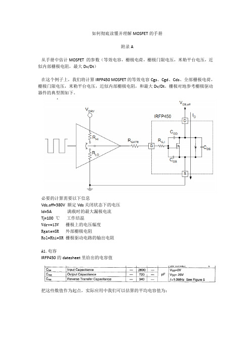
如何彻底读懂并理解MOSFET的手册附录A从手册中估计MOSFET 的参数(等效电容,栅极电荷,栅极门限电压,米勒平台电压,近似内部栅极电阻,最大Dv/Dt)在这个例子上,我们将计算IRFP450 MOSFET的等效电容Cgs、Cgd、Cds、全部栅极电荷,栅极门限电压,米勒平台电压,近似内部栅极电阻,和最大Dv/Dt。
栅极对地参考栅极驱动器件的典型图如下。
必要的计算需要以下信息Vds,off=380V 额定Vds关闭状态下的电压Id=5A 满载时的最大漏极电流Tj=100℃工作结温Vdrv=13V 栅极上的电压幅度Rgate=5R 外部栅极电阻Rol=Rhi=5R 栅极驱动电路的输出电阻A1.电容IRFP450的datesheet里给出的电容值把这些数值作为起点,实际应用中我们可以估算的平均电容值为:物理电容值可以从基本的关系式中获得:注意 Cgs是从手册的原始数值里得到的,在这个方程中,用同等测试条件下测得的电容值是很重要的。
同时记住Cgs是一个常量和电压无关。
另一方面,Cgd、Cds具有很强的非线性且和电压有关。
他们的最大值分别在Vgd和Vgs接近于0或等于0处,且分别随着Vgd和Vgs的上升迅速下降。
A2.栅极电荷最坏情况下的栅极电荷值(在特别的情况下),由IRFP450的Datesheet给出不同的栅极电压幅度,能由下面的典型Total Gage Charge曲线修正。
由下面图中13V的gate-to-source 电压开始,找到对应的drain-to-source的电压曲线,然后从横轴读出Total Gage Charge的数值。
如果需要更粗确的值,不同的栅极电荷成员要分别决定。
只有在米勒平台级别修正过后,我们才能估计Gate-to-source charge的值从下面的图中。
Miller电荷能由A1中的Crss,ave 的值获得。
最后,over drive 电荷成员(从米勒平台到最终的电压)能由下面的图中估计出。
如何看懂芯片规格书

如何看懂芯片规格书芯片规格书是了解芯片的重要途径,但对于非专业人士来说,理解规格书内容可能会有些困难。
因此,本文将从几个方面介绍如何看懂芯片规格书。
第一步:阅读页眉和页脚芯片规格书的页眉和页脚通常包含重要信息,如芯片的型号、版本、生产批次等。
这些信息可用于检验芯片的真实性和品质。
此外,还应注意规格书的发布时间,以确保所测量的数据符合当前标准。
第二步:查看电气特性电气特性是芯片规格书中最为重要的部分之一,其中包括芯片的电压、电流等参数。
了解这些参数可以帮助人们确定芯片的功耗、性能及适用范围,从而更好地应用芯片。
因此,在查看电气特性时,应该注意各个参数的单位和范围,以确保对芯片的理解准确无误。
第三步:查阅机械特性机械特性主要包括芯片的尺寸、重量和安装方式等。
这些特性直接影响芯片的应用及安装,因此在芯片选型时,需要根据具体的应用场景来选择符合要求的芯片。
在查看机械特性时,应注意芯片的安装方式和安装步骤,避免错误操作造成设备故障。
第四步:了解环境特性和可靠性环境特性和可靠性是芯片规格书中必须要注意的部分,它们直接关系到芯片的使用寿命和可靠性。
在了解这些特性时,应该重点关注芯片在高温、低温、潮湿、振动等极端环境下的性能表现。
此外,在了解芯片可靠性方面,还需要了解芯片的失效率、故障情况和寿命等,以便在选择芯片时可以做出正确的决策。
综上所述,看懂芯片规格书需要注意以上几个方面,包括电气特性、机械特性、环境特性和可靠性。
只有理解清楚这些内容,才能选择适合的芯片,并保证芯片在应用过程中的稳定性和可靠性。
Bioconductor基因芯片数据分析系列(一):数据的读取
Bioconductor基因芯片数据分析系列(一):R包中数据的读取R软件的Bioconductor包是分析芯片数据的神器,今天小编打算推出芯片数据的系列教程。
首先讲数据读取,以CLL数据包中的数据为例。
打开R studio。
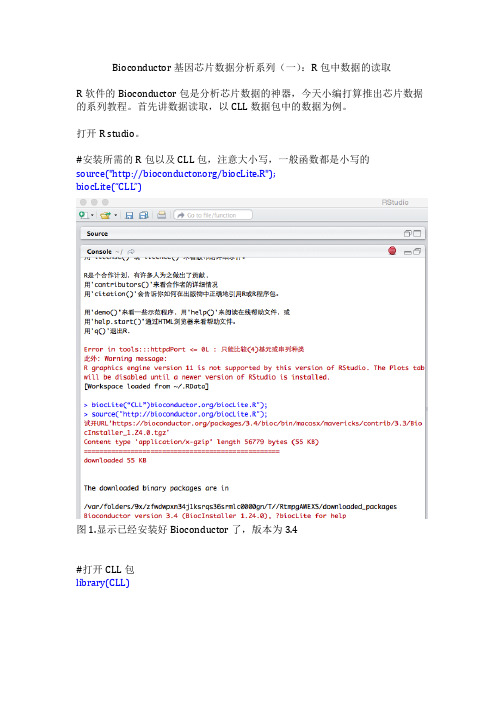
#安装所需的R包以及CLL包,注意大小写,一般函数都是小写的source("/biocLite.R");biocLite(“CLL”)图1.显示已经安装好Bioconductor了,版本为3.4#打开CLL包library(CLL)图2.显示打开CLL成功图3.右侧栏内可见看到目前载入的程序包data(CLLbatch)#调用RMA算法对数据预处理CLLrma<-rma(CLLbatch)#读取处理后所有样品的基因表达值e<- exprs(CLLrma)#查看数据e我们可以看到,CLL数据集中共有24个样品(CLL10.CEL, CLL11.CEL, CLL12.CEL, 等),此数据集的病人分为两组:稳定组和进展组,采用的设计为两组之间的对照试验(Control Test)。
从上面的结果可知,Bioconductor具有强大的数据预处理能力和调用能力,仅仅用了6行代码就完成了数据的读取及预处理。
Bioconductor基因芯片数据分析系列(二):GEO下载数据CEL的读取首先得下载一个数据,读取GEO的CEL文件采用如下命令:登陆pubmed,找到一个你感兴趣的数据库在底下栏目下载CEL文件打开R软件#安装所需的R包以及CLL包,注意大小写,一般函数都是小写的source("/biocLite.R");biocLite(“CLL”)>library(affy)>affybatch<- ReadAffy(celfile.path = "GSE36376_RAW")请注意目录的路径,在window下,反斜杠‘\’要用转义字符“\\”表示。
阅读英文数据手册总是很难?五招教你轻松搞定!

阅读英文数据手册总是很难?五招教你轻松搞定!阅读数据手册是一个工程师的必备技能,拿到一份数据手册,特别是英文数据手册,如何去读,才能更快更好的找到自己想要的东西?坚信:阅读英文手册,并没有想象的那么难不管什么芯片手册,都只是使用说明书而已。
而说明书一个最显著的特点就是必须尽可能地使用通俗易懂的语句,向使用者交代清楚该产品的特点、功能以及使用方法。
运用在大学里所学到的那些英文知识去分析这些手册,足矣。
数据手册的阅读难点:•语言风格——句子和句子之间经常会有跳跃,从一个意思到另外一个意思的过渡,有时候也作得不好。
比如说没有太大联系的两句话,就很有可能就被放在了一起。
•长句较多——数据手册通常喜欢采用一些长句对问题进行描述,并且这些长句所描述问题的通常都比较关键。
可以按主谓宾状补结构,把整个长句拆开,然后对每一个小短句进行分析,最后联系上下文,揣摩出整句的意思。
•专业词汇较多——只能靠平时的积累,并要善于借助网络资源。
注意:没有必要把每一个单词的意思都准确无误地翻译出来,只要理解它所表达的意思就足够了。
产品数据手册( Operating Manual ) 又称为“产品说明书” ( Instruction, Direction, Description ),是厂商为销售其产品而附的一种销售小册子,主要是用来告诫客户如何正确使用所购物品,以免因使用不当而造成不良后果。
各类产品的性能及用途是不相同的,因此各种产品说明书的说明方法及内容也各不相同。
说明书的正文究竟包含哪几部分,应根据不同产品的具体情况来确定。
(1)Release Date: 检查手册发布的日期,是预备版还是修正版;(2)General Description:一般性描述,但有时也会给出一些其他资料中没有提及的特性或用法;(3)Feature:提供常规特性信息,确认电器特性所在的条件以及特殊情况;(4)Application:通常简洁的告诉你该器件是否在你的应用领域;(5)Schematic Diagram:等效原理图;(6)Connection Diagram:引脚封装图;(7)Ordering Information:分类信息,可以找到带有完整零件编号的该期间的每个变种的列表,包括封装信息等;(8)Absolute Maxium Ratings:给出极限范围;(9)Electrical Characteristics:给出电气规范;(10)Typical Performance Characteristics:给出一些特性曲线;(11)Applications Information:给出示例电路和使用注意。
nordic52840英文数据手册

nordic52840英文数据手册摘要:1.引言2.nordic52840 英文数据手册的概述3.手册的主要内容4.手册在实际应用中的优势和局限5.结论正文:1.引言随着科技的飞速发展,越来越多的英文数据手册应运而生,为广大工程师和技术人员提供了便利。
nordic52840 英文数据手册就是其中一份备受关注的资料。
本文将对这份手册进行详细介绍,并分析其在实际应用中的作用。
2.nordic52840 英文数据手册的概述ordic52840 英文数据手册是一份详细介绍nordic52840 芯片的英文资料。
手册内容丰富,涵盖了芯片的硬件设计、软件编程、通信协议等多个方面。
通过阅读这份手册,用户可以全面了解nordic52840 芯片的功能、性能以及应用场景。
3.手册的主要内容ordic52840 英文数据手册主要包括以下几个部分:(1)芯片概述:介绍nordic52840 芯片的基本信息、性能参数以及应用领域。
(2)硬件设计:详细描述了芯片的引脚分配、内部结构、工作原理等内容,为硬件工程师提供了设计参考。
(3)软件编程:包括芯片的指令集、存储器映射、编程模型等方面的内容,为软件工程师提供了编程指南。
(4)通信协议:介绍了芯片支持的通信协议,如I2C、SPI、UART 等,以及相关的操作流程和数据格式。
(5)应用实例:提供了一些典型的应用实例,帮助用户了解如何在实际项目中使用nordic52840 芯片。
4.手册在实际应用中的优势和局限ordic52840 英文数据手册在实际应用中具有很高的参考价值,可以帮助工程师和技术人员快速熟悉芯片的性能和操作方法。
然而,手册也存在一定的局限性,比如部分内容可能过于专业,对于初学者来说难以理解。
此外,由于手册更新周期较长,可能无法及时反映芯片的最新特性。
5.结论总之,nordic52840 英文数据手册是一份实用性很强的参考资料。
通过阅读手册,用户可以全面了解nordic52840 芯片的性能和应用方法。
PCB设计教程3-如何从几十页的英文数据手册中快速提取重要信息?

PCB设计教程3-如何从几十页的英文数据手册中快速提取重要信息?PCB设计中非常有挑战但又跳不过去的一个坎就是根据元器件的数据手册进行建库(原理图符号库和PCB封装库)、重要信号的外围元器件布局以及布线,不幸的是99%的可能性- 你用到的元器件只有英文的数据手册,而且还是上百页,如何高效地阅读英文数据手册并能够在很短的时间内迅速提取与设计相关的重要信息是非常重要而且是必备的技能。
1. 一定要阅读英文、正确版本的数据手册有的工程师说- 我有翻译工具可以将数据手册翻译成中文。
听我的 - 最好用英语看原汁原味的资料,原因有三:1.你能相信翻译工具的准确性么?这可容不得一丝的错误。
我个人的体会,即便是经验丰富的工程师翻译过来的文章,读起来都不如原汁原味的英文好理解,何况机器翻译呢?即便采用了现在牛x哄哄的AI技术,能够达到95%的准确率已经是谢天谢地了,那5%的不准确性会让你吃尽苦头;2.你能确保将来任何时候都能用翻译工具解决你的阅读问题么?就像你已经习惯了戴眼镜,有的时候正好找不到眼镜,你就瞎了。
如果你要成为一个优秀的工程师,尤其还期望在企业里不断上升,阅读英文文献是你必须要跨过去的一道坎;3.其实根本不难,你阅读上十几篇数据手册就会发现这玩意很容易- 专业词汇就那么几个,语法就跟八股一样,很容易举一反三。
这么容易的事情没有退缩的理由,勇敢滴克服吧。
假设你愿意挑战自己,坚持用英语来阅读,下一步你要掌握的就是如何在最短的时间内从几十页甚至上百页的数据手册中把你需要的关键信息迅速定位提取出来,就如你从新东方学到的考托福的技巧一样,即便读不懂,也知道如何答题。
2. 英文数据手册的重要组成厂商的器件手册可能更新过多次,首先要确保你用的数据手册是官方的最终版本,且和你用的元器件相对应。
有些不良的数据手册网站,不知从哪里爬的信息,把几年前有错误的PDF数据手册文件也收录了,工程师用的时候没有注意,导致设计中出现了错误,因此一定要到厂商的官网去下载最后版本的数据手册,或者到Datasheet5网站上查询下载。
4个阅读英文素材的小技巧整理

4个阅读英文素材的小技巧整理4个阅读英文素材的小技巧英语的阅读是学习英语重要的一部分,但很多同学都觉得阅读很难。
下面是我整理的一些阅读英文素材的小技巧可以使你通过使用在母语中用到的技巧关心你提高阅读。
Tip 1: Read for Gist建议一:读主旨Gist = the main ideasGist = 主旨,要点Read the text a first time. Dont stop. Read to understand the main ideas, and dont look up new words. Youll be surprised that you can usually understand the general idea of the story.首先通读全文。
不要中途停下,在阅读的过程中理解主旨,不要查新词。
你会惊异地发觉,你总是能够理解故事的大意。
Tip 2: Use Context建议二:读上下文Context refers words and situations that are around a word you dont understand. Look at the example sentence:上下文指的是围绕一个你不理解地词语地一些词组和语境。
请看例句:I went to the shlumping to buy some chitla for dinner.Whats schlumping? - it must be a store because you bought something there.Shlumping是什么意思?——它确定指的是一个商店,由于你是在那儿买东西。
Whats chitia? - It must be food because you are going to eat it for dinner.Chitia是什么意思?它确定是一种食物,由于你晚餐得吃它。
- 1、下载文档前请自行甄别文档内容的完整性,平台不提供额外的编辑、内容补充、找答案等附加服务。
- 2、"仅部分预览"的文档,不可在线预览部分如存在完整性等问题,可反馈申请退款(可完整预览的文档不适用该条件!)。
- 3、如文档侵犯您的权益,请联系客服反馈,我们会尽快为您处理(人工客服工作时间:9:00-18:30)。
如何阅读英文的芯片数据手册
EMAIL:ql_smbj@
Q Q : 20761258
2009-03-31
申明:为方便计,本文将以AD9945为例,进行描述!
我们坚信,阅读英文芯片手册,并没有想象的那么难
不管什么芯片手册,它再怎么写得天花乱坠,本质也只是芯片的使用说明书而已。
而说明书一个最显著的特点就是必须尽可能地使用通俗易懂的语句,向使用者交代清楚该产品的特点、功能以及使用方法。
从这个角度看,无论什么芯片手册,都不会存在特别偏僻的语法、生僻的单词(当然专业词汇除外),运用在大学里所学到的那些英文知识去分析这些手册,足矣。
俺个人觉得,这些数据手册的阅读难点主要有如下三点:
语言风格——跟平常我们所阅读的新闻、报导都不一样,好多数据手册在表达意思上的连贯性做得不是很好,并且从一个意思到另外一个意思的过渡,有时候也作得不好,套句老话,就是乘得不好,转得过硬。
比如说没有太大联系的两句话,就很有可能就被放在了一起,按照俺们的习惯思维,挨这么近的两句话,肯定会有联系,可这数据手册的描述却偏偏不然,它就没联系,它就放一起,没办法,只得接受(莫非这也是中外思维的差异?)。
长句太多——为保证严谨,不至于让读者产生误解,数据手册通常喜欢采用一些长句对问题进行描述,并且这些长句所描述问题的通常都比较关键。
这很让人头疼,要连贯地理解这些长句,需要俺们有比较好的记忆力。
当然,俺们也有笨办法:按照古老的主谓宾状补结构,把整个长句拆开,然后对每一个小短句进行分析,最后联系上下文,揣摩出整句的意思。
专业词汇太多,甚至会出现一些字典上都找不到的单词,——这没办法,一得靠平时的积累,二得善于借助网络资源,比如CNKI翻译助手(/)就是个挺专业的网站。
强调一下:俺们没有必要把每一个单词的意思都完完全全地、准确无误地翻译出来,只要理解它所表达的意思就足够了,古人云:不可言传、只可意会,放到这,也合适。
俺们可以这么去阅读一个芯片的数据手册
9先看看芯片的特性(Features)、应用场合(Applications)以及内部框图。
这有助于我们对芯片有一个宏观的了解,此时需要弄清楚该芯片的一些比较特
殊的功能,充分利用芯片的特殊功能,对整体电路的设计,将会有极大的好处。
比如AD9945可以实现相关双采样(CDS),这可以简化后续信号调理电路,并且抵抗噪声的效果还好。
9重点关注芯片的参数,同时可以参考手册给出的一些参数图(如AD9945的TPC 1,TPC2等),这是俺们是否采用该芯片的重要依据。
像AD9945,就可以关注采样率(maximum clock rate)、数据位数(AD converter)、功耗(power consumption)、可调增益范围(gain range)等。
9选定器件后,研究芯片管脚定义、推荐的PCB layout,这些都是在硬件设计过程中必须掌握的。
所有管脚中,要特别留意控制信号引脚或者特殊信号引脚,这是将来用好该芯片的前提。
比如AD9945的SHP、SHD、PBLK、CLPOB 等。
9认真研读芯片内部寄存器,对寄存器的理解程度,直接决定了你对该芯片的掌握程度。
比如AD9945就有4个寄存器:Operation、Control、Clamp Level 和VGA gain,对于这些寄存器,必须清楚它们上电后的初始值、所能实现的功能、每个bit所代表的含义这些基本情况。
9仔细研究手册给出的时序图,这是对芯片进行正确操作的关键。
单个信号的周期、上升时间、下降时间、建立时间、保持时间,以及信号之间的相位关系,所有这些都必须研究透彻。
像AD9945的Figure 8 和 Figure 9 就很值得花费时间去仔细研究。
提醒
凡是芯片数据手册中的“note”,都必须仔细阅读,一般这都是能否正确使用、或能否把芯片用好的关键之所在。
只是很简单的一些个人心得,期盼能有达人,加以补充。
