XSS-1000吸气式探测器设计使用手册
吸气式感烟探测器缺陷分析及处理方案的研究[精品资料]
![吸气式感烟探测器缺陷分析及处理方案的研究[精品资料]](https://img.taocdn.com/s3/m/686b715e6529647d26285231.png)
吸气式感烟探测器缺陷分析及处理方案的研究[精品资料] 吸气式感烟探测器缺陷分析及处理方案的研究-精品资料本文档格式为WORD,感谢你的阅读。
摘要:吸气式感烟探测器误报率高是方家山核电工程项目JDT系统调试过程中较为突出的问题。
本文对这两个问题进行了分析并研究了相应处理方案,提出通过取样孔变径、取样管路变更、控制设备安装及运行环境、防止减少沉积物脱落等方法来降低吸气式感烟探测器误报率。
关键词:ASD ;灵敏度;取样管路;取样孔;沉积物。
K826.16 A)肩负着对方方家山全厂火灾报警控制系统(JDT系统家山核电工程各厂房及设备的火灾监测任务,并在火警时发出火警信号及联动控制信号。
JDT系统是方家山各厂房、设备投运的先决条件,是方家山机组调试、运行期间一道重要的安全屏障。
在JDT系统调试过程中发现的问题包括系统设计、设备质量、安装质量等,例如:JDT系统逻辑关系表设计不合理、消防联动设备需JDT系统控制机柜提供DC24V电源、控制机柜多处报联动设备反馈、感温电缆安装时间的选择、控制机柜运行不稳定等。
本文将结合JDT系统调试现场的实际情况,针对吸气式感烟探测器误报率高以及JDT系统与消防联动设备设计上存在缺陷这两个问题进行系统、全面的分析,并提出合理且行之有效的解决方案。
吸气式火灾报警探测器误报率高的分析及解决方案2.1 吸气式火灾报警探测器(以下称ASD)概况ASD是一种具有报警功能及继电器信号输出的空气管路取样式感烟火灾探测器,利用高灵敏度的烟雾探测器对重要厂房、设备作出火灾早期预警,也可对需要高灵敏度烟雾探测的场所及高洁净、高大空间、高温、高湿或具有强电磁辐射等环境进行火警监测。
JDT系统监视模块对ASD火警继电器和故障继电器触点的状态进行监视,并将信息通过双总线传输至JDT控制机柜,从而实现ASD与JDT系统控制机柜通讯。
一般情况下JDT系统控制机柜向ASD提供DC24V电源,特殊情况(JDT系统控制机柜DC24V电源负载过重)下会专门为ASD设置DC24V电源装置。
吸气式探测系统学习(规范、原则)
吸气式探测系统学习问题:1、采样孔的保护面积?答:根据空气流速不同可分为两种低空气流速时可按传统点型感烟探头布置,如果需要达到增强型灵敏度和高灵敏度泽需依次减少。
高空气流速(空气流速大于1米/秒)当采样孔在高气流环境(探测区域空气交换率>8.6次/h )下布置时,每个采样孔的保护面积应相应缩小。
对于回风采样方式,每个采样孔的最大保护面积不宜超过0.36m22、采样孔的设置位置?答:★采样孔至墙壁、梁边的水平距离,不应小于0.5m;★采样孔周围0.5m内,不应有遮挡物;★采样孔至空调送风口边的水平距离,不应小于1m;至多孔送风顶棚口的水平距离,不应小于0.3m;★在走道的顶棚上设置采样孔时,宜居中布置。
采样管末端帽距端墙的距离,不应大于采样孔安装间距的一半;★当梁突出顶棚的高度超过600mm时,每个梁间区域至少应设置一个采样孔,当梁突出顶棚的高度小于200mm时,可不计梁的影响;★当梁高在200mm至600mm之间时,每个梁间区域的采样孔设置应符合现行国家标准《火灾自动报警系统施工及验收规范》GB50166的相关规定。
3、HSSD能否存储信息?能存多少?掉电后是否消失?能存200,4、采样管弯头曲率的要求?采样管弯头弧度应大于90°,曲率半径应在40mm至200mm之间。
不得强行扭曲采样管来改变管道的方向。
(一般为70mm)5、报警原理激光散射体探测法,即:采样的空气持续流入一个装有高能光源的探测室,这一光源会被样品中的任何烟雾颗粒散射,散射光由一个固态光接收器进行分析。
散射光的量与烟浓度成正比。
光散射系统对阴燃火和电线过载造成的烟雾颗粒很敏感,因此对于要求早期报警的地方很有用。
但这种探测器会受灰尘干扰,因此多数探测器会安装复杂的过滤网或电子除尘装置。
6、联网方式及所需设备GST空气采样式感烟火灾探测报警器本身都具有RS485通讯端口,通过两芯屏蔽电缆可以方便地将一台以上的GST 空气采样式感烟火灾探测报警器连接成网络,两台设备之间最大距离可达1200米,整个网络只需一个编程器,就可对网中的所有设备进行设置;另外,还可使用GST空气采样式感烟火灾探测报警器专用的联网监控软件,通过一台计算机实时管理、监测全部设备的运行情况。
极早期空气采样品牌型号统计

53546-022APO XP95风道探测器 (1) BK711 空气采样式烟雾探测器单管数字显示联网型 (2) BK721 空气采样式烟雾探测器单管LCD显示联网型 (3) BK714 空气采样式烟雾探测器四管数字显示不分路联网型 (4) BK724 空气采样式烟雾探测器四管数字显示分路联网型 (5) BK734 空气采样式烟雾探测器四路可编程LCD显示不分管联网型 (6) BK754 空气采样式烟雾探测器四管可编程LCD显示分路联网型 (7) Xtralis ICAM IFT-1 极早期空气采样探测器 (1) Cirrus Pro100 空气采样烟雾探测器 (2) Cirrus Pro100 空气采样烟雾探测器 (3) Cirrus Pro200D 空气采样烟雾探测器 (4) Cirrus Pro200DSC 空气采样烟雾探测器 (5) Cirrus Pro200 + 空气采样烟雾探测器 (6) Cirrus Pro200D + 空气采样烟雾探测器 (7) Cirrus Pro200DSC + 空气采样烟雾探测器 (8) Cirrus ProRDP 空气采样烟雾探测器 K183空气采样探测器探测单元(标准灵敏度)
极早期空气采样品牌型号统计
类别
一、空气采样烟雾探测器
品牌
凯德Kidde
爱森司
科达士GO-DEX
威士达Vesda
ICAM
Securiton
Securiton
瓦格纳WAGNER
盛赛பைடு நூலகம் 海湾
艾华AVA
福莫斯特FMST
阿波罗APO
博康
IFD
利达华信 二、空气采样探测器附件 凯德Kidde
科达士GO-DEX
(3) K191 空气采样探测器联网模块(含MODE) (1) AADUCTKIT光电风管感烟探测器组 (2) DNR光电风管感烟探测器 (3) DNRW防水光电风管感烟探测器
XSS-1000吸气式探测器设计使用手册
Sensitivity Test/
灵敏度测试
Normal/正常 Normal/正常 Normal/正常 Enhanced/增强 Enhanced/增强
High/高
System Sensitivity/
系统灵敏度
Normal/正常 Enhanced/增强
High/高 Enhanced/增强
4
I56-1000-01C
图一 通风管路安装方式 3.1.2 常规环境管路设置
此时系统通常将采样点按传统点式探测器布置的位置来布置。如果需要达到增强型灵敏度或者高灵敏度,每个探测点的常 规保护面积需进一步减少:
因为烟雾需要热量才能上升到一定高度,如果火势非常小,那么只有最小范围的烟雾能到达高空。考虑到这些,必须以高 于普通区域的标准来测试系统,下表详细说明了吸气式烟雾探测系统的推荐测试方法及高度限制:
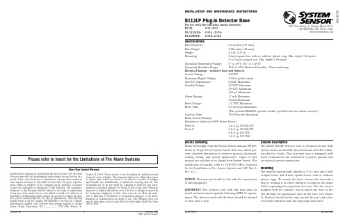
该探测器还具有故障自诊断能力,当空气采样管发生堵塞、破损;风机发生故障;系统出现问题等,探测器会给出相 应的故障信息。
2 系统组成
该系统由如下设备组成,根据现场需要还可以进行增加或减少。 • 吸气式探测器; • 专用电源箱; • 吸气管路; • 配接的火灾报警控制器(可选配); • 可配接的显示、控制设备(如声光显示等,可选配)。
如果少于 10%的被保护区域超出了上表天花板高度限制,可以参考<10%一栏的数据。如果是“人”字坡顶,那么可以参 考快速反应栏的数据。
Ceiling Areas ﹤10% of main area/ 少于 10%的被保护区域内的天花板
高度
General/ Rapid Attendance/
一般情况 12.50m 14.00m 18.00m 9.00m 12.50m 5.00m
DIONEX-ICS-1000操作指南
DIONEX ICS-1000使用操作指南一、注意事项1. 样品必须进行预处理。
2. 作校准曲线和测定样品应在相同条件下进行,保证测定结果的可靠性。
3. 因试剂、器皿或者样品的预处理可能引入污染干扰测定,因此要特别注意防止污染。
4. 每次测定前必须进行排气泡的过程。
只有在排气泡时,才可以点击“PumpSetting”的“Prime”。
5. 在关闭废液阀时,不能用力过猛,避免损坏阀体。
6. 只有在发现有液体从抑制器废液管流出时,才能设置抑制器电流。
7. 注意观察泵的压力值。
阴离子测试时,正常压力值为1600Psi,当发现压力值异常偏高时,如陡然增加1000Psi,应立即点击“Shutdown ”,并告知管理人员。
8. 测试完成后,必须让仪器继续运行20min以上。
同时,用高纯水冲洗定量环和注射器3次以上。
9. 当仪器报警时,立即点击“Shutdown ”,并告知管理人员。
二、阴离子测定步骤1. 准备好淋洗液、标准样品、待测样品、高纯水等。
2. 打开氮气瓶阀门,调整氮气瓶出口处压力在0.2MPa以内,调整淋洗液瓶前的压力在5~6PSi。
3. 先开离子色谱仪电源,再开电脑电源。
若先开电脑,再开色谱仪电源,注意勾选“connected”。
4. 点击“Chromeleon”快捷图标,进入操作界面。
5. 逆时针扭动2~3圈,打开“废液阀”。
点击“pump setting”,点击“Prime”开泵,排气泡2~3min。
然后点击“Off”停泵。
顺时针扭动2~3圈关闭“废液阀”。
点击“On”正常开泵。
同时观察仪器是否有泄漏现象。
6. 当发现有液体从抑制器废液管流出时,点击“Detector setting”,在“Suppressortype”内选择“ASRS-4mm”,点击“Close”;点击鼠标右键,输入淋洗液浓度,设置抑制器电流。
7. 开始采集基线。
在采集基线的过程中,编制样品表。
8. 基线平稳后,停止采集基线,点蓝点。
LDS1000_使用说明书

目录1 一般信息1-1 1.1 本手册使用符号1-1 1.1.1 安全符号1-1 1.1.2 指示符1-2 1.1.3 真空符号1-2 1.1.4 术语定义1-3 1.2 INFICON服务的支持1-5 1.2.1 维修中心1-6 1.3 前言1-7 1.3.1 用途1-7 1.3.2 技术参数1-8 1.3.2.1 物理参数1-8 1.3.2.2 电气参数1-8 1.3.2.3 接口1-8 1.3.2.4 其它参数1-9 1.3.2.5 环境条件1-9 1.4 开箱1-9 1.4.1 设备供货范围1-101.4.2 附件与选件1-102 安装2-1 2.1 运输2-1 2.2 就位2-1 2.3 仪器组件2-1 2.3.1 电子学模件2-3 2.3.1.1 通风2-3 2.3.1.2 键操作开关2-3 2.3.1.3 工作和显示单元2-3 2.3.2 质谱仪模件2-6 2.3.2.1 涡轮分子泵2-7 2.3.2.2 质谱仪2-8 2.3.2.3 离子源2-9 2.3.2.4 分离系统2-9 2.3.2.5 离子收集极2-9 2.3.2.6 静电放大器2-9 2.4 安装2-10 2.4.1 真空连接件2-11 2.4.2 电气连接件2-12 2.4.3 连接质谱仪- 电子学模件2-13 2.4.4 设定工作模式2-15 2.4.4.1 调整配线器2-16 2.4.5 连接至外控制器2-16 2.4.5.1 连接至SPS 2-17 2.4.5.2 数字I/O 插头, 多功能(16-脚) 2-18 2.4.5.3 数字输出, 插头: 数字输出(16-脚) 2-182.4.5.6 模拟输出2-19 2.4.5.7 图形记录仪输出, 模拟输出插头(4脚) 2-20 2.4.5.8 音响输出2-21 2.5 仪器运行2-22 2.5.1 功能说明2-22 2.5.2 连接选件2-23 2.5.2.1 逆流配置(GROSS) 带泵模件2-24 2.5.2.2 逆流配置(FINE) 不带泵模件2-25 2.5.2.3 中间进气口配置(FINE) 2-262.5.2.4 吸入器模式配置2-273 运行3-1 3.1 仪器接通电源3-1 3.1.1 校准压强规管3-2 3.1.2 确定真空模式的机器因素3-2 3.2 操作单元上的控制器3-3 3.2.1 操作与显示单元3-3 3.2.1.1 全貌3-3 3.2.1.2 操作单元上的控制器3-3 3.2.1.3 显示元件3-5 3.2.1.4 配置仪器参数3-6 3.2.1.5 菜单功能3-7 3.2.2 电源开关3-11 3.2.3 键开关3-11 3.3 校准3-12 3.3.1 内部校准3-12 3.3.2 外校准3-14 3.3.2.1 真空和吸入器模式的标准校准3-14 3.3.2.2 动态校准3-14 3.4 可编程的控制通讯3-16 3.4.1 数字输入3-16 3.4.2 继电器输出3-17 3.5 音响讯号3-183.6 停机3-184 维护4-1 4.1 INFICON服务4-1 4.2 维护工作4-1 4.2.1 更换过滤插件4-2 4.2.2 测试真空计PSG400 4-2 4.2.3 泵模件选件的维护4-2 4.2.4 更换电源保险丝4-3 4.2.5 清洗4-3 4.3 维护计划4-3 4.4 警告和误差信息4-6 4.4.1 硬件问题4-6 4.4.2 与应用有关的问题4-10附录A-1 A 索引A-11一般信息亲爱的用户,您选购的检漏仪是INFICON公司在真空与检漏技术领域积累了多年经验的产品.LDS1000 检漏仪尤其适合于组装在工业系统中. 它的多功能性, 操作简易和接口提供使这台设备适用于广泛的应用范围.本使用说明书包含有关LDS1000的功能, 安装, 启用与操作等重要说明.注我们建议您仔细阅读本使用说明书, 以保证从一开始就进入最佳工作状态.一般说明本公司保留设计与特定参数的更改权. 图示是无约束的.1.1 本手册使用符号1.1.1 安全符号有关操作安全与保护的重要标注如下:有关正确安装与使用设备的信息. 忽视将导致误动作或设备的局部损伤.有关防止大范围地损坏设备和环境的信息.有关防止各种人身伤害的信息.表示必须由熟练人员才能执行的步骤.1.1.2 指示符提示有关有益的步骤信息.注有关用户必须遵守的特殊技术要求的信息.参考图示依次包含章节数, 图号和项号. 例如: 图2-4/7为2章的图4中项7.1.1.3 真空符号下面列出本手册中使用的某些重要真空符号.图1-1 真空符号1.1.4 术语定义质量调整这个功能自动调谐质谱仪, 显示最大漏率. 控制处理器在选择的范围内改变离子加速电压直到离子检测器检测到最大的离子流. 在每次校准过程中自动运行质量调整功能.自动测量量程自动选择前置放大器的放大量程.LDS1000的自动测量量程功能覆盖所选定模式: 真空模式或吸入器模式的整个测量量程或漏率量程.自动抑零扣除和更新氦本底. 这个模式是用于确定漏率讯号的内部本底, 以便在随后的测量中不再出现这个内部氦本底.每次从STBY 转换至MEAS 或调用CAL 模式时执行. Zero 测量仅运行于前置放大器最灵敏的量程, 对于其它测量量程进行计算. 对不同测量量程确定的零值贮存在内存中, 在以后校正全部漏率时使用.如以后的校正结果中出现负值, 贮存的偏离值将按最小值为零值的原则变更. 从而校正值将自动适应衰减的本底(自动本底修正).GROSSGROSS是允许高的进气口压强(3 毫巴) 的测量模式. 最小可检漏率为3.5 x 10⁻¹⁰毫巴升/秒.FINEFINE 是进气口压强低于0,3 毫巴的中等测量模式. 检测上限为5 x 10-11毫巴升/秒.前级压强涡轮分子泵与涡旋泵之间前级管道中的压强.内部氦本底在测量系统中当前的氦分压强. 内部氦本底值是在Stand-by 模式中测量的, 并在转换至测量模式后, 最后从测量的讯号中扣除.最小可检漏率LDS1000可检测的最小漏率(≤5 x 10-11毫巴升/秒).菜单用户可使用菜单按自己的要求编程LDS1000. 菜单是树状的分支结构.测量测量模式LDS1000 测量试样的漏率.交货状态/ 缺省LDS1000 出厂时的交货状态.待用(STBY)等待状态. LDS1000 显示内部氦本底.PLC程序控制系统(可由用户编程). 生产设施的控制系统, 也控制LDS1000.1.2 INFICON服务的支持如将设备返回INFICON或INFICON的授权代理. 请标明设备无危害健康的物质或设备已污染. 如已污染, 前请标明危害的性质. 无污染申报表的任何设备INFICON将按发送地址退回. 对于LDS1000的单个元件同样有效.详细说明污染类型的表格见本章末.建议签订一份维护和检修合同.1.2.1 维修中心当您需要紧急协助时, 请与当地INFICON维修中心联系或联系德国科隆的服务热线:1.3 前言1.3.1用途LDS1000 是一台氦检漏仪用于安装在试漏系统中. 通常由PLC或RS232控制.LDS1000是检漏模件用于组装在工业试漏系统中. 可用于定量确定试件中的漏孔.•如在试件中充以氦压, 置于用真空连接至LDS1000的测试室中, 或•在试件中充以正压的氦测试气体, 用吸入器探头在试件外搜索(吸入器模式).LDS1000只能用于检漏.切勿用作抽气系统(尤其不能抽腐蚀性或潮湿气体).LDS1000的质谱仪模件中有强的永久磁铁可影响医疗注入或电子学设备.1.3.2 技术参数1.3.2.1 物理参数最大进气口压强GROSS 3毫巴最大进气口压强FINE 0.3毫巴最低可检氦漏率•真空模式–GROSS 模式≥3,5x10⁻¹⁰毫巴⋅升/秒–FINE 模式≥5x10-11毫巴⋅升/秒• 吸入器模式≥1×10⁻⁷毫巴⋅升/秒可显示的最大氦漏率0.1毫巴⋅升/秒测量范围10个量级漏率讯号的时间常数<1秒(盲住, 最终值的63%)可检质量数2,3和4质谱仪180°扇形磁场离子源两个阴极;铱/氧化钇进气口DN25KF起转时间(从开机) ≤3分1.3.2.2 电气参数电源, 可开关, 单相(与型号有关) 115伏±15%230伏±15%电源频率50/60 Hz功率损耗<120伏安保护类型–电子学模件IP30–手持单元IP54电源电缆(EU,USA,UK) 2.5米1.3.2.3 接口记录仪输出0-10伏控制输出典型24伏,最大35伏接口RS232音响输出1.3.2.4 其它参数电磁阀24伏电子学模件尺寸483 × 133 × 375毫米19 x 5 x 15’’质谱仪模件尺寸360 x 212 x 227毫米14,2 x 8,3 x 8,9’’电子学模件重量10公斤22磅质谱仪模件重量8,5公斤20磅污染水平(按IEC60664-1标准) 2过电压类别(按IEC60664-1标准) Ⅱ1.3.2.5 环境条件用于室内允许环境温度(在运行过程中) +10 °C … +40 °C允许储存温度–20 °C … +60 °C最高相对湿度80% 无凝聚最大允许海拔高度(在运行过程中) 2000米质谱仪的最大允许磁场感应强度7mT1.4 开箱LDS1000到货后应立即开箱, 即使暂不安装.检查运输箱是否有任何外伤. 完全取开包装材料.检查LDS1000的完整性(参阅1.4.1节), 并仔细目测检查LDS1000.如发现任何损伤, 立即报告代理商和保险商. 如损坏件必须更换, 请与订货部门联系.提示保留包装材料, 以便发现损坏时申诉.1.4.1 设备供货范围LDS1000 基本单元, 包括: 件号. 146 00• 电子学模件• 质谱仪模件, 真空计, 2 套钥匙• 3 根电源电缆(Europ, USA, UK)• SPS 连接件• 记录仪的连接件插头• 成套保险丝LDS1000基本单元: 件号. 146 01与146 00相同(见上), 但予装配电子学模件与质谱仪模件之间10 米间距(LDS包括改进的电路板和10 米连接电缆)1.4.2 附件与选件下列部件可附加订货:吸入器阀门• 吸入器管线3米带LEDs和测试器5米带LEDs和测试器10米带LEDs和测试器件号. 145 20 件号. 145 21 件号. 145 22 件号. 145 23MS 电缆1,5米3米5米10米包含专用的MSV电路板件号. 146 31 件号. 146 32 件号. 146 33 件号. 146 34延伸电缆5米10米15米件号. 146 40 件号. 146 41 件号. 146 42内部测试漏孔TL7 件号. 145 49 泵模件D4B 230V 件号. 145 11 • 带软管的喷枪件号. 165 55污染申报表检修和/或服务的提供仅适用于已提交正确完整申报表的真空设备和元件. 手续不完整的将导致延迟.本申报表必须由经过授权和有资格的人员填写和签署.1产品说明型号编号出厂号2 返修原因3 使用的工作液体4 产品的污染过程:毒性否□是□腐蚀性否□是□生物危害性否□是□*)易爆性否□是□*)放射性否□是□*)其它有害性物质否□是□5 有害的物质、气体和/或副产品请列出与设备接触过的物质、气体和副产品:商标/ 产品名称制造厂化学名称(或符号)危险性材料等级如泄漏应采取的措施人体接触的急救方法6 有法律约束的申报:我申明本申报表中的信息是完整和正确的。
便携式VOCs气体检测仪HYS1000 1001 1002 1003操作手册说明书

操作使用手册便携式VOCs气体检测仪OPERATIONMANUAL系列HYS1000/1001/1002/1003使用前须知注意特别提示警告配置1、标准配置2、可选配置产品概述部件构成技术指标电池充电时钟电池仪器操作打开/关闭仪器开机后显示屏主界面显示内部数据界面功能选择界面校准功能a) 校准零点b) 校准量程c) 连续校准d) 校准周期测量功能a) 气体种类b) 气体单位c) 测量范围1112223346789101112121313141515161617171718191920202121222223232424252526272828282929323338d) 自定义CFe) 测量去除率查询功能a) 数据查询b) 报警查询c) 校准查询d) 数据清除e) 版本信息设定功能a) 报警设置b) 仪表设置时间设定泵速设定存储设定用户设定现场设定仪器标定报警信号数据采集与PC机进行数据传输内置采样泵外部过滤组件日常维护附录A(故障处理)附录B(气体因子详情种类)产品保修卡CONTENTS使用前须知USEFUL TIPS注 意ATTENTION任何人在对产品进行使用、维护、检修前必须先阅读本手册。
只有按厂家的指示使用、维护和检修,产品的运行才能达到设计要求。
用户应了解如何设定仪表参数,并理解所获检测数据的含义。
为防止电击危险,打开仪器盖前一定要关闭电源。
为维修取下传感器前,请断开电池与仪器的连接。
在开盖的情况下绝对禁止操作。
务必在确认无危险的区域打开仪器盖及取下传感器。
本公司生产的HYPERSENSE1000系列便携式VOC气体检测仪产品简称HYS1000系列,HYS1000款和HYS1002款均取得本质安全认证。
特别提示SPECIAL NOTES仪器首次开机,由于检测腔内可能会存有少量有机/无机气体,会导致仪器显示的示值浓度有数据,这属于仪器的正常现象。
首次开机可在不存在有机气体、有毒有害气体的场所打开本仪器,待检测腔内气体排空后,仪器示值浓度自动恢复为无有机气体、无有毒有害气体的零值状态。
空气采样式探测器说明书
任何时候勾上此功能都会开始“快速学习”。“快速学习”期间探测器前面的绿色正常指示灯会闪烁15分钟,完成后变为常亮。
注:“快速学习”之后还要经过24小时才能达到完全的灵敏度,除非启动“演示模式”(见第3.10节,“Demo mode”)。为保证探测器正常工作,不能将其放在“演示模式”中,而应使其完成24小时学习期。要取消“演示模式”,勾上此框或关闭电源并重新启动探测器。
编码总线接口板(APIC)端口(见第6.2.3节)(仅编码探测器有此接口板)
探测器编码DIP开关(见第7.2.1.1节)
2.2.2探测器接线端子
探测器接线端子示意图如图3所示:
图3探测器内部接线端子示意图
常闭故障继电器触点
常开火警继电器触点
总线接口,用于连接总线(见第6.2.3节)(仅编码探测器有此接口)
3.2报警阈值Alarm levels–Alarm Levels and delays tab,level subgroup(报警阈值和延时功能,级别功能)
在Level(级别)子菜单中的Fire1(1级火警),PreAlarm(预警)和Aux(辅助等级)功能中设置的值都是相对的柱状标度图,使得探测器正确地触发报警。Fire 2 level(2级火警)功能则以% obs/m为单位赋予火警2等级绝对报警阈值。Aux级别出厂默认设置为级别10,表示这一报警会在Fire后发生。PreAlarm和Fire1的默认设置分别为6和8。Fire 2的默认设置为20% obs/m。
火警:当达到报警等级且延时结束时亮。
故障:当探测器发生故障时亮。
正常:亮时表明探测器工作正常无故障。当探测器开始适应环境时,在15分钟的“学习期”内,“正常”指示灯闪亮。
JBF-AR10P1 吸气式感烟火灾探测器
吸气式感烟火灾探测器JBF-AR10P1使用说明书(使用产品前,请阅读使用说明书)目录1 概述 (1)1.1 产品特点 (1)1.2 主要用途及适用范围 (1)1.3 型号组成及代表意义 (2)1.4 使用环境条件 (2)2 工作原理 (2)3 性能参数 (2)4 安装调试 (3)4.1 外形及安装尺寸 (3)4.2 安装说明/步骤 (4)5 使用和操作 (4)5.1 产品主界面 (4)5.1.1状态指示灯 (5)5.1.2操作按键 (5)5.2 菜单界面流程及拓扑图 (6)5.3 弹出界面显示 (7)5.3.1开机界面 (7)5.3.2主界面 (7)5.3.3火警信息 (7)5.3.4故障信息 (7)5.3.5等待提示 (7)5.3.6权限登录 (7)5.4 菜单操作 (8)6 调试步骤 (12)7 故障分析与排除 (12)8 保养、维护 (13)9 运输、贮存 (13)9.1 运输 (13)9.2 贮存 (13)10 开箱及检查 (14)11 注意事项、免责声明 (14)JBF-AR10P1吸气式感烟火灾探测器使用说明书(使用产品前,请阅读使用说明书)1概述JBF-AR10P1吸气式感烟火灾探测器(也称为空气采样探测器或主动吸气式火灾探测器)是一种极早期烟雾探测的设备,能主动地采集探测区域内的空气样本并分析是否存在烟雾颗粒,进而判断是否有火灾发生。
1.1产品特点⚫采用先进光电感烟探测技术;⚫0.02~20% obs/m的高灵敏度探测范围;⚫液晶屏用户显示界面及简易直观的操作模式;⚫三路继电器触点,可配置为常开或常闭,辅助继电器支持多种自定义模式;⚫微尘分离技术既可提高误报免疫力又可延长过滤器使用寿命;⚫特殊设计的探测腔及材料,抗污染效果优良;⚫对外接口丰富,具备CAN、继电器及通用USB等接口;⚫快拆式结构,方便过滤器更换及产品保养;⚫具备动态调节的自适应模式;⚫具有10级预警和4级火灾报警级别;1.2主要用途及适用范围该产品主要用于超大空间、仓储中心、数据中心、古建及工业现场等难以探测、环境条件恶劣、需要隐蔽安装、维修困难等场所。
吸气式感烟火灾探测器系统操作手册

IFD Cirrus Pro极早期火警预警系统操作手册目录第一章一般操作 (1)第二章异常操作 (6)第三章查询 (9)第一節事件检视 (9)第二節历史曲线图 (11)第三節数据库查询 (12)第四節历史数据查询 (13)第五節图面打印 (14)第四章CirrusPro控制器操作 (15)第一節组件选项 (15)第二節灵敏度设定 (16)第三節编辑文字 (16)第四節输入输出设定 (17)第五節管之进气流 (18)第六節保修信息 (18)第七節制造信息 (19)第八節清除事件线图 (20)第九節展示模式 (20)第五章数据设定 (21)第一節树状窗口操作 (21)第一項监控计算机 (22)第二項F-NET (25)第三項区域 (30)第四項CPD(CirrusPro控制器) (33)第二節图片窗口操作 (36)第一項新增 (36)第二項删除 (36)第三項更改属性 (37)第四項CPD位置调整 (37)第六章登入 (39)第七章使用者管理 (40)第一節使用者权限 (40)第二節新增使用者 (41)第三節修改使用者 (41)第四節删除使用者 (42)第一章一般操作进入极早期火警预警系统, 屏幕显示如下:窗口说明:树状窗口极早期火警预警系统之数据为树状结构,以监控计算机图标开始,第二层为区域侦测网络(F-NET) ,每一个区域侦测网络包含区域(第三层),每一个区域包含极早期火警预警控制器(CPD) (最后一层)。
树状显示窗口如下: 图控树状窗口 图片窗口讯息窗口 CPD 状态窗口图示说明:监控计算机区域侦测网络(F-NET)区域极早期火警预警控制器(CPD)讯息窗口依CPD的状态显示该异常CPD之相关讯息。
图片窗口显示目前选定区域图片。
在树状窗口节点上按下鼠标左键, 即可快速切换至该区域或极早期火警预警控制器图片。
鼠标光标图标说明:鼠标游标在图面上移动时之图示。
当鼠标游标在图面时按下鼠标左键时之图标,此时移动鼠标可拖曳图面。
吸气式烟雾探测报警系统参数
吸气式烟雾探测报警系统参数1.系统构成▪吸气式烟雾探测报警系统是一个相对独立的子系统。
各个房间的吸气式烟雾探测报警器均需各自组成网络,在与现场火灾自动报警系统进行连接的同时还需与相应的综合监控系统进行连接。
▪吸气式烟雾探测报警系统由管路吸气感烟探测器、空气采样管路、附属设备及电源构成。
2.探测器2.1 功能要求▪探测器类型应为管路吸气式高灵敏型空气采样(吸气)式烟雾探测报警器。
▪探测器应采用激光作为探测光源,且激光探测腔应具有自清洁能力。
▪探测器应具备提供探测区实时烟雾浓度数值的能力,并应在烟雾浓度达到预先设置的报警级别时,发出相应的报警。
报警级别不应少于4 级,报警灵敏度的设置范围应可调。
▪探测器应具有对每根采样进气管路的气流状态进行实时监测的功能,并应在气流值到达预先设置的报警级别时,发出相应的气流报警。
报警级别不应少于4 级。
▪探测器应具有内置式过滤器,且该过滤器的使用寿命应受到实时监视。
▪探测器应具有环境自学习功能。
▪探测器应具有环境参照探测功能,从而避免由于环境因素变化而导致的误报警。
▪探测器应具有火警优先功能,当系统中故障信息与火警信息同时出现或故障信息先于火警信息出现时,火警报警应优先于故障报警。
待火警信息消失后,故障报警应能重新出现,直至故障被消除。
▪探测器应具有故障自诊断功能,应能对采样管路﹑传输线路和探测器等整个系统部件进行全面的故障巡检,并能及时给出故障报警信息,以保持系统运行的高可靠性。
▪探测器应具有历史事件记录功能,事件类型应包括烟雾及故障报警、控制操作记录及现场烟雾浓度值变化信息等,每台探测器可存储的事件数不应少于10000条。
▪探测器应能够通过继电器或数据协议的方式与车站级火灾自动报警系统相连接。
▪探测器应避免干扰保护区内其它设备或被其他设备所干扰。
即应具有抗电磁干扰性能,并且应不释放电磁干扰。
探测器应符合EMC 电磁兼容性标准并通过相关认证。
▪探测器应通过中国国家消防电子产品质量监督检验中心按照GB15631-2008标准的检测,并应取得 FM、UL、LPCB 及VDS 认证。
希森美康 SYSMEX XS-1000i简易操作培训流程
Sysmex XS—1000i/500i简易操作规程开机程序:1.打开电脑进入Windows操作界面,开启打印机电源开关.2.双击“IPU”图标(),出现IPU窗口和登陆对话框。
输入用户名:1,密码:无。
点击确认进入IPU操作界面;双击“Laboman”图标(),出现Laboman窗口和登陆对话框.输入用户名:1,密码:无。
点击确认进入Laboman操作界面。
3.检查试剂连接管道有无破损渗漏,废液瓶是否已满,如满请及时倒空.开启XS主机电源,待IPU与XS主机通信连接自动同步。
4.XS主机初始化,自动进行本底检测。
5.本底通过后,主机指示灯变绿,表示仪器处于待机状态,可以开始检测质控标本了。
检测步骤:6.质控检测:应用手动模式检测,选择质控专用适配器,对应红点置于进样位并顺时针转动并固定好,点击“手动”按钮,出现“手工样本号”对话框,在“手工样本号”对话框再点击“质控"按钮,出现“选择质控文件”对话框,选择好质控文件后,点击确认打开所选质控文件,混匀质控标本,按“开始"键开始分析质控样本,分析完后跳出质控样本分析结果,观察结果是否在控,若在控按“接受”按钮退出,开始检测病人样本,若失控按“取消”退出,查找原因,继续检测质控样本,直到质控结果在控。
注意:做完质控检测,需要进行标本分析时,切记更换标本管适配器,否则有可能导致穿刺吸样针断针。
7.样本分析:a)、静脉血手动分析:选择静脉血标本适配器,点击“手动”按钮,出现“手工样本号”对话框,在“手工样本号”对话框输入样本号,选择分析模式“CBC+DIFF”,点击确认,手工混匀标本后放入静脉血标本专用适配器内,按“开始”键开始分析样本。
分析结束后在“浏览器”下的“主屏"界面,观看结果、直方图和散点图,判断是否需要复片.b)、末梢血手动分析:选择末梢血EP管,更换末梢采血管专用适配器,点击“手动”按钮,出现“手工样本号”对话框,在“手工样本号"对话框输入样本号,选择分析模式“CBC+DIFF”,末梢全血要求尽量采集≥50ul,(若为预稀释血,选择稀释选项则提示需将标本进行1:7稀释后,)混匀标本,置于标本管适配器上,按“开始"键开始分析样本.分析结束后在“浏览器”下的“主屏”界面,观看结果、直方图和散点图,判断是否需要复片。
Searchzone Sonik 风向无关的燃气泄漏探测器说明书
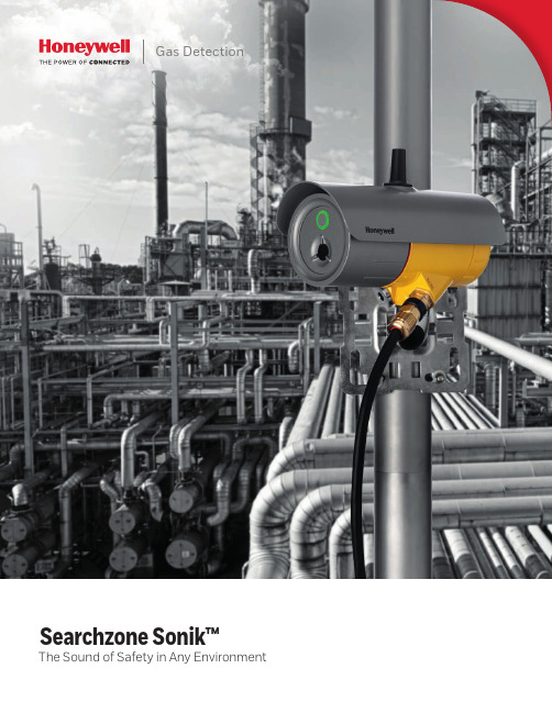
Gas DetectionSearchzone Sonik™The Sound of Safety in Any EnvironmentThe Hazard is Blowing in the WindField studies have shown that around 30% of flammable gas leaks can go undetected because the gas is blown away by the wind. But if the weather conditions change, and the wind drops, the chances are that a flammable gas cloud might build up and trigger incidents and hazards.Since traditional point and open-path devices cannot detect leaks unless the gas reaches the sensor, the need arose for a revolutionary and complementary type of gas detectiontechnology. Instead of waiting for the gas to reach the detection device, an ultrasonic detector operates by responding to the sound created by high-pressure gas leaks at source.Suppose you are servicing an ultrasonic device that complements the point and open path gas detectors of an offshore platform. It’s raining, the wind is blowing heavily, and you’re on a slippery deck, a long way below the Searchzone Sonik you need to reach. Concerned about working at heights, in awkward positions that may even threaten your safety? Think again. Thanks to an easy-to-use mobile app and a dedicated testing tool, you can connect from ground level and test the Searchzone Sonik remotely, without exposing yourself to hazards. All you need to do is to stand on the deck, connect with your smartphone, and use the testing tool to check the detector’s response – it’s as easy as 1, 2, 3 to have the high ground.Search. Detect. Protect.ULTRASONICALLYYou Own the High GroundHow do you sense what you can’t hear?Since gas does not need to come into contact with their sensors, ultrasonic (or acoustic)detectors respond instantly upon “hearing” the distinct sound pattern of a leak, operating at a frequency outside the range of human hearing. Unaffected by airflows and adverse weatherconditions, they are particularly suited to open and well-ventilated areas, such as floating production storage and offloading vessels, gas turbine power plants, compressor stations, gas storage facilities, petrochemical processing plants, refineries, or offshore and onshore oil and gas installations.Searchzone Sonik – Safe and Ultra soundThe new Honeywell Searchzone Sonik is a robust and reliable gas leak detector that will efficiently “hear” the loss of containment of any high-pressure gas within its listening zone. An advanced, SIL 2 certified, hazardous area ultrasonic gas leak detector, the Searchzone Sonik responds to the ultrasonic sound pressure level produced by pressurized gas leaks and is therefore unaffected by environmental conditions.Searchzone Sonik is factory calibrated. Its robust sealed design with no moving parts and the solid-state sensor allow for mounting in any orientation, even in the harshest environments. The gas leak detector will respond quickly to a gas leak within a sensing range radius of typically 20m (65 ft), dependent upon background noise. The intelligent background noise detection system allows the detector to be set up for maximum sensitivity while Focus Mode means that the detection area can be restricted to only include the hazard being monitored. This way you have confidence that you’ll always stay safe and ultra sound.Normal Mode will detect ultrasonic noise from a wide angle, which is ideal for areas that have lower or constant levels of background noise. However generally you will generally know where the potential source of the leak is.That is where Searchzone SonikTM comes into it’s own. Switch to Focus Mode (patent pending) and Searchzone SonikTM will enable special algorithms that effectively screen ultrasonic noise generated outside of the specific area of interest. This dramatically reduces the risk of alarms from spurious noise sources.Bluetooth ConnectivitySet-up and interrogation from ground level via Bluetooth using a dedicated application on mobile phones or tablets.Harsh Weather Conditions? Ultra Gas Detection Additions.Safety, Reliability and Comfort. On the Spot.• Provides reliable gas leak detection in a wide range of applications and working environments By using a solid state sensor, completely sealed from moisture and contaminants, the Searchzone Sonik will identify gas leaks even in the harshest environments and adverse weather conditions.• Lowers the risks of false alarms Thanks to its background noise detection system, the detector has maximum sensitivity and is immune to false alarms produced by process or maintenance activities.• Increases mobility and ease of use You can test your Searchzone Sonik and run confidence checks on your smartphone from up to 20m (65 ft) away. • Minimizes cost of ownership and saves time The Searchzone Sonik is easy to install, commission and maintain; and by using the dedicated mobile app, you can access it in the blink of an eye.• Ensures reliable response in case of emergencies With a Safety Integrity Level rating of 2, the Searchzone Sonik is appropriate for applications requiring an emergency shutdown and other automatic controls.• Prevents fires, explosions and toxic exposure By identifying any high pressure gas leak, the Searchzone Sonik allows proactive action to avoid fatal hazards that might endanger the workers’ life and the integrity of your business assets.Instrument Status at a Glance The Searchzone Sonik features a bright indicator light – green, yellow, red, or blue – providing clear indication of the instrument status.Inbuilt Diagnostics and Full Operational Logs Enables post-event analysis to assess overallperformance and allows security checks.No Moving PartsThe solid-state sensors work flawlessly even in the harshest environments and don’t need additional calibration.Robust Materials Low copper aluminum or stainless steel housing.Simple Installation and AlignmentThe versatile adjustable mount issupplied as standard and features graduated 3 degrees of freedomenabling easy mechanical set-up with a wide range of mounting options.Wide Zone Coverage20m (65 ft) detection radius, dependent upon background ultrasonic noise levels.Focus ModeEffectively an ultrasonic screen. Ignore sources of spurious noise to the sidesand behind the detector so that it only monitors the immediate hazard.Complements Existing Gas DetectorsThe Searchzone Sonik seamlessly integrates with existing point and open-path detectors in the gas detection layer.Afraid of Missing Gas Leaks? Set Your Mind at Ease .Ease of Operation•Robust, solid state sensor design, fit fordemanding environments including pressure wash-downs.• Factory calibrated – no field calibration needed.• Built-in test and diagnostics to maintain operation.•A wide range of outputs to enable system design, including 4 to 20 mA, HART, Modbus, Relays.•Bright light indicator for safety awareness; a unit needing maintenance is easier to locate.•Real-time detection readings and full logging simplify asset management.Ease of Installation•Universal mount with three degrees of freedom enables pole, wall, or strut mounting and easy alignment with the area to be covered.• Wiring compartment with angled cable entry and plugged terminals, separated from the sensing electronics.•App for smartphones and tablets withinstallation guide and logging helps set-up and asset management.GAS JOURNEYSearchzone Sonik applicationsC OMP RE SS ORG A S P R OC E S S I N G P L A N TC O M P R E S S O RC O M P R E S S O RL AR G E I N D U S T R I A L (E GP O W E R P L A N T )R E S I D E N T I A LM E T E R I N GN A T U R A L G A S PR O D U C T I O N L N G T R A N S P O R T A T I O N BY S E A , R A I L O R R O A D N A T U R A L G A S PR O D U C T I O N L NG T ER MI NA LR ES I DE N T I ALC OMME RC IA LS TO RA GEG AT EST AT IO NApplications and Operating EnvironmentProductionExploration vessels • Wellheads • Compressors • Metering skids • Valves.StoragePumps • Valves • Seals.Gathering and ProcessingCompressors • Processing plant • Turbines • Gas safety valves.Transmission and DistributionCompressors • Pipelines • Metering stations • Valves.Ease of Commissioning• The high visibility bright light provides clear indication of the device status.•No need to work at height thanks to the ability to run remote set-up using the Bluetooth app on your phone or tablet.• The easy-to-use Ultrasonic Test Tool enables fast checking of the area of coverage. •Automatic generation of commissioning log.Ease of Maintenance• The reliable internal self-testing and diagnosis enable pro-active maintenance.• Via a Bluetooth app, non-intrusive interaction reduces maintenance time and safety risks.• Simple module replacement if necessary; plug and play.•Automatic generation of maintenance logs.Searchzone Sonik_DS01203_V1_0418_A4_EN © 2018 Honeywell International Inc.Find out moreFor more information visit:Europe, Middle East, Africa**************************Americas***********************Asia Pacific**************************Technical ServicesEMEA:**********************US:***************************AP:***************************Dedicated to Your Safety for More than 50 YearsAs the industry leader for more than 50 years, Honeywell is the partner that workers worldwide trust to provide reliable gas detection. Honeywell proudly stands behind each fixed or portable gas detection product, built to withstand the most rigorous needs and to meet or exceed applicable requirements and standards.Even the best products need to be serviced regularly. Each Honeywell service contract is designed to help maximize your hardware uptime while minimizing your related costs and risks to your production and employees’ health.For a tailored gas detection solution to meet the requirements of your applications and industry ask your sales representative or visit /products/Searchzone-SonikWhile every effort has been made to ensure accuracy in this publication, no responsibility can be accepted for errors or omissions. Data may change, as well as legislation, and you are strongly advised to obtain copies of the most recently issued regulations, standards, andguidelines. This publication is not intended to form the basis of a contract.。
IFD吸气式感烟火灾探测器用户操作手册
CIRRUS PRO火灾侦测器用户手册目录1.0简介 (2)1.1型号和设备 (3)2.0 定期检修 (4)2.1 定期检查 (4)2.1.1 每天检查 (4)2.1.2 三个月检查 (4)2.1.3 年度检查 (4)3.0 使用者指引 (5)3.1 面板指示和控制 (5)3.2 面板显示 (5)3.2.1 主功能选单 (7)3.2.2 实时图形表示 (7)3.2.3 单位/管显示 (8)3.2.4 事件讯息 (8)3.2.5 历史图形 (9)3.2.6 密码 (9)3.2.7 维修讯息 (10)4.0 侦错 (11)4.1 错误讯息列表 (11)4.2 侦测单元上的错误码 (11)5.0 侦测器规格 (12)1.0简介本手册详述了Cirrus Pro Series Aspirating Fire Detectors的安装、测试、服务以及使用方法。
背景众所皆知当材料过热时会产生比可见光波长还小的粒子,而且其数量远远超过在正常环境下存在的粒子数。
Cirrus Pro侦测器利用Wilson的云雾室理论来侦测火的早期及其它各阶段所产生的次微粒子。
经过过滤的空气样本经由离心风扇传送到侦测器,其中一部份被送入增湿器中。
在接近100%的相对湿度下,空气样本被吸入云雾室。
因为真空样本在迅速的膨胀和降温过程中,使水气凝结在小粒子表面而形成“云”。
因此,这些由温度变化产生的粒子而造成的“云”会被云雾室的测量系统侦测。
云的密度会以相称的粒子数量来表现。
侦测的结果是一个连续的讯号,其对应于粒子的浓度,且此讯号用来提供有4个顺序的警报。
Cirrus Pro侦测器有自我管理系统,会持续的监视其正常的操作。
任何问题会立即有面板灯号、蜂鸣器及失误继电器发出警告。
Cirrus Pro侦测器将失误数据、背景粒子浓度及事件数据储存在本机内存中,这些数据可以用选购的Cirrus窗口软件来存取及输出。
选购的面板显示器可以用来做结构的选项及显示全部的数据,面板显示器可以安装在侦测器上或装在远程,利用网络可监控到32个侦测器或面板显示器。
Edwards GXS系统泡沫吸吸气器说明书

Exhaust silencer 5Exhaust silencerCAUTION The operating procedures detailed in the GXS System Instruction Manual - M588-00-880 must be adhered to, in particular Section 3 and 5.CAUTION All pipe work that is connected to the exhaust silencer must be self supporting and must not create any misalignment or stress at the connection point to the exhaust silencer.WARNINGBefore the exhaust silencer is fitted to the pump, the pump must be secured as describe in the pump manual.WARNING The exhaust silencer must be removed from the pump before the pump can be moved.WARNINGThis exhaust silencer is designed for ATMOSPHERIC use only; do not pressurise.WARNING Leak test the system after installation and seal any leaks found to prevent leakage of dangerous substances out of the system and leakage of air into the system.WARNINGCan cause muscle strain or back injury. Use lifting aids and proper lifting techniques when removing or replacing. Refer to Section 5.3for weight information.WARNINGHot surface.Exhaust silencer5.1Description There are two types of exhaust silencer that attenuate the noise from the GXS dry vacuum pumping systems.Refer to Figure42. The first exhaust silencer type is manufactured in both painted carbon steel and stainless steel options (to suit applications) and is designed to hold a volume of liquid or particulates that maybe produced during your process. This exhaust silencer can be drained without disassembly; it is also possible to clean and remove any contaminates with minimal part removal.Figure 42 - Wet process exhaust silencerRefer to Figure43. The second exhaust silencer type is mounted vertically. Manufactured in stainless steel only, this exhaust silencer is designed for clean and dry processes. Easy to disassemble from the GXS pumping system, it is simple to clean and remove any contaminates with minimal parts removal.Exhaust silencer Figure 43 - Dry process exhaust silencerA.GXS160 and GXS250B.GXS450 and GXS750Exhaust silencer5.2Physical data Figure 44 - M58808161 GXS exhaust silencer 100 ctrs assembly - carbon steel Figure 45 - M58808162 GXS exhaust silencer 100 ctrs assembly - stainless steelExhaust silencer Figure 46 - M59838161 GXS exhaust silencer 150 ctrs assembly - carbon steelFigure 47 - M59838162 GXS exhaust silencer 150 ctrs assembly - stainless steelExhaust silencer Figure 48 - NKB530000 iF exhaust silencer - stainless steelExhaust silencerFigure 49 - NR5009000 iF400 exhaust silencer5.3Technical dataFor technical data relating to the exhaust silencers, refer to Section6.3.5.4InstallationFor exhaust silencer installation instructions, please refer to Section6.Exhaust silencer 5.5OperationThe exhaust silencer is a passive device and therefore no operating procedures are required. Follow the points below to ensure you operate your exhaust silencer safely:●Ensure the exhaust silencer is correctly fitted before you use your GXS dry pump.●Do not touch the exhaust silencer when it is hot.●Avoid contact between the exhaust silencer and combustible materials, plastics or electrical cables.●Check the efficiency of your exhaust silencer regularly . A decrease in pump performance could indicate that the exhaust silencer is becoming blocked with deposits or condensate from your pump exhaust. Remove the silencer and drain it, or clean it as described in Section 5.6.●Check the inlet and outlet connections weekly to ensure that they are secure.5.6Maintenance 5.6.1Safety information●Isolate the dry pumping system and other components in the process system from the electrical supply so that they cannot be operated accidentally.●Allow the exhaust silencer to cool to a safe temperature before starting any maintenance. Do not touch the exhaust silencer when it is hot.●T ake suitable precautions when you maintain the exhaust silencer especially if it has been contaminated with dangerous process materials.●Replace the exhaust silencer if it becomes damaged or blocked.WARNINGObey the safety instruction given below and take note of appropriate precautions. If you do not you can cause injury to people and damage equipment.WARNINGPersonal protective equipment should be checked and used as specified by its supplier. If theexhaust silencer has been exposed to hazardous chemicals, the use of suitable protective glovesand clothing along with a respirator is recommended if contact with substances is anticipated.Exhaust silencer 5.6.2CleaningThe exhaust silencers should be cleaned and maintained in accordance with the procedures detailed in the OEM's Service Manuals as listed in Table 50.The exhaust silencers listed below are for clean applications only, and therefore cleaning is not required:●NKB530000 IF Silencer stainless steel.●NR5009000 IF400 Silencer .Note:If cleaning is attempted, be aware that any fluids used could get trapped within the chambers of thesilencer, and ejected on start-up of the pumping system.5.6.3Leak testingAfter maintenance of the exhaust silencer and before the pumping system is used, it is important that the system is leak tested to prevent the possible leakage of hazardous substances.5.7Storage and disposal5.7.1StorageIf the exhaust silencer will not be used immediately:1.Drain and clean the exhaust silencer .2.Protect the flange face and place the exhaust silencer in a sealed polythene bag.3.Store in a cool dry place.5.7.2DisposalDispose of the exhaust silencer in accordance with local and national safety and environmental requirements.Table 50 - Exhaust silencer OEM service manuals Item Number Description OEM Service ManualM58808161GXS exhaust silencer 100 ctrs assembly - carbon steel DischargeSlcrManualNW40US-0811M58808162GXS exhaust silencer 100 ctrs assembly - stainless steel DischargeSlcrManualNW50US-0811M59838161GXS exhaust silencer 150 ctrs assembly - carbon steelM59838162GXS exhaust silencer 150 ctrs assembly - stainless steelThis page has been intentionally left blank.Exhaust silencer mounting assembly 6Exhaust silencer mounting assembly6.1DescriptionThis exhaust silencer is mounted horizontally and either bolted to the side of the pump when a side exiting exhaustis fitted (refer to Figure50), or free standing at the rear of the pump when a rear exiting exhaust is fitted (refer toFigure51).Figure 50 - Side exiting exhaust mountingFigure 51 - Rear exiting exhaust mountingExhaust silencer mounting assembly6.2Physical data Figure 52 - M58808009 horizontal silencer mount - 100 ctr*Silencer supplied separately.Exhaust silencer mounting assembly Table 51 - M58808009 horizontal silencer mount - 100 ctr check listItem Qty Description Check11Drain valve assembly❑21NW32/40 clamping ring❑31NW40 trapped O-ring - Viton 9830 / PTFE❑42GXS raised support - 100 ctr❑53M10 spring washer - nickel plated mild steel❑73M10 full nut - nickel plated mild steel❑82M10 x 30 hex head screw - nickel plated mild steel❑94M16 spring washer - nickel plated mild steel❑108M16 washer normal - nickel plated mild steel❑114M16 full nut - nickel plated mild steel❑124M16 x 45 hex head screw - nickel plated mild steel❑131M10 x 35 hex head screw - nickel plated mild steel❑141Silencer brace - 100 ctr❑151Silencer mounting - 100 ctr❑164M8 x 25 hex head screw - nickel plated mild steel❑166M10 washer normal - nickel plated mild steel❑174M8 washer normal - nickel plated mild steel❑184M8 spring washer - nickel plated mild steel❑Exhaust silencer mounting assembly Figure 53 - M58808151 rear silencer horizontal mount - 100 ctr*Silencer supplied separately.Table 52 - M58808151 rear silencer horizontal mount - 100 ctr check listItem QTY Description Check11Drain valve assembly❑21Silencer support - horizontal rear 100 ctr❑31Silencer support side bracket - horizontal rear 100 ctr❑41NW40 full nipple - stainless steel❑54M8 spring washer - stainless steel❑68M8 washer normal - stainless steel❑78M8 x 20 hex head screw - stainless steel❑83NW32/40 clamping ring ❑93NW40 trapped O-ring - Viton 9830 / PTFE❑Exhaust silencer mounting assembly Figure 54 - M59838009 horizontal silencer mount - 150 ctr*Silencer supplied separately.Exhaust silencer mounting assembly Table 53 - M59838009 horizontal silencer mount - 150 ctr check list Item QTY Description Check11Drain valve assembly❑21NW50 clamping ring❑31NW50 trapped O-ring - Viton / stainless steel❑42GXS raised support - 150 ctr❑53M10 spring washer - nickel plated mild steel❑66M10 washer normal - nickel plated mild steel❑73M10 nut full - nickel plated mild steel❑82M10 x 30 hex head screw - nickel plated mild steel❑91Silencer brace - 150 ctr❑104M16 spring washer - nickel plated mild steel❑118M16 washer normal - nickel plated mild steel❑124M16 full nut - nickel plated mild steel❑134M16 x 45 hex head screw - nickel plated mild steel❑141M10 x 35 hex head screw - nickel plated mild steel❑151Silencer mounting - 150 ctr❑164M8 x 25 hex head screw - nickel plated mild steel❑174M8 washer normal - nickel plated mild steel❑184M8 spring washer - nickel plated mild steel❑Exhaust silencer mounting assembly Figure 55 - M59808151 rear silencer horizontal mount - 150 ctr*Silencer supplied separately.Table 54 - M59808151 rear silencer horizontal mount - 150 ctr check listItem QTY Description Check11Drain valve assembly❑21Silencer support-horizontal rear 150 ctr❑31Silencer support side bracket - horizontal rear 150 ctr❑41NW50 full nipple - stainless steel❑57M8 spring washer - stainless steel❑68M8 washer normal - stainless steel❑78M8 x 20 hex head screw - stainless steel❑Exhaust silencer mounting assemblyFigure 56 - M58808069 vertical silencer assembly - 100 ctr83NW50 clamping ring❑93NW50 trapped O-ring - Viton / stainless steel❑Table 55 - M58808069 vertical silencer assembly - 100 ctr check listItem QTY DescriptionCheck 11iF silencer❑21NW40 elbow 149 x 98❑32NW40 trapped O-ring - Viton 9830 / PTFE ❑42NW32/40 clamping ring❑Table 54 - M59808151 rear silencer horizontal mount - 150 ctr check list (continued)Item QTY Description CheckExhaust silencer mounting assembly Figure 57 - M59838163 vertical silencer assembly - 150 ctrTable 56 - M59838163 vertical silencer assembly - 150 ctr check listItem QTY Description Check11iF400 silencer❑21NW50elbow❑32NW50 trapped O-ring - Viton 9830 / PTFE❑42NW50 clamping ring❑M588-08-880 Issue BPage 78© Edwards Limited 2013. All rights reserved.Edwards and the Edwards logo are trademarks of Edwards Limited.6.3Table 57 - Silencer mounting technical dataDescriptionPart Number Carbon Steel Silencer Stainless SteelSilencer Inlet and outletFlow Rate (Roughing)m 3/hrAttenuation (at Ultimate Pressure)Pressure TestT o Horizontal silencer mounting - 100 ctrM58808009M58808019M58808031NW40150>10 dB typical 10 barG Rear silencer horizontal mounting - 100 ctrM58808151M58808019M58808031NW40150>10 dB typical 10 barG Horizontal silencer mounting - 150 ctrM59838009M59808019M59808031NW50420>10 dB typical 10 barG Rear silencer horizontal mounting - 150 ctrM59808151M59808019M59808031NW50420>10 dB typical10 barGing suitable lifting equipment and techniques, mount the silencer to the bracket as shown in Figure58. Alignthe inlet flange on the exhaust silencer with the exhaust outlet flange on the dry pump.3.Bolt the silencer to the support bracket using the fasteners provided. Do NOT fully tighten the fasteners. Thisallows for fine adjustment.4.Fit the trapped O-ring between the two flange connections and carefully draw the flanges together using theclamp provided until secured in position. Attention should be given to the alignment of this connection to ensure an efficient seal.5.Tighten all bolts to the recommended torque.Note:Viewed from underneath the pump to show mounting bracket positions for exhaust silencer.A.100 ctr pumpsB.150 ctr pumpsA.100 ctr pumpsB.150 ctr pumps。
XSS1000超声波污泥浓度说明书
控制面板 ........................................................................... 11 菜单结构 ........................................................................... 12 常规设置流程 ................................................................... 13 标定 ................................................................................... 14 第五章 维护 变送器的维护 ................................................................... 17 传感器的维护 ................................................................... 17 第六章疑问 .......................................................................... 18
1
超声波污泥浓度计 时间显示,可设时间间隔自动记录浓度变化趋势线。 可选现场总线接口。
产品 应用
给水厂及污水处理厂: 回流污泥、初沉池、二沉池、浓缩池、污泥脱水等。
工矿企业: 洗煤厂、矿山、造纸、电力矿浆浓度、煤浆浓度、 灰浆浓度、纸浆浓度等。
2
变送器 传感器
二、产 品
超声波污泥浓度计
技术参数: 测量范围:污泥:0~10%
System Sensor 系统气体探测器基底说明书
Specifications
Base Diameter:
6.2 inches (157 mm)
Base Height:
0.95 inches (24 mm)
Weight:
0.3 lb. (137 g)
Mounting:
4-inch square box with or without plaster ring. Min. depth–1.5 inches
Start-up Time:
34.0 Seconds Maximum
- 1、下载文档前请自行甄别文档内容的完整性,平台不提供额外的编辑、内容补充、找答案等附加服务。
- 2、"仅部分预览"的文档,不可在线预览部分如存在完整性等问题,可反馈申请退款(可完整预览的文档不适用该条件!)。
- 3、如文档侵犯您的权益,请联系客服反馈,我们会尽快为您处理(人工客服工作时间:9:00-18:30)。
一般的设计要求如下: • 最大单管长度不超过 100 米(一定要保证最末端采样孔到探测器的气流传输时间不超过120
盛赛尔美国总部
3825 Ohio Avenue St.Charles.IL 60174 电话: (001)630-377-6580 传真: (001)630-377-6495 网址:
西安盛赛尔电子有限公司
中国.西安高新技术开发区团结南路 28 号 电话: (86 29) 85387800 传真: (86 29) 88332959 邮编: 710075 网址:
西安盛赛尔电子有限公司享有并保留一切著作权之专属权利,非经我公司同意,不 得对本手册部分或全部从事增删、改编、翻印或仿制之行为。
1
I56-1000-01C
公司简介
西安盛赛尔电子有限公司是世界 500 强之一的霍尼韦尔集团(HONEYWELL)的子公司美国盛赛尔公司 (SYSTEM SENSOR)在西安投资兴办的专业火灾探测器生产企业,是目前国内最大的火灾探测器专业生 产商,公司全套引进美国盛赛尔公司(SYSTEM SENSOR)的先进技术、工艺、管理系统、质量保证体系 和现代化的生产加工设备,生产各类火灾探测器及配套件产品,产品的质量、性能、技术指标均与美国 本部完全一致。公司产品已通过美国 UL 测试及中国国家消防电子产品质量监督检验中心的检验,主要 产品设计都获得了国家专利。公司已通过 ISO9000 国际认证(美国 UL 公司审核)及公安部消防产品合 格评定中心的 GBT19000 质量体系认证,获准使用 3C 认证标志。公司是 2000 年度中国消防电子产品质 量体系认证复查检验的首家唯一免检企业,2002 年再次获得唯一免检称号,并连续入选中国消防产业 30 强论坛单位。
High/高 High/高
Ceiling Height Limit/ 天花板高度限制
General/
一般情况 10.50m 12.00m 15.00m 8.00m 10.50m 4.00m
Rapid Attendance/
快速响应 15.00m 17.00m 21.00m 10.00m 15.00m 6.00m
如果少于 10%的被保护区域超出了上表天花板高度限制,可以参考<10%一栏的数据。如果是“人”字坡顶,那么可以参 考快速反应栏的数据。
3 系统设计
3.1 设计基本原则 吸气式探测器通常安装在需要提供高于普通探测器的灵敏度,希望能提供早期报警的区域,或安装在传统探测器无法提供
探测的区域,比如: • 接触或者维护困难区域; • 高顶层空间; • 需天花板内安装; • 机柜; • 电缆桥架。 在设计吸气式烟雾探测系统时,首先要定义对系统的性能需求以及相关标准、规范的要求。系统的探测灵敏度设置可根据
4
I56-1000-01C
图一 通风管路安装方式 3.1.2 常规环境管路设置
此时系统通常将采样点按传统点式探测器布置的位置来布置。如果需要达到增强型灵敏度或者高灵敏度,每个探测点的常 规保护面积需进一步减少:
因为烟雾需要热量才能上升到一定高度,如果火势非常小,那么只有最小范围的烟雾能到达高空。考虑到这些,必须以高 于普通区域的标准来测试系统,下表详细说明了吸气式烟雾探测系统的推荐测试方法及高度限制:
美国盛赛尔公司(SYSTEM SENSOR)是一个全球性的研制开发、生产、销售火灾报警探测器及其配套件、 声光显示产品、水流指示器的跨国公司,年产各类探测器 800 多万只,与遍布全世界的 40 多家著名报 警控制器厂家的产品相配套,公司总部在美国芝加哥。西安盛赛尔电子有限公司是其设在亚洲的生产基 地,主要负责中国、东南亚、澳州、南美洲等市场的供货和服务。现在业务还扩展到北美洲、欧洲、及 美国等国家。
西安盛赛尔电子有限公司
XI'AN SYSTEM SENSOR ELECTRONICS, LTD.
吸气式感烟火灾探测器设计使用手册
前言
本手册重点介绍了盛赛尔公司吸气式感烟火灾探测器的设计与使用方法,我们力求使 产品的信息做到最新、最准确,希望本手册能满足您对盛赛尔产品的了解。如有疑问或 需要了解进一步的产品信息,请与我们及时取得联系。
Ceiling Areas ﹤10% of main area/ 少于 10%的被保护区域内的天花板
高度
General/ Rapid Attendance/
一般情况 12.50m 14.00m 18.00m 9.00m 12.50m 5.00m
快速响应 18.00m 21.00m 26.00m 11.00m 18.00m 7.00m
该探测器还具有故障自诊断能力,当空气采样管发生堵塞、破损;风机发生故障;系统出现问题等,探测器会给出相 应的故障信息。
2 系统组成
该系统由如下设备组成,根据现场需要还可以进行增加或减少。 • 吸气式探测器; • 专用电源箱; • 吸气管路; • 配接的火灾报警控制器(可选配); • 可配接的显示、控制设备(如声光显示等,可选配)。
全新的西安盛赛尔电子有限公司新厂房位于西安高新技术产业开发区,占地面积 30 余亩,投资额 1000 万美元,新厂房完全按照现代化生产企业的布局而建,厂房内的布局更趋合理,完全满足了公司的 生产需求。公司将以“提供高质量的产品、合理的价格、及时交货及优质服务使用户满意”为服务宗旨, 愿与国内外火灾自动报警设备生产厂家和从事消防报警行业的单位以多种方式进行合作,共同开发国内 外市场。
表一 灵敏度及对应使用高度源自Sensitivity Test/
灵敏度测试
Normal/正常 Normal/正常 Normal/正常 Enhanced/增强 Enhanced/增强
High/高
System Sensitivity/
系统灵敏度
Normal/正常 Enhanced/增强
High/高 Enhanced/增强
3
I56-1000-01C
1 概述
该吸气式感烟火灾探测器是一种具有报警功能及继电器输出的空气管路采样式感烟火灾探测器,主要用于需要高灵敏 度烟雾探测的场所及高洁净、高大空间、高温、高湿或具有强电磁辐射等环境。
它通过内部的一个抽气设备产生低气压,带有若干个小孔的空气采样管从被监控区吸入空气,这些空气被吸入采用独 特设计的激光采样检测室内进行分析,相应的微处理器对数据进行综合处理,判断是否有火警发生,如有则给出相应的声 光及文字显示信息。
电邮: sales@
2
I56-1000-01C
目录
1 概 述… … … … … … … … … … … … … … … … … … … … … … … … … … … … 4
2 系统组成… … … … … … … … … … … … … … … … … … … … … … … … … … … … … … 4 3 系统设计… … … … … … … … … … … … … … … … … … … … … … … … … … … … … 4 3.1 设计基本原则 … … … … … … … … … … … … … … … … … … … … … … … … … 4 3.2 采样管网安装… … … … … … … … … … … … … … … … … … … … … …… … … … … … … 7 3.3 采样孔孔径控制… … … … … … … … … … … … … … … … … … … … …… … … … … … … …11 3.4 电源… … … … … … … … … … … … … … … … … … … … … … …… … … … … … … …12 3.5 连接至其它系统… … … … … … … … … … … … … … … … … … … …… … … … … … … …12 4 产品介绍及操作… … … … … … … … … … … … … … … … … … … …… … … … …… … … …12 4.1 概述… … … … … … … … … … … … … … … … … … … …… … … … … … … … … … …12 4.2 主要特性及技术指标… … … … … … … … … … … … … … … … … … …… … … … … … … … … … …12 4.3 基本功能… … … … … … … … … … … … … … … … … … … …… … … … … … … … … … …12 4.4 操作指南… … … … … … … … … … … … … … … … … … … …… … … … … … … … … … …13 4.5 接线指导… … … … … … … … … … … … … … … … … … … …… … … … … … … … … … …17 4.6 安装与调试维修… … … … … … … … … … … … … … … … … … … …… … … … … … … … … … …18 4.7 维修… … … … … … … … … … … … … … … … … … … …… … … … … … … … … … …21 5 灵敏度… … … … … … … … … … … … … … … … … … … … … … … … … … … … … … … …21 5.1 响应时间… … … … … … … … … … … … … … … … … … … …… … … … … … … … … … …21 5.2 常规环境管路方式… … … … … … … … … … … … … … … … … … … …… … … … … … … … … … …22 5.3 通风口管路方式… … … … … … … … … … … … … … … … … … … …… … … … … … … … … … …22 6 感烟探测器的局限性… … … … … … … … … … … … … … … … … … … …… … … … … … … …23 7 产品标签日期码构成说明… … … … … … … … … … … … … … … … … …… … … … … … … …23 8 质量保证 … … … … … … … … … … … … … … … … … … … … … … … … … … …23