设计手册20010905最新版..
R095-AQC设计说明书-英文版
Design InstructionR095-SM-1Prepared by:Reviewed by:Verified by:Approved by:July, 2010Changsha Boiler Plant Co., Ltd P.R.ChinaContent I PrefaceII Boiler parametersIII Basic sizeIV Design introductionV Structure introductionI PrefaceAccording to the parameters requirement of cement kiln AQC tail gas, on the basis of our mature structure of waste heat boiler serial product and domestic and overseas latest cement kiln waste heat boiler, we developed the QC290/370-24(8)- 1.6/350(0.35/190) waste heat boiler. It is a kind of waste heat boiler for pure low-temperature cement kiln waste heat power generation which fulfills the AQC tail gas waste heat recovery of 5000~6000t/d clinker production of cement industry. This boiler can not only make effective use of the waste heat, but facilitate the operation of the following process, reducing the product cost and energy product, strengthening the company’s marketing competitiveness. Meanwhile, it also fit the national energy policy and will be an irresistible trend in the future.II Boiler parametersi) Inlet exhaust gas parameters(1) Inlet exhaust gas quantity 290000Nm3/h(2) Inlet exhaust gas temperature 370℃(3) Inlet exhaust gas dust quantity ~30g/Nm3(4) Exhaust gas content dusty airii) Design parameters(1) High pressure steam sectionRated evaporation 24t/hRated steam pressure (gage pressure) 1.6MPaRated steam temperature 350℃Blowdown rate 1%(2) Low pressure steam sectionRated evaporation 8t/hRated steam pressure (gage pressure) 0.35MPaRated steam temperature 190℃Blowdown rate 1%(3) Feed water temperature 45℃(4) Outlet exhaust gas temperature 95℃(5) Boiler air leakage ratio ≤2%In order to meet the steam quality requirement, feed water should refer to GB/T12145 Quality Criterion of Water and Steam for Steam Power Equipment.III Basic sizeHigh pressure drum center 25520mm Boiler width (center line distance between left and right column) 6600mm Boiler depth (center line distance between front and rear column) 8840mm Boiler maximum width (include platform) 11550mm IV Design introductionThis boiler is natural circulation and vertical layout. The system adopts double pressure & double flue structure.Flue gas enters from the boiler top and then passes the high pressure superheater, high pressure evaporator I, II, low pressure superheater, high pressure economizer II, low pressure evaporator, high pressure economizer I, common economizer and low pressure economizer, and then exhausts from the bottom exit, entering the dust- precipitator of the AQC.Feed water (temperature 45℃) is introduced to the low pressure economizer and common economizer by means of a water pump and then heated in the low pressure economizer and sent to low pressure drum; Water in the common economizer is heated and then introduced to the boiler high pressure economizer and kiln SP boiler economizer respectively. Water in the high pressure economizer is heated and then introduced to high pressure drum. Water in the high (low) pressure drum enters each evaporator through its downcomer, and then the heated steam-water mixture is introduced to drum again. After that, the saturated steam comes out of the drum and then enters each superheater, where it is heated and generates the superheated steam of rated pressure.The heat source of this boiler comes from the exhaust gas of the clinker cooler of cement kiln AQC. Its temperature is low but contains certain clinker dust, which has apoor adherence but strong rigidity, easy to wear the heating surface. In order to reduce the boiler wear-out and improve boiler heat efficiency and achieve the safe and stable operation, corresponding measures are taken in the boiler design: annular-finned tubing applied for the boiler superheater, evaporator and economizer heating tubes, organized the effective exhaust gas flow field, strengthened heat transfer effect, thus, greatly reduced the wear-out of heating surface and extended its service life.The boiler setting wall adopts light type structure furnace wall. In order to reduce the boiler air leakage factor and ensure the stability of cement production system, the seals of furnace wall manhole, wall liner tube (header) and casing joint are carefully designed.V Structure Introduction1. Drum and internalsThe inner diameter of high pressure boiler drum isΦ1500mm, wall thickness 22mm; the inner diameter of low pressure boiler drum isΦ1200mm, wall thickness 12mm; They are made of Q245R steel plate.The primary separating unit is underwater pore plate structure; the secondary separating adopts wave form plate separator located on the top of the drum.Boiler normal water level is on the center line, the maximum and minimum safe level is ±75mm from normal water level.2. SuperheaterThe flue gas duct is assembled with a high pressure superheater and a low pressure superheater. Each superheater is composed of inlet/outlet headers and tube banks. The header is made of ¢219 steel tube of 20/GB3087; The tube bank is made of ¢38 tube(20/GB3087) with welded annular fins.3. EvaporatorThe flue gas duct is assembled with two high pressure evaporators and two low pressure evaporators. Evaporator is composed of inlet/outlet headers and tube banks. The header is made of ¢219 steel tube of 20/GB3087, located in the flue gas duct; The tube bank is made of ¢42 tube(20/GB3087) with welded annular fins.The feed water of high & low pressure evaporator tube banks is provided by four downcomers(20/GB3087) of ¢108 and ¢89; The outlet pipe of each tube bank is composed of four outlet pipes(20/GB3087) of ¢133and ¢108.4. EconomizerThe flue gas duct is assembled with two high pressure economizers, two common economizers and one low pressure economizer. Each superheater is composed of inlet/outlet headers and tube banks. The header is made of ¢219 steel tube of 20/GB3087; The tube bank is made of ¢32 tube(20/GB3087) with welded annular fins.Superheater, evaporator, economizer and the frame constitute their independent channel box, delivered as assembled, reducing the field installation cycle. Channel boxes are divided into left and right ones with symmetrical distribution.5. Framework/CasingThis boiler adopts steel frame construction; the boiler heating surface is fixed by supporting structure.This boiler adopts inner/outer casing; inner casing is made of steel plate with a wave form color plate as outer casing, which ensures the boiler tightness and appearance.6. Platform ladderThe platforms are set on places like the operation, maintenance, inspection door and supported on the steel frame.7. Boiler wallsThe boiler adopts light type furnace wall of alumina-silicate fiber felts and plasters.This boiler can be used in the open air or half open air.。
机械设计手册第五版(目录)-推荐下载

机械设计手册第五版(目录)第一卷第1篇:一般设计资料第一章、常用基础资料和公式第二章、铸件设计的工艺性和铸件结构要素第三章、锻造和冲压设计的工艺性和结构要素第四章、焊接和铆接设计的工艺性第五章、零部件冷加工设计工艺性与结构要素第六章、热处理第七章、表面技术第八章、装配工艺性第九章、工程用塑料和粉末冶金零件设计要素第十章、人机工程学有关功能参数第十一章、符合造型、荷载、材料等因素要求的零部件结构设计准则第十二章、装备要求及设备基础第2篇:机械制图、极限与配合、形状和位置公差及表面结构第一章、机械制图第二章、极限与配合第三章、形状和位置公差第四章、表面结构第五章、孔间距偏差第3篇:常用机械工程材料第一章、黑色金属材料第二章、有色金属材料第三章、非金属材料第四章、其他材料及制品第4篇:机构第一章、机构分析的常用方法第二章、基本机构的设计第三章、组合机构的分析与设计第四章、机构参考图例第二卷第5篇:连接与紧固第一章、螺纹及螺纹连接第二章、铆钉连接第三章、销、键和花键连接第四章、过盈连接第五章、胀紧连接和型面连接第六章、锚固连接第七章、粘结第6篇:轴及其连接第一章、轴和软轴第二章、联轴器第三章、离合器第四章、制动器第7篇:轴承第一章、滑动轴承第二章、滚动轴承第三章、直线运动滚动功能部件第8篇:起重运输机械零部件第一章、起重机械零部件第二章、输送机械零部件第9篇:操作件、小五金及管件第一章、操作间及小五金第二章、管件第三卷第10篇:润滑与密封第一章、润滑方法及润滑装置第二章、润滑剂第三章、密封第四章、密封件第11篇:弹簧第一章、弹簧的类型、性能及应用第二章、圆柱螺旋弹簧第三章、截锥螺旋弹簧第四章、蜗卷螺旋弹簧第五章、多股螺旋弹簧第六章、蝶形弹簧第七章、开槽蝶形弹簧第八章、膜片弹簧第九章、环形弹簧第十章、片弹簧第十一章、板弹簧第十二章、发条弹簧第十三章、游丝第十四章、扭杆弹簧第十五章、弹簧的特殊处理及热处理第十六章、橡胶弹簧第十七章、橡胶---金属螺旋复合弹簧(简称复合弹簧)第十八章、空气弹簧第十九章、膜片第二十章、波纹管第二十一章、压力弹簧管第12篇:螺旋传动、摩擦轮传动第一章、螺旋传动第二章、摩檫轮传动第13篇:带、链传动第一章、带传动第二章、链传动第14篇:齿轮传动第一章、渐开线圆柱齿轮传动第二章、圆弧圆柱齿轮传动第三章、锥齿轮传动第四章、涡杆传动第五章、渐开线圆柱齿轮行星传动第六章、渐开线少齿查行星齿轮传动第七章、销齿传动第八章、活齿传动第九章、点线啮合圆柱齿轮传动第十章、塑料齿轮第四卷第15篇:多点啮合柔性传动第一章、概述第二章、悬挂安装结构第三章、悬挂装置的设计计算第四章、柔性支撑的结构形式和设计计算第五章、专业技术特点第六章、整体结构的技术性能、尺寸系列及选型方法第七章、多点啮合柔性传动动力学计算第16篇:减速器、变速器第一章、减速器设计一般资料第二章、标准减速器及产品第三章、机械无极变速器及产品第17篇:常用电机、电器及电动(液)推杆及升降机第一章、常用电机第二章、常用电器第三章、电动、电液推杆及升降机第18篇:机械振动的控制及利用第一章、概述第二章、机械振动的基础资料第三章、线性振动第四章、非线性振动机随机振动第五章、振动的控制第六章、机械振动的利用第七章、机械振动测量技术第八章、轴和轴系的临界转速第19篇:机架设计第一章、机架结构概论第二章、机架设计的一般规定第三章、梁的设计与计算第四章、柱和立架的设计与计算第五章、桁架的设计与计算第六章、框架的设计与计算第七章、其他形式的机架第20篇:塑料制品与塑料注射成型模具设计第一章、塑料制品设计第二章、塑料注射成型工艺第三章、塑料注射成型模具设计第四章、热固性塑料注射成型模具第五章、塑料注射成型模具实例第六章、塑料注射成型模具标准模架第七章、塑料注射成型模具设计程序与CAD第五卷第21篇:液压传动第一章、基础标准与液压流体力学常用公式第二章、液压系统设计第三章、液压基本回路第四章、液压工作介质第五章、液压泵和液压马达第六章、液压缸第七章、液压控制阀第八章、液压辅助件及液压泵站第九章、液压传动系统的安装、使用和维护第22篇:液压控制第一章、控制理论基础第二章、液压控制概述第三章、液压控制元件、液压动力元件、伺服阀第四章、液压伺服系统的设计计算第五章、电液比例系统的设计计算第六章、伺服阀、比例阀及伺服缸主要产品简介第23篇:气压传动第一章、基础理论第二章、压缩空气站、管路网络及产品第三章、压缩空气净化处理装置第四章、气动执行元件及产品第五章、方向控制阀、流体阀、流量控制阀及阀岛第六章、电--气比例/伺服系统及产品第七章、真空元件第八章、传感器第九章、气动辅件第十章、新产品、新技术第十一章、气动系统第十二章、气动相关技术标准及资料第十三章、气动系统的维护及故障处理。
最新设计版用户手册(总平面)资料

江门市修建性详细规划电子报批二期设计版用户手册广州城市信息研究所有限公司江门市城市地理信息中心2009 年11 月目录第1章.运行需求 (5)1.1硬件环境 (5)1.2软件环境 (5)第2章.系统功能及操作 (5)2.1概述 (5)2.2设计 (5)2.2.1项目属性 (5)2.2.2设置关联单体属性 (6)2.2.3显示图形填充 (7)2.2.4关闭图形填充 (7)2.2.5图层属性 (7)2.2.6属性复制 (12)2.2.7批量转换 (12)2.2.8标注 (12)2.2.9总平版本转换 (13)2.3检测 (13)2.3.1属性数据 (13)2.3.2非法拓扑关系 (14)2.3.3必需拓扑关系 (14)2.3.4建筑间距 (15)2.3.5标注检测 (15)2.3.6检测建筑编号 (16)2.3.7属性查询 (16)2.3.8建筑查询统计 (17)2.3.9日照分析 (17)2.3.10文件完整性检测 (19)2.4指标计算 (20)2.4.1用地平衡表 (20)2.4.2技术经济指标表 (21)2.4.3技术经济指标混合计算 (21)2.4.4技术经济指标对照 (22)2.4.5分期用地指标表 (22)2.4.6分期用地指标混合计算 (23)2.4.7分期用地指标对照 (23)2.4.8绿地指标表 (23)2.4.9公共服务设施表 (24)2.4.10建筑面积明细表 (24)2.4.11建筑面积明细混合计算 (24)2.4.12建筑面积明细对照 (25)2.4.13停车场一览表 (25)2.4.14停车场明细表 (26)2.5工具 (26)2.5.1显示/关闭属性输入 (26)2.5.2显示/关闭视点转换 (27)2.5.3显示/关闭指标窗口 (27)2.5.4显示/关闭检测窗口 (27)2.5.5图层工具 (28)2.5.6图库管理 (29)2.5.7清除闪烁 (30)2.5.8提取尺寸 (30)2.5.9删除多义线重复顶点 (31)2.5.10查找句柄 (31)第1章.运行需求1.1硬件环境工作站:P450 以上高档PC机,内存不少于64M服务器:P866以上专用服务器,内存不少于128M1.2软件环境操作系统:用户端Windows 2000/XP/2003服务器Windows 2000/2003图形支持:AutoCAD 2006第2章.系统功能及操作2.1概述按照功能模块划分成四个模块:“设计”、“检测”、“指标”以及“工具”。
建筑设计与实施手册
建筑设计与实施手册1. 引言此手册旨在提供一份全面的指南,涵盖建筑设计的基本原则、实施流程以及项目管理。
无论您是建筑师、工程师、施工人员还是相关领域的专业人士,本手册都将为您提供必要的知识和技能,以顺利开展建筑项目。
2. 建筑设计原则建筑设计应遵循以下原则:1. 功能性:建筑应满足使用需求,为用户提供舒适、安全、便捷的空间。
2. 安全性:建筑应符合国家和地方的安全规范,确保结构安全、防火安全、人身安全等。
3. 经济性:在满足功能和安全性要求的前提下,建筑应具有合理的经济性,包括建设成本和运营成本。
4. 美观性:建筑应具有较高的审美价值,与周边环境协调,体现时代特色。
5. 可持续性:建筑应采用环保材料、节能技术,降低对环境的负面影响,提高资源利用效率。
3. 设计流程建筑设计流程可分为以下阶段:1. 前期调研:收集项目相关资料,了解用地条件、周边环境、用户需求等。
2. 概念设计:提出设计理念,确定建筑形态、空间布局、功能分区等。
3. 方案设计:细化概念设计,完成建筑平面、立面、剖面等设计图纸,并进行分析评估。
4. 施工图设计:根据方案设计,编制详细的建筑施工图纸,包括结构、给排水、电气、暖通等专业图纸。
5. 施工阶段:根据施工图纸,开展建筑施工,确保工程质量。
6. 竣工验收:完成建筑施工后,进行验收,确保建筑符合设计要求和规范。
4. 项目管理项目管理应涵盖以下方面:1. 进度管理:制定合理的项目时间表,监控项目进度,确保按时完成。
2. 成本管理:控制项目成本,合理分配预算,防止浪费。
3. 质量管理:严格执行质量规范,确保工程质量,降低质量风险。
4. 沟通协调:搭建项目团队,明确各成员职责,保持良好的沟通与协作。
5. 合同管理:签订合同,明确合同条款,保障项目权益。
6. 风险管理:识别项目风险,制定应对措施,降低风险影响。
5. 建筑施工技术建筑施工技术包括以下内容:1. 结构施工:掌握各种结构形式的特点和施工方法,确保结构安全。
给水排水设计手册第5册
给水排水设计手册第5册第一章:排水设计基础1.1排水设计的概念和作用排水设计是指根据工程的实际情况和要求,对排水系统进行合理规划和设计,以达到排水顺畅、安全可靠、经济合理的目的。
排水设计在水利工程、城市建设、道路建设等领域发挥着重要作用,能够有效避免水灾和环境污染,保障人民生命财产安全,促进社会经济的可持续发展。
1.2排水设计的原则和要求排水设计的原则包括科学性、全面性、先进性和适用性。
科学性要求设计应该符合水文学原理和水力学原理;全面性要求设计应该充分考虑各种因素的影响和作用;先进性要求设计应该采用最新的技术和方法;适用性要求设计应该针对具体情况进行合理选择。
1.3排水系统的构成排水系统包括市政排水系统、建筑物排水系统、道路排水系统等多种类型。
市政排水系统主要包括雨水管网、污水管网和污水处理设施;建筑物排水系统主要包括屋面排水系统、地面排水系统和室内排水系统;道路排水系统主要包括排水沟、排水管和排水设施。
1.4排水设计的基本步骤排水设计的基本步骤包括调查研究、方案设计、施工图设计和施工管理。
调查研究阶段主要是对地形地貌、降雨情况、排水需求等进行调查和研究;方案设计阶段主要是确定排水系统的类型、布局和容量;施工图设计阶段主要是绘制详细的施工图纸和材料清单;施工管理阶段主要是对施工过程进行监督和管理。
第二章:城市排水系统设计2.1雨水排水系统设计雨水排水系统是城市排水系统中的重要组成部分,其设计主要包括雨水收集、储存和排放。
雨水收集主要是通过建筑物屋面和地面的排水系统收集雨水;储存主要是通过雨水储存设施储存雨水;排放主要是通过排水管网将雨水排放到指定地点。
2.2污水排水系统设计污水排水系统是城市排水系统中的另一个重要组成部分,其设计主要包括污水收集、输送和处理。
污水收集主要是通过建筑物室内排水系统收集污水;输送主要是通过污水管网将污水输送到污水处理设施;处理主要是通过污水处理设施对污水进行处理,达到排放标准。
设计手册最新版实用手册
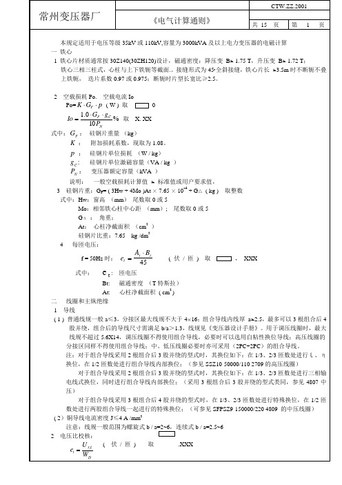
At Bt 45
( 伏 / 匝 ) 取
, XXX
et:
匝电压
Bt: 磁通密度 (T 特斯拉) 2 At: 心柱净截面积 ( cm ) 二 线圈和主纵绝缘 1 导线 ( 1 ) 普通线规一般 a≤3,分接区最大线规不大于 4×16;组合导线内线厚 a≤2.5,最多可以 3 根组合后 4 股并绕,组合后的导线尺寸需满足 b/a>1.3,线规见《变压器设计手册》。用于调压线圈时,最大 线规不超过 5.6X14,调压线圈不得使用组合导线,必要时可以选用自粘性换位导线;高压线圈的 分接区同样不得使用组合导线;中、低压线圈必要时亦可采用(2PC+2PC)的组合导线。 注:对于组合导线采用 2 根组合后 3 股并绕的型式时,其换位如下:在 1/3、2/3 匝数处进行ξ 、η 换位,在 1/2 匝数处进行组合导线内部换位;(参见 SSZ10-50000/110 2709 的高压线圈) 对于组合导线采用 2 根组合后 3 股并绕的型式时,其换位如下:在 1/3、2/3 匝数处进行三相输 电线式换位,同时进行组合导线内部换位;(采用 3 根组合后 3 股并绕的型式类同,参见 4807 中 压) 对于组合导线采用 3 根组合后 4 股并绕的型式时,在 1/3、2/3 匝数处进行特殊换位,在 1/2 匝 数处进行两股组合导线一起进行的特殊换位;(可参见 SFPSZ9-150000/220 4809 的中压线圈) ( 2)铜导线电流密度 J≤4 A /mm2 注意:线规一般范围为螺旋式 b / a=2~6,连续式 b / a=2.5~6 2 电压比校核: ( 伏 / 匝 ) 取 .XXX U xg
1375 794
133100 131590 130070 128560 127050 125540 124020 122510 121000 449490 117980 116460 114950 113440 111930 110410 108900 1512 76850 75970 75100 74220 73350 72480 71610 70730 69860 68980 68110 67240 66370 65490 64620 63750 62870 873
暖通空调系统设计手册完整版

暖通空调系统设计手册目录第一章设计参考规范及标准 ..................................................................一、通用设计规范: .......................................................................二、专用设计规范: .......................................................................三、专用设计标准图集: ................................................................... 第二章设计参数 ............................................................................一、商业和公共建筑物的空调设计参数ASHRAE .................................................二、舒适空调之室内设计参数日本...........................................................三、新风量 ...............................................................................1、每人的新风标准ASHRAE ................................................................2、最小新风量和推荐新风量UK ............................................................3、各类建筑物的换气次数??UK ............................................................4、各场所每小时换气次数 ................................................................5、每人的新风标准UK ....................................................................6、考虑节能的基本新风量(1/s人)(日本) .................................................7、办公室环境卫生标准日本 ............................................................8、民用建筑最小新风量 .................................................................. 第三章空调负荷计算 ........................................................................一、不同窗面积下,冷负荷之分布% ..........................................................二、负荷指标(估算)(仅供参考) ..........................................................三、空调冷负荷法估算冷指标。
建筑结构设计技术手册

建筑结构设计技术手册一、概述建筑结构设计是建筑工程中至关重要的环节,它涉及到建筑物的安全性、稳定性以及使用寿命。
本技术手册旨在介绍建筑结构设计的基本原理、方法和要点,为工程师和设计师提供有关建筑结构设计的指导和参考。
二、结构设计基本原理1. 承载原理建筑结构的设计应遵循承载原理,即在所承受的荷载作用下,结构体能够保持稳定和安全。
设计应考虑荷载的种类、大小和作用方式,结构应能够承受静荷载和动荷载,并考虑到可能发生的特殊情况。
2. 建筑材料建筑结构设计需要选择合适的建筑材料,如钢筋混凝土、钢结构、木结构等。
不同材料具有不同的力学性能和耐久性,设计师应根据具体建筑物的要求合理选用。
3. 结构形式结构形式对于建筑物的性能和外观具有重要影响。
根据不同的建筑类型和需求,可以采用梁柱结构、框架结构、拱形结构等不同的结构形式。
4. 结构风险分析在建筑结构设计过程中,需要进行结构风险分析,预测潜在的风险和灾害对结构的影响。
通过风险评估和相应的措施,减少结构失效的可能性。
三、结构设计方法1. 受力分析结构设计首先需要进行受力分析,确定各个构件所受到的荷载和力的大小及方向。
通过力学原理和计算方法,分析结构的受力状态,得出各个部分的受力情况。
2. 结构计算基于受力分析的结果,进行结构计算,即确定结构构件的尺寸和数量。
计算包括结构的强度计算、刚度计算和稳定性计算等,确保结构在各种荷载情况下都能满足要求。
3. 结构优化结构设计的过程中,常常需要进行结构优化,以提高结构的性能和效率。
通过合理调整结构参数,减少材料的使用量和施工难度,达到经济、安全和美观的目标。
四、结构设计要点1. 结构的整体性建筑结构的设计要保证结构的整体性,即各个构件之间的相互作用和协调。
各个构件应合理连接,并考虑到温度、振动、变形等因素对结构的影响。
2. 结构的耐久性结构的耐久性是建筑物能够长期使用的重要指标。
设计师应合理选择建筑材料和防护措施,防止结构受到气候、环境、腐蚀等因素的侵害。
给水排水设计手册(完整版)
给排水设计手册目录壹、设计原则 2 贰、设计内容.2 叁、初步设计.3 A 设计说明.3 (一)设计依据 3 (二)设计范围 3 (三)室外给水设计 3 (四)室外排水设计 3 (五)建筑给水排水设计 4 Ⅰ、说明.4 Ⅱ、给水系统.4 Ⅲ、消防系统13 Ⅳ、热水系统29 Ⅴ、排水系统37 Ⅵ、管材、接口及敷设方式53 (六)节水、节能措施.53 B 设计图纸53(一)给水排水总平面图.53 (二)建筑给排水平面图54 C 主要设备表57 肆、施工图设计.58 (一)设计内容.58 (二)图纸目录.58 (三)设计总说明.58 (四)给水排水总平面图.58 (五)水泵房平、剖面图.59 (六)水塔(箱)、水池配管及详图.59 (七)建筑给水排水图纸.59 (八)系统图.60 (九)局部设施.61 (十)主要设备材料表61 (十一)施工图图纸设计61 (十二)给排水专业与其它专业协调内容61五、设计图纸校对63六、给排水工程师任职能力74七、工作职责说明75 六、设计流程76给排水施工图目录及内容项施工图名称内容图纸次比例1 接入公共下水道、管渠的位置及高程的详细尺寸。
1 基地排水管2 排水横主管3 排水立主管4 横支管5 器具排水管6 通气主立管7 通气支管8 管道间2 管路转向的检查井清扫口位置,每个节点的高程及管段的坡度。
1 穿越地下室的外墙位置及防水措施的做法2 管道位置,相关尺寸、坡度3 管道转向或与其它横干管连接位置4 清扫口位置详细尺寸5 与排水立管底端接点位置、高程等。
1 管道转向位置及高程2 通气立管廷伸位置、高程及与邻墙尺寸3 各排水横支管接入位置、高程与邻墙尺寸4 伸顶接通气立管位置5 伸顶管的通气帽位置及高程6 辅助通气管出入位置及与邻墙尺寸1 管道位置相邻尺寸、坡度及高程2 接卫生器具排水管的位置相邻尺寸3 伸廷通气管的位置4 管道转向或与其它横支管连接的位置5 清扫口的位置6 埋在找平层中的位置及相邻尺寸1 通气管的位置上下接法2 与背部通气管的接法,位置3 管路转向与相邻墙的尺寸4 与存水弯的接法位置与相邻墙的尺寸1 管道转向位置2 环状通气管、汇合通气管、通气支管接入处位置3 通气辅助管接入位置1 坡度23 立管与支管的接入点4 管路转向位置1 所有管道的位置与固定方式(包括消防、空调、电气)。
机械设计手册(第五版)目录(共5卷)_9页

机械设计手册(第五版)目录(共5卷)_9页机械设计手册第五版第1卷包括:第1篇:一般设计资料,第2篇:机械制图、极限与配合、形状和位置公差及表面结构,第3篇:常用机械工程材料,第4篇:机构;第2卷包括:第5篇:连接与紧固,第6篇:轴及其连接,第7篇:轴承,第8篇:起重运输机械零部件,第9篇:操作件、小五金及管件;第3卷包括:第10篇:润滑与密封,第11篇:弹簧,第12篇:螺旋传动、摩擦轮传动,第13篇:带、链传动,第14篇:齿轮传动;第4卷包括:第15篇:多点啮合柔性传动,第16篇:减速器、变速器,第17篇:常用电机、电器及电动(液)推杆与升降机,第18篇:机械振动的控制及利用,第19篇:机架设计,第20篇:塑料制品与塑料注射成型模具设计;第5卷包括:第21篇:液压传动,第22篇:液压控制,第23篇:气压传动等第1卷目录第1篇一般设计材料第1章常用基础资料和公式第2章铸件设计的工艺性和铸件结构要素第3章锻造和冲压设计的工艺性及结构要素第4章焊接和铆接设计工艺性第5章零部件冷加工设计工艺性与结构要素第6章热处理第7章表面技术第8章装配工艺性第9章工程用塑料和粉末冶金零件设计要素第10章人机工程学有关功能参数第11章符合造型、载荷、材料等因素要求的零部件结构设计准则第12章装运要求及设备基础第2篇机械制图、极限与配合、形状和位置公差及表面结构第1章机械制图第2章极限与配合第3章形状和位置公差第4章表面结构第5章空间距偏差第3篇常用机械工程材料第1章黑色金属材料第2章有色金属材料第3章非金属材料第4章其他材料及制品第4篇机构第1章机构分析的常用方法第2章基本机构的设计第3章组合机构的分析与设计第4章机构参考图例第5篇连接与紧固第1章螺纹与螺纹连接第2章铆钉连接第3章销、键和花键连接第4章过盈连接第5章胀紧连接和型面连接第6章锚固连接第7章粘接第6篇轴及其连接第1章轴和软轴第2章联轴器第3章离合器第4章制动器第7篇轴承第1章滑动轴承第2章滚动轴承第3章直线运动滚动功能部件第8篇起重运输机械零部件第1章起重机械零部件第2章输送机械零部件第9篇操作件、小五金及管件第1章操作件及小五金第2章管件第10篇润滑与密封第1章润滑方法及润滑装置第2章润滑剂第3章密封第4章密封件第11篇弹簧第1章弹簧的类型、性能及应用第2章圆柱螺旋弹簧第3章截锥螺旋弹簧第4章蜗卷螺旋弹簧第5章多股螺旋弹簧第6章蝶形弹簧第7章开槽蝶形弹簧第8章膜片弹簧第9章环形弹簧第10章片弹簧第11章板弹簧第12章发条弹簧第13章游丝第14章扭杆弹簧第15章弹簧的特殊处理及热处理第16章橡胶弹簧第17章橡胶——金属螺旋复合弹簧(简称复合弹簧)第18章空气弹簧第19章膜片第20章波纹管第21章压力弹簧管第12篇螺旋传动、摩擦轮传动第1章螺旋传动第2章摩擦轮传动第13篇带、链传动第1章带传动第2章链传动第14篇齿轮传动第1章渐开线圆柱齿轮传动第2章圆弧圆柱齿轮传动第3章锥齿轮传动第4章蜗杆传动第5章渐开线圆柱齿轮形星传动第6章渐开线少齿差形星齿轮传动第7章销齿传动第8章活齿传动第9章点线啮合圆柱齿轮传动第10章塑料齿轮第15篇多点啮合柔性传动第1章概述第2章悬挂安装结构第3章悬挂装置的设计计算第4章柔性支承的结构形式和设计计算第5章专业技术特点第6章整体结构的技术性能、尺寸系列和选型方法第7章多点啮合柔性传动力学计算第16篇减速器、变速器第1章减速器设计一般资料第2章标准减速器及产品第3章机械无级变速器及产品第17篇常用电机、电器及电动(液)推杆与升降机第1章常用电机第2章常用电器第3章电动、电液推杆与升降机第18篇机械振动的控制及利用第1章概述第2章机械振动的基础资料第3章线性振动第4章非线性振动与随机振动第5章振动的控制第6章机械振动的利用第7章机械振动测量技术第8章轴和轴系的临界转速第19篇机架设计第1章机架结构概论第2章机架设计的一般规定第3章梁的设计与计算第4章柱和立架的设计与计算第5章桁架的设计与计算第6章框架的设计与计算第7章其他形式的机架第20篇塑料制品与塑料注射成型模具设计第1章塑料制品设计第2章塑料注射成型工艺第3章塑料注射成型模具设计第4章热固性塑料注射成型模具第5章塑料注射成型模具实例第6章塑料注射成型模具标准模架第7章塑料注射成型模具设计程序与CAD 第五卷目录第21篇液压传动第一章基础标准及液压流体力学常用公式第二章液压系统设计第三章液压基本回路第四章液压工作介质第五章液压泵和液压马达第六章液压缸第七章液压控制阀第八章液压辅助件及液压泵站第九章液压传动系统的安装、使用和维护第22篇液压控制第一章控制理论基础第二章液压控制概述第三章液压控制元件、液压动力元件、伺服阀第四章液压伺服系统的设计计算第五章电液比例系统的设计计算第六章伺服阀、比例阀及伺服缸主要产品简介第23篇气压传动第一章基础理论第二章压缩空气站、管道网络及产品第三章压缩空气净化处理装置第四章气动执行元件及产品第五章方向控制阀、流体阀、流量控制阀及阀岛第六章电气比例、伺服系统及产品第七章真空元件第八章传感器第九章气动辅件第十章新产品、新技术第十一章气动系统第十二章气动相关技术标准及资料第十三章气动系统的维护及故障处理。
设计手册
设计手册一、设计手册使用说明及设计注意事项公司全体设计人员在设计中应根据不同的房屋建筑结构和实际状况严格按照设计手册使用说明执行,并根据设计中容易出现的错误,特制订设计要求和注意事项如下:1、设计手册使用说明第一部分装饰线类A.踢脚线、挂镜线及收口条内容应严格按照设计手册规定的造型和尺度执行,不得随意更改。
B.在设计图中标出:(1)使用型号(2)饰面型号(3)油漆或乳胶漆名称。
第二部分装饰门类A、实木平板门、实木造型门及玻璃造型门等门型在设计图纸中标出:(1)使用型号(2)饰面板名称(3)油漆名称(4)玻璃名称及规格(5)铁艺大样图(6)门型名称(7)吊轮或移门轮名称B、实木平板门:根据实际尺寸按比例调节门扇的高度和宽度。
C、实木造型门:按照型号中规定:(1)不允许改变上、中、下码头和立挺尺度;(2)不允许改变锁具中心点距地950㎜高度;(3)根据实际情况可在未标尺处调节门扇的高度和宽度。
D、玻璃铁艺造型门:按照型号中规定:(1)不允许改变上、中、下码头和立挺尺度;(2)不允许改变装饰线条及规格;(3)不允许任意更改玻璃厚度;(4)根据实际情况可在未标尺处调节门扇的高度和宽度。
(5)可依据客户要求设计装饰线条造型。
第三部分装饰门扇A、推拉窗、平开窗在设计图纸中标出:(1)使用型号(2)饰面板名称(3)油漆名称(4)玻璃名称及规格(5)吊轮或移门轮名称B、按照型号中规定:(1)不允许任意更改窗框尺度(2)不允许任意更改玻璃厚度(3)不允许改变装饰线条规格(4)根据实际情况可在未标尺处调节窗扇的高度和宽度。
(5)可依据客户要求设计装饰线条造型。
第四部分装饰门套、装饰窗套A、在设计图纸中标出:(1)使用型号(2)饰面板名称(3)油漆名称B、应严格按照设计手册规定的造型和尺度执行,可根据实际情况标出高度和宽度。
第五部分暖气箱(暖气罩)A、在设计图纸中标出:(1)使用型号(2)饰面板名称(3)油漆名称(4)暖气罩装饰线条型号(5)铁艺大样图(6)实际尺度B、根据实际情况按比例进行缩放C、在设计铁艺暖气罩时应特别注意:(1)暖气罩应对应暖气片位置;(2)把握好尺度尽量小一些,不可看见内部阀门或管道;(3)应标出后背铝网;(4)暖气片管道应刷白色乳胶漆。
设计手册(第一部分)
目录第一部分配合第一章通用配合第二章专用配合1 角向磨光机2 摆动式平板砂光机3 砂带机4 电木铣5 电圆锯6 修枝剪7 曲线锯8 电动刀锯9 电刨10 电钻、冲击钻11 电池式冲击钻、枪钻12 电锤13 型材切割机、斜断锯第一部分配合第一章通用配合续上表:续上表:弧齿锥齿轮公差续上表:电枢冲片电枢绝缘端板续上表:续上表:第二章专用配合续上表:6修枝剪续上表:12电锤续上表:附录 A(规范性的附录)圆柱齿轮检测项目公差(摘自GB10095 mn>1),其中侧隙偏差和公差为经验计算值,适用于7、8级齿轮,并按下式计算。
Ewms-----上偏差按下式计算:Z≤12时,Ewms=-0.03 mnZ>12时,Ewms=-0.06 mnEwm----公差取Ewm= IT9(按公法线长度选取)Ewmi----下偏差Ewmi=Ewms- Ewm= Ewms-IT9例1 :TH54.01.1 电枢轴mn=1.25 Z=7 公法线长6.157Ewms=-0.03x1.25=-0.038Ewm=IT9=0.036Ewmi=-0.038-0.036=-0.074标注为:6.157(-0.038/-0.074)齿轮精度:7(-0.038/-0.074)GB10095或8(-0.038/-0.074)GB10095例2 :H01.42.21 大齿轮mn=1.25 Z=33 公法线长9.458Ewms=-0.06x1.25=-0.075Ewm=IT9=0.036Ewmi=-0.075-0.036=-0.111标注为:9.458(-0.075/-0.111)齿轮精度:7(-0.075/-0.111)GB10095或8(-0.075/-0.111)GB10095。
建筑设计资料手册最新版本
第一章总平面1.1总平面设计〔深规土[1997]254号〕1.1.1总平面设计必须对建立场地的地形地貌、水文地质、气象等作深入观察了解,充分利用地形地貌及自然景观,保持和维护生态平衡,正确处理与周围建筑的环境、空间、场地、竖向标高等关系。
建筑设计未经审批之前不得改变原地形地貌。
1.1.2位于高压走廊、微波通道、航空线路、文物建筑等管制范围内的建筑物,设计时应符合有关规定。
1.1.3位于低洼处的建筑物,其主入口及地下室应采取防洪措施。
与山体河道邻近的建筑物应设置截洪沟、防洪堤及防滑坡等设施。
1.1.4城市高压、架空线路走廊宽度1.城市高压走廊宽度表〔SZB01-97〕2.架空电力线路,其外边线向外侧延伸的防护距离:〔SZB01-97〕10KV ——5米 220KV —— 15米110KV ——10米 330KV ——20米1.1.5 液化石油气站〔SZB01-97〕1.调压站调压站与其他建筑物、构筑物水平净距〔m〕2.瓶装供给站瓶装供给站的瓶库与站外建、构筑物的防火间距〔m〕注:总存瓶容积应按实瓶个数与单瓶几何容积的乘积计算。
1.2 深圳市城市用地分类和代号〔SZB01-97〕1.2.1 用地代号:居住用地———R 对外交通用地—— T商业及公共用地—— C 道路广场用地——S行政、文教用地—— G/IC 市政公用设施用地——U工业用地———M 绿地—————G仓储用地———W 特殊用地———— D水域和其它用地—— E1.3 居住用地主要技术经济指标〔SZB01—97〕居住用地规划主要技术经济指标应不少于下表所列栏目1.4 住宅建筑密度控制指标〔SZB01—97〕1.5 建筑间距、建筑物退让1.5.1 日照标准住宅日照标准应符合下表:〔GB50180—93〕1.5.2 住宅建筑间距〔SZB01—97修定稿〕1.住宅建筑间距应保证受遮挡的住宅获得日照要求的居住空间,其大寒日有效日照时间不应低于3小时;旧区的住宅建筑日照标准可酌情降低,但不应低于大寒日有效日照时间1小时的标准。
微软设计包含性设计手册说明书

The case for inclusive design 6 The principles of inclusive design 14 Recognize exclusion 16 Learn from diversity 26 Solve for one, extend to many 34 From mindset to making 48 The toolkit 54case for inclusive designLet’s face it, as designers, we often generate and evaluate ideas based on what we know. We strive to make experiences that solve needs, work well with the human body, and improve lives.But here’s the problem: If we use our own abilities as a baseline, we make things that are easy for some people to use, but difficult for everyone else.There are 7.4 billion people in the world. Our ambition is to create products thatare physically, cognitively, and emotionally appropriate for each of them. It starts with seeing human diversity as a resource forbetter designs.Who we design forIf we use our own abilities and biases as a starting point, we end up with products designed for people of a specific gender, age, language ability, tech literacy, andphysical ability. Those with specific access to money, time, and a social network.Inclusive design definedInclusive design: A design methodology that enables and draws on the full range of human diversity.Most importantly, this means including and learning from people with a rangeof perspectives.Designing inclusively doesn’t mean you’re making one thing for all people. You’re designing a diversity of ways for everyone to participate in an experience with a sense of belonging.Many people are unable to participate in aspects of society, both physical and digital. Understanding why and how people are excluded gives us actionable steps to take towards inclusive design.Accessibility defined Accessibility: 1. The qualities that make an experience open to all. 2. A professional discipline aimed at achieving No. 1.We get many questions about the difference between accessibility and inclusive design. An important distinction is that accessibility is an attribute, while inclusive design is a method. And while practicing inclusive design should make your products more accessible, it’s not a process for meeting all accessibility standards. Ideally, accessibility and inclusive design work together to make experiences that are not only compliant with standards, but truly usable and open to all.Recognize exclusionLearn from diversitySolve for one, extend to many1 Recognize exclusionExclusion happens when we solve problems using our own biasesAlmost from the moment the World Health Organization first published its formal definitions of disabilities in 1980, we’ve evolved our understanding of disability and limitations. A new definition issuedin 2001 speaks to interactions between people and society. Today when we talk about disabilities and related limitations, we include situational impairments, activity limitations, and restrictions on participation. We encompass mismatches between individuals and their environments, situations, and society as a whole.Disability as personal attribute“In the context of health experience, a disability is any restriction or lack of ability (resulting from an impairment) to perform an activity in the manner or within the range considered normal for a human being.”–World Health Organization1980Disability as context dependent“Disability is not just a health problem. It is a complex phenomenon, reflecting the interaction between features of a person’s body and features of the society in which he or she lives.”–World Health OrganizationTodayDisability happens at the points of interaction between a person and society. Physical, cognitive, and social exclusion is the result of mismatched interactions.As designers, it’s our responsibility to know how our designs affect these interactions and create mismatches.Points of exclusion help us generate new ideas and inclusive designs. They highlight opportunities to create solutions with utilityand elegance for many people.Disability Array Mismatched HumanInteractionsSometimes exclusion is temporary Even a short-term injury or context affects the way people interact with the world around them, if only for a short time. Think about looking into a bright light, wearing acast, or ordering dinner in a foreign country.As people move through differentenvironments, their abilities can also changedramatically. In a loud crowd, they can’thear well. In a car, they’re visually impaired.New parents spend much of their day doingtasks one-handed. An overwhelming daycan cause sensory overload. What’s possible,safe, and appropriate is constantly changing.2Learn from diversityHuman beings are thereal experts in adaptingto diversity.Inclusive design puts people in the center from the very start of the process. You need fresh, diverse perspectives to make it work. Human beings have amazing capabilities to adapt to different situations, and understanding those adaptations is the key to real insight.The insight is in the adaptation When experiences don’t serve people the way they should, people adapt. Sometimes in astonishing ways that the designers never intended. We can try to imagine how a person with a given set of abilities would use an experience, but we can’t imagine their emotional context, what gives them joy or frustrates them. Insights come when we understand those adaptations, and fromwhat’s shared across everyone’s experiences.Interactions with technology depend heavily on what we can see, hear, say, touch, learn, and remember. Mobile technologies can make situational limitations highly relevant to many people today. Mobile puts in focus questions like: Are we forced to adapt totechnology, or is technology adapting to us?Empathy is an important part of many different forms of design. When building empathy for exclusion and disability, it’s misleading to rely only on simulating different abilities through blindfolds and earplugs. Learning how people adapt to the world around them means spending time understanding their experience from their perspective.When done well, we can recognize more than just the barriers that people encounter. We also recognize the motivations that allpeople have in common.3Solve for one, extend to manyby focusing on what’s universally important toall humansThere are universal ways human beings experience the world. All people have motivations and build relationships. We all have abilities and limits to those abilities. Everyone experiences exclusion as they interact with our designs. On the other hand, a solution that works well for someone who’s blind might also benefit any person driving a car. Inclusive design works acrossa spectrum of related abilities, connecting different people in similar circumstances.The beauty of constraintsDesigning for people with permanent disabilities can seem like a significant constraint, but the resulting designs can actually benefit a much larger number of people. For example, closed captioning was created for the hard of hearing community. But, there are many benefits of captioning such as reading in a crowded airport, or, teaching children how to read.Similarly, high-contrast screen settings were initially made to benefit people with vision impairments. But today, many people benefit from high-contrast settings when they use a device in bright sunlight. The same is true for remote controls, automatic door openers, audiobooks, email, and much more. Designing with constraints in mind issimply designing well.Hard of hearingReading airport captionsTeaching a child to readDifferent people benefitBy designing for someone with a permanent disability, someone with a situationallimitation can also benefit. For example, a device designed for a person who has one arm could be used just as effectively by a person with a temporary wrist injury or a new parent holding an infant. We call thisthe Persona Spectrum.One armArm injuryNew parentMore people benefitBeing mindful of the continuum from permanent disabilities to situational impairments helps us rethink how our designs can scale to more people in new ways. In the United States, 26,000 people a year suffer from loss of upper extremities. But when we include people with temporary and situational impairments, the number is greater than 20M.Source: United States Census Bureau, Limbs for Life Foundation, Amputee Coalition, , , DisabilityStatistics Center at the UCSFPermanent26KTemporary13MSituational 8M Total: 21M+The Persona SpectrumWe use the Persona Spectrum to understand related mismatches and motivations across a spectrum of permanent, temporary, and situational scenarios. It’s a quick tool to help foster empathy and to show how a solution scales to a broader audience.PermanentT emporary SituationalT ouchOne arm Arm injury New parentSeeBlind Cataract Distracted driverHearDeaf Ear infection BartenderSpeakNon-verbal LaryngitisHeavy accentThe Persona NetworkJust as no person exists in isolation, neither does the Persona Spectrum. The Persona Network includes friends, coworkers, familymembers or even strangers.FamilyFriendsStrangersWe’ve come to see inclusive design as a set of perspectives and practices that champion human diversity. Take a moment to consider how you have benefited from solutions that were originally designed for someone with different abilities. Take note of your own permanent, temporary, or situational disabilities that prevent you from interacting with society. Observe how people with different circumstances are excluded from participating in something you can do without barriers.Being inclusive starts with changingour perception.Now it’s time to put this mindset into action. It’s time to create new ways of making. Let’sget started.Traditional user-centered design has many techniques to clarify human needs, from personas to scenarios to usability testing. But, we also need tools that reintroduce diversity back into our design process. We need ways to check, balance, andmeasure the inclusivity of our designs.Benefits of inclusive design Technology that’s designed through inclusive practices pays off in many ways including:1. Increased access2. Reduced friction3. More emotional contextThe impact of inclusive design is more than just the products that people use. It’s also a shift in our mindset, methods, and behaviors. What we design is a byproduct of how we design. Measuring the benefits includes measuring the shift in our cultureand ourselves.The toolkitThis set of guidelines is part of Inclusive: A Microsoft Design Toolkit. The toolkit is made to work within an existing design process. It’s based on three principles: • Recognize exclusion• Learn from diversity• Solve for one, extend to manyWe can use this toolkit to evaluate our existing processes, and develop new practices. It will continue to evolve as welearn through experience.The toolkit in practiceMost design processes are iterative and heuristic. The inclusive design toolkit aims to complement, not replace, the many existing types of design process. There are great human-centered design methods available from multiple sources. Like a chef’s recipe, your own design process should be the primary direction for your design. The elements of this toolkit can be added, like ingredients, to improve the inclusivity of your process. How and when you integrate them is up to you.Resources1. Activities: Please download the PDF labeled “Activities” to dive in. Go to: /design/inclusive2. Film: Multiple short-films and a20-minute documentary about Inclusivecan be found at: As designers, it’s our responsibility to understand the power of the interactions we design for people. We design to embrace the things that make us human. It’s what drives us to create a world that makes lives better. The result is technology that’s inclusive.For more information, contact*****************************。
结构设计 - 设计手册说明书

S TRUCTURE D ESIGN - D ESIGN M ANUAL______________________________________________________________________________CHAPTER 10REINFORCING STEEL10-1GeneralDesign details of reinforcing steel, unless otherwise modified herein, shall complywith the requirements of the AASHTO Standard Specifications. When detailingreinforcing steel, consideration should be exercised to keep the number of bendsin a bar to a minimum, to eliminate hooks if possible, and to use as few differentbars as possible. It is important to note that the bar count for any structuralelement shall be shown in only one view and only the bar mark called out in otherviews.__________________________________________________________________ 10-2Bar SizesAll reinforcing steel shall be deformed bars. Use the bar number on all drawingsto indicate bar sizes as follows:Bar Size Designation NominalDiameterApproximate DiameterOutside Deformations#3 (#10)3/8" (9.5 mm)7/16" (11.1 mm)#4 (#13)1/2" (12.7 mm)9/16" (14.3 mm)#5 (#16)5/8" (15.9 mm)11/16" (17.5 mm)#6 (#19)3/4" (19.1 mm)7/8" (22.2 mm)#7 (#22)7/8" (22.2 mm)1" (25.4 mm)#8 (#25)1" (25.4 mm) 1 1/8" (28.6 mm)#9 (#29) 1 1/8" (28.7 mm) 1 1/4" (31.8 mm)#10 (#32) 1 1/4" (32.3 mm) 1 7/16" (36.5 mm)#11 (#36) 1 7/16" (35.8 mm) 1 5/8" (41.3 mm)#14 (#43) 1 11/16" (43.0 mm) 1 7/8" (47.6 mm)#18 (#57) 2 1/4" (57.3 mm) 2 1/2" (63.5 mm) For additional bar properties and steel areas, see Figures 10-1 and 10-2.__________________________________________________________________10-3Placing SteelDetailing Indicate the reinforcing steel in concrete sections with a single broken line. When dimensioning reinforcing bars from concrete surfaces, show clear dimensions.Show the dimensions between reinforcing bars as center to center. The center tocenter distance between parallel bars is measured perpendicular to thelongitudinal axis of the bars.Provide reinforcement for shrinkage and temperature stresses near the exposedsurfaces of walls and slabs otherwise unreinforced. Space this reinforcement at amaximum of 18 inches (450 mm).For cast-in-place concrete, the clear distance between parallel bars shall not beless than 1.5 times the nominal diameter of the bars, 1.5 times the maximum sizeof the coarse aggregate, or 1½ inches (38 mm).In detailing the ‘A’ bars in bridge decks, show on the plans the dimension fromthe work points to the first full length ‘A’ bars. Place the top mat ‘A’ barsdirectly above the bottom mat ‘A’ bars. Do not stagger these transverse bars.When spacing the top longitudinal bars in a bent cap, avoid interference with theanchor bolts and the 4 inches (102 mm) φ pipes.__________________________________________________________________Bar Supports Bar supports are required in a number of locations on bridges. In general, it will be necessary to provide supports for reinforcing steel in deck slabs and overhangs, railings, bent diaphragms, intermediate diaphragms, bent caps, approach slabs and culvert slabs. It is not necessary to detail bar supports in the backwalls, parapets, sidewalks, footings, or vertical walls of culverts.Figures are included throughout this manual as a general guide to detail these bar supports. Use the outside bar deformations, in lieu of nominal bar diameters, in setting clear dimensions and the heights of bar supports. For outside bar deformations, see Section 10-2. Detail a definitive spacing for bar supports rather than a “maximum” spacing. Bar support heights shall be detailed to the nearest ¼ inch increment and shown to the nearest ¼ inch (1 mm).Show the location and height of beam bolsters in deck slab overhangs as shown in Figures 6-20 and 6-22. The beam bolsters shall be located 1 foot (300 mm) from the outside edge of superstructure. When prestressed concrete panels are used, two bar supports shall be shown in the slab overhangs.The type of supports used should be standardized as much as possible. References for detailing bar supports include the CRSI “Manual of Standard Practice” and literature distributed by the manufacturers.__________________________________________________________________Concrete Cover The following table shall be used to determine the minimum cover to main reinforcement, unless stated otherwise, for various structure elements:CoverStructure Element All Other Sites Corrosive Sites Bridge Deckto top of slabto bottom of slab2 ½" (65 mm)1 ¼" (32 mm)2 ½" (65 mm)1 ¼"(32 mm)* Footings and Pile Capsto top faceto all other faces2" (50 mm)3" (75 mm)4" (100 mm)4" (100 mm)Bent Capsto bottom of capto ends of capto top of cap (stirrups)to sides of cap (stirrups)3" (75 mm)2" (50 mm)2" (50 mm)2" (50 mm)4" (100 mm)3" (75 mm)3" (75 mm)3" (75 mm) Columns (spiral)2" (50 mm)3" (75 mm) Drilled Piers (spiral)5" (125 mm)**6" (150 mm)** Culvertsto bottom of bottom slabsand footingsto all other faces3" (75 mm)2" (50 mm)3" (75 mm)2" (50 mm) Approach Slabs2" (50 mm)2" (50 mm)*When using removable forms, cover shall be increased to 2 ½ inches (65 mm). **In the event the drilled pier extends into a bent cap or pile cap, the cover may be reduced to 4 inches (100 mm).For structures at Corrosive Sites, refer to Section 12-13.__________________________________________________________________Basic Develop-ment and Splice Lengths For bars in tension, bar splices and development lengths should be in accordance with Figures 10-3 and 10-4.For bars in compression, the bar splice and development length should be in accordance with Figure 10-5.For superstructures, show the splice length chart of Figure 10-6 on the plans.For a guide to substructure splice length and the required embedment of ‘V’ barsinto the cap, see Figures 10-7 and 10-8. Show the splice length for bars in thesubstructure units on the plans at each splice.For reinforced concrete box culverts, obtain the splice length chart from theCulvert Design computer program and include on the plans.__________________________________________________________________ 10-4Detailing Reinforcing BarsBill of Material The bar schedules and types should be enclosed in a Bill of Material as shown in Figure 10-9. The Superstructure Bill of Material shall have a breakdown of reinforcing steel for each span or continuous unit. Do not repeat deck reinforcing bar designations in different spans unless the bars are identical in size, length and shape.Bar nomenclature shall remain the same as that already in use rather than as recommended in the ACI Manual.__________________________________________________________________BarScheduleAll reinforcing bars should be listed in the Bar Schedule in the following manner: Bar No.Size Type Length WeightWeights shall be shown to the nearest lb (kg). Programs are available that willcompute the bar weights and list the results in a format suitable for inclusion inthe plans. For example, see Figure 10-9.__________________________________________________________________Bar Bending Diagrams Bar bending diagrams and details shall be made in accordance with the recommendations of the ACI “Manual of Standard Practice for Detailing Reinforced Concrete Structures”.Bar bending details should be to the nearest ¼ inch (5 mm) and bar lengths should be shown to the nearest inch (20 mm). The dimensions for bent bars shall be out-to-out dimensions and noted as such in the bending diagram, see Figure 10-10. The bending diagrams shall be titled “Bar Types” in the plans. Particular attention is called to the standard hook details in the above listed manual and as shown in Figure 10-11. Reinforcing bars shall be provided with hooks as required by design.__________________________________________________________________Maximum Bar Lengths The maximum length shall be 30 feet (9 m) for #3 (#10) and #4 (#13) bars and 60 feet (18 m) for all other bar sizes. For ease of shipping, avoid detailing only one or two bars in a bridge 60 feet (18 m) long while the other bars are much shorter.__________________________________________________________________ 10-5Epoxy Coated Reinforcing SteelAs a minimum corrosion protection measure, all reinforcing steel in sidewalks,barrier rails, and concrete medians shall be epoxy coated. In addition, the top matof steel for all bridge decks and approach slabs, and the stirrups and longitudinalreinforcing steel in the end diaphragms shall be epoxy coated.At Corrosive Sites, as defined by Figures 12-16a28 and 12-29, the reinforcingsteel, bar supports, and incidental steel for all cast-in-place concrete elementsshall be epoxy coated.For precast and cast-in-place culverts east of the Corrosive (blue) line of Figure12-1729, all reinforcing steel and bar supports shall be epoxy coated. For the noteregarding bar supports and incidental steel, see Section 12-13 12 “CorrosionProtection Measures”.For bridge widening projects, epoxy coated reinforcing steel shall be used in theproposed section of the bridge. When latex modified concrete is used, do not useepoxy coated reinforcing steel.。
- 1、下载文档前请自行甄别文档内容的完整性,平台不提供额外的编辑、内容补充、找答案等附加服务。
- 2、"仅部分预览"的文档,不可在线预览部分如存在完整性等问题,可反馈申请退款(可完整预览的文档不适用该条件!)。
- 3、如文档侵犯您的权益,请联系客服反馈,我们会尽快为您处理(人工客服工作时间:9:00-18:30)。
1375 794
133100 131590 130070 128560 127050 125540 124020 122510 121000 449490 117980 116460 114950 113440 111930 110410 108900 1512 76850 75970 75100 74220 73350 72480 71610 70730 69860 68980 68110 67240 66370 65490 64620 63750 62870 873
et
WD
《电气计算通则》 Uxg =WD. et
,
共
CTW.ZZ.2001 17 页 第 2
页
Uxg —Uxg = 电压比偏差 额定分接≤ ±0.25 %,必要时可放宽为≤ ±0.35 %; Uxg 其余分接≤ ± 0.5 %,必要时可放宽为≤ ±0.80 %; 式中: Uxg::相电压 ( 标准值 ) , Uxg :计算的相电压; WD:低压线圈匝数 取整数; WG:高压线圈匝数 取整数; 说明: (1)各分接标准的线. 相电压按 “白封面”变压器设计手册 P3 表 2-1 17 级有载调压其线、相电压按下表; (2)与不同低压线圈配合的高压线圈允许设计二个基本线圈以满足电压比关系的 要求。 表一 17 级 ±8 X1.25% 各分接标准电压 电 +10 +8.75 压 % % 线 相 线 相
说明: 一般空载损耗计算值 ≤ 标准值或用户要求值,
-4
3 硅钢片重:GF= ( 3Hw + 4Mo )At × 7.65 × 10 + G△ ( kg ) 取整数 式中:Hw:窗高 (mm) 尾数取 0 或 5 Mo:相邻铁心柱中心距 (mm); 尾数取 0 或 5 GΔ : 角重; 2 At: 心柱净截面积 (cm ) 3 硅钢片比重:7.65 kg /dm 4 每匝电压: f = 50Hz 时: et 式中:
17 级±8X1.5%各分接标准电压 电 压 线 相
+12 % +10.5 % +9 % +7.5 % +6 % +4.5 % +3 % +1.5 % 额定值 -1.5 V % -3 % -4.5 % -6 % -7.5 % -9 % -10.5 % -12 % 1. 52
的差值
123200 121550 119900 118250 116600 114950 113300 111650 110000 108350 106700 105050 103400 101750 100100 98450 96800 71130 70180 69220 68270 67320 66370 65410 64460 63510 62560 61600 60650 59700 58750 57790 56840 55890
0
Io
1.0 GF gC % 取 X. XX 10PN
式中: G F : 硅钢片重量 (kg)
K : 附加损耗系数,现取为 1.08(必要时最小可取 1.05)。
p : 硅钢片单位损耗 (W / kg) g C : 硅钢片单位激磁容量(VA / kg ) PN : 变压器额定容量(kVA )
At Bt 45
( 伏 / 匝 ) 取
, XXX
et:
匝电压
Bt: 磁通密度 (T 特斯拉) 2 At: 心柱净截面积 ( cm ) 二 线圈和主纵绝缘 1 导线 ( 1 ) 普通线规一般 a≤3,分接区最大线规不大于 4×14;组合导线内线厚 a≤2.5,最多可以 3 根组合后 4 股并绕,组合后的导线尺寸需满足 b/a>1.3,线规见《变压器设计手册》。用于调压线圈时,最大 线规不超过 5.6X14,调压线圈不得使用组合导线,必要时可以选用自粘性换位导线;高压线圈的 分接区同样不得使用组合导线;中、低压线圈必要时亦可采用(2PC+2PC)的组合导线。 注:对于组合导线采用 2 根组合后 3 股并绕的型式时,其换位如下:在 1/3、2/3 匝数处进行ξ 、η 换位,在 1/2 匝数处进行组合导线内部换位;(参见 SSZ10-50000/110 2709 的高压线圈) 对于组合导线采用 3 根组合后 2 股并绕的型式时,其换位如下:在 1/3、2/3 匝数处进行三相输 电线式换位,同时进行组合导线内部换位;(采用 3 根组合后 3 股并绕的型式类同,参见 4807 中 压)对于组合导线采用 3 根组合后 4 股并绕的型式时,在 1/3、2/3 匝数处进行特殊换位,在 1/2 匝 数处进行两股组合导线一起进行的特殊换位;(可参见 SFPSZ9-150000/220 4809 的中压线圈) ( 2)额定分接下铜导线电流密度 J≤4 A /mm2 注意:线规一般范围为螺旋式 b / a=2~6,连续式 b / a=2.5~6 2 电压比校核: ( 伏 / 匝 ) 取 .XXX U xg
+7.5 +6.25 % % +5 % +3.75 +2.5 % % +1.25 额 定 值 % V -1.25 -2.5 -3.75 % % % -5 % -6.25 % -7.5 % -8.75 -10 % % 1.2
的 差 值
,
121000 119630 118250 116880 115500 114130 112750 111380 110000 108630 107250 105880 104500 103130 101750 100380 99000 69860 69070 68270 67480 66680 65890 65100 64310 63510 62720 61920 61130 60340 59540 58750 57950 57160
CTW.ZZ.2001
常州变压器厂
《电气计算通则》
共 17
页
第
1
页
本规定适用于电压等级 35kV 或 110kV,容量为 3000kVA 及以上电力变压器的电磁计算 一 铁心 1 铁心片材质通常按 30Z140(30ZH120)设计,磁通密度:降压变 B≤ 1.75T,升压变见第 16 页附录; 铁心三相三柱式,心柱与上铁轭等截面.。接缝形式为 45 全斜接缝,铁心片长 ≤3.5m 时不断轭不叠 上铁轭, 迭片系数通常取 0.97(匝电势选取必要时可取 0.975); 2 空载损耗 Po. 空载电流 Io Po= K GF p ( W ) 取 0
