科学馆器材——三维立体针模使用说明书
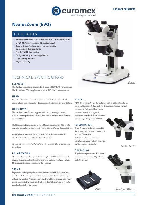
NexiusZoom 立体显微镜产品说明书

•NexiusZoom EVO ENZ-5313•ENZ-5302 / ENZ-5303the growth of unwanted microbes that can cause degradation, discoloration,•ENZ-1902-AP•ENZ-9505450360º| M A T E R I A L S S C I E N C E || L I F E S C I E N C E || E D U C A T I O N |S TA N D• E rgonomic pillar or rack & pinion stand with 3W incident and 3W transmitted LED illuminations (-P and -S stands)• E rgonomic pillar stand with two 3W goose-neck type incident LED illuminations on each side and a 3W transmitted LED illumination (-PG stand)• Ergonomic pillar stand with rotating mirror and 3W LED transmitted and incident illuminations (-M stand)• E rgonomic designed universal or boom stands, without illumination (-U, -B and BC stands)• Articulated arm stand for table mounting or with heavy desktop stand, both without head holder, without illumination (-A and -AP stands)All pillar and rack & pinion stands are supplied with two object clamps. Alloy metal cast, hardened coatingS TAG E180 x 155mm X-Y mechanical stage with 76 x 55mm translation stage and transparent glass plate for NexiusZoom, fixed on stage of microscope. Onlyavailable with new microscopes (due to fixing), so it has to be ordered with the purchase of a microscope (See picture: ENZ-9505)I L L U M I N AT I O N3 W transmitted and incident LED illuminators with internal power supply 100-240 V. Both illuminators can be used simultaneously and the light intensities can be adjusted separately. The universal single or double arm stands and the articulated stands can be equipped with the ring illuminatorsELE-1974 and ELE-1973 with respectively 72 or 144 power LEDs controlled in segments, ideal for creating or lifting shadesE S For inspection and assembly applications. Electrostatic discharge (ESD) is the unwanted sudden flow of electricity between two electrically charged objects. ESD can cause a range of harmful effects as well as permanent damage to solid state electronics componentsEuromex therefore introduces electrostatic protected microscopes in the NexiusZoom range. The body and stand of the microscope are coated with a special static dissipative paint eliminating harmful electrostatic discharges making the microscopes suitable for all static-sensitive environmentsPAC Supplied with power cord, dust cover, a spare fuse and user manual. All packed in a polystyrene box™25639346339103180178220259.5310.5| M A T E R I A L S S C I E N C E | | L I F E S C I E N C E |PROD UC T DATAS HEE T| E D U C A T I O N |N E X I U S Z O O M 0.67- 4.5 (W F 10X /22M M )M O D E L SBinoTrinoPillar stand (-P)Rack & pinion stand (-S)Universal stand (-U)Boom standon heavy base plate (-B)Boom stand on table clamp (-BC)Articulated arm stand on table clamp (-A)Articulated arm stand on heavy base plate (-AP)Gooseneck dual LED (-PG)Mirror LED (-M)Weight (kg)ENZ-1902-P •• 5.0ENZ-1902-PG •••5.1ENZ-1902-M •••4.9ENZ-1902-S ••4.9ENZ-1902-U ••15.6ENZ-1902-B ••22.1ENZ-1902-BC ••10.5ENZ-1902-A ••8.6ENZ-1902-AP ••20.7ENZ-1903-P •• 5.2ENZ-1903-PG •••5.3ENZ-1903-M •••5.1ENZ-1903-S ••5.1ENZ-1903-U ••15.7ENZ-1903-B ••22.2ENZ-1903-BC ••10.6ENZ-1903-A ••8.7ENZ-1903-AP••20.8M O D E L SBinoTrinoPillar stand (-P)Rack & pinion stand (-S)Universal stand (-U)Boom stand on base plate(-B)Boom stand on table clamp(-BC)Articulated arm stand on table clamp (-A)Articulated arm stand on base plate (-AP)Gooseneck dual LED (-PG)Mirror LED (-M)Weight (kg)ENZ-1702-P•• 5.0ENZ-1702-PG•••5.1ENZ-1702-M•••4.9ENZ-1702-S•• 4.9ENZ-1702-U••15.6ENZ-1702-B••22.1ENZ-1702-BC••10.5ENZ-1702-A••8.6ENZ-1702-AP••20.7ENZ-1703-P•• 5.2ENZ-1703-PG•••5.3ENZ-1703-M•••5.1ENZ-1703-S•• 5.1ENZ-1703-U••15.7ENZ-1703-B••22.2ENZ-1703-BC••10.6ENZ-1703-A••8.7ENZ-1703-AP••20.8N E X I U S Z O O M E V O 0.65-5.5 (W F 10X /23M M )D I M E N S I O N SThe NexiusZoom EVO models are now equipped with click-stopsENZ-8903 ENZ-8904 ENZ-8905 ENZ-8907 ENZ-8915 ENZ-8920 C O M PAT I B I L TA B L E AU X I L I Y L E N S E SM O D E L S0.3x Magnification0.4x Magnification0.5x Magnification0.75x Magnification 1.5x Magnification2x Magnification ENZ-9000/9005•••NexiusZoom-P, -M, -PG•••NexiusZoom-P-ESD•••NexiusZoom-S•NexiusZoom-S-ESD•••ENZ-1903-B•ENZ-1902-BC•ENZ-1903-S•ENZ-1902-M•ENZ-1902-PG•ENZ-1902-P•ENZ-1902-U• ENZ-1903-U-ESD• ENZ-1903-B-ESD• ENZ-1903-P-ESD• ENZ-1903-S-ESD•ENZ-9005•ENZ-9000•ENZ-9095ead 76 mm holder for NZENZ-9000 / 9005 / 9015 models availableAUXILIARY LENSES*The ELE-5212 in two different configurations EuromexMicroscopenbv•Papenkamp20•6836BDArnhem•TheNetherlands•T+31(0)263232211•****************•。
大鼠立体定向仪使用说明
大鼠立体定向仪使用说明一、简介大鼠立体定向仪是一种用于在实验中精确定位大鼠脑部区域的仪器。
它通过空间坐标和解剖结构来确定目标区域,为实验操作提供准确的参考。
本文将详细介绍大鼠立体定向仪的使用方法和注意事项。
二、使用方法1. 准备工作确保大鼠立体定向仪处于正常工作状态。
检查各个部件是否完好,并连接好相应的电源和电缆。
然后,选择适当的麻醉药物和镇痛药物,将大鼠进行麻醉和固定,使其处于稳定的状态。
2. 定位大鼠头部将大鼠放置在大鼠立体定向仪的创口台上,用耳机将大鼠的头部固定住。
确保大鼠的头颅稳定且不会移动。
调整创口台的高度和角度,使其与大鼠头部的位置和姿态相匹配。
通过调节头部固定装置,确保大鼠的头部能够自由移动。
3. 定位大鼠脑部区域使用大鼠立体定向仪的刻度尺,测量大鼠头部的尺寸和相对位置。
根据实验需求,确定目标区域的坐标和深度。
根据测量结果,调整大鼠立体定向仪的坐标轴,使其与目标区域的坐标轴对齐。
确保坐标轴的调整准确无误。
4. 实施实验操作根据实验协议,选择合适的手术器械,进行实验操作。
根据大鼠立体定向仪提供的坐标和深度信息,准确地定位目标区域。
在实施实验操作过程中,注意保持操作环境的清洁和无菌。
遵循实验操作规范,确保操作的准确性和安全性。
三、注意事项1. 在使用大鼠立体定向仪之前,应详细阅读使用说明书,并按照说明书的要求进行操作。
2. 在操作过程中,应注意保持操作环境的无菌和清洁,以避免感染和交叉污染。
3. 在固定大鼠头部时,应注意不要过紧或过松,以避免对大鼠造成不适或伤害。
4. 在调整大鼠立体定向仪的坐标轴时,应小心操作,确保准确无误。
5. 在实施实验操作时,应注意操作的轻柔和准确性,以避免对大鼠脑部造成损伤。
6. 在实验操作完成后,应及时清理和消毒大鼠立体定向仪,以确保下次使用时的卫生和安全。
四、总结大鼠立体定向仪是一种在实验中定位大鼠脑部区域的重要工具。
正确使用大鼠立体定向仪可以提高实验操作的准确性和可靠性。
三维说明书
2.2.3计算机使用注意事项
计算机采用高级软件管理整个系统的工作。由于主机工作状态复杂、数据量大,计算机负担较重,故对用作工作站的计算机绝对不能作为一般计算机使用,更不能当作游戏机取乐。否则一旦引进病毒,后果不堪设想,而由此造成的损失,即使在保证期内本公司也不予负责。
点击“选择控件”,出现如下界面:
选择“MSFLXGRD.OCX”,并打开,再点击“注册控件”,出现以下界面即为注册成功。
再次点击“选择控件”,重复上述过程,注册“olch2x8.ocx、olch3x8.ocx、TeeChart5.ocx”。
5.4.从开始菜单里运行“OFA_3DI”软件,出现注册界面,根据安装光盘里的“安装序列号.txt”中的用户名和授权密码输入即可使用。
5.软件的安装
5.1.双击 跳出窗口
按“OK”键,进入下面界面:
点击图中的“Change Directory”,可选择需要的路径安装;如果要默认路径安装,点击图中的 图标开始安装。
选择在开始菜单中的组,按“Continue”开始默认安装。
在安装过程中,出现如下提示,则点击“忽略”,继续安装。
点击“确定”,安装完毕。
图31
弹出如下窗口:
图32
选择参数设置弹出如下窗口:
图33
选择三维扫描,设置好扫描范围的EX和EM波长的范围,设置扫描步长,设置好后
选择确定,返回图谱扫描窗口,然后选择样品扫描,此时会弹出如下窗口:
图34
此时的图形采集窗口正在接受采集信息,扫描后窗口显示:
图35
图谱类型:在窗口设置项中,可选择三维图和等值图(如图36);
医疗器械行业中的3D打印技术使用教程
医疗器械行业中的3D打印技术使用教程随着科技的不断进步,3D打印技术在各个领域取得了重大突破,医疗器械行业也不例外。
3D打印技术的应用为医疗器械的设计与制造提供了全新的方法和可能性。
本文将为您介绍医疗器械行业中的3D打印技术使用教程,包括技术原理、应用案例和制造流程等方面的内容。
1. 技术原理3D打印技术,即三维打印技术,是一种通过逐层叠加材料来构建物体的制造方法。
在医疗器械行业中,使用的材料通常是生物相容性材料,能够满足患者的健康安全需求。
具体的技术原理包括以下几个步骤:(1)建模:首先,需要通过计算机辅助设计软件(CAD)进行建模,设计出需要制造的医疗器械的三维模型。
(2)切片:将三维模型分割为一系列的薄片,每个薄片都代表了打印机每一层的独立打印路径。
(3)打印:选择合适的3D打印机和材料,按照切片得到的路径信息逐层打印,叠加成完整的物体。
(4)后处理:制造完成后,可能需要进行除支撑结构、清洁、烘干等后续处理步骤,以便得到最终的医疗器械。
2. 应用案例3D打印技术在医疗器械行业中的应用案例丰富多样,以下是其中的一些典型案例:(1)手术模型:通过3D打印技术,可以制造出精确的手术模型,供医生进行手术前的培训和预演。
手术模型可以根据患者的具体情况进行定制,提高手术精确度和安全性。
(2)义肢和矫形器具:3D打印技术可以根据患者的个体特征制造出定制化的义肢和矫形器具,提供更好的适配性和舒适度,改善患者生活质量。
(3)器官模型:通过3D打印技术,医生可以获得患者的器官模型,用于进行手术规划、教学和病情沟通。
器官模型可以准确还原患者的解剖结构,帮助医生更好地了解病情和手术难度。
(4)手术辅助工具:医疗器械行业中的一些手术辅助工具,如手术导板、定位器等,可以通过3D打印技术进行制造。
这样可以根据患者的个体差异提供个性化的解决方案,提高手术效果和患者体验。
(5)药物制剂:在医疗器械行业中,3D打印技术也被应用于药物制剂领域。
科学实验室用三体光学仪器说明书
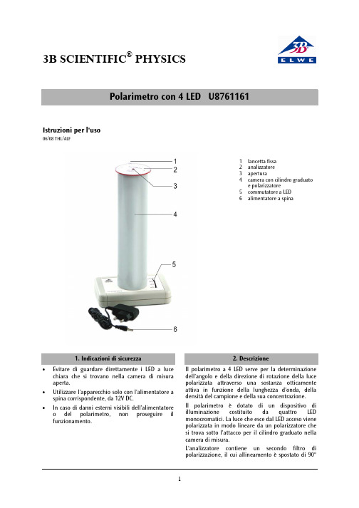
3B SCIENTIFIC ®PHYSICSPolarimetro con 4 LED U8761161Istruzioni per l'uso06/08 THL/ALF1 lancetta fissa2 analizzatore3 apertura4 camera con cilindro graduatoe polarizzatore 5 commutatore a LED 6 alimentatore a spina1. Indicazioni di sicurezza•Evitare di guardare direttamente i LED a luce chiara che si trovano nella camera di misura aperta.• Utilizzare l’apparecchio solo con l’alimentatore a spina corrispondente, da 12V DC.•In caso di danni esterni visibili dell’alimentatore o del polarimetro, non proseguire il funzionamento.2. DescrizioneIl polarimetro a 4 LED serve per la determinazione dell’angolo e della direzione di rotazione della luce polarizzata attraverso una sostanza otticamente attiva in funzione della lunghezza d’onda, della densità del campione e della sua concentrazione.Il polarimetro è dotato di un dispositivo di illuminazione costituito da quattro LED monocromatici. La luce che esce dal LED acceso viene polarizzata in modo lineare da un polarizzatore che si trova sotto l’attacco per il cilindro graduato nella camera di misura.L’analizzatore contiene un secondo filtro di polarizzazione, il cui allineamento è spostato di 90°•Fornire corrente mediante l’alimentatore a spina.•Scegliere la lunghezza d’onda spostando il commutatore a LED.La misurazione dell’angolo di polarizzazione della sostanza ottica attiva avviene mediante rotazione precisa dell’analizzatore, osservando il punto fluorescente dall’apposita apertura. 100 ml di liquido nel cilindro graduato corrispondono ad uno spessore dello strato di 1, 9 dm, 75 ml – 1,43 dm, 50 ml – 0,96 dm e 25 ml – 0,44 dm.•Misurare l’angolo di rotazione dei diversi LED. •Nella fase successiva, ridurre, con la stessaconcentrazione, lo spessore dello strato a 1,43dm (75 ml) e ripetere la misurazione.Elwe Didactic GmbH • Steinfelsstr. 6 • 08248 Klingenthal • Germania • 3B Scientific GmbH • Rudorffweg 8 • 21031 Amburgo ▪ Germania • Con riserva di modifiche tecniche •Eseguire altre misurazioni con spessori dello strato di 0,96 dm (50 ml) e 0,44 dm (25 ml).•Quindi preparare le soluzioni zuccherine (20 g, 30 g e 40 g in 100 ml) e misurare l’angolo di rotazione in modo analogo alla prima serie di misurazioni.•Inserire i valori rilevati in una tabella e rappresentare graficamente per ogni colore l’angolo di rotazione in funzione della concentrazione e dello spessore dello strato.6.2 Determinazione de l l ’ango l o di rotazionespecifico del saccarosioL’angolo di rotazione specifico []α è una costantedella sostanza e risulta dalla seguente equazione,con lunghezza d’onda nota della luce λ e temperatura T :[]lc T⋅α=αλ (1)α = angolo di rotazione misurato c = concentrazione c della sostanza discioltal = spessore dello strato della soluzioneI dati contenuti nella letteratura si riferiscono per la maggior parte alla linea D gialla del sodio (λ =589 nm) e ad una temperatura di 20°C.• Preparare una soluzione zuccherina (50 g in 100ml). Pesare a tale scopo 10 g di zucchero, scioglierlo in ca. 60 cm 3di acqua distillata e introdurlo nel cilindro graduato fino a 100 cm 3. • Misurare lo spessore dello strato e inserire il cilindro graduato nella camera di misura. • Determinare l’angolo di rotazione con luce gialla. • Calcolare l’angolo di rotazione specifico in baseall’equazione 1 e confrontarlo con il valore di letteratura. Valori di letteratura per l’angolo di rotazione specifico []20D α Saccarosio +66,5°, D-glucosio D +52,7°, D-fruttosio -92,4°. (Valori estrapolati da Aebi, Einführung in die praktische Biochemie, Karger 1982)6.3 Inversione di saccarosioMediante acido è possibile scindere il saccarosio in D-glucosio e D-fruttosio. Durante questa operazione, entrambi i componenti si liberano in ugual misura. La rotazione destra si riduce sino a che l’angolo di rotazione diventa negativo. Tale operazione viene definita inversione. La miscela di glucosio-fruttosio viene denominata pertanto zucchero invertito ed è ad es. un componente del miele artificiale.• Preparare una soluzione zuccherina (30 g in 100ml). Pesare a tale scopo 30 g di zucchero e scioglierlo in ca. 60 cm 3 di acqua distillata (50° C). • Aggiungere con cautela (utilizzare occhiali diprotezione) 15 ml di acido cloridrico al 25 %.• Introdurre la soluzione nel cilindro graduato fino a 100 cm 3e inserirlo nella camera di misura. • Attivare immediatamente un cronometro edeterminare l’angolo di rotazione. • Ad intervalli di 5 minuti, misurare di nuovol’angolo di rotazione e annotare tutti i valorimisurati in una tabella. • Dopo 30 minuti terminare la serie di misurazioni e disegnare la curva d’inversione. 6.4 Misurazione de l l a concentrazione con un ango l o di rotazione specifico su l l a base dell’esempio del saccarosio nella Cola • Riempire il cilindro graduato con 100 ml di Cola.• Determinare l’angolo e la direzione di rotazione con l’ausilio del diodo giallo. • Calcolare il contenuto di zucchero invertendol’equazione 1. []l c ⋅αα= ⎥⎦⎤⎢⎣⎡3cm g。
3D显微镜设备操作说明书
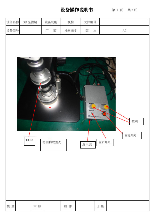
待测物放置处设备操作说明书 第 1 页 共2页设备名称 3D 显微镜设备功能 视检 文件编号 设备型号厂 商桂林光学版 本A0核 准 审 核 制 作日 期旋转开关左右开关总电源微调CCD设备操作说明书第2 页共2页设备名称3D顯微鏡设备功能視檢文件编号设备型号厂商桂林光學版本一、操作說明1、接入相机:打开AMCAP软件选择菜单栏“设备”选定“USB 视频设备”,(如果电脑内置也有摄像头需选第二个USB 视频设备),再在“选项”中选择“预览”就可以看到图像进行观察了。
2、录像功能:选择菜单“文件”选项---Set capture files~~给录像的文件选择存储路径及命名后点击“打开”在弹出的窗口中对“Create a new capture file”打钩后“确定”就可以在菜单选项栏中选择“捕捉”---“开始捕捉”在弹出的窗口点“OK”再同样的选项中选择“停止捕捉”就完成整个摄像过程。
3、拍照功能:先在“捕捉”选项中选择“静态图片”---“设置默认路径”选好图片存储的保存位置“确定后”就可以直接点击菜单选项中“拍照”就可以进行拍照了。
还可以在“捕捉”---“静态图片”中选择“高分辨率”拍照及图片格式等。
4、色彩调节:在菜单栏“选项”中选择“vid eo capture filter…”在弹出窗口中可以进行色彩的调节,如果色彩调乱可以点击在下面的“默认值”进行色彩还原。
5、分辨率设置:在菜单栏“选项”中选择“video capture pin…”在弹出窗口中的“输出大小”栏中可以选择相应的分辨率,一般选择640*480.分辨率越大拍摄效果越清晰但帧速就会越慢存储空间会越大二、操作前的注意事项1.显微镜是一种精密的仪器设备,使用时必须避免在运输或使用过程中突然移动或碰撞。
2、避免阳光直射、高温、潮湿、灰尘或震动。
3、避免在透镜表面留下污垢或手印,脏的镜片将降低图像的清晰度。
核准审核制作日期。
NexiusZoom (EVO)立体显微镜产品说明书
NZ.1903-SBinocularTrinocularPillar standRack & pinion standUniversal standBoom standArticulated arm standWeight (kg)NZ.1702-P ••5.0NZ.1702-S ••4.9NZ.1702-U ••15.6NZ.1702-B ••22.1NZ.1702-A ••8.6NZ.1703-P ••5.2NZ.1703-S ••5.1NZ.1703-U ••15.7NZ.1703-B ••22.2NZ.1703-A••8.7M O D E L S N E X I U S Z O O M E V O 0.65-5.5 (W F10X /23M M )BinocularTrinocularPillar standRack & pinion standUniversal standBoom standArticulated arm standWeight(kg)NZ.1902-P ••5.0NZ.1902-S ••4.9NZ.1902-U ••15.6NZ.1902-B ••22.1NZ.1902-A ••8.6NZ.1903-P ••5.2NZ.1903-S ••5.1NZ.1903-U ••15.7NZ.1903-B ••22.2NZ.1903-A••8.7M O D E L S N E X I U S Z O O M 0.67-4.5 (W F10X /22M M )M AG N I F I C AT I O N SNexiusZoom standard & ESD Working distance and field of view with standard HWF 10x / 22 High Wide Field eyepiecesZoom indicationObjective 1x (standard)Working distance 110 mm Auxiliary lens 0.5x Working distance 165 mm Auxiliary lens 0.75x Working distance 120 mm Auxiliary lens 1.5x Working distance 45 mm Auxiliary lens 2x Working distance 30 mm TotalMagnificationsField of view in mmTotalMagnificationsField of view in mmTotalMagnificationsField of view in mmTotalMagnificationsField of view in mmTotalMagnificationsField of view in mm0.67 6.732.8 3.3565.7 5.043.810.121.913.416.40.77.031.4 3.562.9 5.341.910.521.014.015.70.88.027.5 4.055.0 6.036.712.018.316.013.81.010.022.0 5.044.07.529.315.014.720.011.01.515.014.77.529.311.319.622.59.830.07.32.020.011.010.022.015.014.730.07.340.0 5.53.030.07.315.014.722.59.845.0 4.960.0 3.74.040.0 5.520.011.030.07.360.0 3.780.0 2.84.545.04.922.59.833.86.567.53.390.02.4NexiusZoom EVO Working distance and field of view with standard HWF 10x / 23 High Wide Field eyepiecesZoom indicationObjective 1x (standard)Working distance 110 mm Auxiliary lens 0.5x Working distance 165 mm Auxiliary lens 0.75x Working distance 120 mm Auxiliary lens 1.5x Working distance 45 mm Auxiliary lens 2x Working distance 30 mm TotalMagnificationsField of view in mmTotalMagnificationsField of view in mmTotalMagnificationsField of view in mmTotalMagnificationsField of view in mmTotalMagnificationsField of view in mm0.65 6.535.4 3.2570.8 4.947.29.823.613.017.70.77.032.9 3.565.7 5.343.410.521.914.016.40.88.028.8 4.057.5 6.038.312.019.216.014.41.010.023.0 5.046.07.530.715.015.320.011.51.515.015.37.530.711.320.422.510.230.07.72.020.011.510.023.015.015.330.07.740.0 5.83.030.07.715.015.322.510.245.0 5.160.0 3.84.040.0 5.820.011.530.07.760.0 3.880.0 2..94.545.0 5.122.510.233.8 6.867.5 3.490.0 2.65.555.04.227.58.441.35.682.52.81102.1NZ.1902-UNZ.1902-P100330 450360º360º340º310max1.000 maxFrom 0 to 295 max40NZ.1902-ANZ.1903-BNZ.1902-SNZ.1903-P-ESDNZ.1903-U-ESDNZ.1903-P-ESDE S D S AF E M O D E L SBinocularTrinocularPillar standRack & pinion standUniversal standBoom standArticulated armstandAntistatic ESDWeight (kg)NZ.1902-P-ESD ••• 5.0NZ.1902-S-ESD ••• 4.9NZ.1902-U-ESD •••15.6NZ.1902-B-ESD •••22.1NZ.1903-P-ESD ••• 5.3NZ.1903-S-ESD •••5.1NZ.1903-U-ESD •••15.7NZ.1903-B-ESD•••22.2NexiusZoom ESDEuromexMicroscopenbv•Papenkamp20•6836BDArnhem•TheNetherlands•T+31(0)263232211•F+31(0)263232833•****************•ACCE SS O R I E S A N D SPA R E PA R T SNZ.5302 NexiusZoom binocular head with eyepieces NZ.5303 NexiusZoom trinocular head with eyepieces NZ.5312 NexiusZoom EVO binocular head with eyepieces NZ.5313 NexiusZoom EVO trinocular head with eyepieces NZ.6010 Pair of HWF 10x / 22 mm eyepieces NZ.6015 Pair of HWF 15x / 16 mm eyepieces NZ.6020 Pair of HWF 20x / 12 mm eyepiecesNZ.6110 HWF 10x / 22 mm eyepiece with micrometerNZ.6210 Pair of HWF 10x / 23 mm eyepieces (only suitable for the EVO)NZ.6099 Pair of eyecupsNZ.8903 A uxiliary lens 0.3x (not suitable for NZ.1902-S, NZ.1903-S, NZ.1902-S-ESD and NZ.1903-S-ESD)NZ.8905 A uxiliary lens 0.5x. Working distance 165 mm (not suitable forNZ.1902-S and NZ.1903-S)NZ.8907 Auxiliary lens 0.75x. Working distance 120 mm NZ.8915 Auxiliary lens 1.5x. Working distance 45 mmNZ.8920 A uxiliary lens 2.0x. Working distance 30 mm (not suitable forNZ.1902-S and NZ.1903-S)NZ.8950 Protection glass for NexiusZoom headNZ.9010 E rgonomic rack & pinion stand with transmitted and incident LEDilluminatorsNZ.9015 E rgonomic pillar stand with transmitted and incident LEDilluminatorsNZ.9020 Universal (single arm) stand without NexiusZoom head holder NZ.9030 Boom (double arm) stand without NexiusZoom head holder NZ.9090 NexiusZoom head holder (for NZ.9020 and NZ. 9030)NZ.9025 A rticulated arm stand with table clamp |(without NexiusZoomhead holder)NZ.9027 A rticulated arm stand with heavy stand (without NexiusZoomhead holder)NZ.9081 NexiusZoom head holder (for articulated arm stand NZ.9025)NZ.9520 P olarization kit for NexiusZoom: 360° rotatable round stage withbuilt-in polarization filter (NZ.9524) + analyzer in mount to be screwed under head (NZ.9525)NZ.9524 360° rotatable round stage with built-in polarization filter forNexiusZoomNZ.9525 360° rotatable analyser in mount to be screwed under head ofNexiusZoomAE.5168-NZ Heating stage with PID controller up to 50oC NZ.9950 Standard opaque stage plate NZ.9956 Black/white stage plate NZ.9570 Pair of object clamps for stageNZ.9572 Adjustable GEM object clamp for NexiusZoom (EVO)NZ.9833 C -mount adapter with 0.33x lens for 1/3” cameras (suitable fortrinocular models)NZ.9850 C -mount adapter with 0.5x lens for 1/2” cameras (suitable fortrinocular models)50.876 Dark field attachmentAE.5130 U niversal SLR camera adapter with 2x projection lens for23.2 mm tubes. Need T2 adapterAE.5025 T2 adapter for Nikon D digital SLR camerasAE.5040 T 2 adapter for Canon EOS digital SLR camerasOther T2 adapterson requestLE.1974 R ing illuminator with 72 LEDs with adjustable light intensity.External mains adapter 100-240 V. With segment controller. Brightness of 21.000 Lux at height of 100 mm and color temperature of 6.500K. Mounting diameter between 25-61 mmLE.1973 R ing illuminator with 144 LEDs with adjustable light intensity.External mains adapter 100-240 V. With segment controller. Brightness of 23.000 Lux at height of 100 mm and color temperature of 6.500K. Mounting diameter between 25-61 mmAE.1112 O bject micrometer 50 mm (divided in 500 parts on glass slide76 x 26 mm)。
科学实验室用 3B 科学实验 力学实验器械说明书

3B SCIENTIFIC ® PHYSICS1Braccio di leva 1008539Manuale di istruzioni01/13 ALF1 Base di supporto2 Asta di supporto3 Scala4 Indicatore5 Pesi6 Supporto con cuscinetto asfere e dado zigrinato 7 Braccio di leva1. DescrizioneKit per la dimostrazione delle leggi sulle leve, per esperimenti sull’equilibrio e come modello di una bilancia a braccio.Il kit leve è costituito da un supporto sul quale è montato un braccio di leva su un cuscinetto a sfere. Al centro dell’asse longitudinale del brac-cio di leva sono presenti fori per la regolazione del punto di rotazione, e per agganciarvi i pesi. Una scala a blocchi bianca e rossa permette la rapida lettura della lunghezza dei bracci di leva. Una scala fissata al supporto e dotata di indica-tore permette le visualizzazione precisa dello stato di equilibrio.2. Caratteristiche tecnicheLunghezza del braccio di leva: 1 mMassa del braccio di leva: 0,458 kg Numero dei fori: 21 Distanza tra i fori: 50 mm Set di pesi:10x 50 g.3. Principio di funzionamentoLa leva appartiene alla famiglia delle machine semplici. Per lo più si tratta di un’asta diritta o angolata, che può essere ruotata intorno a un asse e sulla quale, al di fuori dell’asse di rotazi-one, hanno effetto le forze.Ogni forza determina una rotazione, la cui po-tenza è proporzionale all’intensità della forza e alla distanza dalla linea di azione della forza rispetto all’asse di rotazione (lunghezza del braccio di leva). La leva con l’asse di rotazione nel punto O, sul quale hanno effetto le forze F e G , si trova in equilibrio, se il momento torcente di sinistra corrisponde al momento torcente di destra (legge sulle leve: forza per braccio di forza uguale a carico per braccio di carico). Per le forze F , G e i bracci di leva L 1, L 2 vale: 21L F L G ⋅=⋅Se il punto di rotazione della leva si trova tra I punti di applicazione delle due forze, si parla di leva a due bracci (Fig. 2), se le forze si trovano sullo stesso lato, si parla di leva a un braccio (Fig. 3).3B Scientific GmbH ▪ Rudorffweg 8 ▪ 21031 Amburgo ▪ Germania ▪ Con riserva di modifiche tecniche © Copyright 2013 3B Scientific GmbH4. Comandi4.1 Assemblaggio dell’apparecchio •Far scorrere il supporto della scala e la sca-la fino al centro dell’asta di supporto e fis-sare con la vite.• Posizionare l’asta di supporto sulla base disupporto e fissare con la vite. • Montare il supporto con cuscinetto a sferesull’asta di supporto e serrare con la vite. • Applicare l’indicatore sul braccio di leva. •Con il dado zigrinato fissare il braccio di leva con l’indicatore sull’alloggiamento del brac-cio di leva.• Regolare la scala in modo tale chel’estremità dell’indicatore si trovi in corris-pondenza del bordo inferiore degli indici della scala. • Far scorrere l‘elemento di livellamento sulbraccio di leva e quindi portare in equilibrio il braccio di leva.Fig. 1 Assemblaggio della leva5. Misure sperimentali5.1 Conferma della legge sulle leve con laleva a due bracci • Fissare il braccio a leva al centro del cus-cinetto a sfere. • Agganciare 5 pesi da 50 g (circa 2,5 N) sullato di sinistra del braccio di leva nel 3° foro a partire dal centro. • Agganciare 3 pesi da 50 g (circa 1,5 N) sullato di destra del braccio di leva nel 5° foro a partire dal centro. La leva è in equilibrio.• Ripetere l’esperimento con altre combinazi-oni di pesi.Fig. 2 Leva a due bracci5.2 Conferma della legge sulle leve con laleva a un braccio Altri apparecchi necessari:per ogni dinamometro 2 N, 5 N e 10 N (ad es. 1003105/1003106/100317)• Fissare il braccio di leva nell’ultimo foro delcuscinetto a sfere. • Agganciare 5 pesi da 50 g (circa 2,5 N) sullato di destra del braccio di leva nel punto della forza G . • Applicare un dinamometro nel punto dellaforza F . • Portare in equilibrio la leva e segnare laforza sul dinamometro.Durante questo esperimento osservare il peso del braccio di leva (0,458 kg corrisponde a 4,49 N).Fig. 3 Leva a un braccio。
来高科技三维扫描仪操作手册说明书
三维扫描仪使用手册来高科技(天津)有限公司目录第一章简介 (1)1.1三维扫描仪简介 (1)1.2公司简介 (1)1.3软件版权声明 (2)1.4三维扫描仪安全注意事项 (3)1.5三维扫描仪独特功能介绍 (4)1.6 概念、名词解释 (7)1.7 免责声明 (7)1.8 安全警告 (8)第二章操作说明 (9)2.1 推荐电脑配置 (9)2.2 线束连接方法 (9)2.3 软件安装 (10)2.4 扫描仪幅面调节 (21)2.5标定 (23)2.6 扫描前准备工作 (33)2.7 点云采集、处理及导出 (34)第三章界面功能介绍 (40)3.1工作界面 (40)3.2文件菜单 (41)3.3标定菜单 (44)3.4采集菜单 (45)3.6拼接菜单 (48)3.7工具菜单 (49)3.8 视图菜单 (58)3.9 帮助菜单 (59)第四章常见问题解答 (61)4.1 软件打不开 (61)4.2 光机不亮 (61)4.3 光机亮,但不能投射光栅 (61)4.4 相机打不开 (62)4.5 不能识别标记点 (62)4.6 采集不到点云 (62)4.7 点云拼接不上 (63)4.8 点云数据不好 (63)4.9 机器经常需要标定 (63)4.10 标定不成功 (63)第一章简介1.1三维扫描仪简介三维扫描仪,也称为三维立体扫描仪,3D扫描仪,是融合光、机、电和计算机技术于一体的高科技产品,主要用于获取物体外表面的三维坐标及物体的三维数字化模型。
该设备不但可用于产品的逆向工程、三维检测等领域,而且随着三维扫描技术的不断深入发展,诸如三维影视动画、数字化展览馆、服装量身定制、计算机虚拟现实仿真与可视化等越来越多的行业也开始应用三维扫描仪这一便捷的手段来创建实物的数字化模型。
通过三维扫描仪非接触扫描实物模型,得到实物表面精确的三维点云数据,最终生成实物的数字模型,不仅速度快,而且精度高,几乎可以完美的复制现实世界中的任何物体,以数字化的形式逼真的重现现实世界。
教育行业仪器器材使用方法说明书
教育行业仪器器材使用方法说明书使用教育行业仪器器材的方法说明书第一部分:引言教育行业仪器器材在学校教学过程中起到了至关重要的作用。
正确使用这些仪器和设备,不仅可以提高教学效果,还可以确保教师和学生的安全。
本说明书旨在向教育工作者和学生介绍教育行业仪器器材的正确使用方法,以确保教学过程的顺利进行。
第二部分:安全须知在使用教育行业仪器器材之前,请仔细阅读以下安全须知,并严格遵守:1. 所有仪器器材必须经过专业人员检查和维护后方可使用。
2. 在使用仪器器材前,请仔细阅读使用手册和操作指南。
3. 在教学过程中,请确保学生们了解并遵守相应的安全规则。
4. 使用仪器器材时,应保证周围环境整洁干净,并确保足够的工作空间。
5. 操作仪器时,请务必使用个人防护装备,如手套、护目镜等。
第三部分:常见教育行业仪器器材的使用方法本节将介绍一些教育行业常见仪器器材的使用方法,包括但不限于投影仪、实验室仪器和音响设备。
1. 投影仪投影仪是教室中常用的教学工具,用于投影图像或视频,以便全班学生能够清晰地观看。
(1)确保投影仪与电源连接良好,并使用遥控器或面板上的按钮开启投影仪。
(2)根据需求选择正确的投影源,如电脑、DVD等,并用相应连接线将其与投影仪连接。
(3)调整投影画面的焦距、亮度和对比度,以确保图像清晰可见。
2. 实验室仪器实验室仪器在科学实验教学中起到了关键作用,包括显微镜、天平和试管架等。
(1)在使用实验室仪器之前,先阅读操作指南,并确保仪器处于良好的工作状态。
(2)使用显微镜时,请注意调整镜头,以获得清晰的观察效果。
(3)使用天平时,请确保放置物体稳定,并在读数前清零。
(4)使用试管架或其他支架时,请确保其稳固,并避免超载。
3. 音响设备音响设备在教育场所中常用于进行演讲、音乐播放和其他活动。
(1)确保音响设备与电源连接良好,并打开主机电源。
(2)调整音量大小,以确保声音清晰而不失真。
(3)根据需求调整音频源,如CD、MP3等,并使用相应连接线将其与音响设备连接好。
【2020最新智库】MicroHite3D三次元中文操作手册

Micro-Hite3D手動三次元操作手冊操作手冊智允貿易股份有限企业Chi-YeungTrading.Co.,LTD臺北總企业:台北縣三重市重新路五段609巷8號10樓TEL:(02)2999-1578FAX:(02)2999-1578臺中分企业:台中市西屯區大有五街41號TEL:(04)2313-6946FAX:(04)2316-4938上海分企业:上海市閔行區滬閔路7886號(上海花園二期81-1號)TEL:(21)5493-8815~8FAX:(21)5493-5848深圳分企业:深圳市寶安區沙井鎮新橋村洋仔二路新橋豪苑TEL:(755)2727-2583FAX:(755)2727-1604E-mail:cy@Micro-Hite3D三次元中文操作手冊1.何謂CMM(CoordinateMeasuringMachine)三次元量床及基本概念:我們用座標系統的變化,來描述三次元量測機台的位移量。
座標系統是由一位法國的哲學家兼數學家,笛卡爾RenéDescartes于西元1600年代早期所發明。
讓我們知道一個工件上,三D幾何的元素跟元素之間的位置相關性。
簡單地說,三次元座標系統就像是一個立體的地圖,地圖的上緣由左到又標示著A、B、C、D…..等區分,地圖的左緣由上到下標示著1、2、3、4…..等區分再加上海拔高度的標示,這字母/數字/高度的結合就稱作為三座標,相對於此立體地圖來說,此三座標的結合就能清楚地于圖上顯示出所代表的位置點。
再舉例說明,于一個有大樓及街道的立體地圖,從火車站trainstation(你的起點)要徒步走到飯店RitzHotel(終點位置),你先沿著ELM街走,經過兩個街口走到Maple路右轉,于直走經過四個路口走到Oak路交叉口,走進大樓上三樓飯店位置。
再下圖中我們也可以用座標4-E-3來表示位置,這就是相當於三次元量床上用X、Y、Z三軸座標來表示位置。
于地圖上,此座標位置是獨一無二且非常清楚的。
立体纸模使用手册说明书

零件序号
凸折线 (虚线)
凹折线 (点划线)
粘贴处(绿色圆形记号) 同个零件内的粘合
粘贴处(蓝色圆形记号) 与其他零件粘合
粘贴(粉色箭头)
弯曲
实用技巧
剪切掉零件后,用与零件同样颜色的笔涂上纸的横 截面和纸签的话,成品会更加美观。 在粘贴之前完成折叠和弯曲的话 组装会更容易一些。 通过牙签等将胶水薄涂的话,会干得快一些 还能防止胶水的溢出。
立体纸模
使用手册
准备工具
模型纸(需有一定厚度) 胶水(需有良好速干性)·剪刀、裁纸刀 尺子 ·铅笔 ·镊子 ·牙签 尖锐物(不用的圆珠笔、小刀等)
符号说明
剪切线 (实线)
剪切线 (红色实线)
切部分
说明图
制作方法
在剪切组装零件前,同铅笔等在零件的背面写上零件的序号。 在折线上,沿着尺子用尖锐物(不用的圆珠笔、小刀等)加上纹路。 仔细沿剪切线将组装零件剪切下来。 按照序号组装好从(1)到(8)的零件后,从 1 开始按照顺序全部组装起来。
此为左侧的说明图。右侧同样按此组装。
请注意
除此目的外请不要使用本数据。 剪刀、裁纸刀和胶水等工具,请在幼儿的手触碰不到的地方使用。 在使用剪刀和裁纸刀时,请小心注意不要切伤手指。 因含有细小的零件,请注意不要误吞。 有窒息等危险的可能性。 请注意不要被纸的横截面和纸签伤到。
使用手册
科学实验室用三维立体观察仪说明书
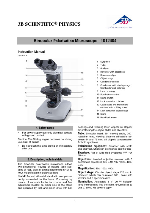
3B SCIENTIFIC ®PHYSICS1Binocular Polarisation Microscope 1012404Instruction Manual08/13 ALF1 Eyepiece2 Tube3 Analyser4 Revolver with objectives5 Specimen clips6 Object stage7 Condenser control8 Condensor with iris diaphragm,filter holder and polariser 9 Lamp housing 10 Illumination control 11 Mains switch12 Lock screw for polariser 13 Coarse and fine movementcontrols with holding brake 14 Lock screw for object stage 15 Stand16 Head lock screw1. Safety notes•For power supply use only electrical sockets with ground contact.Caution! The Stirling engine becomes hot during use. Risk of burns!• Do not touch the lamp during or immediatelyafter use.2. Description, technical dataThe binocular polarisation microscope allows two-dimensional viewing of objects (thin sec-tions of rock, plant or animal specimen) in 40x to 400x magnification in polarised light.Stand: Robust, all metal stand with arm perma-nently connected to the base. Focussing by means of separate knobs for coarse and fine adjustment located on either side of the stand and operated by rack and pinion drive with ballbearings and retaining lever, adjustable stopper for protecting the object slides and objective.Tube: Binocular head, 30° viewing angle, 360° rotatable head, viewing distance adjustable be-tween 54 and 75 mm, ±5 dioptric compensation for both eyepiecesPolarisation equipment: Polariser with scale and analyser, which can be inserted into the tube Eyepiece: Pair of wide field eyepieces WF 10x 18 mmObjectives: Inverted objective revolver with 3 achromatic objectives 4x / 0.10, 10x / 0.25, 40x / 0.65Magnification: 40x, 100x, 400xObject stage: Circular object stage 120 mm in diameter, which can be rotated 360°, scale with Vernier and 2 specimen clipsIllumination: Adjustable 6 V, 20 W halogen lamp incorporated into the base, universal 85 to 265 V, 50/60 Hz power supplyCondenser: Abbe condenser N.A.1.25 NA 0.65 with iris diaphragm , filter holder and blue filter, focussed via rack and pinion drive Dimensions: 240 x 190 x 425 mm³ approx. Weight: 6 kg approx.3. Unpacking and assemblyThe microscope is packed in a molded styro-foam container.•Take the container out of the carton remove the tape and carefully lift the top half off thecontainer. Be careful not to let the optical items (objectives and eyepieces) drop down. •To avoid condensation on the optical com-ponents, leave the microscope in the originalpacking to allow it to adjust to room tem-perature.•Using both hands (one around the pillar and one around the base), lift the microscope from the container and put it on a stable desk. •The objectives will be found within individual protective vials. Install the objectives into themicroscope nosepiece from the lowest magnification to the highest, in a clockwisedirection from the rear.•Put the head onto the top of the stand and tighten the head-lock-screw. Insert the eye-pieces into the tube.•Insert the analyser into the slot on the re-volving nosepiece.•Insert the condensor with polariser and tigh-ten the lock-screw.4. Operation4.1 General information•Set the microscope on a level table.•Place the object to be observed in the centre of the specimen stage. Use the clips to fas-ten it into place.•Connect the mains cable to the net and turn on the switch to get the object illuminated. •Make certain that the specimen is centered over the opening in the stage.•Adjust the interpupillary distance so that one circle of light can be seen.•Make the necessary eyepiece dioptre ad-justments to suit your eyes.•To obtain a high contrast, adjust the back-ground illumination by means of the iris dia-phragm and the variable illumination control. •Rotate the nosepiece until the objective with the lowest magnification is pointed at thespecimen. There is a definite “click” wheneach objective is lined up properly.NOTE: It is best to begin with the lowest power objective. This is important to reveal general structural details with the largest field of view first. Than you may increase the magnification as needed to reveal small details.To determine the magnification at which you are viewing a specimen, multiply the power of the eyepiece by the power of the objective.•Adjust the holding brake to give a suitable degree of tightness in the focusing mecha-nism.•Adjust the coarse-focusing-knob which moves the stage up until the specimen is fo-cused. Be careful that the objective does notmake contact with the slide at any time. Thismay cause damage to the objective and/orcrack your slide.•Adjust the fine-focusing-knob to get the im-age more sharp and more clear.•Colour filters may be inserted into the filter holder for definition of specimen parts.Swing the filter holder out and insert colourfilters.•Always turn off the light immediately after use.•Be careful not to spill any liquids on the mi-croscope.•Do not mishandle or impose unnecessary force on the microscope.•Do not wipe the optics with your hands.•Do not attempt to service the microscope yourself.4.2 Using the polarisation equipment•Insert the analyser into the slot on the re-volving nosepiece.•Rotate the polariser until the planes of the polariser and the analyser are exactly crossed,so that one sees a black background.Any object with a doubly-refracting (birefringent) structure should now appear brightly illuminated against the dark background. If that does not occur, it is possible that the direction of light vibration of the object coincides with the polari-sation direction. Whether or not that is the case can be tested by rotating the polariser or the specimen itself.A birefringent object, when rotated continuously, shows up brightly after each 90° rotation and is dark between these positions. In contrast, ob-jects that are isotropic and not birefringent re-main dark in all positions.23B Scientific GmbH • Rudorffweg 8 • 21031 Hamburg • Germany • Subject to technical amendments © Copyright 2013 3B Scientific GmbH4.3 Changing the lamp and fuse 4.3.1 Changing the lamp• Turn off the power switch, unplug the mainsplug and let the lamp cool down to avoid be-ing burnt.• For safety reasons, remove the eyepiece. • To change the lamp lay the microscope onits back to reach the lid on the bottom side. • Loosen screw C of the lamp socket andpush it outwards so that it is in the position shown in Fig.1.• Loosen screw A and open the cover.• To remove the halogen lamp, use a cloth orsimilar material. Do not touch the bulb with the bare hand.• Lift out the halogen lamp and replace it witha new one.• Close the cover and secure it with thescrew.• Push the lamp socket back into the originalposition and tighten screw C.CAFig. 1 Lamp socket cover: A - knurled screw, B - ven-tilation slots, C - securing screws of lamp-holder4.3.2 Changing the fuse• Turn off the power switch and unplug themains plug.• Unscrew the fuse holder on the back of thestand base with a screwdriver.• Replace the fuse and reinsert the holder inits socket.5. Storage, cleaning and disposal• Keep the microscope in a clean, dry and dust free place.• When not in use always cover the micro-scope with the dust cover.•Do not expose it to temperatures below 0°C and above 40°C and a max. relative humid-ity of over 85%.• Always unplug the mains plug before clean-ing or maintenance.• Do not clean the unit with volatile solvents or abrasive cleaners.• Do not disassemble objective or eyepieces to attempt to clean them.• Use a soft linen cloth and some ethanol to clean the microscope.• Use a soft lens tissue to clean the optics.• The packaging should be disposed of at local recycling points. •Should you need to dispose of the equip-ment itself, never throw it away in normal do-mestic waste. Local regulations for the dis-posal of electrical equipment will apply.。
科学 PHYSICS E5 三维显微镜说明书

3B SCIENTIFIC ®PHYSICSIstruzioni d’uso07/16 ALFI microscopi E5 consentono l’osservazione bidimensionale di oggetti (sezioni so ttili di piante o animali) con ingrandimento da 40 a 1000 volte.Oltre alla testa binoculare, il modello di microscopio TE5 offre la possibilità di collegare simultanea-mente una videocamera per documentazione fotografica e video dell'osservazione.1 Oculare2 Tubo3 Revolver portaobiettivi con obiettivi4 Tavolino portaoggetti con guida peroggetti 5 Condensatore con diaframma a iride eportafiltri 6 Illuminazione 7 Interruttore di rete 8 Testata 9 Stativo10 Azionamento coassiale del tavolinoportaoggetti 11 Freno di arresto12 Manopola per regolazione micrometrica 13 Manopola per regolazione macrometricaropor.∙Aprire con precauzione il contenitore una volta rimosso il nastro adesivo. Durante tale opera-zione prestare attenzione affinché i pezzi dell’ottica (obiettivi e oculari) non c adano.∙Per evitare la formazione di condensa sui componenti ottici lasciare il microscopio nella confezione finché non abbia raggiunto la temperatura ambiente.∙Estrarre il microscopio con entrambe le mani (una mano sul braccio dello stativo e una sul piede) e collocarlo su una superficie piana. ∙Gli obiettivi sono confezionati in piccole scato-le separate. Essi devono essere avvitati nelle aperture della piastra portarevolver in ordine progressivo, cominciando dal lato posteriore e in senso orario a partire dall’obiettivo con il fat-tore di ingrandimento minore fino a quello con l’ingrandimento maggiore.∙Quindi inserire l’oculare nel tubo e fissarlo con la chiave per viti a esagono cavo piccola. ∙Fissare la testata con la chiave per viti a esagono cavo grande. 3.1 Indicazioni generali∙Collocare il microscopio su un tavolo dalla superficie piana.∙Collocare l’oggetto da osservare al centro del tavolino portaoggetti.∙Collegare il cavo di rete e attivare l’illuminazione.∙Spostare il supporto portaoggetti sul percor-so dei raggi luminosi in modo che questi lo il-luminino chiaramente.∙Adattare agli occhi il potere diottrico (ved. 3.3). ∙Regolare la distanza interoculare finché non sarà visibile un unico cerchio luminoso (ved. 3.3).∙Per ottenere un contrasto elevato, regolare l’illuminazione posteriore attraverso il di a-framma ad iride.∙Ruotare l’obiettivo con l’ingrandimento m ini-mo fino a portarlo sul percorso dei raggi lu-minosi. Il raggiungimento della corretta posi-zione viene segnalato dallo scatto dell’obiettivo.Nota:È opportuno cominciare con l’ingrandimento minim o per poter riconoscere dapprima i dettagli macroscopici delle strutture. Il passaggio a fattori di ingrandimento maggioriavviene attraverso la rotazione del revolver fino all’inserimento dell’obiettivo d esiderato.Il valore di ingrandimento viene ottenuto dal pro-dotto dei fattori di ingrandimento dell’oculare e dell’obiettivo.∙ Con la manopola di regolazione macrometri-ca mettere a fuoco il preparato, ancora sfuo-cato; prestare attenzione, durante tale ope-razione, affinché l’obiettivo non vada a tocca-re il supporto portaoggetti. (rischio di dan-neggiamento)∙ Quindi regolare la definizione dell’immaginecon la regolazione micrometrica.∙ Per utilizzare filtri colorati spostare il supportoportafiltri e inserire un filtro colorato.∙ Il microscopio non deve entrare in contattocon sostanze liquide.∙ Non sottoporre il microscopio a sollecitazionimeccaniche.∙ Non toccare con le dita le parti ottiche delmicroscopio.∙ In caso di danneggiamento o di difetti delmicroscopio non cercare di effettuare la ripa-razione autonomamente.3.2 Regolazione diottrica (BE5 e TE5)∙ Guardare con l'occhio destro attraverso l'ocu-lare di destra e mettere a fuoco l'oggetto. ∙ Poi guardare con l'occhio sinistro attraversol'oculare di sinistra. Se l'immagine non è niti-da, ruotare l'anello di regolazione diottrica (1), finché l'oggetto non appare nitido (ved. fig. 1). Sull'anello di regolazione diottrica (1) sono con-trassegnati valori diottrici ±5. Il valore mostrato sulla linea della scala graduata (2) corrisponde al valore diottrico dell'osservatore.∙ Nell'impiego successivo impostare di nuovolo stesso valore diottrico.Fig. 1 Regolazione diottrica3.3 Regolazione della distanza interoculare(BE5 e TE5)∙ Guardare con entrambi gli occhi attraversogli oculari, girando i tubi intorno all'asse, fin-ché non sia visibile solamente un campo d'immagine.Il punto (1) mostra sulla scala (2) la distanzaintraoculare dell'osservatore (ved. fig. 2).∙ Nell'impiego successivo impostare di nuovola stessa distanza intraoculare.Fig. 2 Regolazione della distanza interoculare3.4 Regolazione del freno di arresto∙ Per risolvere i seguenti problemi, regolare ilfreno di arresto (1): il meccanismo di messa a fuoco grossolana non è facile da ruotare, si perde lentamente la messa a fuoco sul pre-parato, il tavolino portaoggetti scivola via (ved. fig. 3).Ruotando il freno di arresto in direzione della freccia, si fissa il meccanismo di messa a fuoco. Se lo si ruota nella direzione contraria, si allentail meccanismo di messa a fuoco.Fig. 3 Freno di arresto3.5 Sostituzione della lampada∙ Disconnettere l’alimentazione elettrica eestrarre la spina.∙ Svitare la piastra di base ed estrarla.∙ Staccare il connettore dell'unità LED. Perfarlo, premere sulla presa (1) ed estrarre il connettore (2) (ved. fig. 4).∙ Svitare le due viti (3), sostituire l'unità LEDdifettosa e riassemblare il microscopio.Fig. 4 Sostituzione della lampada∙Conservare il microscopio in un luogo pulito,asciutto e privo di polvere.∙Durante il periodo di non utilizzo coprire sepre il microscopio con la custodia antipolvere.∙Non esporre il microscopio a temperatureinferiori a 5°C e superiori a 40°, né adun’umidità relativa superiore all’80%.∙Prima di effettuare lavori di cura o manuten-zione è necessario staccare sempre la spina.∙Non impiegare detergenti o soluzioni aggres-sive per la pulizia del microscopio.∙Non separare gli obiettivi e gli oculari pereffettuarne la pulizia.∙In caso di sporco notevole ripulire il micro-scopio con un panno morbido e un poco dietanolo.∙Pulire le componenti ottiche con un pannomorbido per lenti.∙Smaltire l'imballo presso i centri di raccolta ericiclaggio locali.Non gettare l'apparecchionei rifiuti domestici. Gliutenti privati possonosmaltire l’apparecchiocome disposto dal localegestore dello smaltimentodei rifiuti urbani.∙Rispettare le disposizioni vigenti per losmaltimento delle apparecchiature elettriche.3B Scientific GmbH ▪ Rudorffweg 8 ▪ 21031 Amburgo ▪ Germania ▪ 。
塑料模具说明书
塑料模具说明书课程设计申报课程设计标题:注塑模具设计学生姓名:班级:083116学号:13专业:材料成型指导教师:2011年05 月23日打针模的介绍塑料打针模具重要用于热塑性塑料制件的成型。
打针成型的特点是临盆效力高,轻易实现主动化临盆。
因为打针成型的工艺有点明显,因此塑料打针成型的应用最为广泛。
近年来,跟着成型技巧的成长,热固性塑料成型应用也日趋广泛。
打针模具有专门多的分类,按打针模具的典范构造特点可分为单分型面打针模具,双分型面打针模具斜导柱侧向分型与抽芯构造磨具,带有活动镶件的打针模具,定模带有退出装配的打针模具,和主动卸螺纹打针模具等,按浇注体系的构造情势分类,可分为通俗流道打针模具,热流道打针模具;按打针模具所用打针机类型卧式打针机用模具,立式打针机用模具和角式打针机用模具;按塑料的性质分类,可分为热塑性塑料打针模具,热固性塑料打针模,按打针成型技巧可分为,低发泡打针模,周详打针模,气体关心打针模成型打针模,双色打针模,多色打针模等。
打针模具的构造由塑件的复杂程度及打针机的构造情势等身分决定。
打针模具可分为动模和定模两大年夜部分,定模部分安装在打针机的固定模板上,动模部分安装在打针机的移动模板上,打针时动模与定模闭合构成浇注体系和行腔,开模时动模与定模分别,掏出塑件。
打针模具的一样构造有以下几部分构成;1.成型部分2.浇注体系3.导向机构4.侧向分型与抽芯机构5.退出机构6.温度调剂体系7.排气体系8.支橙零部件。
单分型面打针模单分型面打针模式打针模中最简单,最常见的一种构造情势,也成为二板式打针模。
单分型面打针模只有一个分型面,其构造如下图;我们这周的设计实验确实是单分型的打针模,其工作道理,和设计留意事项如下工作道理;和模时,导柱导套的导向定为感化下,打针机的合模体系带动动模部分向前移动,使模具闭合,并供给足够的锁模力锁紧模具。
在打针液压缸的感化下,塑料熔体经由过程打针机喷嘴经模具浇注体系进入型腔,带熔体充斥型腔并经保压,补缩和冷却定型后开模。
NexiusZoom 立体显微镜产品介绍说明书

Stereo microscopesfor Materials and Life SciencesNexius ZoomThe new standard in microscopyEuromex NexiusZoom stereo microscopes enable you to observe your specimen with the highest precision in three dimensional imagingThese high quality stereo microscopes are perfect for analyzing all kinds of material surfaces and for preparing biological samplesNexiusZoom EVO The interpupillary distance is adjustable between 54 and 75 mm dditional lenses 0.3x, 0.4x, 0.5x, 0.75x, 1.5x and 2.0x are availableAll optics are anti-fungus treated and anti-reflection coated for maximum The newly optimized Greenough Optical System offers more depth of focus without compromising on low distortion and color aberrationESD SAFE MICROSCOPESElectrostatic protected microscopesfor all kinds of industry, inspection andNZ.1903-P-ESDNZ.1903-U-ESDNZ.1903-P-ESD The body and stand of the microscope are coated with a special electrostatic dissipative paint eliminating harmful electrostatic discharges, thus making the microscope suitable for all static-sensitive environmentsElectrostatic discharge (ESD) is the unwanted sudden flow of electricity between two electrically charged objects. ESD can cause a range of harmful effects as well as permanent damage to solid state electronicTo solve this Euromex has introduced electrostaticeliminating harmful electrostatic discharges makes environments. Ideal for all kinds of industry, assembly applicationsthe examination of your gems in perfectdarkfield conditionsfluorescenceLEDhalogenNZ.1702-GEMFThe ergonomic tilting stand allows easyadjustment between 0 and 45ºNZ.1902-GEMLSTANDErgonomic stand with 0 to 45° backwards tilting arm, including 76 mm headholder, suitable for darkfield and brightfield. Built-in 100-240 V power supplySTAGEFlat darkfield stage with clamp object holder, iris diaphragm and incidentillumination. Clamp object holder can be placed on left or right side1325Ergonomic flat pillar stand, including incident and transmitted 3 W LED illumination, Universal single-arm stand for free observation of (large) objects. Mounted on a heavy base for maximum stability. Supplied without illumination. However, a wide 100-240 V power supply, both illumination intensities can be adjusted separately. sustaining Goosenecks and one transmitted 3 W LED illumination. Built-in 100-240 V power supply. Maximum object height 148 mm.Including 76 mm head holderNZ.9018NexiusZoom standsThe NexiusZoom stereo microscopes are supplied with a large choice of objectives and stands. Long working distances enable working comfortably under the microscope. Ideal for education, laboratories and industryThe NexiusZoom stands can be combined with both NexiusZoom and NexiusZoom EVO binocular and trinocular heads. Choose your system from the pre-combined sets or combine a microscope head with the stand of your choice10 6879121311Universal double-arm stand for free observation of (large) objects.Mounted on a heavy base formaximum stability. Guided double arm that allows titling of the head. Suppliedwithout illumination. However, a wide range of illumination systems is available.Maximum object height 213 mm. NZ.9090 or NZ.9095 head holderAP stand8Articulated stand for free observation of (large) objects. For working comfortablyunder the microscope. Mounted on a heavy base for maximum stability. Flexiblejointed arm for maximum flexibility. Supplied without illumination. However, a widerange of illumination systems is available. Maximum object height 185 mm.NZ.9081 head holderNZ.9027A stand9Identical to the AP stand but with a table-clamp mount.NZ.9081 head holderNZ.902510Large 320 x 285 mm pillar stand including adjustable transmitted 3 W LED illuminationand 76 mm head holder. Built-in 100-240 V power supply. Including 76 mm head holderLarge 320 x 285 mm pillar stand without illumination. Including 76mm head holder.With stone holding tweezers and built-in Iris. Comes with additional 1 W LED incident illumination. Built-in12NexiusZoom illuminationGood illumination of an object is crucial for stereo microscopy. When the correct illumination is chosen the details of the observed object becomes more distinct. Comfort and desired light intensity are the factors that determine the choiceSegmentation of LED’s (LE.1973)LE.5211 and LE.5211-LEDLE.5212 combined with a NZ.9000 stand and head (NZ.5902)NexiusZoomMechanical stages & positioning tablesStages can be an ideal toolfor stereo microscopes whendelicate positioning or heatingof a specimen is neededAE.5168-NZ 1Heating stage with X/Y mechanical stage.Temperature range: up to 50°C. LED display for settemperature (1 degree) and measured temperature(0.1 degree). For -S and -P stands*NZ.9505 2Mechanical 180 x 155 mm X-Y stage with 75 x 75 mmtranslation and transparent glass plate.For –S and –P stands*The stages are designed for -S and -P stands. Forother models, send your request* Supplied with new microscopes only21WD = working distance, OH = object height, FoV = Field of view, Total mag. = total magnificationNZ.8903 NZ.8904 NZ.8905 NZ.8907 NZ.8915 NZ.8920MODELSMax. frames (p/sec)Signal/Noise(db)Dynamic (db)Sensibility V/lux-secProduct numberCMEX-5 Pro143968.0 1.76DC.5000-PRO39100CMEX-10 Pro 835.563.50.31DC. 10000-PRO 25CMEX-18 Pro642651.3DC. 18000-PRO1832Digital Solutions for NexiusZoomCMEX 5, 10 & 18 PROThe Euromex digital solution products offer quick and accurate solutions for all industrial applications. Systems for computer and/or stand-alone use are available, all with calibrated measurement functions Check product quality, save images or videos, generate reports with great ease, high speed and accuracy This is a selection of the most popular cameras in the fieldDetailed information and all models are available The CMEX-5 Pro, -10 Pro and -18 Pro cameras are equipped with a 5.1, 10 or 18 MP CMOS sensor with 12 bits grayscale conversion and a 24 bits color rendering. These cameras are equipped with a USB-3 data interface enabling fast frame rate and are supplied with ImageFocus Alpha softwareHD CAMERASThe cameras are equipped with high sensitive sensors for low and intense light conditions and are UHD-4K Lite VC.30423840 x 2160 3840 x 2160 MP40.04 ~ 1000 ms3D algorithmcross/multicaptured & liveDigital SolutionsVC.3034, 3036, 3039 & 3042The Euromex HD cameras offer the perfect solution to modern microscopy where real-time images are needed. There is no longer a need for use of acomputer, because the software is built into the camera and the image can be displayed on any HDMI screen. Save high resolution images and calibrated measurements directly from the camera onto the integrated SD cardVC.3042dditional 0.3x lens. Working distance 287 mm. Only suitable fordditional 0.4x lens. Working distance 220 mm. Only suitable for NZ.9095NZ.9040NZ.9520AE.1112NZ.9572A B365 nm6500 KC D395 nm420 nmFor your own safety it is highly recommended to wearprotective orange glasses when using the 365 nm gooseneckEUROMEX MICROSCOPEN BV is a leading manufacturer of microscopes and other optical instruments. Founded in 1966, Euromex has become a world-class supplier of biological and stereo microscopesThe corporate office is based in Arnhem, The Netherlands. A facility with a 2.000 m2 conditioned logistics warehouse, an opto-mechanical workshop, an R&D department and a high-level quality control departmentAround the world, Euromex operates in more than 80 countries through distributors,resellers and agents. A wide variety of customers such as schools and educational institutes, clinical and research laboratories and a broad range of industrial customersare using Euromex microscopesISO 9001 The Euromex Quality System is certified according to ISO 9001:2015 and supports our pursuit of continuous improvement and our on-going commitment to provide our world-wide customers assurance of product qualityISO 13485 is the medical device industry’s most widely used international standard for quality management. Issued by the International Organization for Standardization (ISO), the ISO 13485 standard is an effective solution to meet the comprehensive requirements for a quality management system in the medical device industryv.224271G L O B A L H E A D Q UA R T E R SEuromex Microscopen bvPapenkamp 20 6836 BD Arnhem The NetherlandsTel: +31 (0) 26 323 22 11****************E U R O P E A N S A L E S OF F I C EEuromex Microscopen Spain sl Carretera de Barcelona 88, Entresuelo Esc. B - Local 908302 Mataró, Spain Tel: +34 (0) 937 415 609****************DISCLAIMERAll information and materials contained on this website have been prepared solely for the purpose of providing general information about the products offered by Euromex Microscopen bv. The content of and all information published on this website are provided in good faith as a convenience to you and may be used for information purposes only and at all times in accordance with these terms of accessEuromex Microscopen bv does not warrant the completeness or accuracy of information obtained from its website and does not undertake to update or correct its content or the information and/or materials contained on it on a regular basisEuromex Microscopen bv reserves the right to make improvements and/or changes to(including the removal of) the products described or referred to on the website and to delete and/or move any such information at any time and without notice ___Euromex is a registered trademark of Euromex Microscopen bv。
立体定位微操作器安全操作及保养规程
立体定位微操作器安全操作及保养规程立体定位微操作器(Stereo Locating Micromanipulator,简称SLM)是一种常用于生物实验的微操作器材。
本文旨在介绍SLM的安全操作及常见的保养规程,以确保实验的可靠性、安全性及仪器寿命。
安全操作1. 操作前检查在每次操作SLM之前,应该仔细检查仪器是否完好。
具体包括:•确保接地线正常连接于插座的接地脚上;•检查各电缆连接是否牢固;•检查光源是否正常工作;•检查显微镜是否调整到正确的放大倍率,是否可正常聚焦。
2. 使用规范•SLM只能由经过培训并获得操作证书的人员进行操作;•严禁手部或其他部位伸入机器内部,防止触碰到高压电源和其他零部件;•使用时要戴好手套,避免拇指和食指直接接触操作杆以及其他接触样品的部位;•操作时,应当遵守实验室安全、卫生条例,严格执行操作流程,确保操作杆迅速准确地移动至样品目标。
3. 关闭操作•在操作结束后,必须关闭操作台电源、二极管激光器、氙气离子激光器以及其他周边设备。
•关闭后请仔细清理操作间,离开工作间前,请将SLM上操作杆归位,以及清理放大镜、样品架等物。
保养规程1. 日常检查•每次使用SLM后,请注意仪器和周边设备的清理。
•操作结束后,请检查操作杆、驱动装置、放大镜、悬臂和样品架等部位是否有物体残余在上面,是否清理干净。
•镜头底板、样品盘、纵向导轨等部件的清洗要求严格,清洗时应该使用专用清洗液,避免使用酸、碱等腐蚀性液体。
2. 定期保养•采用防尘措施,避免灰尘进入机器内部。
•定期检查透镜、反射镜等光学元件磨损情况,如发现磨损,请及时更换。
•定期更换消耗品如拉马通针头、电极液等。
•定期检查各部位零件的拉拔能力是否受到磨损或损坏等不利因素的影响,如发现问题,立即修理或更换。
3. 日常维护维护SLM理论上只能由具备维修资格的技术人员进行。
下列简单维护措施,可以由使用者自行操作。
•经过每次使用后,请检查悬臂等移动部件是否灵活,如出现负荷增大、速度变慢、噪音变大、部件紧固件松动、部品畸变等情况,请及时处理,防止更大故障的发生。
科学器材使用说明书
00005 视频展示台使用说明书一、概述本视频展示台是采用国际最新技术,实现了高清晰度(320万像素)的RGB(计算机)信号输出的新一代实物展示台。
同时新增了镜像、多幅画面存储和再现、亮度调节、色彩调节等实用功能。
此展示台所有的控制按键集中在一块按键板上,所有的接线插座都有明确的功能标记,具有操作简单,使用方便的优点。
二、展示台操作及注意事项⑴本机:本按键为循环按键。
按此键时间少于3秒,执行本机切换功能。
⑵视频1/2:本键为循环键,用于视频1、视频2切换。
⑶计算机1/2:本键为循环键,用于计算机1、计算机2切换。
⑷AC:执行自动白平衡。
⑸图像亮度+、图像亮度-:调节图象亮度。
⑹图像锐度+、图像锐度-:图象锐度调节。
⑺正负片:在镜头画面下本键为循环键,用于正片→负片→正片的选择。
⑻上下灯:本键为循环键,用于上灯→下灯→全灭→上灯的选择。
⑼AF:在镜头画面下按此键执行自动聚焦。
⑽放大/缩小:用于图片的放大/缩小。
⑾聚焦+/聚焦-:进入手动聚焦模式。
⑿图像冻结:本键为循环键,用于活动→冻结→活动图像的转换。
⒀功能键: 预留功能键,用于组合键配置,功能描述见下节。
2.2组合键操作三、展示操作步骤⑴开机,按一下自动聚焦键转到自动聚焦模式,再用放大、缩小键调节图像的大小,转动镜头或移动物体,得到最佳的图像效果。
在展示立体物件时,建议使用手动聚焦,这样可以把所想展示的部位清晰显示出来。
⑵用图像冻结可以把某瞬间的状态锁定在画面上,以便进行讲解。
⑶当展示幻灯片时,请用上下灯转到下灯亮的状态。
当展示照相底片时,请先按一下四、使用注意事项⑴本设备为精密仪器,使用时需用力适度、均匀;转动各部位时需用双手,一手扶稳,一手转动,不可过度用力或向不能转动的方向用力,以免人为损坏设备。
⑵本视频展台的摄像头在水平或垂直方向旋转时正负向均不超过180°。
⑶使用之前,必须核对电压、频率是否相符。
房间电源插座应是三脚,且零线、火线、地线接线正确,地线可靠接地。
- 1、下载文档前请自行甄别文档内容的完整性,平台不提供额外的编辑、内容补充、找答案等附加服务。
- 2、"仅部分预览"的文档,不可在线预览部分如存在完整性等问题,可反馈申请退款(可完整预览的文档不适用该条件!)。
- 3、如文档侵犯您的权益,请联系客服反馈,我们会尽快为您处理(人工客服工作时间:9:00-18:30)。
三维立体针模使用说明书
用途:
本仪器能迅速、形象地将物体的外型用针模表示出
来,立体感极强,能培养同学们的立体感,对学习制图、
立体几何等都有帮助。
构造及原理:
本仪器由二层塑料板组成针孔导板,使圆头大头针能上
下自由滑动,一块透明塑料板挡住大头针使它们不会掉出来,另一方面也是观察立体印模的窗口。
三层塑料板用定位螺丝固定。
使用方法:
1、先将仪器的透明塑料一面朝下放好,如有针未落下去,把它按下去。
2、把手平贴在有许多针孔的一面,将仪器翻过来,你手的立体印模就显示出来。
3、再将针孔板朝上放好,把需要托模的物体(如:五角星、圆瓶盖、钢笔等)放在针孔板上,将仪器翻过来,立体印模就出来了。
探究、问题、思考:
1、将针孔板透明一面朝上拉起,使针全部在背后露出,再将它侧放,用你的手将针推出,看看印模造型是不是会方便一些。
2、用乒乓球造型,看看造出来是什么形状?
3、如果针被磁铁磁化了,想一下对造型有什么影响?
4、你能用大头针来制造一个类似的立体针点印模吗?
注意事项及保养:
1、如把东西先放好,再把针孔板压上去,由于摩摞力很大,所以托模的效果个好。
2、当几枚针伸出来时,不要横向用力,不要将针拗弯了,如有发现针弯了须小心的把它调直了,否则,弯的针多了,使用的效果就差了。
