机动车燃油流量传感器连接参考方法、校准原始记录表
加油机检定原始记录(考核专用)

加油机检定原始记录受控编号;JGJLS01-03-001记录编号; 证书编号; 受检单位; 检定地点; 一;基本信息;规格型号; 制造厂家 出厂编号; 微处理器序列号 编码器序列号 检定介质体膨胀系数βr °C 检定油品: 油枪编号; 二;检定环境 ; 温度 °C 相对湿度 大气压力 kPa三;使用标准器及配套设备 计量标准证书号 川广【2009】量标证字第087号 社会计量标准证书号 【2009】广社量标法正字第042号标准器名称 测量范围 设备编号 不确定度 检定证书号 有效期 备 注 二等金属量器 20L 024 ±0.025% UR11-2080 2013.08.14 二等金属量器 50L 025 ±0.025% UR11-2082 2013.08.14 机械秒表+0.2s 20121100461 2013.11.14 温度计 (-30—50)℃0.2201211001142013.11.15四;示值检定 五; 检定结论;异常加油升数 ;经调整后 检定员; 复核员; , 检定日期; 年 月 日 有效日期; 年 月 日测量点(L/ min ) 测量次序 加油机示值V J /L 标准量器刻度 标准量器示值V B /L 油枪出口处油温t j /℃ 标准量器内油温t B /℃ 时间 t/s 流量Q V (L/ min ) 实际体积值V Bt /L 单次测量相对误差E vi 示值 误差E —vi 重复性E n /(%) 时间t/s 流量Q V(L/ min) 备注 0.90Q max≤(1)≤ 1.0 Q max 12 3 0.36Q max ≤(2)≤0.44 Q max12 3。
国六车用汽油原始记录报告单(一)

10mL
仪器型号
JSR0106
试剂量
5mL
起始时间
结果判定
Ⅰ
Ⅱ
拐点时间
结果(min)
报告
报告(min)
甲醇含量氧含量
方法代号
NB/SH/T0663
苯含量
方法代号
SH/T0713
仪器型号
GC-2014C
仪器型号
GC-2014C
进样量
1ul
苯(V/V)%
内标量(g)
水溶性酸或碱
方法代号
GB/T259
车用汽油原始记录报告单(一)
产品名称
车用汽油()
牌号
取样地点
取样时间
检验依据
GB17930-2016
取样量
2LBiblioteka 分析人复核人锰含量
方法代号
SH/T0711
铁含量
方法代号
SH/T0712
仪器型号
A3F-12
仪器型号
A3F-12
吸光度
Ⅰ
Ⅱ
吸光度
Ⅰ
Ⅱ
结果(g/L)
结果(g/L)
报告(g/L)
报告(g/L)
铅含量
方法代号
GB/T8020
饱和蒸汽压
方法代号
GB/T8017
仪器型号
A3F-12
仪器型号
JSR0201
吸光度
Ⅰ
Ⅱ
水浴温度
37.8℃
结果(KPa)
Ⅰ
Ⅱ
结果(g/L)
报告(g/L)
报告(KPa)
铜片腐蚀
方法代号
GB/T5096
总硫含量
方法代号
SH/T0689
油气回收 在线监测系统压力传感器校准比对记录表
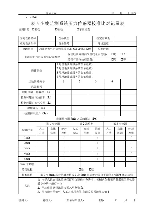
检测时间
第 1 次检测 人工 在线 绝对 方法 监测 差值
第 2 次检测 人工 在线 绝对 方法 监测 差值
第 3 次检测 人工 在线 绝对 方法 监测 差值
1min
/
/
/
2min
/
/
/
3min
/
/
/
4min
/
/
/
5min
/
/
/
5min 平均值
是否达标
是 否
标准限值 备注
第 1 次 5min 压力绝对差值或 3 次 5min 压力绝对差值平均值均≤50Pa 视为达标
1:电子式仪表记录数据保留至仪器最小分辨率;机械式仪表记录数据保留至仪器 最小分辨率最后一位 2:平均值数据记录四舍五入至整数 Pa 3:压力绝对差值=|人工方法压力值-在线监控系统压力值|
检测人:
复核人:
加油站陪检人:
日期:
年月日
- -J342
有限公司
年 月 日颁布
表 5 在线监测系统压力传感器校准比对记录表
检测目的:验收
抽检
年度检查
检测设备名称
设备状态
检定有效期
检测设备型号
设备编号
环境温度
检测依据 加油站大气污染物排放标准 GB 20952-2007 检测时间
加油站油气回收系统设备参数
各埋地油罐的油气管线是否连通: 是
是否有油气处理装置:
是
操作参数
1 号埋地油罐服务的加油枪数: 2 号埋地油罐服务的加油枪数: 3 号埋地油罐服务的加油枪数: 4 号埋地油罐服务的加油枪数:
埋地油罐编号
1
2
3
4
否 否
(完整版)加油站流量计自校记录表(新)
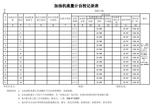
填 报
序 号
加油站名 加油 称 枪号
加油机规 格型号
前次自校时 累计泵码
本次自校累 计泵码
总累计泵码
自校 周期
1
2
3
4
5
9
填报日期:
自校记录 标准量器示值 油枪出 高度 体积 口油温
10
11
12
标准量 器内油
温
13
实际体积
相对误 差(%)
14
15
备注
1
1
1个月
度: 2.54L/mm, ß=0.000033
11
13
1个月
19.850
19.837 -100.00
12
14
1个月
19.850
19.837 -100.00
13
15
1个月
19.850
19.837 -100.00
14
16
1个月
19.850
19.837 -100.00
单位负责人:
制表:
联系电话:
填报说明: 1、以加油机每累计发油30万升为自校周期的,直接填报。 2、以加油机累计工作1个月为周期的,在“自校记录”处注明,在相应的泵码的栏处填报日期。 3、每月5日前上报上月自校情况,联系人:丁涛,029-87453057 4、备注栏应分站注明所使用标准量器信息:器号、检定有效期、标准高度、标准体积、颈分度等。
19.837 19.837 19.837 19.837 19.837 19.837 19.837
-100.00 -100.00 -100.00 -100.00 -100.00 -100.00 -100.00
器号:BJL20 有效期 至:2013年 1月17日, 标准高度: 58.96mm, 标准体积: 20L颈分
汽车燃油压力传感器测试仪

键按下,自动关机功能不被允许,测试仪必须手动关机。
自动关机设置在系统关机后将被保留和存储,开机后设置仍然 有效。
5.11 数字滤波器选择
①、按下左图所示的键 2 秒
②、测试仪进入菜单设置,显示如左图。
或
③、按下左图所示的键,跳过自动关机设置,进入 数字滤波器设置
11
PDF 文件使用 "pdfFactory Pro" 试用版本创建
5.7 过压错误(OFL)显示 提示压力超出测量范围。 当输入测试仪的压力小于规定的测量范围,屏幕还显
示本信息,请联系厂商。
9
PDF 文件使用 "pdfFactory Pro" 试用版本创建
5.8 零点校准 在没有压力情况下,零点可以被手动校准。
注:为了保证正确设置零点值。应确保此操作在无输入压力的情况进行。
SVW 6394 燃油压力传感器测试仪
使用说明书
PDF 文件使用 "pdfFactory Pro" 试用版本创建
目录
1 概述…………………………………………………………………1
1.1 安全注意事项及产品选择性……………………………………………1 1.2 测试仪类型和供货范围…………………………………………………1
4 测量连接……………………………………………………………7 5 测量操作……………………………………………………………8
5.1 开机………………………………………………………………………8 5.2 关机………………………………………………………………………9 5.3 背光开 …………………………………………………………………9 5.4 MiN/MAX 显示……………………………………………………………9 5.5 FS 满量程显示 …………………………………………………………9 5.6 更删除 MiN/MAX 保存值…………………………………………………9 5.7 过压错误(OFL)显示 …………………………………………………9 5.8 零点校准…………………………………………………………………10 5.9 重置零点…………………………………………………………………10 5.10 自动关机功能设置………………………………………………………10 5.11 数字滤波器选择 ………………………………………………………11 5.12 显示系统信息……………………………………………………………12 5.13 与 VAS 测试仪连接 ……………………………………………………13
机动车燃油流量计流量、时间示值误差测量不确定度的评定
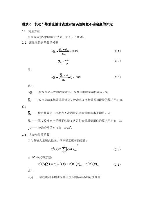
附录C 机动车燃油流量计流量示值误差测量不确定度的评定C .1 测量方法用本规范规定的测量方法如正文6.2.3所述。
C.2 流量示值误差数学模型%10000⨯-=∆iii i Q Q Q Q (C.1)ρii m Q 00=(C.2)即:%100)1(0⨯-⨯=∆ii i m Q Q ρ (C.3)式中:i Q ∆——被校机动车燃油流量计第i 校准点的流量示值误差,%;i Q —— 被校机动车燃油流量计第i 校准点3次测量累积流量的算术平均值,ml ;i Q 0——校准装置第i 校准点3次测量累计流量的算术平均值,ml ; i m 0——第i 校准点电子天平称量3次累积流量质量示值的算术平均值,g ;ρ—— 校准介质的密度值,g/cm 3。
C.3 方差和灵敏系数因为各输入量彼此独立。
依不确定度传播定律:[]212)()(∑==ni i i c x u c y u (C.4)由(C.4)式得方差:ρ)()()()(2232222212x u c x u c x u c Q u m i c ++=∆ (C.5)式中:)(x u ——被校机动车燃油流量计引入的标准不确定度分量;m x u )(——电子天平引入的标准不确定度分量。
ρ)(x u ——密度计引入的标准不确定度分量。
灵敏系数:i ii m Q Q c 01ρ=∂∆∂=(C.6)2002ii ii mQ m Q c ρ-=∂∆∂=(C.7)iii m Q Q c 03=∂∆∂=ρ (C.8) 根据(C.6),(C.7),(C.8)式得标准不确定度:ρρρ)()()()()()()(22022202202x u m Q x u mQ x u m Q u ii m ii ii c +-+=∆ (C.9)C.4标准不确定度分量C.4.1 由被校机动车燃油流量计引入的标准不确定度分量)(x uC.4.1.1 由被校机动车燃油流量计测量重复性引入的标准不确定度分量1)(x u选取15L/h 、50L/h 、100L/h 、150L/h 、200L/h 、250L/h 六个校准点在重复性条件下,对Corrsys-Datron 的CDS-DFL3x-5bar 型机动车燃油流量计各流量分别进行10次等精度测量,介质密度0.8403/g cm ,数据见表C.1,用贝塞尔公式(C.10)计算各校准点的实验标准差:∑=--=ni i i x x n x S 12)(11)( (C .10)实际校准中,以3次测量结果的算术平均值为测量结果,其标准不确定度分量为:3)()(1i x S x u =(C.11)C.4.1.2 由被校机动车燃油流量计显示分辨力引入的标准不确定度分量2)(x u被校机动车燃油流量计累计流量显示分辨力为0.01ml ,服从均匀分布,则:00279.03201.0)(2==x u ml 由重复性引入的标准不确定度分量大于由分辨力引入的标准不确定度分量,因此可不考虑由分辨力引入的标准不确定度分量,则:1)()(x u x u =C.4.2 由标准装置电子天平引入的标准不确定度分量m x u )(C.4.2.1 由标准装置电子天平测量重复性引入的标准不确定度分量1)(m x u选取15L/h 、50L/h 、100L/h 、150L/h 、200L/h 、250L/h 六个校准点在重复性条件下,对Corrsys-Datron 的CDS-DFL3x-5bar 型机动车燃油流量计各流量分别进行10次等精度测量,介质密度0.8403/g cm ,数据见表C.3,用贝塞尔公式(C.10)计算各校准点的实验标准差;实际校准中,以3次测量结果的算术平均值为测量结果,其标准不确定度分量按公式(C.11)计算。
流量校准记录
校准时大气压:(kPa) 校准时温度:(K) 校准日期: 年 月 日
采样器型号
采样器编号
流量计指示流量(L/min)
水压差△h(mm)
校准流量Q
(L/min)
校准计算公式:Q= ( -a) 其中:a:流量计曲线截距,P1、T1:标准气压(kPa)、标况温度(K),
b:流量计曲线斜率,P2、T2:校准时气压(kPa)、校准时温度(K)
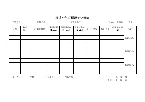
环境空气采样原始记录表
监测项目:采样地点:监测点编号:采样方式: 连续□ 间歇□
日期
样品
编号
采样起止时间
表观流量(L/min)
累积采样时间(min)
流量校准值(L/min)
采样体积(L)
校正系数
标况下体积(L)
备注
仪器名称:
仪器型号:
仪器编号:
采样人 复核 科长审核 质控审核 共 页 第 页
总共 页 第 页
校准人 复核 科长审核 质控审核 共 页 第 页
总共 页 第 页
WFHJ/ZY-C-168(01)
大气采样器流量校准记录表
日期: 校准时大气压:(kPa) 校准时温度(K) 校准时温度下的饱合蒸汽压:(kPa)
采样器型号
采样器编号
流路
表观流量
(L/min)
皂膜mL)
总共 页 第 页
校准流量Q
(L/min)
1
2
3
平均
计算公式:Q= 其中:T1-标况温度(273K) T2-校准时温度(K) t-皂膜通过两刻度间的平均时间(s)
P1-标准大气压(101.325 kPa) P2-校准时大气压(kPa) PV-校准时温度下的饱合蒸汽压(kPa) V-皂膜通过两刻度间的体积(mL)
流 量 显 示 仪 表 检 定 记 录
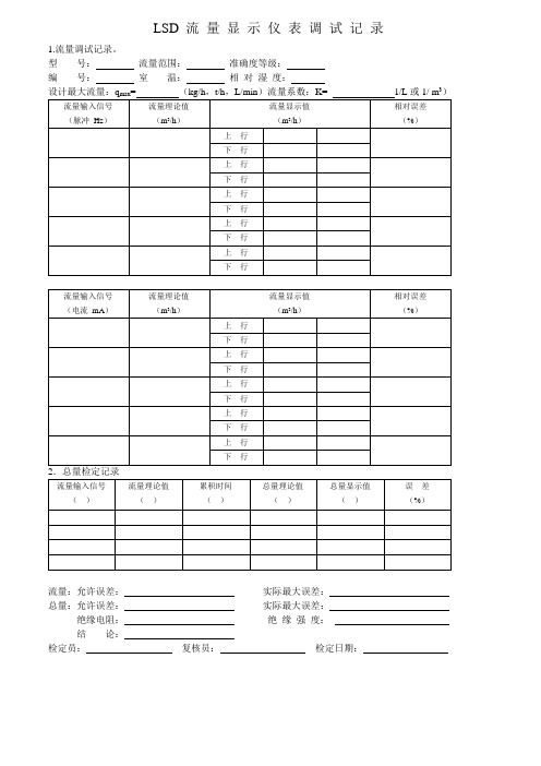
LSD 流量显示仪表调试记录
1.流量调试记录。
型号:流量范围:准确度等级:
编号:室温:相对湿度:
3
流量:允许误差:实际最大误差:
总量:允许误差:实际最大误差:
绝缘电阻:绝缘强度:
结论:
检定员:复核员:检定日期:
流量显示仪表调试检定记录
浙江罗托克自动化仪表有限公司流量显示仪表调试检定记录
注意:检测过程中LSD的仪表系数设为3.6次/升、4-20mA对应最大流量为1600 m/h、压力测试中4-20mA 对应最大压力为1Mpa、输入信号为电流信号时4-20mA对应最大流量为1600 m3/h。
注意:检测过程中LSD的仪表系数设为3.6次/升、4-20mA对应最大流量为1600 m/h、压力测试中4-20mA 对应最大压力为1Mpa、输入信号为电流信号时4-20mA对应最大流量为1600 m3/h。
燃油加油机校准结果不确定度探讨

燃油加油机校准结果不确定度探讨发布时间:2021-10-23T15:31:54.036Z 来源:《基层建设》2021年第20期作者:荆瑞林[导读] 摘要:近年来,随着我国社会主义市场经济的不断发展,越来越多的社会公众开始购买汽车作为日常代步出行的交通工具,也因此增加了对机动车加油等相关话题的讨论度。
新乡县公共检测中心河南新乡 453700摘要:近年来,随着我国社会主义市场经济的不断发展,越来越多的社会公众开始购买汽车作为日常代步出行的交通工具,也因此增加了对机动车加油等相关话题的讨论度。
在此背景下,如何保证作为机动车加燃油工具的燃油加油机测量数值精准成为工作人员研究的重点方向,本文也以此为基础进行深入分析。
关键词:燃油加油机;不确定度;标准金属量器;汽车加油;引言对燃油加油机校准结果的分析探讨一方面能够提高燃油加油机测定的精准度,避免社会公众由于误差等原因出现不必要的损失,另一方面也有助于提高我国强制检测的质量水平,保障我国石油市场以及汽车市场的稳定运转。
在此背景下,本文从燃油加油机的工作结构出发,在深入分析燃油加油机工作的基础上对其校准结果不确定度进行分析探讨。
一、燃油加油机分析(一)燃油加油机工作原理作为一种为机动车添加燃油的一种燃油体积测量系统,燃油加油机在中国各大加油站都有十分重要的地位,是加油站正常运转的关键设备。
在加油站日常工作中,燃油加油机能够有效保障加油站的安全供油以及对燃油的运输和计量,进而为社会公众提供更加安全、稳定的加油方式。
燃油加油机的工作原理是指在抬起油枪后,加油机的开关信号通过电线等系统送入电脑装置,进而启动加油机的电动机,打开防爆电磁阀等内容,并且通过电动机带动加油机的泵将燃油吸入泵内,在经过增压、油气分离等环节后,燃油的流量被记入传感器向电脑进行输出并在电脑装置端显示加油的油量。
通过燃油加油机的工作原理,本文认为把控燃油加油机的校准结果不仅能够有效提高加油过程的燃油流量计算精准度,更能够提高工作人员工作的效率,为社会公众带来更加稳定、安全、精准的机动车加油。
JJG443-2015加油机检定原始记录带计算公式
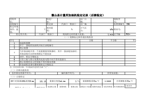
受检单位: 油枪编号 检定环境条件:温度: 检定用介质: 序号 1 2 3 4 5 6 7 8 制造厂家: 检定油品: ℃ 相对湿度: 汽油□ 柴油□ 出厂日期: 汽油□ 柴油□ 出厂编号: % 大气压力: 现场检定时的最大流量: (一)铭牌标记和外观结构检查 合格 规格型号: 标准器编号:396 kPa 铅封号: L/min 证书编号: F03不合格 不适用
20.0 20.0 20.0
100.000 100.000 100.000
0.00 0.00 0.00
0.00
检定结论: 检定员: 复核员: 检定日期: 年 月 日
:396
F03不适用
9 ×10⁻⁴ 重复性
E n/%
0.00
0.00
项目 加油机铭牌 多于一条枪的加油机应标注油枪编号 指示装置 当多条油枪共用一个流量测量变换器时,其中一条油枪加油时, 其他油枪应由控制阀锁定不能加油 封印、检定合格标志 计控主板与指示装置的连接电缆中间不得有接插头 指示装置的显示控制板不得有微处理器 在加油机显著位置粘贴检定合格标志
注:在对应的合格、不合格或不适用栏内画“╳”。
20.0 20.0 20.0
100.000 100.000 100.000
0.00 0.00 0.00
0.00
0.36Qmax≤Q(2)≤0.44Qmax
1 2 3
100.00 100.00 100.00
101.10 101.10 101.10
100.00 100.00 100.00
20.0 20.0 20.0
(二)自锁功能检查 监控微处理器序列号: (三)示值检定 20℃时量器100L刻度H/mm 测量点(L/min) 101.10 测量mm
加油机原始记录
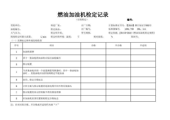
受检单位:
制造厂家:油枪编号:
检定油品:大气压力:
检定用介质:现场检定时最大流量:L/min
相对湿度: %铅封号:(一)名牌标记和外观结构检查序号
1
2
345678
注:在对应的合格、不合格或不适用栏内画“×”编号: 计量标准证书号:【2010】烟计标证字083号 标准器编号: 100L:705 20L:111指示装置
当多条油枪共用一个流量测量变换器时,其中一条油枪加油时 ,其他油枪应由控制阀锁定不能加油
封印、检定合格标志
计控主板与指示装置的连接电缆中间不得有接插头指示装置的显示控制板不得有微处理器
在加油机显著位置粘贴检定合格标志燃油加油机检定记录
(后续检定)
项目加油机铭牌多于一条油枪的加油机应标注油枪编号合格不合格不适用出厂日期:出厂编号:型号规格:检定时的环境: 温度: ℃ 检定依据:JJG443-2015《燃油加油机检定规程》
(二)自锁功能检查:监控微处理器序列号:
(三)示值检定
1100
2100
3100
120
220
3
20检定结论:
检定员:日期:0.36Q L ≤Q (2)≤0.44Q L 复核员:异常加油量:编码器序列号:量期内油温t B /℃实际体积值 V Bt /L 单词测量相对误差E V /%示值误差重复性 E n /%0.90Q L ≤Q (1)≤1.0Q L 测量点 (L/min)测量次
序加油机示值
V J /L
量器刻度H /mm 量器示值V B /L 油枪出口处油温t J /℃。
加油机检定原始记录(带公式)
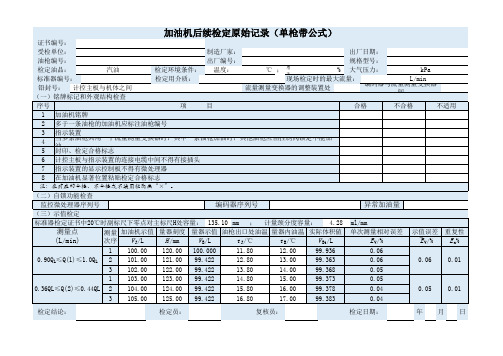
编码器与流量测量变换器 间
序号
项
目
合格
不合格
不适用
1 加油机铭牌
2 多于一条油枪的加油机应标注油枪编号
3 指示装置
4
当多条油枪共用一个流量测量变换器时,其中一条油枪加油时,其他油枪应由控制阀锁定不能加 油
5 封印、检定合格标志
6 计控主板与指示装置的连接电缆中间不得有接插头
7 指示装置的显示控制板不得有微处理器
加油机后续检定原始记录(单枪带公式)
证书编号:
受检单位:
制造厂家:
出厂日期:
油枪编号:
检定油品:
汽油
标准器编号:
铅封号: 计控主板与机体之间
(一)铭牌标记和外观结构检查
检定环境条件: 检定用介质:
出厂编号: 温度:
规格型号:
℃ ; 相 对 现场检定时的最大%流量大:气压力:
kPa L/min
流量测量变换器的调整装置处
次序 V J/L
H /mm
V B/L
t J/℃
t B/℃
V Bt/L
1 100.00 120.00 100.000
11.80
12.00
99.936
单次测量相对误差 E V/% 0.06
示值误差 重复性
`E V/%
E n%
0.90QL≤Q(1)≤1.0QL 2 3
101.00 102.00
121.00 122.00
99.422 99.422
12.80 13.80
13.00 14.00
99.363 99.368
0.06 0.05
0.06 0.01
1 103.00 123.00 99.422
油耗仪操作规程学习资料

油耗仪操作规程油耗仪的操作规程一.连接方式:油耗仪的连接方法一共有三种,这些取决汽车发动机燃油系统的构造及燃油泵的位置。
1.发动机不带回油(直接在油箱里回油)这个的安装最为简单,即只要把流量传感器串接在供油油路上即可(不需要用到热交换器)。
连接时注意流往传感器的方向,在流量传感器有箭头标志。
2.发动机带回油,燃油泵在油箱内部。
这时的连接方法如下图所示。
3.发动机带回油,且油泵是安装在发动机上的,连接安装图如下:3.信号传输连接。
根据不同的构造,选用上面不同的连接方法。
用传感器信号线,一端连接接S8005C(流量传感器)和另一端连接SE8005D(显示器)接口。
4.供电。
需要两根电源线,,分别连入到热交换器,和显示器上的对应接口。
(注,如果采用的是第一种连接方法(发动机不带回油)则不需要使用热交换器HE8005,也就只需一根电源线给SE8005D供电即可。
)二,测试操作1.检查以上连接没问题之后,利用点烟器给设备供电。
(如果采用第一种连接方法直接进入第三步)2.将热交换器上的手柄先调至purge档排气十分钟左右。
3.排气结束后将手柄调制measure档开始测量。
4.打开显示器S8005D,进入测试模式,————点击右上角的main menu———。
点击flow display。
可实时查看瞬时油耗和累计油耗。
二.信号输出。
上图中1用于供电,2,用于连接流量传感器的信号,3用于引入距离信号,6用于连接到电脑上,7用于连接触发开关。
4,5用用于信号输出,4为模拟量输出,K=65mv/(l/h),5为脉冲输出,(100Pulses/ml).可通过BNC线4,5信号输出到其他的采集设备上比如说,VBOX3i采集器。
(5可连接到FIM03, 4可连接到ACD03或自带的四个模拟量通道。
)。
油耗传感器JT606操作手册V1.3

JT606操作手册V1.3深圳久通机电有限公司2012年11月12日1 JT606介绍....................................................................................................................... - 3 -2.外观及规格 ....................................................................................................................... - 3 -2.1 外观.......................................................................................................................................... - 3 -2.2 规格.......................................................................................................................................... - 5 -3 接线定义.......................................................................................................................... - 6 -4 截断和校准 ...................................................................................................................... - 7 -4.1 截断.......................................................................................................................................... - 7 -4.1.1 油箱高度测量.......................................................................................................................................... - 7 -4.1.2 细屑清理................................................................................................................................................ - 10 -4.1.3 底塞固定................................................................................................................................................ - 12 -4.2 油位传感器校准 ......................................................................................................................- 12 -4.2.1按键校准................................................................................................................................................ - 14 -4.2.1.1 按键说明..................................................................................................................................... - 16 -4.2.1.2调满............................................................................................................................................. - 17 -4.2.1.3调零............................................................................................................................................. - 17 -4.2.1.4检验............................................................................................................................................. - 18 -5. 安装及布线 ................................................................................................................... - 18 -5.1 钻孔.........................................................................................................................................- 18 -5.2 安装及固定 .............................................................................................................................- 19 -5.3 布线.........................................................................................................................................- 21 -6. 油位传感器与GP6000的连接 ...................................................................................... - 21 -6.1 油位值和油箱容积的设定 .......................................................................................................- 21 -6.2 客户端软件配置 ......................................................................................................................- 22 -1 JT606介绍JT606系列油位传感器是由久通机电公司独立研发,具有多项创新技术。
机动车燃油流量计校准规范JJF(机械)1046-2020
JJF(机械)1046-2020目录引言 (I)1范围 (1)2引用文件 (1)3概述 (1)4计量特性 (1)5校准条件 (2)5.1环境条件 (2)5.2标准装置 (2)6校准项目和校准方法 (2)6.1校准项目 (2)6.2校准方法 (3)7校准结果的表述 (5)8复校时间间隔 (5)附录A燃油流量传感器连接参考方法 (6)附录B机动车燃油流量计校准原始记录表 (10)附录C机动车燃油流量计流量示值误差测量不确定度的评定 (11)附录D机动车燃油流量计时间示值误差测量不确定度的评定 (16)附录E校准证书或校准报告内容 (19)JJF(机械)1046-2020引言本规范依据JJF1071-2010《国家计量校准规范编写规则》、JJF1001-2011《通用计量术语及定义》、JJF1059.1-2012《测量不确定度评定与表示》编制。
本规范替代JJF(汽车)06-2008《燃油流量计校准规范》,与JJF(汽车)06-2008《燃油流量计校准规范》相比,除编辑性修改外,本规范的主要技术变化如下:——按JJF1002-2010《国家计量检定规程编写规则》规定,将原“2引用文献”改为“2引用文件”。
——修改“概述内容”。
——修改“4.2测量范围”的要求。
——修改“5.1环境条件”的要求。
——增加“6.2.2传感器压力损失检查”的方法。
——重新评定机动车燃油流量计流量示值误差测量不确定度。
——增加“附录D机动车燃油流量计时间示值误差测量不确定度的评定”。
本规范所替代规范的历次版本发布情况为:——JJF(汽车)06-2008《燃油流量计校准规范》。
机动车燃油流量计校准规范1范围本规范适用于新制造、使用中和维修后的机动车燃油流量计的校准(其他类似设备可参考本规范进行校准)。
2引用文件本规范引用了下列文件:JJF1001-2011通用计量术语及定义JJF1059.1-2012测量不确定度评定与表示JJF1071-2010国家计量校准规范编写规则JJF1094-2002测量仪器特性评定与表示JJF(汽车)08-2008燃油流量计校准规范凡是注日期的引用文件,仅注日期的版本适用于本规范;凡是不注日期的引用文件,其最新版本(包括所有的修改单)适用于本规范。
机动车燃油流量计校准规范JJF(机械)1046-2020

JJF(机械)1046-2020目录引言 (I)1范围 (1)2引用文件 (1)3概述 (1)4计量特性 (1)5校准条件 (2)5.1环境条件 (2)5.2标准装置 (2)6校准项目和校准方法 (2)6.1校准项目 (2)6.2校准方法 (3)7校准结果的表述 (5)8复校时间间隔 (5)附录A燃油流量传感器连接参考方法 (6)附录B机动车燃油流量计校准原始记录表 (10)附录C机动车燃油流量计流量示值误差测量不确定度的评定 (11)附录D机动车燃油流量计时间示值误差测量不确定度的评定 (16)附录E校准证书或校准报告内容 (19)JJF(机械)1046-2020引言本规范依据JJF1071-2010《国家计量校准规范编写规则》、JJF1001-2011《通用计量术语及定义》、JJF1059.1-2012《测量不确定度评定与表示》编制。
本规范替代JJF(汽车)06-2008《燃油流量计校准规范》,与JJF(汽车)06-2008《燃油流量计校准规范》相比,除编辑性修改外,本规范的主要技术变化如下:——按JJF1002-2010《国家计量检定规程编写规则》规定,将原“2引用文献”改为“2引用文件”。
——修改“概述内容”。
——修改“4.2测量范围”的要求。
——修改“5.1环境条件”的要求。
——增加“6.2.2传感器压力损失检查”的方法。
——重新评定机动车燃油流量计流量示值误差测量不确定度。
——增加“附录D机动车燃油流量计时间示值误差测量不确定度的评定”。
本规范所替代规范的历次版本发布情况为:——JJF(汽车)06-2008《燃油流量计校准规范》。
机动车燃油流量计校准规范1范围本规范适用于新制造、使用中和维修后的机动车燃油流量计的校准(其他类似设备可参考本规范进行校准)。
2引用文件本规范引用了下列文件:JJF1001-2011通用计量术语及定义JJF1059.1-2012测量不确定度评定与表示JJF1071-2010国家计量校准规范编写规则JJF1094-2002测量仪器特性评定与表示JJF(汽车)08-2008燃油流量计校准规范凡是注日期的引用文件,仅注日期的版本适用于本规范;凡是不注日期的引用文件,其最新版本(包括所有的修改单)适用于本规范。
车辆检测传感器数据表说明书
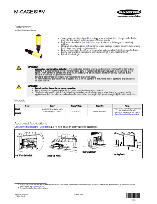
DatasheetVehicle Detection Sensor•3-axis magnetoresistive-based technology; senses 3-dimensional changes to the Earth’s magnetic field caused by the presence of ferrous objects•Easy sensor installation (see Installation on p. 5); above- or below-ground mounting options•Compact, robust one-piece, self-contained sensor package replaces inductive-loop sensing technology; no external controller needed•Designed to minimize the effects of temperature swings and destabilizing magnetic fields •Sensor learns ambient background and stores settings in non-volatile memory •Patented technologiesWARNING:•Appropriate use for vehicle detection —The mechanical opening, braking, and reversing systems of the door will notrespond in sufficient time to prevent moving trucks, cars, or material handling vehicles, even those traveling at low speeds, from coming in contact with the door. In addition, the detection zone of the device may fluctuate due to changes in the local magnetic environment.•Failure to follow these procedures may result in serious injury or death.•All vehicles should approach doors at speeds that allow the operator to ensure the door is operating properly and inan open position.WARNING:•Do not use this device for personnel protection•Using this device for personnel protection could result in serious injury or death.•This device does not include the self-checking redundant circuitry necessary to allow its use in personnel safetyapplications. A device failure or malfunction can cause either an energized (on) or de-energized (off) output condition.ModelsApproved ApplicationsSee Approved Applications - Extended on p. 2 for more details on factory-approved applications.Car Wash Entry/ExitDrive-Up KioskOverhead DoorLoading Docksuffix “W/30” to the model number of any cabled sensor (for example, S18MB W/30). A model with a QD connector requires a2Consult factory for other output options.M-GAGE S18MOriginal Document 114430 Rev. D22 June 2020114430OverviewThe M-GAGE S18M sensors implement a passive sensing technology to detect large ferrous objects. The sensor measures the change in the Earth’s natural magnetic field (the ambient magnetic field) caused by the introduction of a ferromagnetic object.This easy-to-use sensor is extremely robust and is unaffected by dirt and moisture,making it ideal for demanding outdoor environments. Simple programming procedures provide flexibility for a variety of applications (see page 5).Theory of OperationThe sensor uses three mutually perpendicular magnetoresistive transducers. Each transducer detects magnetic field changes along one axis. By incorporating three sensing elements, maximum sensor sensitivity is achieved.A ferrous object will alter the local (ambient) magnetic field surrounding the object. The magnitude of this magnetic field change is dependent both on the object (size, shape,orientation, and composition) and on the ambient magnetic field (strength and orientation).During a simple programming procedure, the S18M measures the ambient magnetic field. When a large ferrous object (for example, a truck, automobile, or rail car) alters that magnetic field, the sensor detects the magnetic field changes (anomalies). When the degree of magnetic field change reaches the sensor’s threshold, the sensor’s discrete outputs switch.Sensor Field of View and RangeThe sensor range depends on three variables:1.The local magnetic environment (including nearby ferrous material)2.The magnetic properties of the object to be sensed3.Sensor settingsThe S18M can detect changes in the ambient magnetic field in all directions. As with other sensors, the range will depend on the target. The strong disturbance of a large ferrous object decreases as the distance from the sensor increases, and the magnitude and shape of the disturbance is dependent on the object’s shape and content.The sensor can be programmed to react to magnetic field disturbances of greater or lesser intensity using two adjustments: background condition and sensitivity level.Once background condition and sensitivity level are set, the sensor is ready to detectthe target object. Both settings are stored in non-volatile memory.Figure 2. Introduction of Large Steel ObjectB. After a large steel target object is introduced, the sensor detects the differential (magnetic strength and orientation) between fields A and B. If the differential is greater than the sensitivity threshold, the sensor’soutputs conduct.Tip: Sensor may be mounted inside a non-ferrous architectural detail for cosmetic or security reasons. It is important that,wherever it is mounted, the sensor is securely attached during configuration and all later use. If the sensor moves after being taught, detection errors may occur and sensor must be re-taught. If a sensor appears to lose its taught settings, it may be a result of having shifted position after setup.Approved Applications - ExtendedThe M-GAGE sensor provides a direct replacement for inductive-loop systems, and needs no external frequency controller box. Unique mounting solutions allow an M-GAGE sensor to be replaced easily without disrupting or re-cutting the pavement. - Tel: + 1 888 373 6767P/N 114430 Rev. DCar Wash Entry/ExitThe Banner M-GAGE vehicle detection sensor will reliably detectvehicles in and around car wash bays. It will reliably detect the presenceor absence of a vehicle to provide collision avoidance at the exit of aconveyorized tunnel, provide an entry or exit-door trigger, or trigger anundercarriage wash.Overhead DoorThe Banner M-GAGE sensor can be used to trigger the opening andclosing of high-traffic internal overhead doors. Mounted in the floor, it willreliably detect forklifts or trucks as they approach the doors. Banner’sapplications engineers are available to help determine proper sensorplacement for specific door-trigger applications.Drive-Up KioskThe Banner M-GAGE sensor reliably detects vehicles at drive-throughsystems or other drive-up kiosks. It will reliably detect a vehicle to triggerpersonnel that a vehicle is present, and to initiate a timing system.Loading DockThe Banner M-GAGE sensor provides multiple advantages for loadingdocks. It will reliably detect the presence of a vehicle as it backs into adock, triggering a light on the interior of the building to notify the dockattendant that a vehicle is in position for loading/unloading. The M-GAGEcan also be used to trigger dock/ramp leveling systems.Sensor ConfigurationFor most applications, configure the M-GAGE sensor remotely, via the DPB2 Portable Programming Box, which provides programming access to an underground or otherwise inaccessible sensor. For optimum performance, the sensor must be secured so that it will not move either during or following configuration.Configuration using the sensor’s built-in push button is useful primarily for demonstration and troubleshooting purposes.P/N 114430 Rev. D - Tel: + 1 888 373 67673Brown Blue Gray White or Black Power ON LEDConfiguration/Output ON LED Push ButtonFigure 3. Sensor FeaturesBrown Blue Gray White or BlackFigure 4. Connecting to the model DPB2 Portable Programming BoxConfiguration via the DPB2 Portable Programming BoxSet Background Condition (No Vehicle Present)Wire the M-GAGE ™ sensor as directed. Remove all vehicles and all other metal objects that are temporarily in the sensing area before setting the background condition.Set Sensitivity LevelLevel 1 = least sensitive, Level 6 = most sensitive.•Double-click the push button to save the setting.Set Push Button Enable/DisableM-GAGE S18M - Tel: + 1 888 373 6767P/N 114430 Rev. DConfiguration via the Sensor Push ButtonFollow the instructions in Configuration via the DPB2 Portable Programming Box on p. 4, with the following exceptions.Set Background Condition (No Vehicle Present):•Press and hold the push button for 2 seconds, until the Output LED turns red.•Release and then click the push button once.Set Sensitivity Level:•Press and hold the push button for 2 seconds, until the Output LED turns red.•Release and then quickly double-click the push button. Increase the sensitivity by increments as described in Configuration via the DPB2Portable Programming Box on p. 4.•When the sensor is set to the desired sensitivity level, double-click the push button to return the sensor to RUN mode.Wiring+10 - 30V dc –+10 - 30V dc –1 = Brown2 = White3 = Blue4 = Black5 = GrayInstallationBelow-Grade InstallationMaterials•M-GAGE S18M Sensor •SMP1 Conduit Plug•2" Schedule 80 rigid PVC conduit (1.5" may be used if there is only one 90° bend); total length and number of elbows depend on installationlayout•2" (or 1.5") rigid PVC end cap (1 per installation)•¾" I.D. flexible, liquid-tight, non-metallic conduit (same length as PVC conduit used for application)•DPB2 Portable Programming BoxFigure 5. Below-grade installationProcedurey out 2" (or 1.5") PVC in the desired configuration. For the best sensor performance, the sensing location (located at the end of theconduit run) should be 6" below the final surface. Provide an access point where the PVC comes above grade (where the sensor and flex conduit can be fed in or pulled out, as required).2.Secure the end cap to the PVC, at the sensing location.3.Measure the overall length of the PVC run, from the sensing location to the control panel.4.Cut a section of ¾" flex conduit to span the total distance from the control panel to the sensing location.5.Thread the sensor into the SMP1 conduit plug. Feed the sensor cable into the flex conduit, until the sensor and plug are snugly seated in theend of the flex conduit.6.Feed the flex conduit by hand, sensor-end first, into the PVC access point until the sensor reaches the PVC end cap.7.Secure the remaining flex conduit from the access point to the control cabinet.8.After the sensor is configured (see following section), wire the sensor into the control device and power supply per the wiring diagram onpage 8.Above-Grade Installation•M-GAGE S18M Sensor •SMP2 Conduit Plug•¾" Schedule 40 PVC electrical conduit; total length and number of elbows depend on installation layout •Electrician’s fishtape •Silicone adhesive•DPB2 Portable Programming BoxP/N 114430 Rev. D - Tel: + 1 888 373 676751.Mount the PVC electrical conduit from the sensing point to the control panel. Plastic conduit should be used for at least the first 6.1 m (20')from the sensing point; metal or flexible conduit may be used the remainder of the distance.2.Thread the S18M sensor into the threads of the SMP2 conduit plug.3.Feed the fishtape into the conduit, from the control panel towards the sensing point.4.Pull the sensor cable back through the conduit, until the sensor almost reaches the end of the plastic conduit. Do NOT pull sensor intoconduit.5.Apply a small amount of silicone adhesive to the outside of the conduit at the sensing point end.6.Press the conduit plug into the end of the conduit.7.After the sensor is configured (see following section), wire the sensor into the control device and power supply per the wiring diagram onpage 8.Typical Target Excess Gain CurvesAfter the sensor has been securely mounted and configured, it is ready to operate. The following two example applications shows typical responses for the M-GAGE ™ sensor.Figure 7 on p. 6 describes mounting the M-GAGE ™ 1 meter (3.3 ft) above the ground to sense an automobile. The graph shows the excess gain for a typical car. Excess gain is a measure of theamount of extra signal detected by the sensor over and above the Level needed to detect the target.This example assumes a Level 5 sensitivity threshold.The table at right compares the change in excess gain if the sensitivity Level changes. If thesensitivity is at Level 6, then the excess gain at a given distance would be 1.3 times larger than for a Level 5 sensitivity. Conversely, if the sensitivity threshold is Level 1, then the excess gain would be one third as big as for Level 5.Excess Gain vs Sensitivity Level(Assumes Level 53)M-GAGEis not a factor .2.5 m (8.0')2.0 m (6.4')1.5 m (4.8')1.0 m (3.2')0.5 m(1.6')Distance from Vehicle SideE x c e s s G a i n (S e n s i t i v i t y L e v e l 5)012345678Figure 7. Application example 1: sensor mounted 1 meter (3.3 ft) above groundFigure 8 on p. 7 illustrates a typical vehicle passing over a sensor mounted underground. Note that excess gain is greatest when the bulk of the vehicle (the rear axle) is positioned directly over the sensor. - Tel: + 1 888 373 6767P/N 114430 Rev. D(0.8')M-GAGEM-GAGENOTE: Sensor orientationis not a factor .1.2 m -1.2 m2.4 m (8')-2.4 m3.7 m (12')4.9 m (16') 6.1 m (20')7.3 m (24')E x c e s s G a i n (S e n s i t i v i t y L e v e l 5)0.6 m (2')-0.6 m (-2') 1.2 m (4')-1.2 m (-4') 1.8 m (6')-1.8 m (-6') 2.4 m (8')-2.4 m (-8') 3.1 m (10') 3.7 m (12') 4.3 m (14') 4.9 m (16') 5.5 m (18') 6.1 m (20') 6.7 m (22')7.3 m (24')0 m 0123456Distance from Vehicle Front BumperFigure 8. Application example 2: sensor mounted 0.25 meters (0.8 ft) below groundSpecificationsSupply Voltage10 to 30V dc (10% max. ripple) at 43 mA, exclusive of loadAbove +50° C (+122° F), supply voltage is 10 to 24V dc (10% max. ripple)Sensing RangeSee Figure 7 on p. 6 and Figure 8 on p. 7Sensing TechnologyPassive 3-axis magnetoresistive transducer Supply Protection CircuitryProtected against reverse polarity and transient voltages Output ConfigurationTwo SPST solid-state outputs conduct when object is sensed; one NPN (current sinking) and one PNP (current sourcing)Output ProtectionProtected against short-circuit conditions AdjustmentsConfiguration of Background Condition and Sensitivity Level may be set using the sensor’s push button or remotely via the portable programming box IndicatorsTwo indicatorsPower Indicator: GreenConfiguration/Output Indicator: Red/Yellow ConstructionThreaded Barrel: Thermoplastic polyester Push Button Housing: ABS/PC Push Button: Santoprene Lightpipes: AcrylicOutput Ratings100 mA maximum (each output)NPN saturation: < 200 mV at 10 mA and < 600 mV at 100 mA NPN OFF-state leakage current: < 200 microampsPNP saturation: < 1.2V at 10 mA and < 1.6V at 100 mA PNP OFF-state leakage current: < 5 microamps Output Response Time 20 milliseconds Delay at Power-Up 0.5 seconds Temperature Effect < 0.5 milligauss / ºCRemote TEACH Input Impedance 12K ohms Operating Conditions–40 °C to +70 °C (–40 °F to +158 °F)100% maximum relative humidity Connections2 m or 9 m shielded 5-conductor (with drain) PVC jacketed attached cable or 5-pin Euro-style quick-disconnect Environmental RatingLeak proof design is rated IEC IP69K; NEMA 6P Vibration and Mechanical ShockAll models meet Mil. Std. 202F requirements method 201A (vibration: 10 to 60Hz max.,double amplitude 0.06 in, maximum acceleration 10G). Also meets IEC 947-5-2: 30G 11 ms duration, half sine wave.CertificationsDimensions(0.24")P/N 114430 Rev. D - Tel: + 1 888 373 67677AccessoriesCordsetsBanner Engineering Corp Limited WarrantyBanner Engineering Corp. warrants its products to be free from defects in material and workmanship for one year following the date of shipment. Banner Engineering Corp. will repair or replace, free of charge, any product of its manufacture which, at the time it is returned to the factory, is found to have been defective during the warranty period. This warranty does not cover damage or liability for misuse, abuse, or the improper application or installation of the Banner product.THIS LIMITED WARRANTY IS EXCLUSIVE AND IN LIEU OF ALL OTHER WARRANTIES WHETHER EXPRESS OR IMPLIED (INCLUDING, WITHOUT LIMITATION, ANY WARRANTY OF MERCHANTABILITY OR FITNESS FOR A PARTICULAR PURPOSE), AND WHETHER ARISING UNDER COURSE OF PERFORMANCE, COURSE OF DEALING OR TRADE USAGE.This Warranty is exclusive and limited to repair or, at the discretion of Banner Engineering Corp., replacement. IN NO EVENT SHALL BANNER ENGINEERING CORP. BE LIABLE TO BUYER OR ANY OTHER PERSON OR ENTITY FOR ANY EXTRA COSTS, EXPENSES, LOSSES, LOSS OF PROFITS, OR ANY INCIDENTAL, CONSEQUENTIAL OR SPECIAL DAMAGES RESULTING FROM ANY PRODUCT DEFECT OR FROM THE USE OR INABILITY TO USE THE PRODUCT, WHETHER ARISING IN CONTRACT OR WARRANTY, STATUTE, TORT, STRICT LIABILITY, NEGLIGENCE, OR OTHERWISE.Banner Engineering Corp. reserves the right to change, modify or improve the design of the product without assuming any obligations or liabilities relating to any product previously manufactured by Banner Engineering Corp. Any misuse, abuse, or improper application or installation of this product or use of the product for personal protection applications when the product is identified as not intended for such purposes will void the product warranty. Any modifications to this product without prior express approval by Banner Engineering Corp will void the product warranties. All specifications published in this document are subject to change; Banner reserves the right to modify product specifications or update documentation at any time. Specifications and product information in English supersede that which is provided in any other language. For the most recent version of any documentation, refer to: .For patent information, see /patents.© Banner Engineering Corp. All rights reserved。
流量计校正报告表表格
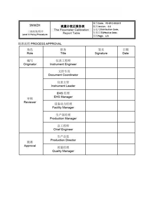
环境湿度
3
WI编号
4
校正种类:□定期校正□不定期校正□新品校正□维修校正□其他
5
校正时使用之标准器
标准仪器编号
6
校正方式
序号
设定值
( )
实际读数
最大误差
( )
上行
下行
7
是否合格:□是□否判定者:
判定基Hale Waihona Puke :a.最大误差<=±1.0%。
工程师:校正者:保存期限:3年
批准流程PROCESS APPROVAL
角色
Role
职务
Title
签名
Signature
日期
Date
编写
Originator
仪表工程师
InstrumentEngineer
审核
Reviewer
文控专员
Document Coordinator
仪表主管
Instrument Leader
EHS经理
EHS Manager
设备动力经理
Facility Manager
生产部经理
Production Manager
总工程师
Chief Engineer
批准
Approval
生产总监
Production Director
质量经理
Quality Manager
文件修订历史REVISION HISTORY
版次
Version
日期
Date
修订原因
Causes for revising
修订页数
Revising Pages
0.0
SNWZH新3级程序。
- 1、下载文档前请自行甄别文档内容的完整性,平台不提供额外的编辑、内容补充、找答案等附加服务。
- 2、"仅部分预览"的文档,不可在线预览部分如存在完整性等问题,可反馈申请退款(可完整预览的文档不适用该条件!)。
- 3、如文档侵犯您的权益,请联系客服反馈,我们会尽快为您处理(人工客服工作时间:9:00-18:30)。
附录A机动车燃油流量计连接参考方法
单个流量传感器连接方法参考图1。
图1 单个流量传感器油路连接图
燃油流量计校准装置电路控制图如图2、图3所示。
图2燃油流量计校准装置(质量法)电路控制图
图3 燃油流量计校准装置(容积法)电路控制图
带回油装置汽油电喷流量传感器连接方法参考图4(以小野MF-2200为例)。
图4 带回油装置汽油电喷流量传感器连接图
校准方法:
1)按照上图连接被校机动车燃油流量计。
调压阀(relief valve)的调压范围为(0~100) kPa。
2) 打开外加泵1(pump 1),确认MF-2200上的压力表P3指示在(80~100)kPa。
3) MF-2200上的泵开关置于ON。
4) 调节调压阀,使MF-2200上的压力表P2指示到100kPa左右。
5) 开关阀V2全开,调节V2使流量显示值约在50 l/h,并确认MF-2200上的压力表P1指示到(10~20)kPa。
在此状态下,燃油开始循环并排出配管内的空气。
6) 当空气完全排出后,调节流量阀V1选取校准流量点,关闭V2,将电子
天平置零并处于开始测量状态,打开V2,在选取校准的流量点采样后关闭V2,记录下电子天平的读数值和DF/FM系列显示仪上的累计流量值,每校准点重复测
量三次。
带回油装置柴油电喷流量传感器连接方法参考图5(以小野MF-3200为例)。
图5 带回油装置柴油电喷流量传感器连接图
校准方法:
1) 按照上图连接被校机动车燃油流量计。
2) 打开MF-3200上的泵开关。
3) 开关阀V2全开,调节流量调节阀V1使流量显示值约在50l/h,并确认MF-3200上的压力表P1指示到(10~20)kPa。
在此状态下,燃油开始循环并排出配管内的空气(此时球阀关闭)。
4) 当空气完全排出后,关闭V1、V2。
5) 调节流量阀V1选取校准流量点,关闭V2,将电子天平置零并处于开始测量的状态,打开V2,在选取校准的流量点采样后关闭V2,记录下电子天平的
读数值和DF/FM系列显示仪上的累计流量值,每校准点重复测量三次,采样时间应保证在20s以上。
附录B 机动车燃油流量计校准原始记录表
机动车燃油流量计校准原始记录表
送检单位:仪器型号:传感器编号:环境温度:仪器编号:传感器编号:校准介质:介质密度:校准员:校准日期:流量系数:核验员:。
