林内燃气灶英文说明书ZTD90F-F
使用说明书-林内
意烫伤。
禁止
如将锅柄置于排气口上,锅柄受热,损
伤锅柄。
烹饪以外不要使用 请勿用于烘干衣服类、引燃蜂窝煤等 可能引起火灾、损伤器具。 请勿将排气扇、冷暖风机的风吹到器 具上,可能引起器具损伤、动作不良。
禁止
不要让儿童触摸 可能发生受伤或烫伤等意外事故。 提示: 不要误使用燃烧器的操作按钮。 使用中,不要操作燃气阀门来熄火, 避免烫伤或意外事故发生。
大锅架 灶具用火力调节杆 灶具用操作按钮 各个按钮上 标明了所对 应的灶眼
左侧点火锁定开关
烤箱门 烤箱拉手 电池盖 电池更换信号灯 盛水盘 盛水盘支架
大锅架 小锅架 排气口罩子 排气口 烹调时排气处
面板
烤箱用火力调节杆 右侧点火锁定开关 烤箱用操作按钮 按钮上表示了 的图标
烤箱烤网
1
各部分的名称及作用
保养工具和洗涤剂
14
除了本使用说明书之外,还有安装
保养要点
14
说明书。由于在器具的移置、替换、
常见的故障识别和处理
16
修理中要用到,因此请与本说明书
电池更换
18
一起妥善保管。
关于安装
18
如果使用说明书遗失,可向售后服
器具安装后长期不使用的处置/规格
19
务中心联系。
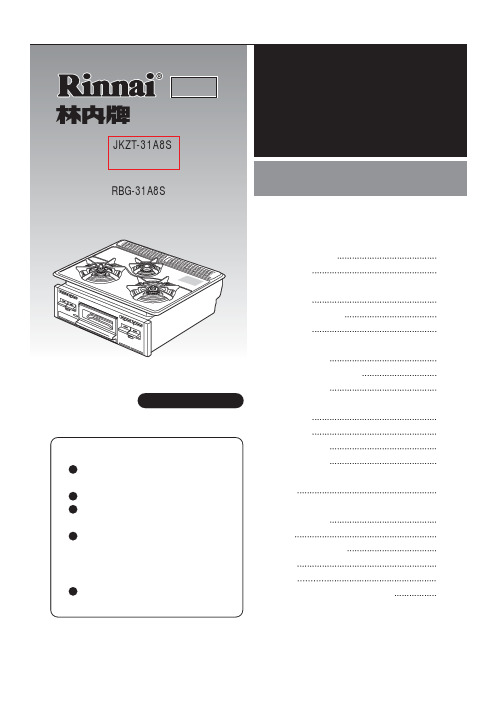
各部分的名称及作用
强火力燃烧器 小火燃烧器 标准燃烧器 (附温度传感器)
家庭用
型 号:JKZT-31A8S 产品编号:RBG-31A8S(有水单面烧烤型)
烤箱灶
使用说明书
成套厨房用(嵌入式)
目录
各部分的名称及作用
1
安全注意事项
3
使用前的准备
干电池的安装
5
厨房标准温度开关说明书

Series TCS
Thermocouple Temperature Switch
Heating and Cooling Control, 16 Amp Rating, Two Alarms
Temperature Switches, Digital
Monitor and control temperature in heating and cooling applications with the Series TCS Thermocouple Switch. The Series TCS offers a wide temperature range, two selectable alarm sets, and an internal buzzer indicating alarm condition or error. The user can define set point, heating/cooling regulation, cycle time, alarm configuration, load status, and ambient probe adjustment. The thermocouple switch features password protection and error/alarm messaging. Temperature and output status is indicated on the bright red LED display. Use the configuration key (sold separately) to quickly program multiple units. The Series TCS includes a fitting clip for panel mounting, gasket, rear terminal cover and instruction manual.
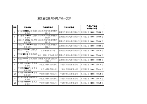
浙江省已备案消毒产品一览表
3
西门子牌ZTD90A-N01型食具消毒柜
江苏博西家用电器销售有限公司
宁波安佳卫厨电器有限公司
浙卫消证字(2003)第020号
4
西门子牌ZTD90A-N02型食具消毒柜
江苏博西家用电器销售有限公司
宁波安佳卫厨电器有限公司
浙卫消证字(2003)第020号
5
林内牌ZTD90L-L型食具消毒柜
40
帅康牌ZTD110K-S1型食具消毒柜
浙江帅康电器股份有限公司
浙江帅康电器股份有限公司
浙卫消证字(2002)第066号
41
帅康牌ZTD90K-02型食具消毒柜
浙江帅康电器股份有限公司
浙江帅康电器股份有限公司
浙卫消证字(2002消毒柜
浙江帅康电器股份有限公司
德意牌ZTD1102型食具消毒柜
浙江德意橱具有限公司
浙江德意橱具有限公司
浙卫消证字(2003)第035号
17
德意牌ZTD1101型食具消毒柜
浙江德意橱具有限公司
浙江德意橱具有限公司
浙卫消证字(2003)第035号
18
迅达牌ZTD95-F6型嵌入式食具消毒柜
嵊州市迅达厨房电器有限公司
嵊州市迅达厨房电器有限公司
浙江省已备案消毒产品一览表
序号
产品名称
产品责任单位
产品生产单位
产品生产单位
卫生许可证号
1
西门子牌ZTD90A-01型食具消毒柜
江苏博西家用电器销售有限公司
宁波安佳卫厨电器有限公司
浙卫消证字(2003)第020号
2
西门子牌ZTD90A-02型食具消毒柜
江苏博西家用电器销售有限公司
ECO-4000 350L 500L 燃气炉产品说明书

INSTALLATIONAND OPERATING INSTRUCTIONSModels: Start with the prefix ECO 4000:350L, 500LECO-4000INTENDED FOR OTHER THAN HOUSEHOLD USERETAIN THIS MANUAL FOR FUTURE REFERENCEUNIT MUST BE KEPT CLEAR OF COMBUSTIBLES AT ALL TIMESFOR YOUR SAFETY: Do not store or use gasoline or other flammable vapors and liquids in the vicinity of this or any other appliance.WARNING: Improper installation, adjustment, alteration, service or maintenance can cause property damage, injury or death. Read the Installation, Operating and Maintenance Instructions thoroughly before installing or servicing this equipment.Improper installation, adjustment, alteration, service or maintenance can cause property damage, injury or death. Read the Installation, Operating and Maintenance Instructions thoroughly before installing or servicing this equipment.This equipment has been engineered to provide you with year-round dependable service when used according to the instructions in this manual and standard commercial kitchen practices.P/N 8898810 5/12Phone: +1 (214) 421-7366 Fax:+1 (214) 565-0976 Toll Free: +1 (800) 527-2100 Website: E-mail:*****************APWWYOTT729 Third Avenue Dallas, TX 75226IMPORTANT FOR FUTURE REFERENCEPlease complete this information and retain this manual for the life of the equipment. ForWarranty Service and/or Parts, this information is required.Model Number Serial Number Date PurchasedTABLE OF CONTENTSSECTION ITEM PAGE SECTION ITEM PAGE1 Owner’s Information2 7 Cleaning 52 Safety Information 2 8 Troubleshooting 63 Safety Signs and Messages 3 9 Preventative Maintenance 64 Specifications 3 10 Wiring Diagrams75 Installation Instructions 4 11 Parts Lists & Exploded Views86 Operation 5 12 Warranty 12WARNING: In Europe, appliance must be connected by an earthing cable to all other unitsin the complete installation and thence to an independent earth connection in compliancewith EN 60335-1 and/or local codes.WARNING:An earthing cable must connect the appliance to all other units in thecomplete installation and from there to an independent earth connection.1) OWNER’S INFORMATIONGeneral Information:1. Always clean equipment thoroughly before first use. (See general cleaning instructions).2. Check rating label for your model designation and electrical rating.3. For best results, use stainless steel counter tops.General Operation Instructions:1. All food-service equipment should be operated by trained personnel.2. Do not allow your customers to come in contact with any surface labeled "CAUTION HOT".3. Never touch quartz or steel heaters.Warranty Information:Reliability Backed By APW Wyott’s Warranty:All APW Wyott Toaster Ovens are backed by a one year parts and labor warranty, including On-SiteService calls within 50 miles of authorized service technicians.Service Information:Service Hotline (800) 733-22032) SAFETY INFORMATIONAPW Wyott equipment is designed, built, and sold for commercial use and should be operated by trained personnel only. Clearly post all CAUTIONS, WARNINGS and OPERATING INSTRUCTIONS near each unit to insure proper operation and to reduce the chance of personal injury and/or equipment damage. This product is used for the cooking, defrosting or re-thermalization of food products only.Always disconnect power before servicing the unit. Surfaces will remain hot after power has been turned off. Allow unit to cool before cleaning or servicing. Never clean the unit by immersing it in water. The unit is not protected against water jets; DO NOT CLEAN THE TOASTER OVEN WITH A WATER JET. Always clean equipment properly before first use.3) Safety Signs and MessagesThe following Safety signs and messages are placed in this manual to provide instructions and identify specific areas where potential hazards exist and special precautions should be taken. Know and understand the meaning of these instructions, signs, and messages. Damage to the equipment, death or serious injury to you or other persons may result if these messages are not followed.This message indicates an imminently hazardous situation which, ifnot avoided, will result in death or serious injury.This message indicates a potentially hazardous situation, which, ifnot avoided, could result in death or serious injury.This message indicates a potentially hazardous situation, which, ifnot avoided, may result in minor or moderate injury. It may also beused to alert against unsafe practices.This message is used when special information, instructions oridentification are required relating to procedures, equipment, tools,capacities and other special data.4) SPECIFICATIONSECO 4000 (OR QST)VOLTS WATTS PHMODELECO 4000 -350L 120 1700 1ECO 4000 -500L 208 2800 1ECO 4000 -500L 240 2800 1Power Cord:Six (6) foot, 3 wire grounded cord. If the supply cord is damaged, the manufacturer, or an authorized service agent, must replace it in order to avoid a hazard and warranty. Please contact the factory by calling the 800 # located on the unit.Shipping Weight:ECO 4000-350L ECO 4000-500L54 Lbs (24.5 kg) 54 Lbs (24.5 kg)5) INSTALLATION INSTRUCTIONSIf the carton appears damaged, or damage is discovered once the carton is opened, stop immediately and contact the freight company to file a damage claim.CAUTION: The ECO TOASTER Oven is shipped assembled except for installation of thecrumb tray assembly. Please remove all supports and packaging materials beforeoperating the unit. Failure to remove all packaging materials may lead to a fire and / ordamage to the appliance.1. Remove all external packaging that is protecting top portion of unit2. Remove unit from shipping container while in the upright position. The unit can be lifted out of the cartonby grasping under the back side and the conveyor of the appliance. Please remove the plastic bag.3. Remove all internal packaging to the unit, if present.4. Visually inspect all external and internal portions of unit for damage. Important: Inspect the Quartzelements located inside the oven tunnel after removal of packing material. To inspect the quartz elements, use a small mirror held under and over each element to detect cracks. Important: The quartz elements are fragile and will break under stress. Do not twist, pull, push, or otherwise subject the quartz elements to stress.5. Wipe down the exterior of the unit using a damp cloth with warm water. Do not use abrasive pads orcleaners as they will damage the stainless steel surface.NOTE: DO NOT USE CLEANERS OF ANY KIND ON THE QUARTZ HEATERS.Note: Ambient Conditions - Make sure that the operating location is in an area where the ambienttemperature is held constant (minimum 70°F). Please avoid areas such as near exhaust fans and airconditioning ducts.Warning! Operating environmentEnsure that operation location is at a reasonable distance from combustible walls and materialsotherwise combustion or discoloration could occur. Do not cover the rear inlets or the side inlets andoutlets. Restricting or covering the air inlets and outlets may cause the unit to overheat and WILLvoid your warranty.Caution! Operating environmentPlace unit on a stable, level counter at a convenient height for use. Turn the adjustable feet so thatunit is level to counter top. The top of the unit is not intended for use a shelf. Materials placed thereare at risk for fire.6. Before plugging unit into wall, make sure that the power switch located on the back of “E” models and onthe Front of the “L” model is in the off position.7. Warning!Ensure no hands, tools or parts or other unintended items are located on the conveyor asinjury will result when unit is turned on.8. Plug unit into grounded electrical outlet with correct voltage, and plug configuration.Warning! Using any receptacle that is not designed to match the attached cord and plug MAY cause personal injury and WILL void your warranty. Please attach the ECO-4000, to an individual branch circuit.6) OPERATION1. The controls that operate the belt conveyor speed and the heaters are located on the front of the unit.2. The On/Off switch is used to turn the unit on or off. Once the unit is turned on the conveyor will automaticallyrun. Warning: Ensure no hands, tools or parts are located on the conveyor as injury will result when unit is turned on.3. Note: Before moving the On / Off switch to the "On" position, please read the following statements:4. A. CAUTION! HOT SURFACES! The exterior metal surfaces of the unit will get hot enough to cause burns.Avoid touching these surfaces to prevent injury.B. WARNING! SEVERE BURN HAZARD QUARTZ HEATERS. The quartz heaters or metal heaterslocated in the top of the unit operate at very high temperatures. DO NOT TOUCH HEATERS AFTER UNIT IS TURNED ON.5. This oven has 2 heating zones, 1 above the conveyor, and one beneath the conveyor.Operation Instructions for 350L and 500L1. Turn the Power Switch on located on the rear of the unit. When the unit is “ON”, the conveyorbelt will move.2. Use the “TOP HEAT” and “BOTTOM HEAT” knobs to adjust to the desired temperature andachieve the toasting pattern. Knobs can be turned to an “OFF” position, turning off the heat in afull run mode. In “E-SAVE” mode, the elements (even if “OFF”) will cycle to keep cavitytemperature up.3. Use the conveyor speed control to get the desired toast quality – “DARK” will run the conveyorslower and “LIGHT” will run the conveyor faster.7) CLEANINGInsure the appliance has been turned off and has had sufficient time for all surfaces to cool down before cleaning. Use only mild soap and water to clean this appliance. Appliance cleaning should be performed daily. NOTE: DO NOT USE ABRASIVE CLEANING SOLUTIONS ON THIS APPLIANCE.Daily Cleaning•NEVER DIRECTLY SPRAY THE TOASTER WITH CLEANING CHEMICALS, SOLUTIONS, OR WATER.ALWAYS APPLY CLEANING SOLUTIONS TO A CLEANING TOWEL OR CLOTH.•Remove the crumb pans and wipe out debris with a damp rag and mild soap solution.•Using a damp rag with mild soap and water, wipe down the exterior surfaces of the appliance.•Using a damp rag with mild soap solution, wipe down all areas of the conveyor. DO NOT ATTEMPT TO CLEAN THE QUARTZ OR METAL HEATERS.•When units are in the stacked configuration, it is still necessary to clean between the units. Using a damp rag with mild soap and water, wipe down the tops and undersides of all units. Ensure there are no foreign objects between the units that could catch fire.8) Using a damp rag with mild soap and water, wipe the surfaces of thestacking spacers on all four corners.9) TROUBLESHOOTINGAlways ask and check the following:Not getting power:1. Is the unit connected to a live power source of the proper voltage?2. Check the rating label. Is the unit connected to the correct power source?3. Check the circuit breaker.4. Is power switch "ON"?5. If the above checks out, and you still have problems, call your local service agent.Conveyor not working:1. Please refer to "Not getting power" section.2. Check belt for obstructions. Belt may be jammed.3. Note: At slower settings the conveyor moves very slow and may appear stalled, which is not the case.4. If the above checks out, and you still have problems, call your local service agent.Food not cooking properly:1. Please refer to "Not getting power" section.2. Is the controller and speed control adjusted to the desired setting? (See Product Key Programmingsection to check button parameters)3. If the above checks out, and you still have problems, call your local service agent.10) PREVENTATIVE MAINTENANCE SCHEDULE•Please follow the cleaning section for the daily preventative maintenance schedule.•DO NOT USE ABRASIVES OR CLEANING SOLUTIONS ON THIS APPLIANCE.•Routinely check before every operation that adequate distance is allowed between fans and anything that would possibly allow foreign debris or substances to be taken in by inlet fan.•Clean fan guards on a daily basis to ensure proper inlet cooling to electrical components and efficient hot air exhaust.•On a daily basis make sure side walls of tunnel oven remain clean to assist in maintaining even cooking around product. Be careful not to bump or hit the quartz or metal heaters when wiping down.•Ensure belt is properly tensioned as to prevent slippage or binding, which causes strain on motor.•DO NOT ATTEMPT TO MAINTENANCE, SERVICE, OR CLEAN THE QUARTZ OR METAL HEATERS.NOTES:11。
林内内嵌式燃气灶使用说明书
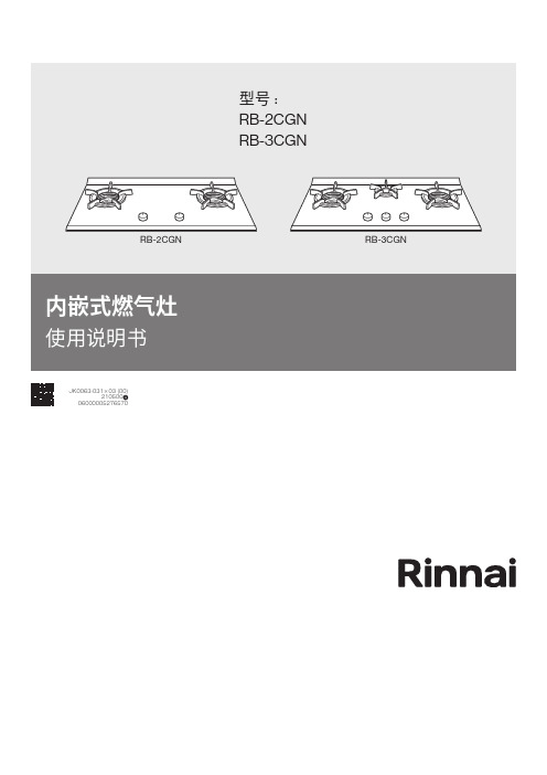
JK0063-031×03 (00)210500060000052765701. 重要警告 (2)2. 安全说明 (3)3. 产品阵容 (5)4. 组件和部件名称 (5)5. 安装 (6)6. 操作说明 (11)7. 维护 (12)8. 故障排除 (12)9. 技术规格 (13)非常感谢您选购林内内嵌式燃气灶。
林内人相信,每次您使用林内产品时,您都能感受到源自产品本身安全性和高品质的便捷舒适之感。
为了实现产品性能的最优化,并保证您的林内内嵌式燃气灶保持最佳的状态,请按照以下的说明小心操作。
1安装并使用林内产品前,请仔细阅读以下所述的说明并按照这些说明进行操作。
由于安装和使用不当造成的任何损失 ,厂家概不负责。
本说明书应与产品一同保存,以便将来参考使用,请尽量将本说明书转交给产品新的所有人。
1.1 总则•产品及其附件在使用过程中会发热。
•用动物油或植物油烹饪食物时无人看管可能发生危险并可能引起火灾。
切勿尝试用水灭火,应先关闭本产品,再用锅盖或灭火毯盖住火焰。
•本产品不得通过外接定时器或独立遥控系统的方式进行操作。
• 请勿在灶台表面存放杂物。
• 请勿使用蒸汽清洁器对产品进行清洁。
1.2 儿童和易受伤害人群警告!窒息、受伤或终生残疾危险•本产品可供年满 8 岁以上的儿童使用,身体机能、感官机能或精神机能下降或经验和知识不足的人员,如果有成人或负责其安全的人员监督,也可以使用产品。
•切勿让儿童玩弄本产品。
•将所有包装材料放在儿童不能接触的地方。
•本产品工作或处于冷却过程时,应让儿童或宠物远离。
•切勿让儿童在无成人看管的情况下独自清洁和维护本产品。
22.1 安装警告!仅限具有相关资质的技术人员安装和维修本产品。
•除去所有包装材料。
• 切勿安装或使用损坏的产品。
•应按照说明保持与其他产品和设备的最小距离。
•移动本产品时,务必佩戴安全手套,小心操作。
• 防止产品底部接触任何蒸汽和湿气。
•防止产品跌落,切勿将产品安装在门附近或窗户下方。
林内燃气热水器各系列产品特点及全参数
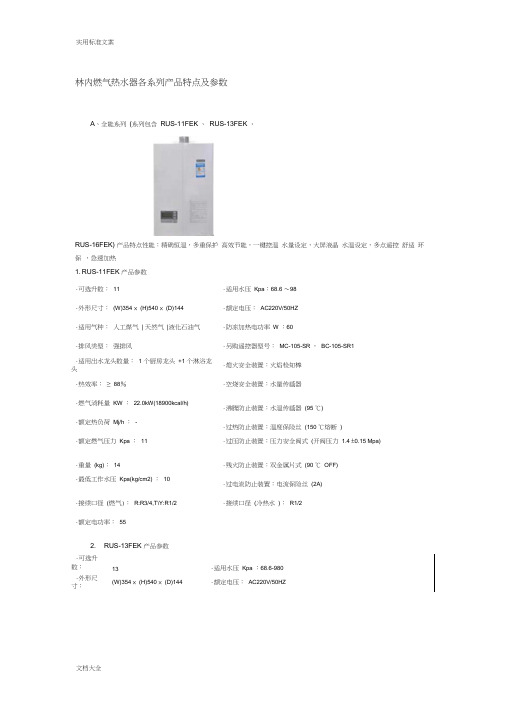
林内燃气热水器各系列产品特点及参数A 、全能系列 (系列包含 RUS-11FEK 、 RUS-13FEK 、RUS-16FEK) 产品特点性能:精确恒温,多重保护 高效节能,一键控温 水量设定,大屏液晶 水温设定,多点遥控 舒适 环保 ,急速加热1. RUS-11FEK 产品参数 ·可选升数:11 ·适用水压 Kpa :68.6 ~98·外形尺寸: (W)354 × (H)540 × (D)144 ·额定电压: AC220V/50HZ·适用气种: 人工煤气 | 天然气 |液化石油气 ·防冻加热电功率 W :60·排风类型: 强排风 ·另购遥控器型号: MC-105-SR , BC-105-SR1·适用出水龙头数量: 1 个厨房龙头 +1 个淋浴龙头 ·熄火安全装置:火焰检知棒·热效率: ≥ 88% ·空烧安全装置:水量传感器·燃气消耗量 KW : 22.0kW(18900kcal/h) ·沸腾防止装置:水温传感器 (95 ℃)·额定热负荷 Mj/h : - ·过热防止装置:温度保险丝 (150 ℃熔断 )·额定燃气压力 Kpa : 11 ·过压防止装置:压力安全阀式 (开阀压力 1.4 ±0.15 Mpa)·重量 (kg): 14 ·残火防止装置:双金属片式 (90 ℃ OFF)·最低工作水压 Kpa(kg/cm2) : 10 ·过电流防止装置:电流保险丝 (2A)·接续口径 (燃气): R:R3/4,T\Y:R1/2 ·接续口径 (冷热水 ): R1/2·额定电功率: 552. RUS-13FEK 产品参数·可选升数: 13 ·适用水压 Kpa :68.6-980·外形尺寸: (W)354 × (H)540 × (D)144 ·额定电压: AC220V/50HZ·适用气种:人工煤气| 天然气|液化石油气·防冻加热电功率W:60·另购遥控器型号:主遥控器:MC-105-SR1 ,浴室用遥控器(另购品):BC- ·排风类型:强排风105-SR1·适用出水龙头数量: 2 个厨房龙头+1 个淋浴·熄火安全装置:火焰检知棒式龙头·热效率:≥88%·空烧安全装置:水量传感器·燃气消耗量KW : 3.9~31.5(3353~27080kc·沸腾防止装置:水温传感器(95 ℃)al/h)·额定热负荷Mj/h :-·过热防止装置:温度保险丝(150 ℃熔断)·额定燃气压力Kpa :0·过压防止装置:压力安全阀式(开阀压力 1.4 ±0.15 Mpa)·重量(kg):14.5·残火防止装置:双金属片式(90 ℃ OFF)·最低工作水压Kpa(kg/cm2) :10(0.1)·过电流防止装置:电流保险丝(2A)·接续口径(燃气):R:R3/4,T\Y:R1/2·接续口径(冷热水):R1/2·额定电功率:60W3. RUS-16FEK 产品参数·可选升数:16·适用水压Kpa :68.6-980·外形尺寸:(W)354 × (H)540 × (D)144·额定电压:AC220V/50HZ·适用气种:人工煤气| 天然气|液化石油气·防冻加热电功率W :60·另购遥控器型号:主遥控器:MC-105-SR1 ,浴室用遥控器(另购品):BC- ·排风类型:强排风105-SR1·适用出水龙头数量:0·熄火安全装置:火焰检知棒·空烧安全装置:水量传感器·热效率:≥88%·燃气消耗量KW : 3.9~31.5(3353~27080kc·沸腾防止装置:水温传感器(95℃ )al/h)·额定热负荷Mj/h :0·过热防止装置:温度保险丝(150℃熔断)·额定燃气压力Kpa :16·过压防止装置:压力安全阀式(开阀压力 1.4 ±0.15 Mpa )·重量(kg) :15kg·残火防止装置:双金属片式(90 ℃ OFF)·最低工作水压Kpa(kg/cm2) :10(0.1)·过电流防止装置:电流保险丝(2A)·接续口径(燃气):R:R3/4·接续口径(冷热水):R1/2·额定电功率:R:65 T:60 Y:70B、双热核冷凝热水器(系列包含RUS-C18FEK 、RUS-C16FEK 、RUS-K2402W(K))产品特点及性能:双重加热,极至节能热效率≥102%科学环保,有效降低废气排放多重安全保护功能,放心使用全智能系统水温、水量精确控制室外吸排,营造室内绿色空间远程多点遥控,舒适、方便①RUS-C18FEK 参数:·可选升数:18·适用水压Kpa :68.6-980·外形尺寸:H660×W366× D175·额定电压:AC220V/50HZ·适用气种:天然气·防冻加热电功率W :130·排风类型:强排风·另购遥控器型号:MC-105-SR ,BC-105-SR1·适用出水龙头数量: 2 个厨房龙头+2 个淋浴龙·熄火安全装置:火焰检知棒头·热效率:≥103%·空烧安全装置:水温传感器·燃气消耗量KW :31·沸腾防止装置:水温传感器·额定热负荷Mj/h :-·过热防止装置:温度保险丝(145 ℃熔断)·额定燃气压力Kpa :2·过压防止装置:压力安全阀式·重量(kg):21.6·残火防止装置:双金属片式(97 ℃ off)·最低工作水压Kpa(kg/cm2) :10·过电流防止装置:电流保险丝(3A)·接续口径(燃气):R1/2·接续口径(冷热水):R1/2·额定电功率:63②RUS-C16FEK 参数:·可选升数:16·适用水压Kpa :68.6-980·外形尺寸:H660×W366× D175·额定电压:AC220V/50HZ·适用气种:天然气·防冻加热电功率W :130·排风类型:强排风·另购遥控器型号:MC-105-SR ,BC-105-SR1·适用出水龙头数量: 1 个厨房龙头+2 个淋浴龙·熄火安全装置:火焰检知棒头·热效率:≥103·空烧安全装置:水温传感器·燃气消耗量KW :27.5·沸腾防止装置:水温传感器·额定热负荷Mj/h :-·过热防止装置:温度保险丝(145 ℃熔断)·额定燃气压力Kpa :2·过压防止装置:压力安全阀式·重量(kg):21.6·残火防止装置:双金属片式(97 ℃ off)·最低工作水压Kpa(kg/cm2) :10·过电流防止装置:电流保险丝(3A)·接续口径(燃气):R1/2·接续口径(冷热水):R1/2·额定电功率:52③ RUS-K2402W(K) 参数:·可选升数:24·适用水压Kpa :68.6-980·外形尺寸:H600×W350× D250·额定电压:AC220V/50HZ·适用气种:天然气·防冻加热电功率W :120·排风类型:室外机·另购遥控器型号:MC-45-A-SR ,BC-33-A-SR·适用出水龙头数量: 2 个厨房龙头+2 个淋浴龙·熄火安全装置:火焰检知棒头·热效率:≥102%·空烧安全装置:水温传感器·燃气消耗量KW :40.8·沸腾防止装置:水温传感器·额定热负荷Mj/h :-·过热防止装置:温度保险丝(145 ℃熔断)·额定燃气压力Kpa :2·过压防止装置:压力安全阀式·重量(kg):30·残火防止装置:双金属片式(97 ℃ off)·最低工作水压Kpa(kg/cm2) :10·过电流防止装置:电流保险丝(3A)·接续口径(燃气):R3/4·接续口径(冷热水):R3/4·额定电功率:52WC、精逸系列(系列包含REU-11/13/16FEA 、RUS-11/13/16FEL 、RUS-11/16FUA/RUS-11/16FUWA RUS-20/24RFJ 、RUS-20/24FEJ 、RUS-11/16FBA 、RUS-11/16RFA) ⅰ:REU-11/13/16FEA 此系列产品已停产。
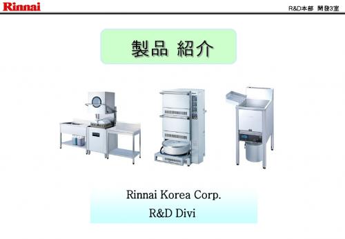
林内商用产品介绍
E(大型) • 型号: RSB-903H/W
仕样
• 尺寸(mm) : 900(W)x750(D)x850(H) /72㎏
• 燃气连接 :1/2”(15A)
• 燃气消费量 : △ LPG : 0.8 Kg/h △ LNG : 9,500 Kcal/h
• 燃气连接:¢9.5(HOSE END) • 内部空间 : 500 * 400(mm) • 燃起消费量 : △ LPG : 1.0 Kg/h △ LNG : 12,300Kcal/h
特征
• 压电式自动点火
• 紫外线BURNER(陶瓷) • 点火手柄在正面使用更加方便 • 可调烤网,支撑台的高度(约 300mm) • 采用了耐久性性良好的不锈钢材料 • 可调火力(强,弱)
• 燃气连接 ::¢9.5(HOSE END)
• 燃气消费量 : △ LPG : 1.0 Kg/h △ LNG : 12,500Kcal/h
特征
• 压电式自动点火
• 点火手柄在正面使用更加方便 • 采用了耐久性性良好的不锈钢材料 • 可调火力(强,弱) • 紫外线BURNER(陶瓷) • 可调烤网,支撑台的高度(约105mm上下移动)
特徵
• 压电式自动点火
• 点火手柄在正面使用更加方便 • 采用了耐久性性良好的不锈钢材料 • 可调火力(强,弱) • 紫外线BURNER(陶瓷) • 可调烤网,支撑台的高度(约105mm上下移动)
R&D本部 開發3室
•产品名 : 燃器烤炉(下火式) • 型号 : RG-640F
仕样
• 尺寸(mm) : 770(W)x630(D)x275(H) /21㎏
•使用电压: AC 220V 50Hz , AC 220V 60Hz (單相) • 燃气连接 :¢9.5(HOSE END) • 额定耗电量: 16W • 燃气消费量 : △ LPG : 1.08 Kg/h △ LNG : 13,000 Kcal/h
锅炉用builtin灶具操作引导书说明书
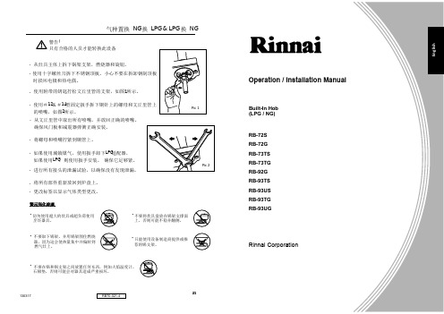
Operation / Installation ManualBuilt-In Hob (LPG / NG)RB-72S RB-72G RB-73TS RB-73TG RB-92G RB-93TS RB-93US RB-93TG RB-93UGRinnai CorporationE n g l i s h252741警告!只有合格的人员才能转换此设备. 从灶具主体上拆下锅架支架,燃烧器和旋钮。
. 使用十字螺丝刀拆下不锈钢顶板。
小心不要在拆卸钢制顶板 时损坏电极和热电偶。
. 使用附带的钥匙拧松文丘里管的支架,如图1所示。
. 使用#12&#14型固定扳手拆下铜针上的螺母和文丘里管上 的喷嘴,如图2所示。
. 从文丘里管中取出所有喷嘴,并放回正确的喷嘴。
确保风门板和减震器弹簧正确安装。
. 将螺母和喷嘴拧紧到铜管上。
. 如果使用城镇煤气,使用扳手卸下LPG 适配器, 如果使用LPG ,则使用扳手安装。
确保它足够紧。
. 进行所有接头的泄漏试验,以确保没有发现泄漏。
. 将所有部件重新放回到炉盘上。
. 更改标签以显示气体类型更改。
Pic 2Pic 1气种置换NG 换LPG & LPG 换NGRB70-021-4130317• 切勿使用超大的炊具或超负荷使用 烹饪器具。
• 不要取下锅架,并用锅架围住燃烧 器,因为这会使热量集中并偏转到 燃气灶上。
• 不要在锅和锅支架之间放置任何东西,例如火焰温度计, 石棉垫,否则可能会对器具造成严重损坏。
• 不要将炊具盘放在锅架支撑面 上,否则可能不稳并翻侧。
• 只能使用设备制造商提供或推 荐的锅支架。
警示强化玻璃ContentGuide to Appliances RB-72S / RB-72G / RB-73TS / RB-73TG / RB-92G / RB-93TS Guide to Appliances RB-93TG / RB-93US / RB-93UGGuide to the AppliancesSpecificationSafety InstructionsUsing for the first timeInstallation GuideOperationSuitable PansCleaning and CareTrouble Shooting GuideRinnai Customer Care CentersConversion from NG to LPG & LPG to NGCaution For the Tempered Glass 123468913151619202121Rinnai Customer Care CentersChina |中国Guangzhou Rinnai Gas & ElectricRoom 2805, No.31 Jianghe Building,Tianshou Road, Guangzhou, China广州林内燃具电器有限公司中国广州天河区天寿路31号江河大厦2805室Tel 电话: (86) 20 3821 7976Email 邮箱:*******************.cnURL 网址: IndonesiaCustomer Care of PT. Rinnai IndonesiaJl. Raya Pejuangan No.21,Komp. Ruko Sastra Graha No.11 -13Jakarta 11530Tel:(62************(Customercare)*************(SMS Center)E mail :**************************URL : www.rinnai.co.idMacau |澳門Rinnai Appliance Service CenterEdificio Industrial, 3andar F.A da Zona Macau林內爐具服務中心澳門青洲跨境工業大廈3樓F座Phone電話 :+853 2852-7799Fax 傳真 : +853 2827-0572URL 网址: /moPhilippinesMitsui Industia Corporation10 Buenaventura St., Cor MacArthurHighway, Dalandan Valenzuela City,PhilippinesTel : (63) 2 292 9177 / 292 9179Fax : (63) 2 292 8187SingaporeRinnai Holdings (Pacific) Pte Ltd 61 Ubi Road 1#02-20 & 21Oxley BizhubSin gap ore 408727Tel : (65) 6748 9478 Fax : (65) 6745 9240Email:********************:www.rinnai.sgThailand | ประเทศไทยRinnai (Thailand) Co., Ltd. / Lucky Flame Co., Ltd.61/1 Soi Kingkaew 9, Kingkaew Rd.Racha Thewa, Bangphli, Samutprakarn 10540,Thailandเลขที่ 61/1 ซอยก่่งแกว9 ถนนก่่งแกประเทศไทย10540Tel : (66) 2 3124330 -40Email:*********************.thURL : www.luckyflame.co.thVietnam | Việt NamRong Viet Commerce Company Limited120 3/2 Street, Ward 12, District 10,Ho Chi Minh City, VietnamCông Ty TNHH Th ngươM i ạRôồn g Vi t ệ120 Đngườ3/2, Ph ngườ12, Qu nậ10,TP. H ôồChí Minh, Vi t ệNamTel : (84) 8 3862 3409 Fax : (84) 8 5404 1964Email:************************URL : www. 40MalaysiaRinnai (M) Sdn BhdD2-3-G & D2-3-1, BlockD2, Pusat PerdaganganDana 1, Jalan PJU 1A/46, 47301 Petaling Jaya,Selangor Darul Ehsan, Malaysia.Tel: (60) 3 7832 0037 / 7832 0038 / 7832 0039Fax: (60) 3 7832 0036 Toll Free : 1800-88-3180Email:***********************.myURL: .myGuide to the AppliancesRB-72SRB-73TS1SmallBurnerLeft Control Right ControlBig BurnerBig BurnerBig Burner Big BurnerBig BurnerRB-72GLeft Control Right ControlExtra Small BurnerLeft Control Right ControlRear RightControlLeft Control Right ControlRear RightControlBig Burner Extra Small BurnerRB-73TGSmallBurnerRB-92GBig Burner Big BurnerLeft Control Right ControlLeft Control Right ControlRear RightControlBig Burner Small BurnerRB-93TSMediumBurner常见问题与解决方法问题可能导致的原因解决方法无点火(DC)自动点火功能不工作燃烧器火焰不均匀。
2021年9月的燃气灶合作公司产品文档说明书
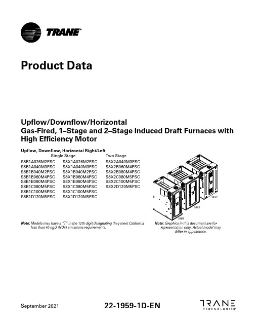
September 202122-1959-1D -E NUpflow/Downflow/HorizontalGas-Fired,1–Stage and 2–Stage Induced Draft Furnaces with High Efficiency MotorU p f l o w ,D o w n f l o w ,H o r i z o n t a l R i g h t /L e f tSingle Stage Two StageS8B1A026M2PSCS8B1A040M3PSC S8B1B040M2PSC S8B1B060M4PSC S8B1B080M4PSC S8B1C080M5PSC S8B1C100M5PSC S8B1D120M5PSCS8X1A026M2PSC S8X1A040M3PSC S8X1B040M2PSC S8X1B060M4PSC S8X1B080M4PSC S8X1C080M5PSC S8X1C100M5PSC S8X1D120M5PSCS8X2A040M3PSC S8X2B060M4PSC S8X2B080M4PSC S8X2C080M5PSC S8X2C100M5PSC S8X2D120M5PSCN o t e :Models may have a “T”in the 12th digit designating they meet Californialess than 40ng/J (NOx)emissions requirements.N o t e :Graphics in this document are forrepresentation only.Actual model maydiffer in appearance.Product DataTable of ContentsGeneral Features (3)Features and Benefits (4)Accessories (5)Product Specifications (6)Airflow Tables (12)CFM Versus Temperature Rise (16)Wiring Diagrams (17)Electrical Connections (20)Field Wiring (20)Outline Drawing (21)General FeaturesN A T U R A L G A S M O D E L SCentral Heating furnace designs are certified by Intertek for both natural and L.P.gas.Limitsetting and rating data were established and approved under standard rating conditions usingAmerican National Standards Institute standards.S A F E O P E R A T I O NThe Integrated System Control is a solid state device which continuously monitors for presenceof flame when the system is in the heating mode of operation.Dual solenoid combination gasvalve and regulator provide additional safety.Q U I C K H E A T I N GDurable,cycle tested,heavy gauge t u b u l a r a l u m i n i z e d s t e e l h e a t e x c h a n g e r quickly transfersheat to provide warm conditioned air to the structure.L o w e n e r g y p o w e r v e n t b l o w e r,toincrease efficiency and provide a discharge of gas fumes to the outside.B U R N E R SMultiport,Inshot burners will give years of quiet and efficient service.All models can beconverted to L.P.g a s with LP conversion kit.I N T E G R A T E D S Y S T E M C O N T R O LExclusively designed operational program provides total control of furnace limit sensors,blowers,gas valve,flame control and includes self diagnostics for ease of service.E N E R G Y EF F I C I E N T O P E R A T I O NAir-Tite™cabinet design is certified to<1%air leakage per ASHRAE193“Method of Test forDetermining the Airtightness of HVAC Equipment.”A I R D E L I V E R YThe9speed constant torque blower motor has sufficient airflow for most heating and coolingrequirements and will switch from heating to cooling speeds on demand from room thermostat.S T Y L I N GH e a v y g a u g e s t e e l a n d"w r a p-a r o u n d"c a b i n e t c o n s t r u c t i o n is used in the cabinet with baked-on enamel finish for strength and beauty.Every orientation has at least two venting options.There are no knockouts on cabinet.F E A T U R E S A N DG E N E R A L O P E R A T I O NThe S-Series furnace utilizes a Silicon Nitride Hot Surface Ignition system,which eliminates thewaste of a constant burning pilot.The integrated system control lights the main burners upon ademand for heat from the room plete front service access.a.Low energy power venterb.Vent proving pressure switches.Features and Benefits80%A F U E o n S8*1a n d S8X2F U R N A C E M O D E L SLowers utility billsE L E C T R I C A L L Y EF F I C I E N TEfficient airflow design reduces electrical energy use34I N C H T A L LLighter,easier to move and fit into tight spaces like short basements or tight closetsWorks great with larger,high-efficiency coilsNo knockouts4–W A Y M U L T I-P O I S ES8*1–8SKU’s—Upflow/Downflow/Horizontal Left/Horizontal RightS8X2–6SKU’s—Upflow/Downflow/Horizontal Left/Horizontal RightAdded application flexibility and reduction in specification errorsA I R F L O WAt least400CFM/ton at0.5in.H20external static pressureR E G U L A T O R YAll models are air tight;1%or less air leakage as per ASHRAE193Open vestibule design provides a full34”high open vestibule for ease of installation and serviceD I ME N S I O N SWidths are industry standard:14.5”,17.5”,21”and24.5”Depth remains approximately28”Cabinet is compatible with industry standard coils,as well as,other accessoriesI N T E G R A T E D F U R N A C E C O N T R O LSetup/Status/Diagnostics/Digital DisplayNo dip switchesLast six errors storedDry contact EAC and HUM connectionsAll Molex connections;no spade terminalsLow voltage labeled above and belowRain shield over IFC keeps condensate off the controlT U B U L A R A L U M I N I Z E D S T E E L H E A T E X C H A N G E RV O R T I C A I I B L O W E R,D E S I G N E D E X C L U S I V E L Y F O R T H E S-S E R I E S F U R N A C EImproved airflow efficiencyDurable,easy to clean,housingSingle piece belly band/motor arm assemblyBlower deck has full-length rails for easy removal and replacement,regardless of poiseF O U R–W A Y M U L T I-P O I S E(U P F L O W,D O W N F L O W,H O R I Z O N T A L L E F T A N D R IGH T)Easier to specifyShipped ready to install(no conversion kits required)Every model has at least two venting optionsAccessoriesTable1.Accessories(a)Airflow greater than1600CFM requires dual returnsProduct SpecificationsP r o d u c t S p e c i f i c a t i o n s(a)Central Furnace heating designs are certified to ANSI Z21.47-latest edition.(b)For U.S.applications,above input ratings(BTUH)are up to2,000feet,derate4%per1,000feet for elevations above2,000feet above sea level.(c)Based on ernment standard tests(d)9Speed constant torque ECM Blower Motor.(e)Refer to the Installer's Guide.(f)The above wiring specifications are in accordance with National Electric Code,however,installations must comply with local codes.P r o d u c t S p e c i f i c a t i o n s(a)Central Furnace heating designs are certified to ANSI Z21.47-latest edition.(b)For U.S.applications,above input ratings(BTUH)are up to2,000feet,derate4%per1,000feet for elevations above2,000feet above sea level.(c)Based on ernment standard tests(d)9Speed constant torque ECM Blower Motor.(e)Refer to the Installer's Guide.(f)The above wiring specifications are in accordance with National Electric Code,however,installations must comply with local codes.P r o d u c t S p e c i f i c a t i o n s(a)Central Furnace heating designs are certified to ANSI Z21.47-latest edition.(b)For U.S.applications,above input ratings(BTUH)are up to2,000feet,derate4%per1,000feet for elevations above2,000feet above sea level.(c)Based on ernment standard tests(d)9Speed constant torque ECM Blower Motor.(e)Refer to the Installer's Guide.(f)The above wiring specifications are in accordance with National Electric Code,however,installations must comply with local codes.P r o d u c t S p e c i f i c a t i o n s(a)Central Furnace heating designs are certified to ANSI Z21.47-latest edition.(b)For U.S.applications,above input ratings(BTUH)are up to2,000feet,derate4%per1,000feet for elevations above2,000feet above sea level.(c)Based on ernment standard tests(d)9Speed constant torque ECM Blower Motor.(e)Refer to the Installer's Guide.(f)The above wiring specifications are in accordance with National Electric Code,however,installations must comply with local codes.P r o d u c t S p e c i f i c a t i o n s(a)Central Furnace heating designs are certified to ANSI Z21.47-latest edition.(b)For U.S.applications,above input ratings(BTUH)are up to2,000feet,derate4%per1,000feet for elevations above2,000feet above sea level.(c)Based on ernment standard tests(d)9Speed constant torque ECM Blower Motor.(e)Refer to the Installer's Guide.(f)The above wiring specifications are in accordance with National Electric Code,however,installations must comply with local codes.Airflow TablesA i r f l o w T a b l e sA i r f l o w T a b l e sA i r f l o w T a b l e sCFM Versus Temperature RiseS8B1/S8X1Furnaces have one stage heatingS8X2Furnaces have two stage heating.First Stage is Low heating and Second Stage is High heating. Table2.S8B1/S8X1Table3.S8X2—Low HeatTable4.S8X2—High HeatWiring DiagramsD346340P01 REV HW i r i n g D i a g r a m sD345844P01 REV FW i r i n g D i a g r a m sElectrical ConnectionsField WiringOutline DrawingTable5.14.5”Wid th Cabin e tT a b l e 6.17.5”W i d t h C a b i n etO u t l i n e D r a w i n gTable7.21.”Wid th Cabin etO u t l i n e D r a w i n gT a b l e 8.24.5”W i d t h C a b i n etO u t l i n e D r a w i n gN o t e sN o t e sN o t e sTrane-by Trane Technologies(NYSE:TT),a global innovator-creates comfortable,energy efficient indoor environments for commercial and residential applications.For more information,please visit or .Trane has a policy of continuous data improvement and it reserves the right to change design and specifications without notice.We are committed to using environmentally conscious print practices.22-1959-1D-EN29Sep2021。
林内燃气灶使用说明书

規格Specifications*禁止使用錫紙碟Never use aluminum tray.the Chinese version shall prevail.注意:Cautions*產品規格及設計如有變更,恕不另行通知。
Specifications are subject to change without prior notice.*中英文版本如有出入,一概以中文版本為準。
If there is any inconsistency or ambiguity between the English version and the Chinese version,型號 LJ-108LJ-1088氣體 額定熱負荷 (kW)4.94.94.9內徑8.8毫米軟喉咀氣體壓力 2900Pa2900Pa點火方式壓電點火Piezoelectric ignitionModel Gas typeRated heat input左爐頭 Left 右爐頭 Right燃氣入口接駁Gas inlet connectionGas pressure Gas ignition system產品尺寸 闊 x 深 x 高 (毫米)Product dimensions W x D x H (mm)Inner diameter 8.8mm flexible tubing gas hose 香港石油氣 HK LPG香港石油氣 HK LPG680 x 410 x 115280 x 410 x 115Thank you for purchasing our product.Before using the product make sure thatyou have followed the safety instructions.Please keep this manual for future reference. There will be improvements on our products. Information is subject to change without prior notice.increase LJ-108 / LJ-1088LIGHTING GAS STOVES TRADING LTD.Flat C&D, 13/F, Fou Wah Industrial Building,10-16 Pun Shan St, Tsuen Wan, Hong KongUser’s Manual(香港石油氣 HK LPG)內容Content氣體接駁需知Gas connection and warning ................................... P.1Parts identification .................................................... P.2各部名稱安裝前須知使用方法清潔及保養常見故障及處理方法Before installation ..................................................... P.3Operating instructions .............................................. P.4-5Cleaning and maintenance ....................................... P.6-7Trouble shooting ...................................................... P.8-9Specifications ............................................................P.10TroubleCauseSolutionBurners cannot be ignitedoffNo flameSmell of gasYellow flameUnstable flame*Warning: If the cooking range cannot be ignited by the above suggested solutions,do not attempt to ignite by other means. Please contact our repair center for repair.規格The main gas supply is turned The ignition knob is notpressed properly or adequatelyGas valve is leakingThe burner cap is not placed properlyNot enough gas in the gascylinder The gas meter control valve and / or the stoves shut-off valve has been turned off Burner cap is blocked by aluminium foilGas pipe had been damaged or not connected well Grease and dirt is accumulated on the burner cap Open gas meter cock and / or Turn it back to the turn off mode. Then, press and turn it anti-clockwise slowly. Since the burner is ignited, keep pressing it for few secondsReplace the burner cap properlyReplace a new gas cylinderContact gas supply company or Wash the burner cap with warm water and detergent. Mop it dayand place it properly appliance isolating cock completelyRemove aluminium foil the registered gas intallers for checkingTurn on the main gas supplyThey should stop the gas flow immediately by turning off the emergency control valvesupstream of the gas meters or the consumers can disconnect the regulators of the LPG cylinders to cut gas supply.Extinguish all naked flames and open all windows and doors wide to disperse the gas.注意!根據香港氣體安全條例,任何氣體裝置工程,包括爐具和接駁喉管的安裝,必須由註冊氣體裝置技工執行,而該技工已於相關的氣體工程類別註冊及受聘於註冊氣體工程承辦商。
GB 家用燃气灶具说明书
ICS 97.040.20Q 82中华人民共和国国家标准GB 16410-201X代替GB 16410-2007家用燃气灶具Domestic gas cooking appliances(征求意见稿)V7-3201X-XX-XX 发布201X-XX-XX 实施目次前言 (4)1范围 (6)2规范性引用文件 (6)3术语和定义 (7)4 产品分类 (9)4.1 灶具的类型 (9)4.2 灶具的型号编制方法 (9)5 要求 (9)5.1 基本设计参数 (9)5.2 性能 (10)5.2.1 气密性 (10)5.2.2 热负荷 (10)5.2.3 燃烧工况 (10)5.2.4 温升 (11)5.2.5 储气罐压力上升最大值 (11)5.2.6 耐热冲击 (11)5.2.7 耐重力冲击 (11)5.2.8 安全装置 (12)5.2.9 电点火装置 (12)5.2.10 使用性能 (12)5.2.11 电气性能 (13)5.2.12 耐用性能 (14)5.2.13 耐振动性能 (14)5.2.14 耐跌落性能 (14)5.2.15 包装承压性能 (14)5.2.16 集成灶吸排油烟装置 (14)5.3 结构 (15)5.3.1 一般结构 (15)5.3.2 灶结构 (16)5.3.3 烘烤器结构 (16)5.3.4 烤箱结构 (17)5.3.5 饭锅结构 (17)5.3.6 烤箱灶结构 (17)5.3.7 集成灶结构 (17)5.3.8 使用交流电源灶具结构的特殊要求 (18)5.3.9 零部件结构 (22)5.3.10 结构尺寸 (24)5.4 材料 (24)5.4.1 材料的一般要求 (24)5.4.2 密封材料 (24)5.4.3 保温材料 (24)5.4.4 导电材料 (24)5.4.5 燃气导管及点火燃烧器导管 (24)5.4.6 旋塞阀 (24)5.4.7 喷嘴 (24)5.4.8 喷嘴座 (24)5.4.9空气调节器(风门) (25)5.4.10燃烧器 (25)5.4.11锅支架 (25)5.4.12盛液盘 (25)5.4.13烤箱内壁、烤盘、烤架及烘烤器辐射板 (25)5.4.14灶脚 (25)5.4.15饭锅内锅 (25)5.4.16包装材料与包装废弃物 (25)5.4.17熄火保护装置火焰检测器 (25)5.4.18集成灶 (25)5.5 外观 (25)6 试验方法 (25)6.1 试验室条件 (25)6.2 试验用燃气 (26)6.3试验用主要仪器仪表 (26)6.4试验设备 (27)6.5灶具试验状态 (27)6.6气密性试验 (27)6.7热负荷试验 (28)6.8燃烧工况试验 (29)6.9温升试验 (32)6.10耐热冲击试验 (34)6.11耐重力冲击试验 (34)6.12安全装置试验 (34)6.13电点火装置试验 (35)6.14使用性能试验 (35)6.15电气性能试验 (38)6.16耐用性能试验 (41)6.17振动试验 (42)6.18跌落试验 (42)6.19结构试验 (42)6.20零部件耐热性能试验 (43)6.21材料试验 (43)7 检验规则 (44)7.1 出厂检验 (44)7.2 型式检验 (44)7.3 单台检验判定原则 (45)8 标志、包装、运输、贮存 (45)8.1 标志 (45)8.2包装 (46)8.3运输 (46)8.4贮存 (46)附录A(资料性附录)家用燃气灶具燃烧烟气中氮氧化物含量[NOx(α=1)]分级规定 (58)附录B(资料性附录)嵌入式灶嵌装开孔尺寸 (59)附录C(规范性附录)集成灶油脂分离度的试验方法 (60)前言本标准为条文强制性标准,标准中的 5.2.1,5.2.2 a、c,5.2.6 d,5.2.7 c,5.2.8.1 b,5.2.8.3,5.2.11.2,5.2.11.3,5.3.1.4,5.3.1.5,5.3.1.10 d、f,5.3.1.12,5.3.1.14,5.3.1.15,5.3.2.6,5.3.7.13, 5.3.8,5.3.9.5a,5.4.1.3,5.4.2.2, 5.4.2.3,5.4.10.1,8.1.1,8.1.2,8.1.3,8.2.3d、e、i、m及表2、表3、表5、表6、表7中的黑体字部分为强制性条文,其余为推荐性条文。
林内

附带燃气专 后上进风设 用管,专用 不要在燃烧 计,无须打开 整机一年保 锅架一个, 的状态下搬 橱柜门或做百 修 开孔样板一 动燃气灶 叶门补充氧气 块 附带燃气专 后上进风设 用管,专用 不要在燃烧 计,无须打开 整机一年保 锅架一个, 的状态下搬 橱柜门或做百 修 开孔样板一 动燃气灶 叶门补充氧气 块 附带燃气专 后上进风设 用管,专用 不要在燃烧 计,无须打开 整机一年保 锅架一个, 的状态下搬 橱柜门或做百 修 开孔样板一 动燃气灶 叶门补充氧气 块 附带燃气专 后上进风设 用管,专用 不要在燃烧 计,无须打开 整机一年保 锅架一个, 的状态下搬 橱柜门或做百 修 开孔样板一 动燃气灶 叶门补充氧气 块
快焰火炉头 设计,火力 集中加热更 快速 快焰火炉头 设计,火力 集中加热更 快速
内外圈火无级 调节,随心所 欲控制火力, 方便烹饪 内外圈火无级 调节,随心所 欲控制火力, 方便烹饪
内外圈火无级 内藏式火 调节,随心所 焰,小火也 欲控制火力, 不易吹灭 方便烹饪 快焰火炉头 设计,火力 集中加热更 快速 内外圈火无级 调节,随心所 欲控制火力, 方便烹饪
RANGE AND STOVE RINNAI R-2CN (Y) 7609
RANGE AND STOVE RINNAI RB-2FTTC(S)(R) 7619
炉头火焰采用 内藏式火 连续分布设 焰,小火也 计,烧菜时能 不易吹灭 均匀加热 炉头火焰采用 内藏式火 连续分布设 焰,小火也 计,烧菜时能 不易吹灭 均匀加热 炉头火焰采用 内藏式火 连续分布设 焰,小火也 计,烧菜时能 不易吹灭 均匀加热 快焰火炉头 设计,火力 集中加热更 快速 内外圈火无级 调节,随心所 欲控制火力, 方便烹饪
210W
750*490*3 不锈钢面板 218W 80mm RANGE AND STOVE RINNAI CXW-220-ESD 7606 904*525*(6 25不锈钢面板 220W 1025)mm RANGE AND STOVE RINNAI R-2CN (R) 7607
林内JZR-3WAX JZR-2WAX家用嵌入式燃气灶说明书
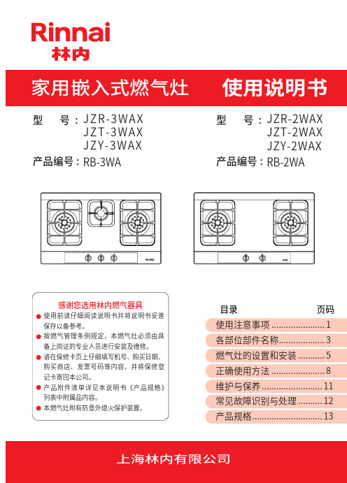
RB-3WA产品编号:型号:RB-2WA产品编号:型号:目录 页码使用注意事项.......................1各部位部件名称.. (3)燃气灶的设置和安装............5正确使用方法.. (8)维护与保养..........................11常见故障识别与处理.. (12)产品规格 (13)上海林内有限公司JZR-3WAXJZT-3WAX JZY-3WAXJZR-2WAXJZT-2WAXJZY-2WAX灶具在使用期间会发热,注意避免接触发热单元。
金属物体如刀、叉、勺和盖不应放在灶台上,因为它们可能变热。
除烹饪外,本燃气灶不得做为他用(如:干燥衣物、煤球助燃等)。
严防小孩擅动燃气灶,操作错误易引起烫伤或火灾。
以防引起异常燃烧或一氧化碳中毒。
禁止禁止禁止燃气灶使用过程中,请打开排气扇,使燃烧废气顺利排至室外,以保持室内空气畅通。
防止通风不良造成一氧化碳中毒。
使用过程中,经常确认火焰是否正常燃烧,使用完毕,请将燃气灶关闭,外出或就寝前一定要关闭燃气阀门。
异常情况(异常燃烧、异常声音、地震、火灾)发生时,请立即停止使用,关闭燃气阀。
发生燃气泄漏时,请立即关闭燃气总阀,敞开门窗保持通风。
这时切忌点火、使用电器开关,火苗、电火花易引起燃气爆炸。
点火时偶遇放手后旋钮未弹起、脉冲音持续,请将燃气灶旋钮至关闭位置。
重新点火若故障仍持续,请通知售后服务维修。
国家对家用燃具有以下安全使用年限规定:燃具从售出当日起,燃气灶具的判废年限应为 8 年。
禁止通风注意必须执行告用户环境影响书:尊敬的用户,图中所示各零部件均在包装箱中,请在装配前按上图逐个 认识各部件。
为保护我们的环境,请按照环保规则处理包装废弃物。
纸质材料请再次循环利用或交给纸品回收站,泡沫聚苯乙烯和塑料薄膜请交给专门废品回收站。
用后的废旧干电池,请按环保要求弃于专用的废物箱。
置于架子上或有落下物的场所,以及塑料请按图示尺寸或包装箱内开孔指示板在料理台上开孔。
杰诺斯 G900 液化气烧烤炉说明书

DESPIECE TECNICOGAMA 900Modelos:BG9-05BG9-10Marzo 2009 MarchRevisado Mayo 2014 May Revised1T055470000PARRILLA INOXIDABLE G9001T055458000PARRILLA DE FUNDICION G9002H015408000SOPORTE PARRILLA G900212044203SOPORTE PARRILLA G900 MEK Q162040000TUERCA EXAGONAL M6Q261040000ARANDELA MUELLE A63H125419000ASA BARBACOA 900 4T065460000EMPUÑADURA5H015407000REJILLA INOX G900 H012616000LATERAL REJILLA G900Q419005000REMACHE 4x8 ALMG3 / ALUMINIO 12010138REMACHE 4x7,5 INOX 6H015406000CAJA INTERIOR G900N100322000COJINETE AUTOLUBRICADO S/NºH012825000POSTERIOR INTERIOR G900 S/NºH012609000ANTERIOR INTERIOR BG900 Q419005000REMACHE 4x8 ALMG3 / ALUMINIO Q221343000REMACHE EXAGONAL M6Q151336000TORNILLO SOPORTE GUIAS7R062810000PANEL LATERAL DERECHO G-900Q221342000REMACHE EXAGONAL M5Q419005000REMACHE 4x8 ALMG3 / ALUMINIO Q162030000TUERCA EXAGONAL M58X162680000ESCUADRA INT. ANTE. MESA 1/2M 8X162690000ESCUADRA INT. ANTE. MESA 1/2M 8U022605000ESCUADRA INT. ANTER. MESA 1M 8U022632000ESCUADRA INT. ANTER. MESA 1M Q012032000TORNILLO EXAGONAL M5x15 A3049R045416000ANTERIOR MESA 1/2M 9S105402000ANTERIOR MESA 1MQ152004000TORN. APLASTADO M5x13 A304 INTRODUCIDO 13.01.14612612 ELIMINADO 01.09.09BENCH FRONT INT BRACKET 1M _1_1BENCH FRONT INT. BRACKET 1/2M 1_1_ELIMINADO 01.09.09INTRODUCIDO 01.09.09FRONT BENCH 1/2M 1_1_BENCH FRONT INT. BRACKET 1/2M 1_1_2__291HEXAGONAL RIVET M5999HEXAGONAL FLAT SCREW M5x13 A 2222012612B G 9-10 P I20_12102 _10B G 9-05 P I1B G 9-10 P FB G 9-05 P FNOTAS1I T E MCODIGO TEXTODENOMINACION RIVET 4X7,5 INOX HEXAGONAL RIVET M6RIVET 4X8 ALMG3 / ALUMINIUM STAINLESS STEEL GRILLE G900REAR INTERIOR G900 CAST IRON GRILLE G900SELF LUBRICATED BEARING 6INOX GRILLE G900 1GRILLE SUPPORTG900 MEK 1HEXAGONAL NUT M62GRILLE SIDE G900 26FRONT BENCH 1M RIGHT SIDE PANEL G-900111ELIMINADO 13.01.14 126INTERIOR BOX G900BENCH FRONT INT BRACKET 1M _1_INTRODUCIDO 01.09.0912211211_1_12FRONT INTERIOR BG900 12121HANDLE 2422ELIMINADO 02.04.124212424INTRODUCIDO 02.04.1242SPRING WASHER A62424424BARBECUE HANDLE 900 22434RIVET 4X8 ALMG3 / ALUMINIUM 173417GUIDE SUPPORT BOLT 88RIVET 4X8 ALMG3 / ALUMINIUM 33883HEXAGONAL NUT M5111316HEXAGONAL BOLT M5x15 A304666ELIMINADO 02.04.12GRILLE SUPPORT G900 1212Pág. 2.Q302022000ARANDELA 16x6x1,2 A30410H012823000PORTAMANDOS BG9-0510H022808000PORTAMANDOS BG9-10 U022836000ESCUDO FAGORQ152004000TORNILLO APLASTADO M5x13 11H012821000ASA BANDEJA IZQUIER. DERECHA Q419005000REMACHE 4x8 ALMG3 / ALUMINIO 12H012612000CAJON RECOGEGRASAS G900 S/NºH012615000REFUERZO CAJON G900 13H012611000BASE BG9-05 COMPLETA 13H022607000BASE BG9-10 COMPLETA 14Z200107000PATA REGULABLEQ221345000REMACHE EXAGONAL M1015H012805000ESCUADRA AMARRE PATA Q162030000TUERCA EXAGONAL M5Q242030000ARANDELA ABANICO A5 A304Q221345000REMACHE EXAGONAL M1016R062811000PANEL LATERA IZQUIERDO G-900Q221342000REMACHE EXAGONAL M5Q419005000REMACHE 4x8 ALMG3 / ALUMINIO Q162030000TUERCA EXAGONAL M5Q242030000ARANDELA ABANICO A5 A30417H012824000PANEL POSTERIOR 1/2M 17H022809000PANEL POSTERIOR 1MQ419005000REMACHE 4x8 ALMG3 / ALUMINIO X010503000CIERRE MUELLEQ419005000REMACHE 4X8 ALMG3 / ALUMINIO 18R205438000SOPORTE EMBELLECEDOR 1/2M 18R205439000SOPORTE EMBELLECEDOR 1M Q419005000REMACHE 4X8 ALMG3 / ALUMINIO 19R205425000EMBELLECEDOR ESMALTE ENAMEL TRIM 1212RIVET 4X8 ALMG3 / ALUMINIUM 2424TRIM SUPPORT 1M_1_11/2M TRIM SUPPORT 1_1_RIVET 4X8 ALMG3 / ALUMINIUM 4444LOCK SPRING2222RIVET 4X8 ALMG3 / ALUMINIUM 4444REAR PANEL 1M_1_1REAR PANEL 1/2M 1_1_FAN WASHER A5 A3041111HEXAGONAL NUT M51111RIVET 4X8 ALMG3 / ALUMINIUM 3333HEXAGONAL RIVET M59999LEFT SIDE PANEL G-9001111HEXAGONAL RIVET M102222FAN WASHER A5 A3044444HEXAGONAL NUT M54444LEG FASTENING BRACKET 2222HEXAGONAL RIVET M104444ADJUSTABLE LEG4444BASE BG9-10 COMPLETE _1_1BASE BG9-05 COMPLETE 1_1_DRAWER REINFORCEMENT G900 1212GREASE COLLECTION DRAWER G91212RIVET 4X8 ALMG3 / ALUMINIUM2424LEFT TRAY HANDLE RIGHT 1212FLAT HEAD SCREW M5X134444FAGOR EMBLEM1111CONTROL HOLDER BG9-10_1_1CONTROL HOLDER BG9-051_1_NOTASWASHER 16x6x1.2 A3042222I T E MCODIGO DENOMINACION TEXTOB G 9-05 P IB G 9-10 P IB G 9-05 P FB G 9-10 P FPág. 2.1T055703000QUEMADOR BARBACOA Q162030000TUERCA EXAGONAL M5Q302022000ARANDELA 16x6x1,2 A3042H122814000TUBO DE ENCENDIDO COMPLETO 212045111TUBO ENCENDIDO + ESCU. PILOTO 3H212819000DISTANCIADOR4H212821000EMBELLECEDOR TUBO ENCEND.Q221324000TUERCA 3/4 GASQ221023000CLIP SUJECIÓN RÁPIDA Ø55U222130000TERMOPAR L=6006U322118000PILOTO COMPLETO 100.062U442137000INYECTOR Ø 0,40 G-N 7X022131000BUJIAR613030000CABLE BUJIA8H015026000TUBO PILOTO BARBACOA 9U333003000CABLE MASA ENCENDEDOR Q563004000LENGÜETA COMPONENTES Q151301000PHILIPS 8x5/810S113034000PIEZOELECTRICO1012043897PIEZOELECTRICO COMPLETO S/Nº12043907ANILLO ADAPTADOR 11U022117000MANDO MONTADO Ø812U022119000GRIFO 18700 BY-PASS 1,3013U912104000BRIDA AMARRE GRIFO 1/2"Q122032000TORNILLO ALLEN M.5x1514U915014000PORTATOBERAS HORNO Q306055000ARANDELA16X10,3X1Q223019000TUERCA 3/8 GAS LATÓN15H015030000CONDUCCION A QUEMADOR COM.Q153002000TORNILLO TAPON NUT 3/8 GAS BRASS 12WASHER 16X10.3X11222INJECTOR Ø 0.40 G-N OVEN NOZZLE HOLDER 1212SPACER12SPARK PLUG CABLEWASHER 16x6x1.2 A30412PHILIPS 8X5/812COMPONENTS TONGUE MOUNTED CONTROL Ø81212THERMOCOUPLE L=6001221PILOT ON + SQUARE TUBE 12INTRODUCIDO 07.05.121BARBECUE PILOT PIPE RAPID CONNECT CLIP Ø524COMPLETE PILOT LIGHT 100,0621SPARK PLUG12BARBECUE BURNER 121212IGNITION PIPE TRIM NUT 3/4 GASCOMP. BURNER PIPE 12CAP BOLT 12TEXTODENOMINACION NOTASB G 9-05B G 9-10I T E MCODIGO HEXAGONAL NUT M512TAP 18700 BY-PASS 1.3012TAP FASTENING FLANGE 1/2"12ALLEN HEAD SCREW M.5x1512COMPLETE IGNITION PIPE 12ELIMINADO 07.05.12PIEZOELECTRIC12ELIMINADO 02.05.12COMPLETE PIEZOELECTRIC 12INTRODUCIDO 02.05.12ADAPTER RING11INTRODUCIDO 02.05.12ELIMINADO 02.05.12LIGHTER EARTH CABLE 12Pág. 5.16R302400000TOBERA Ø 1,65 B-P 16U054400000TOBERA Ø 2,5 G-N 17U325707000REGULADOR DE AIREQ012031000TORNILLO EXAGONAL M5x10 A30418H015027000DISTRIBUIDOR COMPLETO BG9-05 18H015024000DISTRIBUIDOR COMPLETO BG9-10Q221342000REMACHE EXAGONAL M519U635008000TUERCA CIEGA 3/4Q306051000ARANDELA TAPON Ø 23,5x3NOZZLE Ø 1.65 B-P 12HEXAGONAL BOLT M5x10 A30412NOZZLE Ø 2.5 G-N 12AIR REGULATOR12CAP WASHER Ø 23.5x322HEXAGONAL RIVET M512BLIND NUT 3/412COMPLETE DISTRIBUTOR BG9-01_NOTASB G 9-05I T E MCODIGO TEXTODENOMINACION B G 9-10COMPLETE DISTRIBUTOR BG9-1_1Pág. 6.H016502000FOLLETO DE INSTRUCCIONES H016518000FOLLETO DE INSTRUCCIONES BG T056502000CARBON VOLCANICO (BOLSA)ELIMINADO 14.05.09INSTRUCTION LEAFLET 11VOLCANIC ROCK CHARCOAL 12INTRODUCIDO 14.05.09NOTASINSTRUCTION LEAFLET BG 11B G 9-10MOD.BARBACOA I T E MCODIGO TEXTODENOMINACION ZONAPLANO VARIOS B G 9-05Pág. 7.BUTANO - PROPANO 16R302400000TOBERA Ø 1,65S/NºU136501000INDICADOR BUTANO-PROPANOGAS NATURAL 16U054400000TOBERA Ø 2,56U442137000INYECTOR Ø 0,40S/NºU134402000INDICADOR GAS NATURAL GAS VILLA169424500000TOBERA Ø 5,35S/NºU134310000INDICADOR GAS VILLA B G 9-05B G 9-10I T E MCODIGO TEXTODENOMINACION NOTASNOZZLE Ø 1.6512INDICATOR BUTANE-PROPANE11NOZZLE Ø 2.512INJECTOR Ø 0.4012INDICATOR GAS NATURAL11NOZZLE Ø 5.3512TOWN GAS NATURAL GAS BUTANE - PROPANE INDICATOR TOWN GAS11Pág. 8.16U112403000TOBERA Ø 2,65H016515000FOLLETO DE INSTRUCCION. BG-A INSTRUCTION LEAFLET BG-A 11NOZZLE Ø 2.6512NOTASB G 9-10I T E MCODIGO TEXTO DENOMINACION B G 9-05Pág. 9.5U222130000TERMOPAR L=6006U322118000PILOTO COMPLETO 100.062U442137000INYECTOR Ø 0,40 G-N 7X022131000BUJIAR613030000CABLE BUJIA8H015026000TUBO PILOTO BARBACOA1012043897PIEZOELECTRICO COMPLETO S/Nº12043907ANILLO ADAPTADOR12U022119000GRIFO 18700 BY-PASS 1,30C-2176TAP 18700 BY-PASS 1.3012C-2176ADAPTER RING11COMPLETE PIEZOELECTRIC 12C-2176C-2176C-2176BARBECUE PILOT PIPE12C-2176SPARK PLUG12C-2176INJECTOR Ø 0.40 G-N 12C-2176C-2176COMPLETE PILOT LIGHT 100,06212THERMOCOUPLE L=60012SPARK PLUG CABLE 12NOTASI T E MCODIGO DENOMINACION TEXTOB G 9-05B G 9-10MOD.BARBACOA ZONAREPUESTOS RECOMENDADOS RECOMMENDED SPARE PART PLANO Pág. 10.。
燃气灶使用说明书

燃气灶仅可作为一种烹饪电器进行特定使用。不可用在其他方式(如加热房间) 警告 玻璃炉面破损的情况 ● 迅速关闭所有的烹调区,切断电器供电。 ● 不要碰触电器表面 ● 不要使用电器 ● 报专业的售后部门进行维修
1
1. 炒锅炉头 2. 快速炉头 3. 小火炉头
5000W 3800W 1750W
5. 炉架 6. 炒锅炉头控制旋钮
有害部分。 - 特别注意,儿童可能会玩耍废置电器。 - 不要使用潮湿的手和脚碰触电器。 - 不要赤脚踏地使用电器。 - 制造商将不承担任何不恰当、错误和不明原理的使用所造成损坏的责任。 - 使用中,或使用后的一段时间, 灶面的一些部分会十分热,避免碰触它们。 - 使用完毕后,请确认旋钮停在关闭的位置,并关上了燃气阀门。 - 如果燃气喷嘴不能正常使用,请联系服务部门。
不可用在其他方式如加热房间警告玻璃炉面破损的情况报专业的售后部门进行维修gws38110edcn炒锅炉头5000w快速炉头3800w小火炉头1750w小火炉头控制旋钮警告电器可以被8岁以上儿童和缺乏生理感知或精神能力的或缺乏经验和知识者使用但需有具备操作能力并知悉使用安全说明理解所涉及的危险的人监管
2
使用
1)燃气灶 灶的表面,每个旋钮上都有绢印花纹。每个旋钮对应相关灶头。打开总管道或燃气瓶的阀门后,即可进行燃气灶 的点火使用。
- 点火 向下按压并按逆时针方向旋转所需灶头的旋钮,直到最大位置(大火苗 图1),燃气灶头点燃,持续按压约10秒 钟松开手后炉火应保持燃烧状态。
- 灭火保护装置 燃气灶设置有灭火安全保护装置,当热量感应器感应不到热量时燃气阀自动关闭。所以,开始点火时应将旋钮持 续按压几秒钟。
- 没有通电的情况下,灶也能用火柴点燃。 - 在燃气灶使用中不要离开,并持续关注,确保儿童保持安全
林内智家家用供热水燃气快速热水器说明书
注意
即使您改变了热水器的设定温度,循环管道中保温的热水温度是不会改变的,请注意小心烫伤,尤其是当您降 低热水器的设定温度时。因为管道中保温的热水比设定温度更烫。
4 打开热水龙头,已设定好温度的热水即会流出
● 热水使用中,本体操作部的燃烧指示灯会亮起来。 ● 热水使用完毕,关闭热水龙头后,燃烧器火焰和指示灯会自动熄灭。 ● 再度使用时,只需打开热水龙头即有设定好的热水流出来。
排水栓 燃气接口
■ 水泵扬程表
水泵扬程
放水螺栓
水过滤网 (放水螺栓)
进水接头
电源线
水泵扬程(kPa)
循环水量(L/min)
1
初次使用时,请参照下列程序
1 请将进水阀完全打开。
4 请将燃气阀门完全打开。
初次使用
2 打开热水龙头,确认有水流出后
再将热水龙头关闭。
3 插入电源插头,或将空气开关拨到
“开”的位置。
热水使用中水温调节方向
● 往“ ”按时 , 会变化至 60 ℃。每按一次变化一段。如果按住“ ”2 秒以上时,会连续变化至 48 ℃。48 ℃以上时每按 一次变化一段,往“ ”按时,会变化至 35 ℃。但是,当热水使用中从 48 ℃以下往“ ”按时,只能变化至 48 ℃,必 须关闭热水龙头以后才能往上调温;而往“ ”按时,可以从 60 ℃变化至 35 ℃。这是为了防止淋浴时发生烫伤事故而设 计的安全锁定功能。
感谢您选用林内燃气器具
● 使用前请仔细阅读说明书并将说明书妥善保存以备参考。 ● 请在保修页上仔细填写型号、购买日期、购买商店、发票号码等内容,并将保修登记卡寄回本公司。 ● 按燃气管理条例规定,本热水器必须由具备上岗证的专业人员进行安装。安装后,安装人员应向用户介绍热水器使
洁迪炉直吸自然气炉型号:4415 HO GSR2 产品说明书
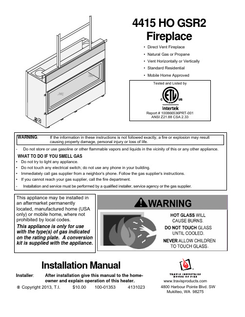
4415 HO GSR2 Fireplace• Direct Vent Fireplace • Natural Gas or Propane • Vent Horizontally or Vertically • Standard Residential • Mobile Home ApprovedTested and Listed byReport # 100866536PRT-001ANSI Z21.88 CSA 2.33WARNING : If the information in these instructions is not followed exactly, a fire or explosion may result causing property damage, personal injury or loss of life.-Do not store or use gasoline or other flammable vapors and liquids in the vicinity of this or any other appliance.WHAT TO DO IF YOU SMELL GAS • Do not try to light any appliance.• Do not touch any electrical switch; do not use any phone in your building.• Immediately call gas supplier from a neighbor's phone. Follow the gas supplier's instructions. • If you cannot reach your gas supplier, call the fire department. - Installation and service must be performed by a qualified installer, service agency or the gas supplier.This appliance may be installed in an aftermarket permanentlylocated, manufactured home (USA only) or mobile home, where not prohibited by local codes.This appliance is only for use with the type(s) of gas indicated on the rating plate. A conversion kit is supplied with the appliance.Installation ManualInstaller :After installation give this manual to the home-owner and explain operation of this heater.© Copyright 2013, T.I. $10.00 100-01353 41310234800 Harbour Pointe Blvd. SWMukilteo, WA 982756Installation Options•Residential or Mobile Home •Straight or Corner Placement •Raised or Floor Placement • Internal or External Chase • Bedroom ApprovedHeating SpecificationsNatural Gas Propane Approximate Heating Capacity (in square feet)* Up to 2,100 Up to 2,100 Maximum BTU Input Per Hour 42,000 42,000 * Heating capacity will vary with floor plan, insulation, and outside temperature.Dimensions9 Fireplace Placement Requirements•Fireplace must be installed on a level surface capable of supporting the fireplace and vent•Fireplace must be placed directly on wood or non-combustible surface (not on linoleum or carpet)•Fireplace should be located out of traffic and away from furniture and draperies.•Fireplace must be placed so the gaps below and above the glass frame do not become blocked.•Fireplace may be placed in a bedroom. Please be aware of the large amount of heat this appliance produces when determining a location.Clearances(a) Clearance to Side of Fireplace 5/8” (16mm). Do not place insulation in this space.NOTE: Drywall or other combustible may contact the side of the fireplace in front of the framing. Thematerial must not protrude in front of the fireplace and may be a maximum ½” (13mm) thick.(b) Clearance to Back of Fireplace 1/8” (4mm). Do not place insulation in this space.(c) When installed, walls in front of the fireplace must be a minimum 3” (77mm) to the side of the fireplace.Raised Fireplaces•The fireplace (and hearth, if desired) may be placed on a platform designed to support the fireplace and vent.•The base of the fireplace must be a minimum 60” below the room ceiling.The firebox opening is approximately 10.375” (264mm) above the base of the fireplace. For atypical raised fireplace of 36” (915mm), place the fireplace on a platform 25.625” (651mm) tall.Minimum Framing Dimensions(a) Minimum Enclosure Height 60”Corner InstallationsA typical 45° installation uses the framing dimensions shown in the illustration below (NOTE: all clearances still apply).13 Gas Line RequirementsMASSACHUSETTS INSTALLATIONS - WARNING:THIS PRODUCT MUST BE INSTALLED BY A LICENSED PLUMBER OR GAS FITTER WHEN INSTALLED WITHIN THE COMMONWEALTH OF MASSACHUSETTS.OTHER MASSACHUSETTS CODE REQUIREMENTS:•Flexible connector must not be longer than 36 inches.•Shutoff valve must be a “T” handle gas cock.•Only direct vent sealed combustion products are approved for bedrooms or bathrooms.•Fireplace dampers must be removed or welded in the open position prior to the installation of a fireplace insert or gas log.• A carbon monoxide (CO) detector is required in the same room as the appliance.•The gas line must be installed in accordance with all local codes, if any; if not, follow ANSI 223.1 and NFPA 54(88), in Canada follow CSA B149.1 and the requirements listed below.•The fireplace and gas control valve must be disconnected from the gas supply piping during any pressure testing of that system at test pressures in excess of 1/2 psig (3.5 kPA). For pressures under 1/2 psig (3.5kPA), isolate the gas supply piping by closing the manual shutoff valve.•Leak test all gas line joints and the gas control valve prior to and after starting the fireplace.•This unit has been listed using the included internal gas shutoff valve.Fuel•This fireplace is designed either for natural gas or for propane (but not for both).Gas Line Connection•Installation must be performed by a qualified installer, service agency or the gas supplier (In Massachusetts a licensed plumber/gasfitter).Gas Inlet Pressure Maximum Input PressureMinimum Input PressureNatural Gas 7" W.C. (1.74 kPA) 5.5” W.C. (1.37 kPA)Propane 13" W.C. (3.23 kPA)11” W.C. (2.74 kPA)•If the pressure is not sufficient, make sure the piping used is large enough, the supply regulator is adequately adjusted, and the total gas load for the residence does not exceed the amount supplied.•The supply regulator (the regulator that attaches directly to the residence inlet or to the propane tank) should supply gas at the input pressure listed above. Contact the local gas supplier if the regulator is at an improper pressure.Directions for Connecting a Gas Pressure Test GaugeThe gas control valve (shown to the left) has two accessible ports for testingline pressure and output pressure. Loosen the brass screw on either test portand place a 5/16” i.d. rubber or plastic tubing over the tapered test port.Connect the tubing to the test gauge.Vent Requirements•The gas appliance and vent system must be vented directly to the outside of the building, and never be attached to a chimney serving a separate solid fuel or gas-burning appliance. Each direct vent gas appliance must use its own separate vent system.•In addition to the requirements listed here, follow the requirements provided with the vent.Vent Clearances•The vent must maintain the required clearance to combustible materials to prevent a fire. Do not fill air spaces with insulation.Minimum Vent Configurations (12” Rise – see page 22)Minimum Clearance Above Vent 4" (104mm)Minimum Clearance to Sides & Below Vent 1" (25mm)NOTE: Make sure to use the included firestops with this configuration.All Other Vent ConfigurationsMinimum Clearance to Vent 1" (25mm)Vent Firestop• A firestop is required whenever the vent penetrates a wall, floor, or ceiling (passes through framing members).Altitude Considerations•This heater has been tested at altitudes ranging from sea level to 6,000 feet (1800 M). In this testing we have found that the heater, with its standard orifice, burns correctly with just an air shutter adjustment.•Failure to adjust the air shutter properly may lead to improper combustion which can create a safety hazard.Consult your dealer or installer if you suspect an improperly adjusted air shutter.Approved Vent•Always use the high-wind cap. The high-wind sconce cap is not allowed.•Installation instructions for Simpson Dura-Vent may be found at .Minimum Vent Configurations (12” Rise – see page 22)Use 8" diameter Simpson Dura-Vent Model Direct-Vent Pro (or GS)*.All Other Vent ConfigurationsUse 8" or 6-5/8” diameter Simpson Dura-Vent Model Direct-Vent Pro (or GS)* (see vent configuration fordetails).* Other vent may be approved with this fireplace. Check with the vent manufacturer for details).Vent Installation•Slide the vent sections together and turn 1/4 turn until the sections lock in place.•Screws are not required to secure the vent. However, three screws may be used to secure vent sections together if desired.•High temperature sealant is recommended at the appliance starter section connection (use high-temperature silicone or Mill-Pac®).•If disassembly is required, at time of re-assembly check to see if the vent creates a tight fit. If it does not, apply high temperature sealant to the joints of the affected sections.•Horizontal sections require a 1/4" (6mm) rise every 12" (305mm) of travel.•Horizontal sections require non-combustible support every three feet (e.g.: plumbing strap).Vent Configuration: Horizontal Termination with 12” Vertical Rise (minimum)• Use 5x8” Diameter Coaxial Vent• NOTE : Use the included pipe shield and both 8” firestops (use on front and back of wallpenetration).• The termination must fall within the shaded area shown in the chart. Use the indicated restrictor positions.• One 45° elbow may be used on the horizontal run.• HINT : Use minimum vent kit “H” (96200332) from Travis Industries (additional vent may be required).0 f e e Exhaust Restrictor # 1 (stock)Diffuser Closed (stock)Intake Restrictor # 1 (stock)5 f e e t (1.5 m 10 f e e t (3 m 15 f e e t (4.5 m 18' m a x(5.5 m NG (Natural Gas)12" (305mm) Horizontal Section0 f e e Exhaust Restrictor # 0 (removed)Diffuser Closed (stock)Intake Restrictor # 1 (stock)5 f e e t (1.5 m 10 f e e t (3 m 14' m a x (4.2 m LP (Propane)23Vent Configuration: Vertical Termination• Use 4x6-5/8” Diameter Coaxial Vent. Connect a 8” to 6-5/8” reducer directly to the fireplace (sku 98900165).• NOTE : The included pipe shield is not required and may be discarded. The includedfirestops may be discarded.• The termination must fall within the shaded area shown in the chart. Use the indicated restrictor positions.• Up to five elbows (45° or 90°) may be used. Only one horizontal elbow may be used.5 feet (1.5m)0 feet0 f e e t5 feet (1.5m)0 f e 20 feet (6m)5 f e e t (1.510 f e e t (35 f e e t (1.5m )10 f e e t (3m )15 f e e t (4.520 f e e t (610 feet (3m)15 feet (4.5m)15 f e e t (4.5m )20' (6m ) m a x40' (12m) max25 feet (7.5m)30 feet (9m)35 feet (10.5m)25 f e e t (7.530 f e e t (935 f e e t (10.540 f e e t (1245 f e e t (13.550 f e e t (1555 f e e t (16.560 f e e t (18m ) m a 25 f e e t (7.5m )30 f e e t (9m )35 f e e t (10.5m )40 f e e t (12m )45 f e e t (13.5m )50 f e e t (15m )55 f e e t (16.5m )60 f e e t (18m ) m a xelbow (it does not matter This is considered a vertical elbowVent Configuration: Horizontal Termination with Vertical Rise• Use 4x6-5/8” Diameter Coaxial Vent. Connect a 8” to 6-5/8” reducer directly to thefireplace (sku 98900165).• NOTE : The included pipe shield is not required and may be discarded. The includedfirestops may be discarded.• The termination must fall within the shaded area shown in the chart. Use the indicated restrictor positions.• Up to 3 elbows (45° or 90°) may be used. Only one horizontal elbow may be used.5 feet (1.5m)0 feet 0 f e e t5 feet (1.5m)0 f e 20 feet (6m)20 feet (6m)5 f e e t (1.510 f e e t (35 f e e t (1.5m )10 f e e t (3m )0 feet15 f e e t (4.520 f e e t (610 feet (3m)15 feet (4.5m)15 f e e t (4.5m )20' (6m ) m a x10 feet (3m)15 feet (4.5m)40' (12m) max25 feet (7.5m)30 feet (9m)35 feet (10.5m)40' (12m) max25 feet (7.5m)30 feet (9m)35 feet (10.5m)25 f e e t (7.530 f e e t (935 f e e t (10.540 f e e t (1245 f e e t (13.550 f e e t (1555 f e e t (16.560 f e e t (18m ) m a 25 f e e t (7.5m )30 f e e t (9m )35 f e e t (10.5m )40 f e e t (12m )45 f e e t (13.5m )50 f e e t (15m )55 f e e t (16.5m )60 f e e t (18m ) m a xelbow (it does not matter This is considered a vertical elbow25Vent Configuration: Horizontal Termination with Vertical Rise – 8” Vent• Use 5x8” Diameter Coaxial Vent• NOTE : Use the included firestop (s). The included heat shield may be discarded.• The termination must fall within the shaded area shown in the chart. Use the indicatedrestrictor positions.• Up to 3 elbows (45° or 90°) may be used. Only one horizontal elbow may be used.• HINT : Use minimum vent kit “H” (96200332) from Travis Industries (additional vent may be required).5 feet (1.5m)0 feet0 f e e t5 feet (1.5m)0 f e 20 feet (6m) max20 feet (6m) max 5 f e e t (1.5m 10 f e e t (35 f e e t (1.5m )10 f e e t (3m )0 feet15 f e e t (4.520 f e e t (610 feet (3m)15 feet (4.5m)15 f e e t (4.5m )20' (6m ) m a x10 feet (3m)15 feet (4.5m)25 f e e t (7.5m 30 f e e t (935 f e e t (10.540 f e e t (1245 f e e t (13.5m 50 f e e t (1555 f e e t (16.560 f e e t (18m ) m a 25 f e e t (7.5m )30 f e e t (9m )35 f e e t (10.5m )40 f e e t (12m )45 f e e t (13.5m )50 f e e t (15m )55 f e e t (16.5m )60 f e e t (18m ) m a xelbow (it does not matter This is considered a vertical elbowTermination Requirements! Venting terminals shall not be recessed into a wall or siding.A Minimum 9" (229mm) clearance from any door or windowB Minimum 12" (305mm) above any grade, veranda, porch, deck or balconyC Minimum 1" (25mm) from outside corner wallsNOTE: Clearance in accordance with local installation codes and the requirementsof the gas supplier.D Minimum 1" (25mm) from inside corner wallsNOTE: Clearance in accordance with local installation codes and the requirementsof the gas supplier.E Minimum 11" (279mm) clearance below unventilated soffits or roof surfacesMinimum 18" (457mm) clearance below ventilated soffitsMinimum 6" (152mm) clearance below roof eavesNOTE: Vinyl surfaces require 24" (610mm)NOTE: Clearance in accordance with local installation codes and the requirements of the gas supplier.F Minimum 12" (305mm) clearance below a veranda, porch, deck or balconyNOTE: Permitted only if veranda, porch, deck, or balcony is fully open on a minumum of two sides beneath the floor.NOTE: Clearance in accordance with local installation codes and the requirements of the gas supplier.G Minimum 48" (1219mm) clearance from any adjacent buildingH Minimum 84" (2134mm) clearance above any grade when adjacent to public walkways or drivewaysNOTE: may not be used over a walkway or driveway shared by an adjacent buildingI Minimum 9" (229mm) clearance to any nonmechanical air supply inlet to the building or the combustion air inlet to anyother appliance.J Minimum 36" (914mm) clearance above any mechanical air supply inlet if within 10’ (3M) horizontallyK Minimum 36" (914mm) from the area above the meter/regulator (vent outlet) - this extends 15’ (4.5M) above the regulator NOTE: Clearance in accordance with local installation codes and the requirements of the gas supplier.L Minimum 36" (914mm) from the meter/regulator (vent outlet)NOTE: Clearance in accordance with local installation codes and the requirements of the gas supplier.M Minimum 12” (305mm) above the roof line (for vertical terminations)N Minimum 24” (610mm) horizontal clearance to any surface (such as an exterior wall) – for vertical terminationsNOTE: Measure clearances to the nearest edge of the exhaust hood.27 Hearth Requirements•If installed near carpet or other combustible flooring, the fireplace must be raised so the base of the unit is above the carpet surface or flooring material.WARNING: A non-combustible hearth is not required. However, if the heater is installed next to the floor, we recommend a hearth to protect the flooring surface from discoloration or other negative impact fromthe heater.Drywall SupportsAttach the drywall supports as shown below.NOTE: Attach the horizontal drywall support to the vertical supports prior to securing both vertical supports to the framing. This ensures proper hole alignment.(A) (B)(C) (D)Facing Requirements•The included fiber board is required and must remain attached to the fireplace (see “a” below).•Drywall (or other combustible) may be placed above the fiber board (see “b” below) and to the sides and below the face of the fireplace.•Tile or other non-combustible facing may be placed along the front of the fireplace around the perimeter of the glass opening (see “c” below). Typical installations use 12” (305mm) or greater of non-combustible facingaround the perimeter of the glass opening. Do not install facing over the ledge to the glass opening.•Do not use Liquid Nails ® or low-temperature adhesive to attach tile or other non-combustible to the front of the fireplace. These adhesives are not designed for high-temperature applications and may release an odor after installation.(b) Drywall (or other combustible)(c) Tile (or other non-combustible)Mantel Requirements• Use the table below to determine the maximum mantel depth allowed. The mantel depth (measured from thenon-combustible facing) must fall within the shaded portion of the table.•Any material above the fireplace that protrudes more than 3/4” (19mm) from the non-combustible facing is considered a mantel and must meet the mantel requirements.Mantel Column Clearances• Combustible mantel columns (legs) that protrude more than ¾” (19mm) from the front of the fireplace require a 3” (77mm) clearance to the side of the fireplace.• Combustible mantel columns (legs) that protrude ¾” (19mm) or less from the glass frame must meet the facing clearances (minimum 0” (0mm) from the side of the fireplace). •Non-combustible mantel columns do not have a minimum clearance.Maximum Mantel Depth (b)Mantel Height Above Base (a)" (0m m )1" (25m m )" (51m m )" (203m m )" (178m m )6" (152m m )" (127m m )4" (102m m )" (76m m )9" (229m m )0" (254m m )1" (279m m )12" (305m m )The 4415 HO GSR2 has several new features and characteristics that require special attention during installation and set-up. This unit uses the new GreenSmart 2 system. Refer to the owner’s manual for full details.REMOVE THE SCREEN BEFORE YOU REMOVE THE GLASS FRAMEThis fireplace uses a newly designed screen barrier. Make sure to remove the barrier prior to removing the glass frame. 1. Remove the concealment cover and place aside. It has two holes that aid in removal.2.Remove the three screws holding the screen in place (1/4” nutdriver- magnetic driver recommended). Then pivot thescreen down slightly until the clips on the bottom disengage from the glass frame.This Fireplace Requires Firebacks96100971 Stainless Steel 96100972 Black Enamel96100973 Black Painted 96100974 LedgestoneIf using LP (Propane)A conversion kit is required if using propane with this heater (sku 94400999 – GSR Stepper Motor Kit).No Drill or Screw ZoneControls for this fireplace are directly in front. Do not drill or screw into this area (see manual for details).Remote Control / Pilot WarningsInstalling batteries in the battery holder or connecting the appliance to power may automatically initiate the CPI pilot mode, resulting in a lit pilot flame. Do not place combustibles in the firebox.This Fireplace Uses a Unique Remote (no comfort control)This fireplace uses a single-burner configuration, unlike our other fireplaces. The remote has been re-programmed to remove the comfort control feature.Glass Frame ToolThe glass frame tool is shipped inside the fireplace, under the concealment cover. The first time it is used you may need to loosen the screw (1/4” wrench). The tool is accessed after removing the screen. Replace the tool in this location after use.Glass Frame RemovalUse the glass tool to unlatch the glass frame. Remove the glass frame. The glass frame is held in place with four tabs inserted into four slots at the bottom of the firebox opening. See manual for details.This Fireplace Requires 7 Lbs. of ¼” Crushed GlassCrushed Glass 94500580 Platinum (10 lbs.)94500581 Bronze (10 lbs.)94500582 Cobalt (10 lbs.)When installing the glass, make sure the two air channels are free of crushed glass. Use the glass frame tool (or screwdriver) to clear this area. See manual for details.Drywall SupportsThis fireplace has two pre-attached vertical drywall supports and one horizontal drywall support (zip-tied to top). See manual for details.Pipe Shield and 4” FirestopsThis fireplace includes a pipe shield and two 4” firestops used for minimum rise (12”) installations. These are shipped on top of the fireplace. See manual for details.。
欧洲品牌高效气炉说明书
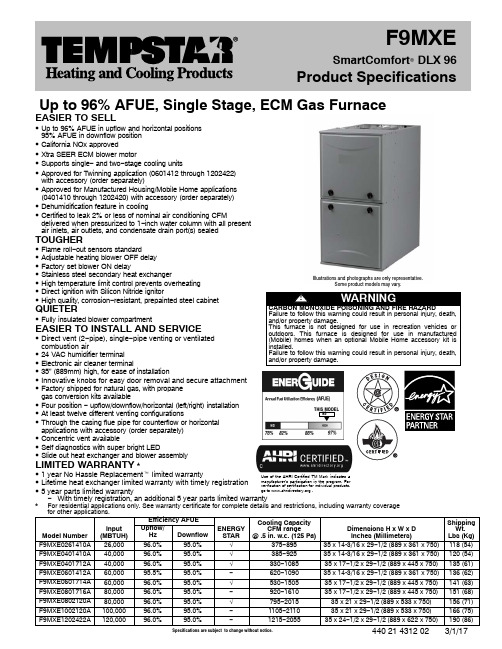
Specifications are subject to change without notice.440 21 4312 02 3/1/17Up to 96% AFUE, Single Stage, ECM Gas FurnaceEASIER TO SELLS Up to 96% AFUE in upflow and horizontal positions95% AFUE in downflow position S California NOx approvedS Xtra SEER ECM blower motorS Supports single − and two −stage cooling unitsS Approved for Twinning application (0601412 through 1202422)with accessory (order separately)S Approved for Manufactured Housing/Mobile Home applications (0401410 through 1202420) with accessory (order separately)S Dehumidification feature in coolingS Certified to leak 2% or less of nominal air conditioning CFMdelivered when pressurized to 1−inch water column with all present air inlets, air outlets, and condensate drain port(s) sealedTOUGHERS Flame roll −out sensors standardS Adjustable heating blower OFF delay S Factory set blower ON delayS Stainless steel secondary heat exchangerS High temperature limit control prevents overheating S Direct ignition with Silicon Nitride ignitorS High quality, corrosion −resistant, prepainted steel cabinetQUIETERS Fully insulated blower compartmentEASIER TO INSTALL AND SERVICES Direct vent (2−pipe), single −pipe venting or ventilatedcombustion airS 24 VAC humidifier terminal S Electronic air cleaner terminalS 35” (889mm) high, for ease of installationS Innovative knobs for easy door removal and secure attachment S Factory shipped for natural gas, with propane gas conversion kits availableS Four position − upflow/downflow/horizontal (left/right) installation S At least twelve different venting configurationsS Through the casing flue pipe for counterflow or horizontal applications with accessory (order separately)S Concentric vent availableS Self diagnostics with super bright LEDS Slide out heat exchanger and blower assembly LIMITED WARRANTY *S 1 year No Hassle Replacement t limited warranty S Lifetime heat exchanger limited warranty with timely registration S 5 year parts limited warrantyIllustrations and photographs are only representative.Some product models may vary.Use of the AHRI Certified TM Mark indicates a manufacturer’s participation in the program. Forverification of certification for individual products,go to .THIS MODEL95−With timely registration, an additional 5 year parts limited warranty*For residential applications only. See warranty certificate for complete details and restrictions, including warranty coverage for other applications.Model NumberInput (MBTUH)Efficiency AFUE ENERGY STAR Cooling Capacity CFM range @ .5 in. w.c. (125 Pa)Dimensions H x W x D Inches (Millimeters)ShippingWt. Lbs (Kg)Upflow/Hz Downflow F9MXE0261410A 26,00096.0%95.0%Ö375−89535 x 14-3/16 x 29−1/2 (889 x 361 x 750)118 (54)F9MXE0401410A 40,00096.0%95.0%Ö385−92535 x 14-3/16 x 29−1/2 (889 x 361 x 750)120 (54)F9MXE0401712A 40,00096.0%95.0%Ö330−108535 x 17−1/2 x 29−1/2 (889 x 445 x 750)135 (61)F9MXE0601412A 60,00095.5%95.0%−620−109035 x 14-3/16 x 29−1/2 (889 x 361 x 750)136 (62)F9MXE0601714A 60,00096.0%95.0%Ö530−150535 x 17−1/2 x 29−1/2 (889 x 445 x 750)141 (63)F9MXE0801716A 80,00096.0%95.0%−920−161035 x 17−1/2 x 29−1/2 (889 x 445 x 750)151 (68)F9MXE0802120A 80,00096.0%95.0%Ö795−201535 x 21 x 29−1/2 (889 x 533 x 750)156 (71)F9MXE1002120A 100,00096.0%95.0%−1105−211035 x 21 x 29−1/2 (889 x 533 x 750)166 (75)F9MXE1202422A 120,00096.0%95.0%−1215−205535 x 24−1/2 x 29−1/2 (889 x 622 x 750)190 (86)F9MXESmartComfort R DLX 96Product SpecificationsMODEL NUMBER IDENTIFICATION GUIDEDIGIT POSITION 123456,7,89,1011,121314 F = Mainline F9M X E0601714A1 N = Entry9 = 90+% AFUE EFFICIENCYM = Multiposition POSITIONA = Modulating ECM Variable Speed BlowerV = ECM Variable SpeedX = ECM Blower (Speed Select)S = Single−stageT = Two−stage TYPEC = CommunicatingE = Extra AFUE EfficiencyT = Two−Stage FEATURE026 = 26,000 BTU/hr040 = 40,000 BTU/hr060 = 60,000 BTU/hr080 = 80,000 BTU/hr100 = 100,000 BTU/hr120 = 120,000 BTU/hr HEAT INPUT14 = 14−3/16”17 = 17−1/2”21 = 21”24 = 24−1/2”CABINET WIDTH08 = 800 CFM10 = 1000 CFM12 = 1200 CFM14 = 1400 CFM16 = 1600 CFM20 = 2000 CFM22 = 2200 CFM NOMINAL MAXIMUM COOLING AIRFLOW @ .5 IN. W.C.SALES (MAJOR) REVISION DIGITENGINEERING (MINOR) REVISION DIGITECM-Electronically Commutated MotorACCESSORIES PART NUMBER IDENTIFICATION GUIDEDIGIT POSITION12345, 6, 78, 910, 11N A H B00701FF N = Non−Branded BRANDINGA = Accessory PRODUCT GROUPH = Heating KIT USAGEA = OriginalB = 2nd Generation MAJOR SERIESProduct Identifier NumberPackage QuantityType of Kit (Example: FF = Filter Kit)440 21 4312 022Specifications subject to change without notice.PHYSICAL DATAUNIT SIZE (NATURAL GASRatings)0261410A0401410A0401712A0601412A0601714A0801716A0802120A1002120A1202422A Input Heat(BTUH)26,00040,00040,00060,00060,00080,00080,000100,000120,000 Output Heat(BTUH)25,00039,00039,00058,00058,00078,00078,00097,000117,000EfficiencyUpflow/HzAFUE % (ICS)96.095.596.0DownflowAFUE % (ICS)95.0Certified Temperature Rise Range ºF (ºC)25−55(14−31)40−70(22−39)35−65(19−36)40−70(22−39)ICS — Isolated Combustion SystemAIRFLOW CAPACITY AND BLOWER DATAUNIT SIZE0261410A0401410A0401712A0601412A0601714ARated External Static Pressure in.w.c.(kPa)Heating.10 (.025).10 (.025).10 (.025).12 (.030).12 (.030) Cooling.5 (.125)Airflow Delivery @ Rated ESP (CFM)Heating6056957059401000 Cooling895925108510901505Cooling Capacity (tons) @ 400, 350 CFM/ton 400 CFM/ton22 2.5 2.5 3.5 350 CFM/ton 2.5 2.5334Direct−Drive Motor Type Electronically Commutated Motor ECMDirect−Drive Motor HP1/31/21/21/23/4 Motor Full Load Amps 4.4 6.8 6.8 6.89.9 RPM Range400−1200600 − 1200Speed Selections5Blower Wheel Dia x Width inches11 x 711 x 711 x 811 x 711 x 8 Air Filtration System Field SuppliedFilter Used for Certified Watt Data NAHA00506FBUNIT SIZE0801716A0802120A1002120A1202422ARated External Static Pressure in.w.c.(kPa)Heating.15 (.038).15 (.038).20 (.050).20 (.050) Cooling.5 (.125)Airflow Delivery @ Rated ESP (CFM)Heating1360136017002125 Cooling1610201521102055Cooling Capacity (tons) @ 400, 350 CFM/ton 400 CFM/ton4555 350 CFM/ton 4.5 5.566Direct−Drive Motor Type Electronically Commutated Motor ECMDirect−Drive Motor HP3/4111 Motor Full Load Amps9.312.312.611.1 RPM Range600 − 1200Speed Selections5Blower Wheel Dia x Width inches11 x 811 x 1011 x 1011 x 11 Air Filtration System Field SuppliedFilter Used for Certified Watt Data NAHA00506FB NAHA00706FBCONTROLSUNIT SIZE0261410A0401410A0401712A0601412A0601714A Gas Connection Size1/2” − NPTBurners (Monoport)22233Gas Valve (Redundant)Manufacturer White Rodgers tMinimum Inlet Gas pressure in. w.c. (kPa) 4.5 (1.1)Maximum Inlet Gas pressure in. w.c. (kPa)13.6 (3.4)Ignition Device Silicon NitrideLimit Control220165180165180 Heating Blower Control(Heating Off−Delay)Adjustable: 90, 120, 150, 180 secondsCooling Blower Control (Time Delay Relay)90 secondsThermostat Connections R, W, Y1, Y/Y2, G, DHUM, CAccessory Connections EAC (115vac); HUM (24vac); 1−stg AC (via Y/Y2)3440 21 4312 02Specifications subject to change without notice.CONTROLS (CONT.)UNIT SIZE0801716A0802120A1002120A1202422A Gas Connection Size1/2” − NPTBurners (Monoport)4456Gas Valve (Redundant)Manufacturer White Rodgers tMinimum Inlet Gas pressure in. w.c. (kPa) 4.5 (1.1)Maximum Inlet Gas pressure in. w.c. (kPa)13.6 (3.4)Ignition Device Silicon NitrideLimit Control170200180160 Heating Blower Control (Heating Off−Delay)Adjustable: 90, 120, 150, 180 secondsCooling Blower Control (Time Delay Relay)90 secondsThermostat Connections R, W, Y1, Y/Y2, G, DHUM, CAccessory Connections EAC (115vac); HUM (24vac); 1−stg AC (via Y/Y2)ELECTRICAL DATAUNIT SIZE0261410A0401410A0401712A0601412A0601714A Input Voltage (Volts−Hertz−Phase)115−60−1Operating Voltage Range Min.−Max.104 − 127Maximum Input Amps Amps 5.17.57.57.610.7 Unit Ampacity Amps7.310.310.310.414.3 Minimum Wire Size AWG1414141414 Maximum Wire Length @ Min Wire Size Feet (M)51 (15.5)36 (11.0)36 (11.0)35 (10.7)26 (7.9) Maximum Fuse/Circuit Breaker(Time−Delay Type Recommended)Amps1515151515 Transformer Capacity24 VAC Output / 40 VAExternal Control Power Available Heating27.9 VA Cooling34.6 VAUNIT SIZE0801716A0802120A1002120A1202422A Input Voltage (Volts−Hertz−Phase)115−60−1Operating Voltage Range Min.−Max.104 − 127Maximum Input Amps Amps10.113.113.512.0 Unit Ampacity Amps13.517.317.715.9 Minimum Wire Size AWG14121212 Maximum Wire Length @ Min Wire Size Feet (M)27 (8.2)33 (10.1)32 (9.8)36 (11.0) Maximum Fuse/Circuit Breaker (Time−Delay Type Recommended)Amps15202020 Transformer Capacity24 VAC Output / 40 VAExternal Control Power Available Heating27.9 VA Cooling34.6 VAMINIMUM CLEARANCES TO COMBUSTIBLE MATERIALS FOR ALL UNITSPOSITION CLEARANCE In(mm)REAR0 FRONT (Combustion air openings in furnace and in structure) 1 (25)Required for service*24 (610)All Sides of Supply Plenum*1 (25)Sides0Vent0Top of Furnace 1 (25)* Consult your local building codes.FURNACE SIZEA B C DSHIP WT.LB (KG) CABINETWIDTHOUTLETWIDTHBOTTOMINLET WIDTH AIR INTAKE026141014−3/16 (361)12−1/2 (319)12−9/16 (322)7−1/8 (181)118 (54) 040141014−3/16 (361)12−1/2 (319)12−9/16 (322)7−1/8 (181)120 (54) 040171217−1/2 (445)15−7/8 (403)16 (406)8−3/4 (222)135 (61) 060141214−3/16 (361)12−1/2 (319)12−9/16 (322)7−1/8 (181)136 (62) 060171417−1/2 (445)15−7/8 (403)16 (406)8−3/4 (222)141 (63) 080171617−1/2 (445)15−7/8 (403)16 (406)8−3/4 (222)151 (68) 080212021 (533)19−3/8 (492)19−1/2 (495)10−1/2 (267)156 (71) 100212021 (533)19−3/8 (492)19−1/2 (495)10−1/2 (267)166 (75) 120242224−1/2 (622)22−7/8 (581)23 (584)12−1/4 (311)190 (86)440 21 4312 024Specifications subject to change without notice.5440 21 4312 02Specifications subject to change without notice.AIR DELIVERY − CFM (with filter)UNIT SIZE RETURN-AIRCONNECTIONSPEEDTAPS2,3EXTERNAL STATIC PRESSURE (IN.W.C.)0.10.20.30.40.50.60.70.80.9 1.00261410SIDE/BOTTOMBlack10451010975935895855810760715670 Yellow820770730680630585530480435385 Orange655600550495435385335265−6−6 Blue605545490435375335255−6−6−6 Red480415360305235−6−6−6−6−60401410SIDE/BOTTOMGray112010801030980925875820760690630 Yellow880845810780740710680640615570 Blue695665620575535495455420370280 Orange640595540495460420370310260230 Red570525475425385330255220- 6- 60401712SIDE/BOTTOMGray125512201175113010851040990940880825 Yellow940905870840805770735695665630 Blue705670630575540500455410380325 Orange580535480425380335290235- 6- 6 Red555485425375330280215- 6- 6- 60601412SIDE/BOTTOMGray126512251185114010901030975920850760 Yellow11151085106010301000970930880810715 Orange1000970940910880845815770735695 Blue945915885855820785745705675635 Red7707407006606205755405004554150601714SIDE/BOTTOMGray1720167016201565150514401375129512201135 Yellow1325128512551220118511451115107510401000 Blue1010970925875835785745690660620 Orange11601115108010451000960920875840785 Red7857156555955304904353853402850801716SIDE/BOTTOMGray1810177017201665161015401475140013151235 Yellow1535150014751435140513701340131012451160 Blue1380134013051270124012001165113010901050 Orange11801130109510601015975935895850800 Red1100104510109709208858457907456900802120BOTTOM orTWO-SIDES 4,5Gray2290222521552090201519301845175016401515 Yellow1810176017251685164016001555152014801415 Blue13851340128512401200114010901050995950 Orange1560152014751430138513351295124012001150 Red10559859108607957506806155654951002120BOTTOM orTWO-SIDES 4,5Gray2340229522502195211020301935183517251605 Yellow1950190018551800175517051655160515601485 Blue1750170016501605155515001455139513501300 Orange1570152014601410135013001240119511401095 Red13501280122511551105104510009508958301202422BOTTOM orTWO-SIDES 4,5Gray2275223021852130205519501825171016101500 Yellow1875182017701720166016001550150514501390 Blue2170212520752025197519001790169515901470 Orange314751420135012801215116511051050995930 Red31625156515051445138513251275122511701130NOTE:1.A filter is required for each return−air inlet. Airflow performance includes a 3/4 in. (19 mm) washable filter media such as contained in factory−author-ized accessory filter rack. See accessory list. To determine airflow performance without this filter, assume an additional 0.1 in. W.C. available external static pressure.2.ADJUST THE BLOWER SPEED TAPS AS NECESSARY FOR THE PROPER AIR TEMPERATURE RISE FOR EACH INSTALLATION.3.Shaded areas indicate that this airflow range is BELOW THE RANGE ALLOWED FOR HEATING OPERATION. THESE AIRFLOW RANGES MAYONLY BE USED FOR COOLING.4.Airflow over 1800 CFM require bottom return, two−side return, or bottom and side return. A minimum filter size of 20” x 25” is required.5.For upflow applications, air entering from one side into both the side of the furnace and a return air base counts as a side and bottom return.6.The ”−” entry indicates an unstable operating condition.440 21 4312 026Specifications subject to change without notice.ACCESSORIESPART NUMBER COMPONENT NAME DESCRIPTION026141004014100401712060141206017140801716080212010021201202422 NAHB00101CT EXTERNAL TRAP KIT CONENSATE TRAP X X X X X X X X X NAHA00110DA DRAIN ACCESSORY1/2” CPVC TO 3/4” PVC (10 PACK)X X X X X X X X XNAHA002CVVENT TERMINATION KIT 2” CONCENTRIC VENT X X X X X X X XNAHA001CV3” CONCENTRIC VENT X X X X X X NAHA00101VC INTERNAL VENT KIT THROUGH THE CABINET X X X X X X X X XNAHA00301VT DIRECT VENTTERMINATION KIT 2” BRACKET X X X X X X X XNAHA00401VT3” BRACKET X X X X X XNAHA00101CK INLET AIR PIPE COUPLING COUPLING FORPOLYPROPYLENE VENTSYSTEMSX X X X X X X X XNAHA00101HV HORIZONTALINSTALLATION KITTRAP GROMMET (DIRECT VENTAPPLICATION ONLY)X X X X X X X X XNAHA00101HH FREEZE PROTECT KIT CONDENSATE DRAIN LINE -TAPEX X X X X X X X XNAHA00201HH CONDENSATE FREEZEPROTECT KITCONDENSATE TRAP WITH HEATPADX X X X X X X X XNAHA01101SB FLOOR BASE KIT COMBUSTIBLE FLOOR X X X X X X X X XNAHD00901LP*GAS CONVERSION KIT NATURAL TO PROPANE X X X X X X X XNAHD00901NG*PROPANE TO NATURAL X X X X X X X XNAHA01201LP*GAS CONVERSION KIT NATURAL TO PROPANE XNAHA01201NG*PROPANE TO NATURAL XNAHA00101MH*MANUFACTURED HOME KIT GAS CONVERSION KIT X X X X X X X XNAHA00701WK TWINNING KIT OPERATION OF TWO IDENTICALSIZE MODEL FURNACESX X X X X XNAHA00506FB†WASHABLE FILTER PACK WASHABLE FILTER1” X 16” X 25” (6 PACK)X X X X X XNAHA00706FB WASHABLE FILTER1” X 24” X 25” (6 PACK)X X XNAHB00501FFEXTERNAL BOTTOMFILTER RACK 14” X 25” WASHABLE FILTERINCLUDEDX X XNAHB00601FF 17-1/2” X 25” WASHABLE FILTERINCLUDEDX X XNAHB00701FF 21” X 25” WASHABLE FILTERINCLUDEDX XNAHB00801FF 24-1/2” X 25” WASHABLE FILTERINCLUDEDXNAHA01001FF SIDE FILTER RACK(NOT ADJUSTABLE)16” X 25” RACK - FILTER NOTINCLUDEDX X X X X X X X XNAHB00101CACOIL ADAPTER KIT WITH NO OFFSET X X X X X X X X XNAHB00201CA WITH SINGLE OFFSET X X X X X X X X X NAHB00301CA WITH DOUBLE OFFSET X X X X X X X X XNAHA01401RARETURN AIR KIT 14-3/16” WIDE X X XNAHA01701RA17-1/2” WIDE X X XNAHA02101RA21” WIDE X XNAHA02401RA24-1/2” WIDE XNAHA001NK CONDENSATENEUTRALIZER KITNEUTRALIZES CONDENSATE X X X X X X X X XX Accessory available†Suitable for side return filter rack and 17 inch external bottom filter rack.*Factory authorized and field installed. Gas conversion kits are CSA recognized.Part Number Gas Type Orifice Size Part Number Gas Type Orifice Size Part Number Gas Type Orifice Size 1185612Natural421183809Natural461184256Propane54 1176928Natural431185613Natural471185615Propane55 1185574Natural441185614Natural481185616Propane56 1177213Natural451185617Propane 1.25 mm1185618Propane 1.30 mmSpecifications subject to change without notice.7440 21 4312 02Copyright 2017 International Comfort ProductsLewisburg, Tennessee 37091 USA440 21 4312 028Specifications subject to change without notice.。
- 1、下载文档前请自行甄别文档内容的完整性,平台不提供额外的编辑、内容补充、找答案等附加服务。
- 2、"仅部分预览"的文档,不可在线预览部分如存在完整性等问题,可反馈申请退款(可完整预览的文档不适用该条件!)。
- 3、如文档侵犯您的权益,请联系客服反馈,我们会尽快为您处理(人工客服工作时间:9:00-18:30)。
Rinnai(Product NO:ZTD90F-F)
Instruction manualfor tableware sterilize
◆The power button:
with the machine off,a long press the power button for 2 seconds,the screen lights is on, system will enter the standby.
in standby mode,a long press the power button for 2 seconds,system will enter shutdown.
Under working conditions,a long press the power button for 2 seconds,allthe buttons returns unlock,you can press the function Keys again to change the function you need.
◆The upper drawer button:in standby mode, press it, you will select “ozone ultraviolet rays”.
◆The lower drawer button:in standby mode,press it,you will select “high temperature”.
Function table 1
methodappropriately,afterthat,please select the drawer that need to be dry by pressing “The upper drawer button”or/and“The lower drawer button”.
Function table 2
start(from 1 hour to 9 hours ).
Please note:◆When the power is turn on, the screen lights is off automatically after 2 seconds.
◆in setting status,the time interval of the continuous pressing button should not exceed 10 seconds.
◆Under working conditions,all the function keys is locked.if you want to change thefunction,firstly,a long press the power button for 2 seconds, after the buttons returns unlock you can reset it according to function tables .During lower drawer is working in high temperature, if the temperature is above 55 degrees,it cannot be reset,but you can cancel high temperature(the door still is locked),only the temperature drops to below 55 degrees you can open the door, and then you can reset it.
◆During reservation,the function you have selected will not be changed after you open or lock the doors. After reaching the time of the reservation,your reservation will be cancelled automatically when you leave the door open.。