Testo_Smart-Probe_Chinese_201602
Probe_Assistant使用简介

Probe、Assistant 使用简介
C&Wi售前网络规划部
四川移动TD-LTE项目组培训材料 2013年9月14日
HUAWEI TECHNOLOGIES CO., LTD.
Huawei Confidential
掌握测试和数据分析的基本知识 掌握Probe软件测试方法 掌握Assistant软件数据分析方法 了解一般问题的定位和解决方法
Huawei Confidential
Huawei GENEX Series
GENEX Nastar Network Performance Analysis System
GENEX Probe GENEX Assistant Test & Post-Process Tools
Downlink + Uplink
性能/配置/CHR/用户 跟踪/RTWP/
工程参数等综合分析
GENEX
Nastar
集成多种优化/规划辅助工具
分析结论共享
GENEX Probe Qualcomm
HUAWEI RNC
多种测试数据
GENEX Assistant
iManagerTM M2000 获取测试数据
eNB
eNB
GENEX Probe
9.按分析集查看分析报告
10.事件下钻进行问题定位
11.查看专题分析结果 查看KPI/IE
组合查询
新建工程
配置工程
导入工参
导入地图
选择导入的数据 设置监控目录
执行导入分析
自动导入分析
建立分析集 分析集
以分析集为单位进行查 看KPI,报告,专题等
HUAWEI TECHNOLOGIES CO., LTD.
ICP DAS ET-7065 Ethernet Remote I O 快速入门指南说明书

ET-70656 Channel Photo-Mos Relay Output and 6 ChannelDigital Input Data Acquisition ModuleQuick Start GuideThe ET-7065 is a web-based Ethernet I/O module. It features a built-in web server which allows configuration, I/O monitoring and I/O control by simply using a regular web browser. Remote control is as easy as you surfing the Internet. With the web HMI function, noprogramming or HTML skills are needed. Users can create dynamic and attractive web pages for I/O monitoring and I/O control. The ET-7065 offers easy and safely access for users from anytime and anywhere! In addition, the ET-7065 also supports Modbus/TCP protocol that makes perfect integration for ET-7000 series to SCADA software. The ET-7000 series aredesigned for applications to industrial monitoring and measurement; therefore, we have made it toughly enough to survive the harsh and rough environment. The module contains 2-wayisolation from noise and surges, one for digital inputs and the other for Ethernet. The ET-7000 has got a wide range of power input (10~30VDC) and operating temperature (-25°C~+75°C).What’s in the box?In addition to this guide, the package includes the following items:ET-7065 Module Software Utility CD- ET-7065 Websitehttps:///et_7065.html- ICP DAS USA Website /Phone : 1-310-517-9888 Email: ********************Tech Support:*******************21-----------------------------------------------------------Configuring Boot ModeInit mode: For configuration. After booting, ET-7065 will not run thedefault firmware and cannot surf the internet. Use this mode toupdate MiniOS7 image.Normal mode: For normal working. After booting, ET-7065 will run thedefault firmware and can use all ET-7065 functions.---------------------------------------------------------------------------------- Connecting to Network, PC and PowerThe ET-7065 is equipped with an RJ-45 Ethernet port for connection to an Ethernet hub/switch and PC.3 4 ---------------------------------------------------------------------------------Installing the MiniOS7 UtilityThe MiniSO7 Utility can be obtained from companion CD or our site: CD:\Napdos\minios7\utility\minios7_utility\ /minios7utility.htmlAfter the installation has been completed, there will be a new short-cut for MiniOS7 Utility on the desktop.----------------------------------------------------------------------------------Using MiniOS7 Utility to Assign a New IPThe ET-7065 are Ethernet devices, which comes with a default IP address, therefore, you must first assign a new IP address to the ET-7065. The factory default IP settings are as follows:Double-click the MiniOS7 Utility shortcut on your desktop.After pressing F12 or choosing Search from Connection menu, the MiniOS7 Scandialog will appear, that will display a list of all the MiniOS7 modules on your network.See the status tip, waiting for the search to be done.Choose the module name for fields in the list, and then choose IP setting from the toolbar.After completing the settings, press the Yes button in the Confirm dialog box to exit the procedure.56---------------------------------------------------------------------------------- Enabling Adobe Flash Player in Your BrowerYour browser must support Adobe Flash Player and have it enabled in order to use theET-7065 web site.If you do not have it installed, please go to the following website and install it.The Adobe Flash Player Download Center:/flashplayer/---------------------------------------------------------------------------------- Go to the ET-7065 Web Site to Check out FunctionsThe ET-7065 contains an advanced web configuration system that provides users with accessET-7065 applications through a standard web browser.Make sure the switch placed in the“ Normal” p osition.Then reboot ET-7065Please use a standard internet browser to view the ET-7065 webpage, such as MozillaFirefox or Internet Explorer…etc.If you haven’t changed the default IP address of the ET-7065, please refer to “4. UsingMiniOS7 Utility to Assign a New IP” to configure it.After entering the IP address, the logindialog box will appear and prompt you toenter your username and password.The factory default user name and passwordare as follows (Case sensitive) :After logging into the ET-7065 web site, the welcome page will appear.Under the Main Menu, expand the Web HMI, andthen select the Web HMI option to check the values of the data acquisition.。
LTE测试软件Probe说明

LTE软件使用说明1.软件安装目前测试LTE站点主要是用Probe软件,下面对此软件的安装,使用做一个简单的介绍。
由于本人刚开始使用此软件,对此软件还不是很精通,如有不妥的地方,望各位不吝赐教,不胜感激。
1.1安装概述要使用Probe的各种功能,必须正确的安装Probe软件、GENEX Shared组件。
1.2检查安装环境为了Probe软件的正常安装和运行,用户机器配置需要具备的条件如表1所示。
表1安装环境1.3拷贝软件拷贝如图1安装文件:图12019-7-25 江苏邮电建设工程有限公司第1页, 共46页1.4安装GENEX Shared组件主程序安装过程会自动调用组件包安装程序。
卸载Probe主程序并不会同时卸载GENEX Shared组件,这是为了保证GENEX系列其他产品可以正常运行。
对于安装过Probe的机器,再次安装Probe时可以跳过GENEX Shared组件的安装,如果安装的是Probe升级版本时,建议同时再次安装GENEX Shared组件,因为GENEX Shared组件可能也需要升级。
安装GENEX Shared组件的步骤如下:步骤1打开图1中的Probe文件夹中的GENEX Shared安装文件,如图2所示,双击“setup.exe”文件,启动安装界面。
图2步骤2 单击“Next”。
步骤3 在协议确认对话框中,单击“Yes”。
步骤4 安装完成后,单击“Finish”。
GENEX Shared安装程序自动安装了以下组件:MapX组件:提供对Map处理的支持。
TeeChart组件:图标界面开发控件。
OWC组件:发布电子表格、图表与数据库到Web的一组控件。
硬件狗加密锁驱动:用于维护版本的授权。
----结束2019-7-25 江苏邮电建设工程有限公司第2页, 共46页1.5安装Probe软件安装Probe软件的步骤如下(安装新版本前需要卸载旧版本,并且建议删除旧的工程文件)。
步骤1 打开如图3所示的probe文件中的硬狗版软件安装文件,双击“setup.exe”,启动安装界面。
5GPHU操作指导书
5GPHU-Smart&操作指导书湖州电信项目2020-4-35GPHU-Smart&操作指导书目录1.测试配置 (2)1.1测试业务配置 (2)1.2报告配置 (8)2.导入测试工参 (10)2.1上传测试工参 (10)3.GC端新建单验任务 (12)3.1新建任务 (12)4.任务的分配与下发 (14)4.1任务的分配与下发 (14)5.手机端PHU操作 (14)5.1工程下载 (14)5.2任务接受 (15)5.3开始测试 (15)5.4指标自检 (16)5.5勘测功能 (17)5.5.1勘测APP站点核查 (17)5.5.2勘测APP-勘测照片 (18)5.6输出报告 (19)1.测试配置1.1测试业务配置测试配置是在GC端的配置测试计划,设置数据命名规则及相关的手机侧指标信息显示情况。
届时,手机端的配置执行。
流程:登录GC进入路测作业数字化测试测试计划登录GC:https:///genexcloud/portal/login.do进入路测作业数字化APP:测试:测试配置:添加定点测试业务:在“测试配置”中,趼Group,选择对应的制式(以NR为例),点击“测试计划”。
默认会展示定点测试的所有测试业务,根据现场测试需求选择相应的测试业务,将不需要的测试业务进行删除(也可保留,手机端支持测试业务选择)。
点击右侧“参数设置”中的"编辑”,即可对测试计划进行设置。
新增测试业务:测试业务配置:配置上传配置:下载配置:ATTACH配置:移动测试配置:上传配置:下载配置:1.2报告配置报告配置:是对测试Log、速率截图名称进行设置,并选择相应的报告模板及扩展工参, 该操作是为了将测试数据直接从手机端上传至平台输出报告。
在报告配置页面先选择相应的报告模板,再选择扩展工参(扩展工参模板在平台上下载后,填写完整,上传。
)其次,分别在定点测试、移动测试、速率截图中设置相应的数据名称。
smartbits 600B网络性能分析仪操作规程

Smartbits 600B网络性能分析仪操作规程1使用说明1.1 测试4大指标吞吐量Throughput、延时Latency、包丢失Packet Loss、背到背Back to Back。
1.2 难题假设为了降低操作难度,电脑、SmartBits 600的常规配置,假设已由技术支持人员进行完毕。
如:SmartBits 600的IP地址已设好为: 192.168.0.100;控制电脑的IP地址已设好为:192.168.0.xxx ;(xxx可取任何值,但不能是100)……。
当操作人员发现不正常时,可请求技术支持。
1.3 SmartBits 600B配置LAN-3100A 插卡1块;SmartApplications ,SmartWindows工具软件各1份。
2 测试系统搭建搭建测试系统如图1所示。
图1 电脑、smartbit200、特测系统连接图2.1 连接smartbit600B 、控制电脑下面提到的特测系统,可用我公司的EOC网桥与终端,也可以是交换机。
操作:选择smartbit600B背面板的10/100BASE-T以太口与控制电脑的网卡以太口连接。
2.2 连接SmartBits 600B、被测系统。
下面提到的“被测系统的任一个RJ45口”,不含网管RJ45口。
将LAN-3100A卡的任意两个口分别与被测设备输入输出口相连接。
操作:将SmartBits 600B前面板的RJ45口1、2,通过网线,分别与被测设备的输入输出口(RJ45口)连接。
3 测试配置步骤3.1 SmartApp打开、建立连接参照下面图2所示的测试主界面。
操作:打开电脑、smartbit200、被测设备电源。
单击[开始]—[程序]—[smartbits Applications]—[SmartApplications] 。
首先修改电脑本身的IPD地址:192.168.0.xxx(xxx不能为100),子网掩码为:255.255.255.0。
004 华为Probe使用指导2.0

江苏邮电建设工程有限公司第十分公司Probe使用文档华为产品刘毅2012-8-12目录1.软件安装 (5)1.1概述 (5)1.2GENEX Probe 简介 (5)1.3GENEX Probe 软件安装 (5)1.4GENEX Probe 软件狗License升级 (6)2.软件界面 (8)2.1概述 (8)2.2软件主界面介绍 (8)2.3按键介绍 (9)2.3.1Project按键介绍 (9)2.3.2Logfile按键 (10)2.3.3Configuration按键 (11)2.3.4View按键 (12)2.3.5Test 按键 (13)2.3.6Help按键 (14)3.LTE测试指导 (15)3.1概述 (15)3.2测试条件准备 (15)3.2.1明确测试任务 (15)3.2.2测试软件的检测 (15)3.2.3测试路线的选择 (15)3.3测试条件确认 (15)3.4测试操作 (16)3.4.1CPE测试操作流程 (16)3.4.1.1测试软件的准备 (16)3.4.1.2测试步骤 (17)3.4.2TUE测试操作流程 (34)3.4.2.1测试软件的准备 (34)3.4.2.2测试步骤 (34)4.probe数据分析及后处理 (42)4.1测试数据回放 (42)4.2数据分割 (43)4.3测试数据导出 (44)4.4用Probe进行室内测试方法 (46)4.5Probe的强制功能测试 (50)5.Assistant操作方法介绍 (52)5.1数据导入 (52)5.1.1新建工程 (52)5.1.2导入路测数据 (52)5.1.3导入工参 (54)5.1.4导入地图 (56)5.2数据分析 (57)5.2.1基本分析 (57)5.2.2单小区覆盖分析 (62)5.2.3拉线图分析 (63)5.2.4钻取分析结果 (64)5.2.5导出LTE UE报告 (64)5.2.6Query(查询)功能 (65)5.3数据后处理 (67)5.3.1覆盖分析 (68)5.3.1.1RSRP (68)5.3.1.2SINR (70)5.3.1.3上下行吞吐率 (70)5.3.1.4PCI分布 (71)5.3.1.5各扇区PCI覆盖图 (72)5.3.1.6KPI及事件分析 (73)6.附录 (77)6.1TCP窗口设臵 (77)6.2TCP速率的影响因素 (77)6.3TCP窗口设臵理论分析 (77)6.4接收方的接收窗口设臵方法 (78)6.4.1Windows XP、2003系统 (78)6.4.2Vista系统 (79)6.4.3Win7系统 (80)6.4.4接收方的接收窗口设臵注意事项 (80)6.5发送方的发送缓存设臵方法 (81)6.6UE2.0测试中常见问题解答 (83)6.6.1电脑中无法找到USB网卡的连接属性 (83)6.6.2OMT、Probe无法连接上Test UE (83)6.6.3通过OMT信令获取业务PC IP的方法 (83)6.6.4入网后无法Ping通FTP服务器,但是本地地址显示连接状态正常 (85)6.6.5Probe不显示RSRP、PCI的信息 (85)6.6.6PIN码查询失败 (85)6.6.7UE无法接入小区 (85)6.6.8OMT消息过滤方法 (86)6.6.9OMT中关键事件跟踪窗口 (86)6.7Hisi终端E398s常见问题解答 (87)6.7.1海思终端无法自动激活网卡 (87)6.7.2海思终端的MobilePartner无法设臵apn (88)6.7.3无法入网的时候怎么办? (90)6.7.4如何检查HisiDongle连接状态 (90)6.8Probe+E397/E392路测方法 (91)6.8.1E397/E392终端简介 (91)6.8.2应用Mobile Partner配臵E397/E392方法简介 (92)6.9Probe相关设臵 (94)6.9.1Probe连接E397/E392测试方法简介 (94)6.9.2E397/E392相关指标参数 (97)1.软件安装1.1概述本章将介绍如下内容●GENEX Probe 简介●GENEX Probe 软件安装1.2GENEX Probe 简介GENEX Probe是Huawei GENEX网规网优解决方案的重要组成部分,定位为路测前台软件,负责数据的采集、实时显示、记录,常与路测后处理软件GENEX Assistant配合使用;GENEX Probe的功能根据用户自选上报周期实时显示空口参数、测量指标地理化显示测量指标,直观展现网络质量通过配臵测试计划自动执行测试任务记录测试数据,为分析网络性能或问题定位提供依据测试数据回放,再现测试时刻场景1.3GENEX Probe 软件安装按如下步骤安装GENEX Probe:进入Probe文件夹中的GENEX Shared,安装GENEX Shared,双击“setup.exe”文件;等待片刻,弹出“GENEX Shared – InstallShield Wizard”对话框。
中国移动智能家庭网关软探针技术规范v1.0.0

中国移动通信企业标准QB-╳╳-╳╳╳-╳╳╳╳中国移动智能家庭网关软探针技术规范T e c h n i c a l S p e c i f i c a t i o n f o rI n t e l l i g e n t H o m e G a t e w a y S o f t P r o b e版本号:1.0.0╳╳╳╳-╳╳-╳╳发布╳╳╳╳-╳╳-╳╳实施目录1. 前言 (3)2. 范围 (3)3. 规范性引用文件 (3)4. 术语、定义和缩略语 (3)5. 智能家庭网关软探针系统结构 (4)6. 智能家庭网关软探针信息采集功能 (5)6.1. 网关信息采集 (5)6.1.1. 网关基本信息 (5)6.1.2. 网关状态信息 (6)6.1.3. WAN口流量信息 (7)6.1.4. 下挂设备信息 (7)6.1.5. POTS信息 (8)6.1.6. PON口状态 (8)6.1.7. 周边WIFI信息 (8)6.2. 网络质量信息采集 (9)6.2.1. 业务基本信息 (9)6.2.2. TCP连接信息 (10)6.2.3. HTTP连接信息 (10)6.2.4. DNS解析信息 (11)6.2.5. Web页面访问信息 (11)6.2.6. 即时通讯信息 (11)6.2.7. 游戏信息 (12)6.2.8. 视频信息 (12)7. 智能家庭网关软探针告警功能 (12)7.1. DNS告警 (12)7.2. TCP连接告警 (13)7.3. HTTP连接告警 (13)7.4. HTTP下载告警 (14)7.5. 视频卡顿告警 (15)7.6. 即时通信/游戏告警 (15)8. 智能家庭网关软探针网络探测功能 (15)8.1. 网络诊断功能 (16)8.1.1. 互联网连通性测试 (16)8.1.2. 互联网路由跟踪测试 (16)8.1.3. 互联网FTP上/下载测试 (17)8.1.4. 互联网HTTP文件测试 (18)8.2. 业务网络质量测试功能 (18)8.2.1. 网页访问质量测试 (18)8.2.2. 互联网视频质量测试 (19)8.2.3. 网络游戏使用质量测试 (20)9. 智能家庭网关软探针数据传输要求 (20)9.1. 概述 (20)9.2. 启动上报 (21)9.3. 周期上报 (21)9.4. 实时上报 (22)9.5. 告警 (22)9.6. 探测任务下发 (22)10. 智能家庭网关软探针技术要求 (23)10.1. 功能性要求 (23)10.2. 可靠性要求 (23)10.3. 安全性要求 (24)10.4. 可维护性要求 (24)1.前言本规范旨在描述智能家庭网关软探针的技术规范,用以规范软探针监测平台(省级数字家庭管理平台-软探针前置机)和智能家庭网关软探针的对接,保证采集数据的一致性,以及传输方式的一致性。
SmartBits600测试指导书

资料编码产品名称使用对象产品版本编写部门资料版本SmartBits600测试指导书拟制:日期:审核:日期:审核:日期:批准:日期:华为技术有限公司版权所有侵权必究修订记录目录1SmartBits600仪表使用 (5)1.1仪表概述 (5)1.2Smartbits600 面板介绍 (5)1.2.1Smartbits600前视图 (5)1.2.2Smartibits600后视图 (6)1.3Smartbits600基本操作 (6)1.3.1SmartBits的IP地址配置方法 (6)1.3.2SmartWindow应用程序操作介绍 (6)1.3.3SmartApplications应用程序操作介绍 (11)2SmartBits600测试指导 (14)2.1功能测试 (14)2.1.1长期丢包测试 (14)2.1.2流控功能测试 (16)2.2指标测试..... . (18)2.2.1吞吐量测试 (18)2.2.2时延测试 (21)2.2.3丢包率测试 (24)关键词:SmartBits600测试以太网网络摘要:SmartBits系列测试仪是由NetCom System公司生产的,专门测试和分析网络性能的一种工具,SmartBits通过各种SmartCard的组合来实现对网络的测试、仿真和分析。
SmartBits600测试仪是其中的便携式设备,与SmartBits-6000B系统兼容,最多可插入两块测试卡,支持16个10/100M以太网端口。
缩略语清单:无。
参考资料清单无。
SmartBits600E测试指导书1 SmartBits600仪表使用1.1 仪表概述SmartBits系列测试仪是由NetCom System公司生产的,专门测试和分析网络性能的一种工具,SmartBits通过各种SmartCard的组合来实现对网络的测试、仿真和分析。
SmartBits600测试仪是其中的便携式设备,与SmartBits-6000B系统兼容,最多可插入两块测试卡,支持16个10/100M以太网端口。
DCS-3600命令手册-02_端口操作命令
目录第1章端口配置命令..................................................................1-11.1 以太网端口配置命令........................................................................1-11.1.1 bandwidth..............................................................................................1-11.1.2 clear counters.......................................................................................1-11.1.3 flow control...........................................................................................1-11.1.4 interface ethernet..................................................................................1-21.1.5 loopback................................................................................................1-21.1.6 mdi.........................................................................................................1-21.1.7 name......................................................................................................1-31.1.8 negotiation............................................................................................1-31.1.9 rate-suppression...................................................................................1-31.1.10 rate-violatoin.......................................................................................1-41.1.11 show interface.....................................................................................1-41.1.12 shutdown.............................................................................................1-61.1.13 speed-duplex.......................................................................................1-61.1.14 combo-forced-mode...........................................................................1-71.1.15 virtual-cable-test.................................................................................1-8第2章端口隔离功能配置命令....................................................2-12.1 isolate-port group...........................................................................2-12.2 isolate-port group switchport interface........................................2-12.3 show isolate-port group.................................................................2-2第3章端口环路检测功能命令....................................................3-13.1 loopback-detection control............................................................3-13.2 loopback-detection specified-vlan................................................3-13.3 loopback-detection interval-time...................................................3-23.4 loopback-detection control-recovery timeout..............................3-23.5 show loopback-detection...............................................................3-23.6 debug loopback-detection.............................................................3-3第4章 ULDP命令.......................................................................4-14.1 uldp enable......................................................................................4-14.2 uldp disable.....................................................................................4-14.3 uldp hello-interval...........................................................................4-14.4 uldp aggressive-mode....................................................................4-24.5 uldp manual-shutdown...................................................................4-24.6 uldp reset.........................................................................................4-24.7 uldp recovery-time..........................................................................4-24.8 show uldp........................................................................................4-34.9 debug uldp fsm interface ethernet................................................4-34.10 debug uldp error...........................................................................4-34.11 debug uldp event..........................................................................4-44.12 debug uldp packet........................................................................4-44.13 debug uldp interface ethernet.....................................................4-4第5章 LLDP功能命令................................................................5-15.1 lldp enable.......................................................................................5-15.2 lldp enable(端口).........................................................................5-15.3 lldp mode.........................................................................................5-15.4 lldp tx-interval.................................................................................5-25.5 lldp msgTxHold...............................................................................5-25.6 lldp transmit delay..........................................................................5-25.7 lldp notification interval.................................................................5-35.8 lldp trap............................................................................................5-35.9 lldp transmit optional tlv................................................................5-35.10 lldp neighbors max-num..............................................................5-45.11 lldp tooManyNeighbors................................................................5-45.12 show lldp.......................................................................................5-45.13 show lldp traffic............................................................................5-55.14 show lldp interface ethernet........................................................5-55.15 show lldp neighbors interface ethernet......................................5-65.16 show debugging lldp....................................................................5-65.17 debug lldp......................................................................................5-65.18 debug lldp packets.......................................................................5-75.19 clear lldp remote-table..................................................................5-7第6章 Port Channel配置命令...................................................6-16.1 debug lacp.......................................................................................6-16.2 port-group.......................................................................................6-16.3 port-group mode.............................................................................6-16.4 interface port-channel....................................................................6-26.5 show port-group.............................................................................6-2第7章 JUMBO配置命令............................................................7-17.1 jumbo enable..................................................................................7-1第1章 端口配置命令1.1 以太网端口配置命令1.1.1 bandwidth命令:bandwidth control < bandwidth > {transmit | receive | both}no bandwidth control功能:打开端口的带宽限制功能;本命令的no操作为关闭端口的带宽限制功能。
NCS-TO型OPC网闸产品手册

工业网络安全防护网关NCS-TO型OPC网闸产品手册上海汉序信息技术有限公司目录1、产品介绍 (3)2、产品订购 (4)3、产品清单 (5)4、产品安装 (5)5、缺省配置 (6)6、配置调试 (6)6.1 准备工作 (6)6.2 OPC DCOM通用配置 (7)6.3 OPC Server配置 (16)6.3.1 账户配置 (16)6.3.2 DCOM配置 (16)6.3.3 安全配置 (17)6.3.4 其他配置 (18)6.4 OPC Gate配置 (19)6.5 OPC Client配置 (21)6.5.1 账户配置 (21)6.5.2 DCOM配置 (21)7、故障维护 (23)8、保修服务 (24)1、产品介绍NCS-TO型OPC网闸是一款专门为企业过程控制系统和管理信息系统之间进行物理隔离并传输过程数据而开发的网络安全隔离设备,外观如下图所示:产品主要功能特点有:1)OPC服务器:与DCS、PLC、SCADA等系统连接采集实时数据,通过安全隧道、校验后封装成OPC Server工业标准通讯接口,提供给上层应用系统,如实时数据库系统、MIS、MES系统2)安全隔离:当OPC网闸为上层系统提供实时数据时,它一般位于自动化控制系统和上层系统之间,由于OPC网闸采用了内置安全数据传输隧道、校验技术,可实现自动化控制系统和上层系统之间的有效安全隔离3)该产品操作系统、数据采集程序等均固化,不可修改。
一旦被修改,重新启动后,自动恢复到初始状态,可防止病毒以及黑客软件攻击4)结构先进、安装方便,可以直接安装在标准机柜中5)内置2个100M以太网口6)支持硬件看门狗7)高数据吞吐量,可达10000Tags/s8)支持标签数有:5K - 50K Tags9)支持远程配置10)输入电压:220VAC11)功率:60W12)工作温度:-10-60℃,适宜温度:0-50℃典型应用系统拓扑图如下图所示。
2、产品订购3、产品清单4、产品安装1)检查包装是否完整,配件是否齐全;2)检查安装环境,适宜的环境应干净、通风良好、温度为0-50℃;3)安装耳朵,牢固地固定在机架上;4)主机外壳接地;5)检查220VAC是否正常,主机电源线连接;6)Trusted端及Distrusted端网络接入。
启扬科技 EZ9260-EVB Linux 测试手册说明书

EZ9260-EVB Linux 测试手册版本号v2.82011-11-20杭州启扬智能有限公司版权所有QIYANG TECHNOLOGY Co., LtdCopyright Reserved目录前言 (3)一、准备工作 (4)1.1配置 (4)1.2主板要求 (4)1.3启动主板 (4)二、主板测试 (5)2.1蜂鸣器测试 (5)2.2 GPIO测试 (6)2.3 RTC测试 (6)2.4音频测试 (7)2.5串口测试 (8)2.6 EBI总线测试 (9)2.7 USB Host接口测试 (10)2.8 SD卡接口测试 (12)2.9 SPI测试 (12)2.10 I2C测试 (12)2.11 ADC 测试 (13)附录 (14)有任何技术问题或需要帮助,请联系:***********************第2页共15页购买产品,请联系销售:********************更多信息请访问:前言欢迎使用杭州启扬智能科技有限公司产品EZ9260-EVB,本产品Linux部分包含3份手册:EZ9260-EVB Linux 用户手册、EZ9260-EVB 硬件说明手册以及EZ9260-EVB Linux测试手册。
硬件相关部分可以参考EZ9260-EVB 硬件说明手册,主板测试可以参考EZ9260-EVB Linux测试手册。
使用之前请仔细阅读EZ9260-EVB Linux 用户手册以及EZ9260-EVB 硬件说明手册!公司简介杭州启扬智能科技有限公司位于美丽的西子湖畔,是一家集研发、生产、销售为一体的高新技术产业。
公司致力于成为嵌入式解决方案的专业提供商,为嵌入式应用领域客户提供软硬件开发工具和嵌入式系统完整解决方案。
产品范围主要包括:Cirrus Logic EP93xx系列ARM9主板、ATMEL AT91SAM926x系列主板,FreeScale iMX系列主板,TI Davinci系列音/视频通用开发平台等等。
i.MXRT10xx芯片ETM Trace启用和uTrace调试器使用说明说明书

1简介ETM trace 是一种高速Trace,并提供强大的调试模式,可帮助您解决最困难的问题。
本文档旨在介绍如何为i.MXRT10xx 芯片启用ETM Trace 以及使用uTrace 调试器的基本步骤。
2安装软件用户可以从https:///frames.html?download_overview.html 找到TRACE32安装软件包,将TRACE32_201909.7z 下载到计算机上并进行安装。
注意以下两点:1.由于安装包比较大,可以根据目标处理器安装软件组件,以节省硬盘空间;2.您可以在C:\T32\bin\windows64\drivers 文件夹中找到安装的驱动程序。
3连接硬件TRACE32调试器硬件包括:•通用调试器硬件•特定于处理器体系结构的调试电缆图 1 是硬件连接示意图。
目录1 简介........................................................12 安装软件................................................13 连接硬件................................................14 使用软件 (4)5 加载应用................................................56 创建脚本................................................67 加载应用................................................88 Trace 调试.............................................89 其他.. (9)AN12877如何在iMXRT10xx 系列上使能ETM_TraceRev. 0 — June 2020Application Note1. 以 i.MX RT1010 验证板(RAM)为例,图 2 显示了 i.MX RT1010 验证板硬件连接图。
Spirent_Testcenter基本配置使用说明_1022
同维电子测试部拟制人时间佰艳2010年10月22日Testcenter基本配置使用说明一、基本单播流配置1、连接testenter1)、双击如下图标:2)、对于挑出的该对话框可以点选“close”,测试中如果需要随时可以添加后续需要添加,可以点选工具栏里面的“Technologies”,具体如下图:3)、点选工具栏里面的“Actions”“Chassis”“Port Reservation”4)、在如上操作弹出的对话框中点选“Add Chassis”5)、在如上操作弹出的对话框中输入IP地址后,点选ok。
6)、选中测试使用的端口,点选“ok”,具体如下:备注:testcenter 2个端口为一板卡,所以即使不使用12口,使用11口,则12口也不能再次被其他人使用。
2、基本编辑流量1)、testcenter的端口默认下是copper,如使用的是光口,需要进行切换,具体如下:点选完“Fiber”后,点选“Apply”将配置应用。
2)、依次操作如下:3)、按照如上操作后,会弹出如下对话框,依次进行如下配置A、进行“stream name”,“Frame size”设置。
B、点选上图的“Frame”进行,mac地址配置,具体如下(此时为untag包):C、如为tag包,需要依次进行如下操作:添加测试所要使用的Vlan IDD、设置接收端口:将接收端口添加到“Receive ports”列,点选“ok”,具体如下:E、进行流量配置:点选“Load per stream block”,针对每条流进行速率配置。
F、不同端口的流量编辑ok后,可以进行打包可以点选1的方式进行“针对所有端口,或者选中某个端口的“Traffic generator”,右键点选2进行操作,暂停则按照相反操作。
3、抓包A、第一次使用testcener的抓包功能需要进行如下配置选中某个端口的“captuer”“setting”“browers”后,点选电脑中“wireshark”的安装文件路径。
ProSoft Technology MVI56(E)-MNET添加指令安装指南说明书

MVI56(E)-MNET Add-On Instruction Installation GuideModbus TCP/IP Ethernet Communication Module Document Code: 773144Author: ProSoft Technical PublicationsDate: December 03, 2009Document InformationAuthor ProSoft Technical PublicationsDescription Modbus TCP/IP Ethernet Communication ModuleDate December 03, 2009Revision 2.04.00Product Name MVI56(E)-MNETDocument Code773144ProSoft Technology5201 Truxtun Ave., 3rd FloorBakersfield, CA 93309+1 (661) 716-5100+1 (661) 716-5101 (Fax)Copyright © ProSoft Technology, Inc. 2009. All Rights Reserved.December 03, 2009ProSoft Technology ® ProLinx ®, inRAx ®, ProTalk®, and RadioLinx ® are Registered Trademarks of ProSoft Technology, Inc. All other brand or product names are or may be trademarks of, and are used to identify products and services of, their respective owners.How to contact us: Sales & SupportAll ProSoft Technology® products are backed with unlimited technical support. Contact our worldwide Technical Support team directly by phone or email:Asia Pacific+603.7724.2080,***********************************Languages spoken include: Chinese, Japanese, EnglishEurope – Middle East – Africa+33(0)5.34.36.87.20,***********************************Languages spoken include: French, English*****************************,fax to +33 (0) 5.61.78.40.52North America+1.661.716.5100,******************************Languages spoken include: English, Spanish*****************************,fax to +1 661.716.5101Latin America (Sales only)+1.281.298.9109,******************************Languages spoken include: Spanish, EnglishBrasil+55-11.5084.5178,******************************Languages spoken include: Portuguese, EnglishContentsDocument Information (2)ADD MODBUS TCP/IP ETHERNET COMMUNICATION TO CONTROLLOGIX WITH AN ADD-ON INSTRUCTION FOR RSLOGIX® 5000 VERSION 16 (4)Introduction (4)Instructions (5)Benefits (10)Add Modbus TCP/IP Ethernet Communication to ControlLogix with an Add-On Instruction for RSLogix® 5000 Version 16In This ChapterIntroduction (4)Instructions (5)Benefits (10)IntroductionBeginning with version 16 of RSLogix™ 5000 software, Rockwell Array Automation added an extremely helpful feature to make it easier that everto set up third party modules, custom code, or proprietary code. Theycalled this new feature an "Add-On Instruction" (AOI). This AOI featureallows third party vendors, panel builders, and system integrators to createladder logic code that can be protected for safety or security reasons andcan be locked to ensure that the code remains unchanged.ProSoft Technology®’s inRAx® Modbus TCP/IP Ethernet CommunicationModule for ControlLogix®, the MVI56(E)-MNET, is provided with an Add-On Instruction to allow easy integration of the module into new or existingRSLogix 5000 Version 16 and newer projects.ProSoft Technology® has enhanced the MVI56(E)-MNET module’s Add-On Instruction in a way that will significantly simplify installation.Now users can integrate the module into a new or existing project byimporting a single ladder logic import file, as opposed to importing multipleUser Defined Data Types and ladder logic rungs, one-by-one.The entire ladder logic required by the MVI56(E)-MNET is encapsulated inone, single Add-On Instruction. And, when the ladder logic .L5X file isimported, it automatically creates all the required User-Defined Data Types,Controller Tags, and the Add-On Instruction logic, all while adding thepreconfigured AOI instruction to the ladder rung.This new way of importing an AOI as a completed ladder rung enables quicker and easier integration of theMVI56(E)-MNET with fewer chances for human typographical errors and ladder coding or setup errors.Instructions1 Open the F ILE menu, and then choose N EW…2 Select your ControlLogix controller model.3 Select R EVISION 16.4 Enter a name for your controller, such as "My_Controller".5 Select your ControlLogix chassis type.6 Select S LOT 0for the controller.7 Add the MVI56(E)-MNET module to the project.In the C ONTROLLER O RGANIZATION window, select I/O C ONFIGURATION and click the right mouse button to open a shortcut menu. On the shortcut menu, choose N EW M ODULE...This action opens the S ELECT M ODULE dialog box.8 Select the 1756-M ODULE (G ENERIC 1756M ODULE)from the list and click OK.This action opens the N EW M ODULEdialog box.9 In the N EW M ODULE dialog box, enter the following values.Parameter ValueN AME Enter a module identification string. Example: Modbus TCP/IPEthernet.D ESCRIPTION Enter a description for the module. Example: Modbus TCP/IPEthernet Communication ModuleC OMM F ORMAT SelectD ATA-INT.S LOT Enter the slot number in the rack where the MVI56(E)-MNETmodule is located.I NPUT A SSEMBLY I NSTANCE 1I NPUT S IZE250O UTPUT A SSEMBLY I NSTANCE 2O UTPUT S IZE248C ONFIGURATION A SSEMBLY I NSTANCE 4C ONFIGURATION S IZE0Important: You must select the C OMM F ORMAT as D ATA -INT in the dialog box, otherwise the module will not communicate over the backplane of the ControlLogix rack.10 Click OK to continue.11 Edit the Module Properties. Select the R EQUESTED P ACKET I NTERVA l value for scanning the I/O on the module.This value represents the minimum frequency at which the module will handle scheduled events. This value should not be set to less than 1 millisecond. The default value is 5 milliseconds. Values between 1 and 10 milliseconds should work with most applications.12 Save the module.Click OK to close the dialog box. Notice that the module now appears in the C ONTROLLER O RGANIZATION window.13 In the C ONTROLLER O RGANIZATION window, expand the T ASKS folder and subfolder until you reach theM AIN P ROGRAM folder.14 In the M AIN P ROGRAM folder, double-click to open the M AIN R OUTINE ladder.15 Select an empty rung in the new routine, and then click the right mouse button to open a shortcut menu. On theshortcut menu, choose I MPORT R UNG…16 Navigate to the location on your PC where you saved the Add-On Instruction (for example, "My Documents" or"Desktop"). Select the MVI56(E)M ODBUS TCP/IP E THERNET_A DD O N_R UNG_<V ERSION #>.L5X fileThis action opens the I MPORT C ONFIGURATION dialog box, showing the controller tags that will be created.17 If you are using the module in a different slot (or remote rack), select the correct connection input and outputvariables that define the path to the module. If your module is located in Slot 1 of the local rack, this step is not required.18 Click OK to confirm the import. RSLogix will indicate that the import is in progress:When the import is completed, the new rung with the Add-On Instruction will be visible as shown in the following illustration.The procedure has also imported new User Defined Data Types, data objects and the Add-On instruction for your project.19 Save the application and then download the sample ladder logic into the processor.BenefitsThis process for importing the MVI56(E)-MNET Add-On Instruction into the RSLogix ladder logic file has replaced the practice of importing User Defined Data Types and multiple rungs of ladder in multiple ladder files.This enhancement allows you to easily integrate the module into a new or existing RSLogix project without manually copying over each file. Doing so practically eliminates human typographical errors. Additionally, errors that do occur are significantly easier to correct.。
紫光展锐UIS8910DM CTA入网测试指导手册说明书

UIS8910DM CTA入网测试指导手册文档版本V1.0发布日期2020-05-15版权所有© 紫光展锐科技有限公司。
保留一切权利。
本文件所含数据和信息都属于紫光展锐所有的机密信息,紫光展锐保留所有相关权利。
本文件仅为信息参考之目的提供,不包含任何明示或默示的知识产权许可,也不表示有任何明示或默示的保证,包括但不限于满足任何特殊目的、不侵权或性能。
当您接受这份文件时,即表示您同意本文件中内容和信息属于紫光展锐机密信息,且同意在未获得紫光展锐书面同意前,不使用或复制本文件的整体或部分,也不向任何其他方披露本文件内容。
紫光展锐有权在未经事先通知的情况下,在任何时候对本文件做任何修改。
紫光展锐对本文件所含数据和信息不做任何保证,在任何情况下,紫光展锐均不负责任何与本文件相关的直接或间接的、任何伤害或损失。
请参照交付物中说明文档对紫光展锐交付物进行使用,任何人对紫光展锐交付物的修改、定制化或违反说明文档的指引对紫光展锐交付物进行使用造成的任何损失由其自行承担。
紫光展锐交付物中的性能指标、测试结果和参数等,均为在紫光展锐内部研发和测试系统中获得的,仅供参考,若任何人需要对交付物进行商用或量产,需要结合自身的软硬件测试环境进行全面的测试和调试。
非经本公司书面许可,任何单位和个人不得擅自摘抄、复制本文档内容的部分或全部,并不得以任何形式传播。
紫光展锐科技有限公司前言“说明”不是安全警示信息,不涉及人身、设备及环境伤害。
关键字CTA、IPV4V6、PCT、RF、RRM、卡接口、网络互通、EMC、协议一致性、Coolwatcher、ArmTracer。
目录1概要 (1)1.1文档概要 (1)1.2平台介绍 (1)2测试指导 (4)2.1测试资源及准备工作 (4)2.1.1测试资源 (4)2.1.2 PC端配置 (4)2.2测试场景及用例说明 (5)2.3测试方法指导 (5)2.3.1创建PPP拨号连接 (5)2.3.2吞吐量性能测试 (12)2.4测试结果判定 (13)2.5测试Log抓取 (13)2.5.1 Coolwatcher工具使用 (13)2.5.2 ArmTracer工具使用 (15)2.6测试问题提交 (17)3测试用例操作说明 (18)3.1基本功能测试 (18)3.1.1测试前提 (18)3.1.2通话测试 (18)3.1.3短消息测试 (18)3.1.4数据传输测试 (19)3.2 IPV4V6测试 (20)3.2.1测试前提 (20)3.2.2操作说明 (20)3.3 PCT测试 (23)3.3.1测试前提 (23)3.3.2操作说明 (23)3.4 RF测试 (23)3.4.1测试前提 (23)3.4.2操作说明 (24)3.5 RRM测试 (24)3.5.1测试前提 (24)3.5.2操作说明 (24)3.6卡接口测试 (24)3.6.1测试前提 (24)3.6.2操作说明 (25)3.7网络互通测试 (25)3.7.1测试前提 (25)3.7.2操作说明 (25)3.8 EMC测试 (25)3.8.1测试前提 (25)3.8.2操作说明 (26)4特殊用例操作说明 (27)4.1 LTE协议一致性测试 (27)4.1.1 Case 9系列EPS相关 (27)4.1.2 Case 11.1.1/11.1.2/11.1.3/11.1.4 (27)4.1.3 Case 6.2.3.23等手动触发上行数据 (28)4.2 IMS协议一致性测试 (28)4.2.1 Case 11.2.1/11.2.6/11.2.7 (28)4.2.2 Case 13.1.20 (28)5附录 (29)图目录图目录图1-1 UIS8910DM全景 (1)图1-2 UIS8910DM接口描述 (2)图2-1 USB Serial Port界面 (4)图2-2电话和调制解调器界面 (6)图2-3安装新调制解调器界面 (7)图2-4标准33600bps调制解调器属性界面 (8)图2-5设置连接或网络界面 (8)图2-6连接到Internet界面1 (9)图2-7连接到Internet界面2 (9)图2-8拨号连接界面 (10)图2-9拨号连接属性界面1 (10)图2-10拨号连接属性界面2 (11)图2-11拨号界面 (12)图2-12 Coolwatcher工具界面 (14)图2-13 Plugins菜单界面 (14)图2-14 Trace tool界面 (15)图2-15 ArmTracer界面 (15)图2-16通信端口设置按钮 (16)图2-17 COM Setting界面 (16)图2-18开始按钮 (16)图2-19停止按钮 (16)图2-20版本信息界面 (17)图2-21 Bugzilla系统New选项 (17)图2-22 Add an attachment界面 (17)表目录表目录表4-1 Case 11.1.1/11.1.2/11.1.3/11.1.4操作说明 (27)表4-2 Case 6.2.3.23操作说明 (28)1 概要1.1 文档概要本文介绍了UIS8910DM CTA测试的仪表环境及操作方法。
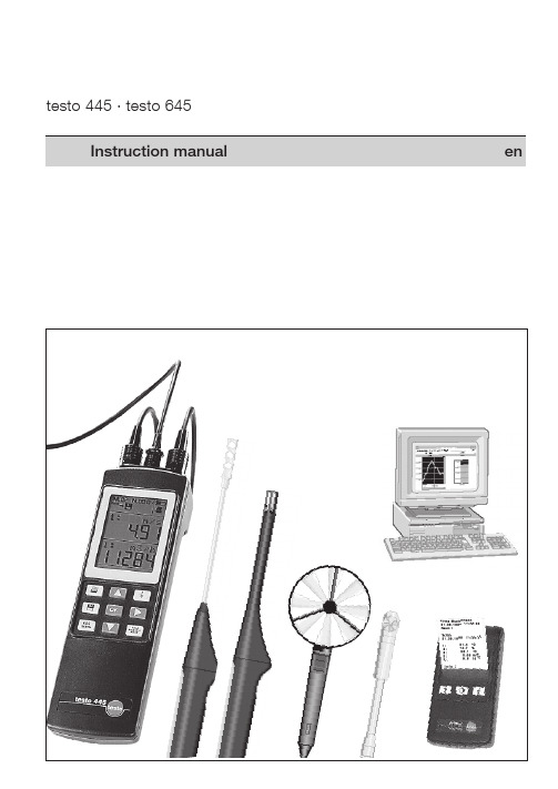
testo 445 · testo 645 操作手册说明书
testo 445 · testo 645Clearing memory contents ....................................................................................................1999 Copyright Testo GmbH & Co.The software and software structure included in the productForeword Dear CustomerYou have made the right decision by choosing a measuring instrument from Testo. Every year, thousands of customers purchase our high-quality products. There are many good reasons for this.1) We offer value for money. Reliable quality at the right price.2) Considerably longer guarantee periods of up to 3 years - depending on the instrument.3) With over 40 years of specialist experience we are optimally equipped to solve your measuringtasks.4) Our high quality standards are confirmed by ISO 9001 certification.5) It goes without saying that our instruments bear the CE mark required by the EU.Do not measure on live parts.Do not switch instrument on or off with the button- during instrument configurationRefer to “Power supply” Chapter for more information onalternative power supply, charge, battery quality, chargingprocedure.Observe instrument configuration when usingrechargeable batteries.controls guarantee a quick introduction.Note: The measuring instrument must be switched off before a probe is connected.You will receive up-to-date readings once a probe is inserted and the measuring instrument is switched on. However, you will still need to update or define the data in the instrument: Date/Time: Auto Off: Units:Some things can only be set via PC software (See Ordering data): Location name (8 characters) Log head (24 characters), e.g. your company name - is also printed when readings are printed.testo 44512V2RS2321Manual saving of a single measurement by pressing the save button .Automatic saving program has been set up. Saving is activated by pressing the button.Symbol for reading contents of memory on display. The symbol flashes while data is being transmitted. You can print on the desktop printer by pressing the print button .If the inner segment no longer appears (symbol flashes), thebattery has to be changed or the rechargeable battery has to be recharged. The instrument switches itself off automatically after M. 00N. 0000Save manually or automatically, are activated in accordance with the readingMulti-point mean calculation Update values Calculate mean Reset mean EANTimed mean calculation Start and end Calculate mean Reset meanESCLocationManual saving Print readingsButtons to select99°C °Fm/s fpm [ft/min] (testo 445)Factory resetPrint parametershPa mbar psiin W [”H O] (testo 445)°C, %, Abs.mbar,rho-g/m 3, Pitot tube factorm 3/h m /min m /sl/s cfm [ft 3/min](testo 445)Flashing display is activated and is.Current readings - different, depending on probe(s) connected.It is possible to activate the following functions during mea-suring at the touch of a button.ave readings Manual or automatic saving is determined by the save setting (Chapter 5)Print readings.Scroll with button in line 1:m/s...) to be displayed.Scroll withbutton in line 2: VBAT8.51Location Duct 158.0621.801:1:M.05MANN.0017m/shPa58.061:m/sNote on printing:A distance 0f 0.5 m should not be exceeded in order to guarantee problem-free data transfer. Objects betweenSee multi-point/timed mean calculationMaximum readings Minimum readings measurement began58.0621.601HLD 1HLDM.05MANN.0017m/shPa 58.0621.801:1:M.05MANN.0017m/shPa 73.3734.801MAX 1MAX M.05MANN.0017m/shPa 56.6220.001MIN 1MINM.05MANN.0017m/shPa ESCLocationHold Max/MinMean25.2101:OK MEANM.05MANN.0017m/s•25.215MEAN M EAN NEWM.05MANN.0017m/s•Select parameter required. Update values.Calculate mean58.0621.801:1:M.05MANN.0017m/shPa Hold Max/Min MeanHold Max/Min Mean Hold Max/Min Meancalculation possibleESCLocation55.2000:151:GO MEAN M.05MANN.0017m/s1:END MEAN M.05MANN.0017m/s00:1055.2100:05MEAN MEAN NEW M.05MANN.0017m/sStart timed mean calculationFinish timed mean calculation.Continue timed mean calculation orcalculate mean.New meancalculation possibleor58.0621.801:1:M.05MANN.0017m/shPa 55.2100:001:STARTM.05MANN.0017m/sNote on saved or printed logs:1. The log of a multi-point calculation contains single value, max. value, min. value and mean value.2. The log of a timed mean calculation contains max. value, min. value and mean value.Special solution for volume flow selected:3. Any additional velocity values (m/s) are saved with the volume flow values in the memory.ESCLocation55.17/ Select location58.0621.801:1:M.05MANN.0017m/shPa 01Location Duct 150.0A cm50.0B cmESCLocationor :From now on all measured data which is saved or printed is linked to the selected location or product names.The cross-sectioncan only be called up if volume flow is activated (testo 445 Return to current measurementESCThe respective flashing position can be changed using thebuttons or confirmed by pressing .Current measurementCAL ReRESET CAL1:69.670.01:2:M.05MANN.0017°C°C 70.000.41:CAL OFFSETM.05MANN.0017°CCurrent measurementcan select from the following parameters:td°Cg/m 3 g/kg J/g td°C ...Dew point Absolute Degree Enthalpytemperature humidity of humidityDegree of humidity and enthalpy are pressure-dependentppmvol%ppm ...The respective selected parameter flashes.10.12:M.05MANN.0017%12.92:1:M.05MANN.0017%2:1:M.05MANN.0017ppmCAL %td°C g/mppm vol%11.1CAL11.3 %NO YEStd°CSwitch to YES/NO15246m/sZero adjustment of differential pressure probe (hPa) and return to current measurement.The respective flashing setting is confirmed with .Switch volume flow (m3/h) in the display on and off.OFF flashes ON blinkt22.731:2:M.05MANN.0017mbarm/std°C hpa =0m/sONOFFm/s ONOFFm3/h Once the cross-section is entered, return to the current volume flow measurement./ =scroll value= Next positionA B ØAxB100. cm100. cm100, cm= round duct cross-section;...4 memory settings are possible. Select the required saving optionby pressing:MAN AUTO OUT CLEAR MAN ...The symbol corresponding to the selection appears in the top line.The function is activated with.AUTOMEMORYMANMAN AUTO AUTO OUT CLEAR MA MEMORYOUT CLEAR MEMORYMEMORYESCLocationESCLocationᕡᕢᕣᕤ58.0621.801:1:M.05MANN.0017m/shPa Press the button to get to the memory settings mode Confirm flashing save symbol via button.1966521.851:1:M.05MANN.0017m3/hm/s 1:M.05N.0017m3/hAUTOAUTOManual saving:Each timeis pressed a log of the measurement is saved in the instrument and includes measured values, location, date and time. The counter in the top left corner of the display shows the AUTO OUT MORY660AUTOCYCLE-N.0001:30AUTOCYCLE hmin sec ᕢM.06N.0001AUTOCancel saving procedure.Starts automatic saving again. An additional measurement series is added.MEMORYMANMAN AUTOof measuring cycles. Set required number using / / .Confirm set value by pressing .Select interval in which the measured values are to be saved. The blinking position can be changed using .Confirm set value by pressing .Automatic saving is started by pressing . The symbol flashesESCLocation1. Reading out or printing memory contents:If the “OUT” display is flashing and the button is pressed, contents is started. Cancel printout by pressing the 2. Selecting the location:Ifis activated selection options appear in the display to select the required location. Select location by pressing .If printing is activated by pressingat this (measurement series and cycles) for this location are printed.Cancel printout by pressing the button.Confirm the location selected above by pressing .The M.0x counter flashes in the display.Select the log no. by pressing .activates a printout of the selected measurement log.Pressto display the values measured.Cancel printout by pressing theConfirm the measurement log selected above by pressing .Select the measurement cycle by pressing .activates a printout of the selected measurement cycle.01:131998M.05N.0017Pizza01.0179.7°CM.05N.00171:79.7°CM.05N.00171:OUT CLEAR MEMORY01Location Duct 1Press the button to access the memory settings mode. Confirm flashing save symbol via the but-ton. Cancel printing by pressing the button.ESCLocationESCLocationESCLocationESCLocationESCLocationM essrs. Smith 31.08.199811:26:05Raum 1M .00131.08.1998 11:20:051: 21.4 2: 44.7 2: 22.1 2: 0.55 m/s 2: 9.6 td°CInfo :CLEAR Clearing memory:CLEAR MA MEMORYYES NO CLEARNO YES CLEARMemory isnot cleared Current measurementᕤMEMORYMANMAN AUTO Printout of manual saving:Press thebutton to access the memory settings mode. Confirm flashing save symbol via the button.Printout of automatic saving procedure:ustermann 31.08.1998 11:27:3231.08.1998 11:26:5900:00022:% 2:°C21.4 45.1 22.2 21.2 44.7 22.3 21.1 44.6 22.3 21.8 44.6 22.32:m/s2:td°C 01 1.00 9.81.66 9.72.01 9.71.52 9.758.0621.801:1:M.05MANN.0017m/shPa HeaderDate of prinoutLocationStart of savingReadingsSaveThebutton has to be kept pressed for approx. 2 seconds when switching on the instrument (button).The blinking position can be changed by pressingor confirmed by pressing . Power save functionAuto OFF function is switched on (“ON”)AUTO-OFF OFF ONAUTO-OFF ON OFF: B a t t e r y o r a c c uBAT ACCUACCU BATImportant: The instrument must be set at battery or rechargeable battery operation.Incorrect instrument settingIf a rechargeable battery is inside confirm Charge “Yes” with displayed. Recharging takes approximately 6 hours if the rechargeableOperationvia mainsunit (Partno. 0554.0088):Insert mains unit in the mains unit socket of the instrument (see connection assignment).ᕢThe flashing position in the display can be set-/= scroll/ = next position -The blinking position in the display can be set-/ = scroll/ = next position -Setting dateSetting the time01.011998DATE11:25TIME025.0Parameter°C2are pressure-dependent parameters./ = Scroll/ = Next position -= Confirm.= Print parameter.TemperatureHumidity3ParameterFactor1. Temperature2. Humidity3. Absolute pressure5. Pitot tube factor4. Density(calculated)°C °FThe selected parameter flashes.m/sfpm (ft/min) The selected parameter flashes.m3/hm3/m (m3/min) m3/s l/s cfm (ft3/min) testo 445 only)The selected parameter flashes.hPambar psi in W (The selected parameter flashesinstrument configuration to the factory settings.confirms the selection and switches to the display of the cur-rent setting.°Cmm3UnithPambar 20.051.82:2:M.05MANN.0017°C%RH Current measurementFactory resetventilation opening (grid or outlet with dual wall clearance). The opening of the funnel must be covered completely by the grid (max. 190 x 190 mm with 0554.0400 or max. 350 x 350 mm with 0554.0410).For the measurement, a velocity probe (0635.1041, 0628.0005or 0635. 9540) is placed in the funnel’s hole, is positioned in the middle and is aligned. The probe is snapped into the funnel’s handle. Connect the probe to the instrument and switch on.Position the cursor on the m/s parameter (or ).You will get to the “Parameter setting” menu by pressing . Press to get the volume flow (m 3/h) in the display. Confirm the m3/h ON setting by pressing .Press twice and confirm with .(funnel/=funnel factor).Enter the factor for the funnel used by you:Funnel factor for funnel with part no. 0554.0400 = 20Funnel factor for funnel with part no. 0554.0410 = 22Press the funnel tightly on the opening. You can accept the displayed reading as it is or you can carry out a timed mean calculation if the readings fluctuate.Press to activate the conversion. The “Parameter setting” menu is displayed. when activatedthe button. Confirm the m/s ON setting with .The next step is to decide, using the button, as to whether the volume flow is to be calculated immediately (m3/h ON) or not /h OFF). Confirm input with .Pitot tube factor S and the temperature, humidity and absoluteThermal anemometer probes (testo 445) The measuring principle of thermal anemometers with a heated wire or heated ball sensor is based on the cooling down of the sensor element via the air flow. The sensor element is heated to 100 °C for this purpose. The power needed to keep the sensor constantly at this temperature is a measure of the strength of the flow. According to this measuring principle, this probe requires a heating up period after being switched on which appears as ”Count Down” in the display. Measuring in accordance with this measuring principle depends on the ambient pressure. The absolute pressure can be set in the instrument configuration menu.The connected probe 0632.1247 is initialised during the switch-on phase (“Count Down” runs in the display). For this reason, the measuring instrument should only be switched on in an atmosphere free of CO. Values will be too low otherwise in subsequent measurements.If you want to initialize the instrument while switched on, place the probe in an atmosphere free of CO. Press and confirm initialisation of the CO probe (CO=0) by pressing again.Switch on - Initialisation phase (60 s).The ambient CO probe is initialised during the initialisation phase. • Remove yellow protective cap.• Probe can be put in shirt pocket, for example. The directionof the flow on the probe influences the accuracy of the measurement. Optimum measured results are achieved by moving the probe gently back and forth. If the air blows head-on on the sensor, the values measured will be too high.The 0632.1240 probe measures concentrations from0 to 1 vol % CO2. The unit can be switched between ppm and vol% as described in “Parameter settings” on page 16.The measuring principle is based on infrared absorption. The probe has a relatively high power consumption on account of its sensor. Use mains unit and rechargeable batteries for long-term measurements.Note: T he correct reading is available 20 to 30 seconds after being switched on.The corresponding “Count Down” is displayed.If there are major changes in the concentration, the probe needs 30 - 60 seconds to adapt itself to the outside world.Gently swinging of the probe shortens the adaptation time.Pressure offsetPlease note that the CO2 reading depends on absolute air pres-sure. This effect is compensated in the instrument.Enter the correct absolute pressure for the location in the “Instrument configuration” menu (see Chapter 6). Permissible ambient temperature: 0 to +50 °C Permissible storage temperature: -20 to +70 °CAbsolute pressure is calculated from:• E levation pressure (metres above NN)The annual mean is 1013 mbar at sea level, the higher the location above sea level, the lower the pressure.• B arometric pressureThe annual mean is 1013 mbar regardless of height. This pressure can deviate from the annual mean by ±20 mbar depending on the weather (see display on nearest barometer).• D ifferential pressureis the positive or negative pressure in the duct.You can determine the annual mean air pressure value for your elevation using the following table and any additional fluctuation using a barometer or ask your weather station for the exact air pressure value.Elevation M.S.LElevationM.S.LAir pressure(mbar)Air pressure(mbar)Air pressure(mbar)Air pressure(mbar)ElevationM.S.LElevationM.S.LExample:If you are at 800 m above mean sea level, you have an annual mean air pressure of 920 mbar.The annual mean air pressure has to be reduced by 10 (910 mbar air pressure) to correspond to the barometer display(1003 mbar) and to the barometer’s height offset (to 1013 hPa). Add the difference between your ambient air pressure and the static process air pressure (e.g. positive pressure in an air duct which is to be measured - can be measured using the differential pressure probe at up to 100 mbar) to this (air) pressure value. Example: We have measured an annual mean air pressure of 910 mbar. We will now add 90 mbar based on the static process pressure. We therefore assume an absolute air pressure in the measurement medium of 1000 mbar.The table on page 31 is also saved in the Testo Comfort software. Absolute pressure can be calculated automatically using this software if the height above mean sea level, barometric pressure and differential pressure are entered. The calculated absolute pressure is then taken over by the instrument.* With EEPROM: Precision adjustment for each probe at a measuring point* Accuracy data at rated temperature of +25 °C, temperature coefficient ± 0.03% / °C。
罗托光 SmartSoft 盒子安装指南说明书
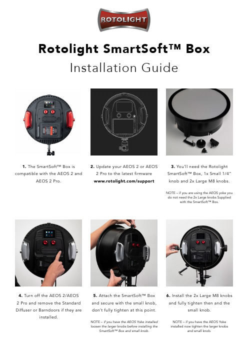
Rotolight SmartSoft™ BoxInstallation Guide1. The SmartSoft™ Box is compatible with the AEOS 2 andAEOS 2 Pro.2. Update your AEOS 2 or AEOS 2 Pro to the latest firmware/support4. Turn off the AEOS 2/AEOS 2 Pro and remove the Standard Diffuser or Barndoors if they areinstalled.5. Attach the SmartSoft™ Box and secure with the small knob, don’t fully tighten at this point.NOTE – if you have the AEOS Yoke installed loosen the larger knobs before installing theSmartSoft™ Box and small knob.6. Install the 2x Large M8 knobs and fully tighten then and thesmall knob.NOTE – if you have the AEOS Yoke installed now tighten the larger knobsand small knob.3. You’ll need the Rotolight SmartSoft™ Box, 1x Small 1/4” knob and 2x Large M8 knobs.NOTE – if you are using the AEOS yoke you do not need the 2x Large knobs Suppliedwith the SmartSoft™ Box.7. Connect the SmartSoft™ Box control cable to the AEOS 2 /AEOS 2 Pro.8. Turn ON the AEOS 2 / AEOS2 Pro.9. In CCT press the bottom lefticon twice to cycle between thebrightness and SmartSoft™ control.10. Used the on-screen slider orleft Red Control dial increase anddecrease the amount of diffusion.You are now ready to shoot!1. To Remove the SmartSoft™Box turn OFF the AEOS 2 /AEOS 2 Pro.2. Disconnect the Control cablefrom the AEOS 2 / AEOS 2 Pro.3. Loosen the 2x Larger knobs4. Remove the small 1/4” knoband then the SmartSoft™ Box5. Now you are ready to attach ourother light Modifiershttps:///product-category/light-modifiers/How to uninstall SmartSoft™ Box。
- 1、下载文档前请自行甄别文档内容的完整性,平台不提供额外的编辑、内容补充、找答案等附加服务。
- 2、"仅部分预览"的文档,不可在线预览部分如存在完整性等问题,可反馈申请退款(可完整预览的文档不适用该条件!)。
- 3、如文档侵犯您的权益,请联系客服反馈,我们会尽快为您处理(人工客服工作时间:9:00-18:30)。
常规技术参数
兼容性
储存温度 操作温度 电池类型 电池寿命 尺寸
应用: • 测量环境室外、室内的空气温湿度 • 测量通风管道内或进出风口的温湿度 • 可自动计算并显示大气露点及湿球温度值 产品优势: • 通过smart probe APP,可实现多点同时检测或同时获得多参数的测量值 • 通过APP,可记录/图表曲线显示时间段的温湿度变化,了解系统状态 • 相关测量数据均可记录保存或生成测量报告
testo 805i各1台, 便携式仪器箱
无线迷你制冷系统检测套装 套装含:testo 549i,testo 115i各2台,
便携式仪器箱
通风系统检测套装可协助您全面检测空调 通风系统的温湿度,风速,风量等参数, 并可生成专业的检测报告。
供暖系统检测套装可协助检测人员测量系统 的管道温度及压力状态,对供暖系统进行初 步评估检测,是检测人员的得力工具套装。
应用: • 供暖系统的出水及回水管道温度测量 • 制冷系统的出水及回水管道温度测量 • 通风系统的进风及出风管道温度测量
产品优势: • 通过smart probe APP,可实现多点同时检测 • 通过APP,与其它无线探头配合,可直接获得相关参数计算值(如
制冷系统过冷,过热值) • 通过APP,可记录/图表曲线显示时间段的温度变化,了解系统状态 • 相关测量数据均可记录保存或生成测量报告
叶轮式风速测量仪
压力测量仪
testo 805i 无线迷你 红外测温仪
*具体产品详情请咨询德图
推荐测量套装
无线迷你通风系统检测套装 套装含:testo 405i,testo 410i,
testo 605i,testo 805i 各1台, 便携式仪器箱
无线迷你供暖系统检测套装 套装含:testo 115i,testo 510i,
常规技术数据
兼容性
存储温度 操作温度 电池类型 电池寿命 尺寸
NTC
-40 ~ +150 °C ±1.3 °C (-20 ~ +85 °C) 0.1 °C
需要iOS 8.3或更高版本 / Android 4.3或更高版本 需要配备Bluetooth 4.0的移动终端设备 -20 ~ +60 °C -20 ~ +50 °C 3节AAA 250h 183 x 90 x 30 mm
需要iOS 8.3或更高版本 / Android 4.3或更高版本 需要配备Bluetooth 4.0的移动终端设备
-20 ~ +60 °C -10 ~ +50 °C 3节AAA 30h 10:1 激光圈 140 x 36 x 25 mm 0.1~1.0可调
订货号 0520 0002
6
湿度测量
testo 605i 无线迷你温湿度测量仪
技术数据/附件
testo 115i
testo 115i 无线迷你管钳式温度测量仪,NTC温度传 感器,保障测量精度,带有电池和出厂检测报告。
传感器类型
测量范围 精度 ±1数位 分辨率
订货号 0560 1115
德图 Smart Probe APP • 使用方便:可用于IOS和Android系统,任意APP
制冷系统检测套装适用于空调制冷系统的 维护及故障检测,以及系统的安装运行调 试,是检测人员的得力工具套装。
• 多个探头(参数)可同时测量,可即时 读取并保存测量数据
• 可列出若干风口或管道不同部位风量值, 并可计算显示总流量值(在报告内)
• testo 605i和testo 805i结合使用,可发 现建筑墙体霉变陷患
附件
ISO温度校准证书,用于钳式温度计的单点校准,校准点+60 °C
订货号 0520 0072
4
温度测量
testo 905i 无线迷你空气温度测量仪
专业的空气温度测量设备 应用: • 可测量环境室内、室外空气温度 • 可测量通风管道内或进出风口的空气温度 产品优势: • 通过smart probe APP,可实现多点同时检测 • 通过APP,与其它无线探头配合,同时获得多参数的测量值 • 通过APP,可记录/图表曲线显示时间段的温度变化,了解系统状态 • 相关测量数据均可记录保存或生成测量报告
Bluetooth + App 温湿度、风速、压力 还有更多……
开启智能测量新时代 无线版环境测量系列产品全新上市
德国测量专家 品质始终如一
1
德图智能测量探头:让您的手机秒变成专业检测仪器
德图全新推出的智能测量移动产品涵盖温度、温湿度、风速、压力等重要参数的测量。其创新之处在于此系列产品通过蓝牙传输方式 将您的手机秒变成一台专业的检测及分析仪器。通过专业的APP可读取、记录、分析单个或多个测量数据,并可直接制成报告并发送。
表面温度值 • 通过Smart probe APP的压降功能可设
定报警限值,了解系统压降状态 • 通过Smart probe APP,可实时显示,
记录,分析,发送数据及报告
• 制冷系统检测套装可提供直接测量的进 出口水温,高低压值的状态
• 通过Smart probe APP,可自动计算制冷 系统的蒸发(冷凝)温度,过冷(过热) 值,全面了解系统运行状况
技术数据/附件
testo 805i
testo 805i 无线迷你红外测温仪,带有电池和出 厂检测报告。
订货号 0560 1805
德图 Smart Probe APP • 使用方便:可用于IOS和Android系统,任意APP
商店即可免费下载使用。 • 数据集成管理:将您的手机直接秒变为专业测量设
备,可同时测量多外测量点,可显示,记录,分析 连接探头的全部测量数据。 • 专业的分析及报告:除直接测量参数外,APP还可 提供相关参数的综合计算值,如制冷系统的蒸发冷 凝温度,过冷过热值,可直接使用程序创建测量报 告,并通过电子邮件发送。
备,可同时测量多外测量点,可显示,记录,分析 连接探头的全部测量数据。 • 专业的分析及报告:除直接测量参数外,APP还可 提供相关参数的综合计算值,如制冷系统的蒸发冷 凝温度,过冷过热值,可直接使用程序创建测量报 告,并通过电子邮件发送。
传感器类型 (湿度)
量程 精度 ±1数位 分辨率
电容式
0~100 %RH ±(1.8 %RH+ 3 %测量值), 在 +25 °C时, (5~80 %RH) 0.1% RH
电气测试
testo 115i 无线迷你管 testo 605i 无线迷你 testo 405i 无线迷你 testo 510i 无线迷你 *testo 770-3 真风速测量仪
差压测量仪
值交直流电钳形表
testo 905i 无线迷你 空气温度测量仪
testo 410i 无线迷你 testo 549i 无线迷你
5
温度测量
testo 805i 无线迷你红外测温仪
专业的非接触式表面温度测量设备 应用: • 非接触式测量物体的表面温度 • 采用8点环状激光瞄准器标记测量点,清晰定位 产品优势: • 通过smart probe APP,根据存储的材料清单选择发射率 • 通过smart probe APP 及手机相机,获取被测物体的即时图片 • 通过smart probe APP,可实现多点同时检测或同时获得多参数的测量值 • 通过APP,可记录/图表曲线显示时间段的温度变化,了解系统状态 • 相关测量数据均可记录保存或生成测量报告
商店即可免费下载使用。 • 数据集成管理:将您的手机直接秒变为专业测量设
备,可同时测量多外测量点,可显示,记录,分析 连接探头的全部测量数据。 • 专业的分析及报告:除直接测量参数外,APP还可 提供相关参数的综合计算值,如制冷系统的蒸发冷 凝温度,过冷过热值,可直接使用程序创建测量报 告,并通过电子邮件发送。
• testo 549i 直接连接压力管道,最小可 能减少制冷剂损耗
• 通过Smart probe APP,可实时显示, 记录,分析,发送数据及报告
订货号 0563 0003
订货号 0563 0004
订货号 0563 0002
3
温度测量
testo 115i 无线迷你管钳式温度测量仪
专业的管道温度测量设备,可用于测量φ6~35mm的管道温度
Bluetooth + App testo 605i
Bluetooth
+ App
testo 115i
A
V
1
℃
bar
Bluetooth + App testo 770-3
Bluetooth + App testo 549i
Bluetooth + App testo 905i
2
产品概览
温度
湿度
风速
压力
附件
ISO校准证书(温度),用于空气/浸入式探头,校准点–18 °C; 0 °C, +60 °C ISO 温度校准证书,用于空气/浸入式探头,校准点-18 °C ISO温度校准证书,用于空气/浸入式探头,校准点0 °C ISO温度校准证书,用于空气/浸入式探头,校准点+60 °C
订货号 0520 0001 0520 0061 0520 0062 0520 0063
仪器小巧、测量灵活、数据真实、高效工作
m/s
℃ m/s
℃
Bluetooth + App testo 405i
℃
Bluetooth + App testo 410i
hPa m/s
Bluetooth + App testo 510i
