IF-9401-S单防区输入输出扩展模块安装说明书
FVG9401中文
调节装置FVG9401服务与操作说明软件版本V6.25 Doc.-No.:SH02.10 S1.00 - 05E06出版:2008年11月7日Beutwang 4电话+ 49(0)70 22-95 65-0尼尔廷根D - 72622传真:+ 49(0)70 22-95 65-501网址:www.sh - el.de电子邮箱:info@sh-el.de目录1设备版本..................................................................................................................................................................... . (6)2排版约定....................................................................................................................................................................... . .7 3介绍............................................................................................................................................................................... (9)4安装 (10)4.1一般资料 (10)4.2安全信息 (10)4.3安装位置 (11)5快速启动 (12)5.1需求 (12)5.2手动控制 (13)5.3调节范围的设置 (13)6开始运作 (15)6.1条件 (15)6.2主菜单 (16)6.3手动控制 (17)6.3.1液晶区域 (19)6.3.2状态代码显示(LED) (20)7数据文件和操作模式............................................................................................................................................ .. (21)7.1概述 (21)7.2选择文件 (21)7.3复制文件 (22)8油门操作 (23)8.1概述 (23)8.2全新设置 (23)8.3手动控制 (24)8.4正确的设置数据 (24)8.4.1手动设置零和结束位置 (25)8.4.2自动设置零和结束位置 (26)8.4.3正确的移动速度 (27)8.4.4正确的移动力 (27)8.4.5超载时切断 (27)8.4.6类型识别的变化 (28)8.5微型终端MT1操作 (29)8.5.1 MT1的连接和概述 (29)8.5.2 MT1的主菜单 (29)8.5.3 MT1 -设置 (30)8.5.4 MT1的数据文件选择 (30)8.5.5 MT1 -设置- 语言 (31)8.5.6 MT1 -设置- 电机 (31)8.5.7 MT1 -设置–概述 (32)8.5.8 MT1安装程序–概述2 (33)8.5.9 MT1的手动控制 (33)8.5.10 MT1 -手动控制(菜单2) (34)8.5.11 MT1 -校正菜单 (35)8.5.12 MT1 -自动设定 (35)8.6.3控制器释放时移动速度 (40)8.6.4零和结束位置力的设置 (41)8.6.5自动设置移动速度 (41)8.6.6零和结束位置切换 (42)8.7出厂设置 (43)8.7.1位置窗口 (44)8.7.2模拟输出标定--实际位移 (44)8.7.3模拟输出标定--实际力 (45)8.7.4模拟设置标定-点力 (45)9 E - GAS操作 (46)9.1概述 (46)9.2全新设置 (46)9.3手动控制 (47)9.4正确的设置数据 (48)9.4.1手动设置零和结束位置 (48)9.4.2自动设置零和结束位置 (49)9.4.3正确的角速度 (50)9.4.4正确的移动力矩 (50)9.4.5过载时的切断 (51)9.4.6类型识别的变化 (51)9.5微型终端MT1的操作 (52)9.5.1 MT1的连接和概述 (52)9.5.2 MT1的主菜单 (52)9.5.3 MT1 -设置 (53)9.5.4 MT1 -数据文件选择 (54)9.5.5 MT1 -设置- 语言 (54)9.5.6 MT1 -设置- 电机 (55)9.5.7 MT1 -设置- 概述 (56)9.5.8 MT1安装程序- 概述2 (56)9.5.9 MT1手动控制 (57)9.5.10 MT1手动控制(菜单2) (58)9.5.11 MT1校正菜单 (58)9.5.12 MT1自动设定 (59)9.5.13MT1 -手动设置 (59)9.5.14MT1转矩和角速度的改变 (60)9.5.15MT1零和结束位置力的设置 (61)9.5.16 MT1过载是切断 (61)9.6基本设置 (62)9.6.1实际位移的输出 (62)9.6.2自动设置时的缓冲距离 (63)9.6.3控制器释放时的角速度 (63)9.6.4零位和结束位置力矩时设置 (64)9.6.5自动设置时的角速度 (64)10.1概述 (69)10.2全新设置 (69)10.3手动控制 (70)10.4正确的设置数据 (71)10.4.1正确的转移步骤 (72)10.4.2首选位置的变化 (73)10.4.3正确的移动速度 (74)10.4.4正确的移动力............................................................................................................................................... (74)10.4.5过载时关闭 (75)10.4.6类型识别的变化 (75)10.5操作微型终端MT1 (76)10.5.1 MT1的连接和概述 (76)10.5.2 MT1的主菜单... (76)10.5.3 MT1的设置... . (77)10.5.4 MT1数据文件的选择 (78)10.5.5 MT1 -设置- 语言...... (78)10.5.6 MT1 -设置–电机 (79)10.5.7 MT1 -设置–概述 (80)10.5.8 MT1的手动控制 (80)10.5.9 MT1的校正菜单 (81)10.5.10 MT1 -更改转移步骤 (82)10.5.11 MT1 -更改移力和速度 (82)10.5.12 MT1 -设置力 (83)10.5.13在超载MT1停机 (84)10.6基本设置...................... .. (85)10.6.1换档速度控制器推出. (85)10.6.2设置队......................... (86)10.6.3流产模式 (86)10.6.4时间淘汰目标位置达到 (87)10.7厂设置 (88)10.7.1位置窗口..................... (89)10.7.2缩放的模拟输出实际的旅行 (89)10.7.3缩放的模拟输出的实际受力 (90)10.7.4缩放模拟量设定点力............. (90)11模拟量控制系统 (91)11.1总则 (91)11.2模拟输入 (91)11.3模拟输出 (91)12个数字控制系统 (92)12.1概述 (92)12.2二进制输入 (92)12.2.1选择数据文件通过二进制输入 (93)12.2.2选择通过二进制输入转移步骤 (93)13.2.1概述.................................... .. (100)13.2.2基本设置........................... .. (100)13.2.3数据外汇........................... .. (101)13.2.4过程数据接口(PZD ) .... .. (102)13.2.5参数接口(PKW ) (104)14个一般的基本设置................ .. (106)14.1概述 (106)14.1.1波特率率 (107)14.1.2通过RS232自动错误信息 (107)14.1.3输入代码号 (108)14.1.4安全等级 (108)14.1.5声音报警 (109)14.1.6视角液晶 (110)14.1.7兼容模式COM1 .............. .. (111)14.1.8风扇 (111)14.2现场总线 (112)14.2.1接口(选件)...................... .. (113)14.3诊断菜单............................... .. (114)14.4碰撞....................................... .. (116)15总厂设置................................. .. (117)15.1概述 (118)15.1.1语言 (118)15.1.2内存擦除 (119)15.1.3数据初始化 (119)15.1.4测定电机和编码器数据 (121)15.1.5 AD / DA调整 (122)15.1.6控制器系数 (125)15.1.7软件版本 (125)15.1.8弹簧参数 (125)15.2激活选项 (127)16测试菜单 (128)16.1输入 (129)16.1.1模拟输入,第1部分 (129)16.1.2模拟输入,第2部分 (130)16.1.3二进制输入 (131)16.2输出 (132)16.2.1模拟输出 (132)16.2.2二进制输出 (133)16.3信号测试 (134)16.3.1信号测试SACT (134)16.3.2信号测试概况 (135)16.4串行接口 (136)16.5电机测试 (137)17.1错误代码 (141)17.2模块 (144)18机械调整(标准版) (145)18.1连接 (145)18.1.1钢挺杆 (145)18.1.2 FLEXBALL耦合 (145)18.1.3 FLEXBALL安排 (146)18.1.4踏板设定点调节器 (146)18.1.4.1安装踏板设定点调节器(博世) (146)18.2最终停止.............................................. . (147)18.3复位设备 (147)18.3.1方向的影响 (148)18.3.2操作无需重新调节弹簧 (148)18.4旋转电机............................................. .. (148)19机械调整(EC -版)............................. .. (149)19.1连接........................ . (149)20机械调整(踏板设定点调节器版) (150)20.1概述................................................ . (150)20.2最终停止 (150)21保养和维修说明 (151)21.1滚珠螺杆(标准版) (151)21.2执行器EC -版本 (152)21.3除尘过滤器 (152)21.4 NEXTEL涂层 (152)22附录................................................ ... . (153)22.1设备连接....................................... . (153)22.1.1电源连接X1的 (153)22.1.2电机连接X2和X10的 (153)22.1.3编码器连接X3和X11的 (154)22.1.4 Miniterminal连接X12 ................... .. (154)22.1.5信号的连接 (154)22.1.6 PC的控制和外部的控制面板 (155)22.2设备保险丝 (155)22.3技术资料 (156)22.3.1控制响应............................. . (159)22.4 EC合格声明.......................... . (160)22.5基本数据初始化数据............ . (161)22.5.1标准版 (161)22.5.2 EC -版本.............................. . (162)22.5.3一般的基本设置................. . (163)22.6输入区..................................... . (163)22.6.1油门和换档杆操作.............. . (163)22.6.2电子气体操作 (163)22.7二维草图 (164)22.11版本,状态码显示前视图 (173)22.12查看Miniterminal MT1 (174)23流行语指数.................................................................................................... .. (175)第一章设备版本控制机架标准版本正视图请参阅第172页状态代码显示的版本正视图请参阅第173页二维草图请见第164页执行机构标准版本二维草图请见第165页踏板设定点调节器的版本二维草图请见第165页FLEXBALL或螺栓耦的EC -版本二维草图请见第166页商标参考此产品在本手册或其他文件中提到的所有产品和品牌名称可能是商标或注册商标的具有特殊法律效率的东主。
北京迈特安技术 报警主机联动扩展模块 说明书

报警主机联动扩展模块使用手册23DR+北京迈特安技术发展有限公司感谢您选用北京迈特安技术发展有限公司的23DR+报警主机联动扩展模块,希望我们先进的防盗报警系统会给您的生活、工作带来安全与方便!文件名称:报警主机联动扩展模块 23DR+ 使用手册文件版本:ver 1.0公司名称:北京迈特安技术发展有限公司目录目录 (1)1. 产品概述 (1)2. 接口描述 (1)2.1. 电路接口 (1)2.2. 主机接线 (2)2.3. 继电器接线 (2)2.4. 电平输出(LED) (2)3. 功能设定 (3)3.1. LED输出设置 (3)3.2. 扩展联动设置 (3)3.3. 报警延时设置 (4)3.4. 注意事项 (4)4. 测试模式 (4)5. 状态提示 (5)6. 电气参数 (5)1.产品概述23DR+是针对Honeywell 23系列主机设计的显示驱动及继电器联动模块。
模块通过报警主机键盘获取防区报警状态,提供多达16路的LED 显示、电平驱动及继电器控制,可以方便的组成报警联动监控系统或电子地图板,可为主机每个报警防区提供一个输出端口。
23DR+的继电器为弱电继电器,可以联动DC28V以下电压的电气设备,电平输出接口通常用于联动LED指示灯。
2.接口描述2.1. 电路接口出厂默认设置:继电器常开/常闭设置:常开NO电平输出设置:常亮状态(L端)扩展联动方式设置:1端,传统联动方式报警延时方式设置:2端,传统联动方式2.2. 主机接线z DC+12:直流12V电源正极;z GND:直流12V电源地线;z KEY-:主机C端;z DATA:主机DATA端。
2.3. 继电器接线通过设定继电器后面对应的跳线,可以独立定义每个继电器的常闭/常开状态。
在两排继电器的左右两侧分别定义了NC/NO端,用户可以根据应用需要,自行进行设置。
2.4. 电平输出(LED)z 将LED 的阴极连接到JLED1和JLED2中相应的防区端子中; 助电源输出,每个LED 指示灯应串联一个Ω通端子,可以选择LED 触发时电平输出3. 功能设定23DR+设计了三组跳线,用于设定联动模块的工作方式,依次为LED 输出z LED 指示灯组为共阳极接法,阳极公共端连接到JLED1或JLED2的AUX 端中;z AUX 端提供+5V 辅510~1K Ω的限流电阻;z 过LED 输出闪烁设置为常亮状态(L 端),或1秒周期闪烁状态(F 端)。
单防区单输出总线通信模块 AW-BIX01 安装说明
AW-BIX01是连接在AW-BM1600大型总线报警主机扩充总线上使用的总线通信扩充模块,提供1个标准接线防区输入和一路集电极开路输出,输出端口可通过编程设定自身联动输出(即对应本身的输入防区实现报警联动)和外部控制输出两种工作模式,外部控制支持手动命令控制输出和可编程的报警联动输出控制模式。
其很小的体积足以直接放置在某些体积较大的探测器中,因此AW-BIX01更加适合在防区比较分散又需要一一对应进行现场联动的报警系统中使用。
另外,AW-BIX01使用和维护简单方便,只需通过拨码开关设置一个485地址接入总线系统中即可使用。
主要性能工作电源:直流10-28V,具备反极性保护工作电流:约20mA防区输入:1个带2K线末电阻标准接线防区防区类型:包括出入口、防拆、内部、周边、煤气、火警锁匙布撤防、24小时无声紧急、24小时有声紧急防区监控保护:2KΩ±30%线末监控电阻联动输出:单路集电极开路输出(驱动能力不大于200mA),实现一一对应现场联动通信接口:两线485总线通信接口通讯协议格式:MODBUS工业控制器网络通信协议485地址方式:六位拨码开关485地址范围:01~62LED通信状态指示体积小,可放置在某些探测器内无需编程,在主机中登记后即可使用工业级芯片,可适合户外使用支持防区旁路功能硬件看门狗功能防雷保护措施工作温度:-20ºC~50°C工作湿度:不大于90%,非凝露外形尺寸:60mm X 20mm警告:通电前一定要确保输出端不可裸露,否则容易导致输出短路而使内部电路永久损坏。
模块与管理主机接线规范请参照管理主机安装说明的相关章节。
附:485地址拨码表地址拨码 1 2 3 4 5 678910111213 14 15 1617181920211 On Off On off On Off On Off On Off On0ff0n 0ff 0n 0ff On Off On off On2 Off On On Off Off On On Off Off On On0ff0ff On 0n 0ff Off On On Off Off3 Off Off Off On On On On Off Off Off Off0n0n 0n 0n 0ff Off Off Off On On4 Off Off Off Off Off Off Off On On On On On0n 0n 0n 0ff Off Off Off Off Off5 Off 0ff Off Off Off Off Off Off Off Off Off0ff0ff 0ff 0ff 0n0n0n0n0n0n6 Off 0ff 0ff 0ff 0ff 0ff0ff0ff0ff0ff0ff0ff0ff 0ff 0ff 0ff Off0ff0ff0ff0ff 拨码22 23 24 26 26 2728293031323334 35 36 3738394041421 Off On Off On Off On0ff0n0ff0n0ff On Off On off On Off On Off On Off2 On On Off Off On On0ff0ff On0n0ff Off On On Off Off On On Off Off On3 On On Off Off Off Off0n0n0n0n0ff Off Off Off On On On On Off Off Off4 Off Off On On On On On0n0n0n0ff Off Off Off Off Off Off Off On On On5 0n 0n 0n 0n 0n 0n0n0n0n0n0ff Off0ff Off Off Off Off Off Off Off Off6 0ff 0ff 0ff 0ff 0ff 0ff0ff0ff0ff0ff0n On0n 0n 0n 0n0n0n0n0n0n 拨码43 44 45 46 47 4849505152535455 56 57 5859606162631 On 0ff 0n 0ff 0n 0ff On Off On off On Off On Off On Off On0ff0n0ff0n2 On 0ff 0ff On 0n 0ff Off On On Off Off On On Off Off On On0ff0ff On0n3 Off 0n 0n 0n 0n 0ff Off Off Off On On On On Off Off Off Off0n0n0n0n4 On On 0n 0n 0n 0ff Off Off Off Off Off Off Off On On On On On0n0n0n5 Off 0ff 0ff 0ff 0ff 0n On On On On On On On On On On On On On On On6 0n 0n 0n 0n 0n 0n On0n0n0n0n0n0n 0n 0n 0n0n0n0n0n0n。
XD扩展模块用户手册

TX3211输入/输出模块安装使用说明书
一、概述TX3211输入/输出模块(以下简称模块)符合国家标准GB16806-2006《消防联动控制系统》。
本模块用于控制具有动作信号输出的自锁型消防设备(如:排烟口、送风口、防火阀等),负责将火灾报警控制器的联动指令传送给受控设备,再将受控设备的动作反馈信号传送回火灾报警控制器。
本模块外形美观,采用插拔式结构,方便施工安装;采用专用集成芯片,具有强大的分析判断能力,可对所连接受控设备的控制线(断路状态、短路状态)、反馈线(断路状态、短路状态)进行检测,并通过指示灯给出状态指示。
注意:在输入线的末端(远离模块端)必须并联一个10KΩ的终端电阻,否则控制器将报该模块的“反馈线故障”。
由于输出线接有受控设备作为负载,故无须配接终端电阻;不可断开受控设备做试验,否则控制器将报该模块的“输出线故障”。
输出端口连续启动间隔时间大于180S。
若回路联动设备全部为此模块,最大带载数量为100个。
二、特点1.二总线,无极性2.采用专用集成芯片3.总线、输入线、输出线之间均采用隔离设计,减少外部干扰的影响4.输入可设置为常开或常闭模式5.输出为有源脉冲输出6.软硬件多级滤波,提高抗干扰能力7.插拔式结构,方便施工安装三、技术参数1.总线协议:T3协议2.工作电压:总线电压:15~28V(脉冲电压)3.工作电流:总线监视电流:≤0.5mA总线动作电流:≤2mA4.指示灯:输入指示灯:红色(正常监视状态闪亮一次,故障状态闪亮两次,反馈状态常亮)输出指示灯:红色(动作状态常亮)5.编码方式:电子编码(占一个总线地址点,编码范围在1~242之间任意设定)6.终端电阻:10KΩ7.输出容量:DC32V/1.5A/30ms8.线制:无极性二总线9.使用环境:温度:-10℃~55℃相对湿度:≤95%RH,不凝露10.外形尺寸:86mm×86mm×33mm(含底座)11.重量:约114g(含底座)12.执行标准:GB16806-2006四、结构特征和工作原理1.模块的外形尺寸及安装尺寸如图1所示(单位:mm)。
全球系统技术I-9401可寻址警报闪光灯C-9401警报闪光灯安装与使用手册说明书

I –9401 Addressable Sounder StrobeC-9401 Sounder Strobe Installation and Operation Manual(Issue 3.0, February 2004)Global System Technology PLCCONTENTSI General (1)II Features (1)III Technical Specifications (1)IV Structure and Operation Principle (2)V Mounting and Wiring (2)VI Testing (4)VII Applications (4)I GeneralSounder Strobe is a kind of optical and visual alarm device used to warn people in field when fire occurs.GST produces two types of sounder strobe, addressable (I-9401) and conventional (C-9401). Addressable sounder strobe can be started directly by fire alarm controller. It can be electronically programmed and modified by P-9910 Hand Held Programmer in field. Conventional sounder strobe can give optical and visual alarm when powered by DC24V, and can be connected to fire alarm controller through an addressable linkage control module. When it is not started, wire checking can be done by loading reverse voltage and connecting terminal resistor at the end of the circuit.II Features1. Red plexiglass panel, several strong red LED as light source, striking, long-life andlow consumption.2. Fire alarm sound over 85dB, easy to catch attention.3. Circuit part and base box are plugged together, reliable contact convenient forengineering;Addressable:4. Peripheral control terminals to startup the sounder strobe directly by passivenormally open contact (e.g. manual call point), unaffected by power-cut of signal bus.5. Signal bus and power bus non-polarized, easy for connection.6. Function of checking power-cut, sending fault information to the controller.7. Electronic programming of address code that can be modified on site. Conventional:8. DC24V two-wire, polarized, easy for wire checking (connecting terminal resistorwhen checking, the resistance value can be deiced by connecting devices).III Technical Specifications1. Operating Voltage (power bus terminal only for conventional):Signal Bus Voltage: 24V Range Allowed: 16V~28V;Power Bus Voltage: DC24V Range Allowed: DC20V~DC28V2. Operating Current (power alarming current only for conventional):Power Standby Current≤10mA;Power Alarming Current≤160mA;Loop Standby Current≤0.8mA;Loop Starting Current≤6.0mA.3. Flashing Frequency: 20~180 times every minute when alarming;4. Alarm Voice≥85dB(Due front 3m horizontal (A weighted))5. Wiring:Addressable: Four wires, non-polarized, two-loop to the controller,non-polarized two-wire to the power.Conventional: Non-polarized two-wire with the power.6. Operating Environment:Temperature: -10℃~+50℃;Relative Humidity≤95%, no condensation;7. Dimension: 144mm×90mm×57mm;8. Material and Color of Enclosure: ABS/ ivory white, front inlaid with plexiglass/red9. Hole Distance: 65mmcontrolled by timing circuit giving flashing light signal.Intelligent sounder is built in with microprocessor, which execute communication with fire alarm controller, checking power cut of the power bus and startup of audio and visual signals. Intelligent sounder strobe can start audio and visual signal after receiving startup command from fire alarm controller or directly by outer controlling contact.Conventional sounder strobe can be started when loading DC24V between D1 and D2.V Mounting and WiringWarning: Before installing the device, disconnect the power from the loop and verify that all bases are securely installed and that the wiring polarity is correct atconventional sounder strobe can be reset by power cut. Notify the proper authorities the system is back on line.5. If a sounder strobe fails in testing, check its connection and test again. If it still fails,return for repair.VII ApplicationsThe wiring of signal bus and power bus for intelligent sounder strobe and direct control through passive normally open contact of manual call point are shown in Fig.5:and D2 is negative which are reverse when not started up.。
上海有续自动化技术有限公司 D900 系列通讯扩展模块使用手册说明书

有续D900系列通讯扩展模块使用手册产品安全使用说明在开始使用之前请仔细阅读操作指示及注意事项,用以减少意外发生,负责安装和操作的人请严格遵循安全规范,说明中的安全问题并不代表所有,只代表各安全注意事项的补充。
错误操作可能致人员死亡、严重人身伤害等重大损失错误操作可能导致人身伤害或者财产损失错误操作可能导致产品损坏或者财产损失一、环境说明1环境潮湿,有环境潮湿,有凝露,有水滴,溅水等地!2.有腐蚀性气体、粉尘、可燃气体、油烟浑浊等地不可使用!3.有水、化学药品等导电液体飞溅到的地方二.配线说明1、避免接近高压、大电流的电源或电缆2、电源勿超压,短接电源擦出火花引起火灾3、通讯电缆连接无误,切勿把电源线插入通讯口4、避免接入过高电压,切勿剪线时勿将电线渣飞进模块端口【安全注意事项】有续系列的转换模块可应用在各种工业控制场合,建议按照技术人员的要求配线,以及使用,如若未按照遵守规定导致人员伤亡,财产损失,并且可能导致产品损坏,或故障损坏而无法使用;目录一、前言 (4)二、产品简介 (4)1、产品特点 (4)2、通讯参数简介 (4)3、产品规格说明 (5)三、产品接线图 (5)四、配置软件链接以及设备 (6)1、测试软件使用方法 (6)2、恢复出厂设置 (9)3、通讯参数表(MODBUS协议通讯参数写入值对照表) (10)五、附录 (13)1、MODBUS 03读取命令码详细解说 (13)2、MODBUS 10码写入命令码详细解说 (14)3、各品牌PLC地址映射MODBUS地址对照表 (14)一、前言欢迎选购本公司开发的转换模块,本公司专注于工业自动化控制,在工控领域耕耘十几年,具有丰富的工业设备开发经验,产品包括 PLC、触摸屏、行业专机控制器,配套有丰富扩展包括模块数字量输入输出模块、模拟量输入模块、模拟量输出模块、温度模块、GSM 模块、GPRS 模块、以太网模块、CAN 模块、Ethercat、转换模块等等。
消防模块接线方法和接线图
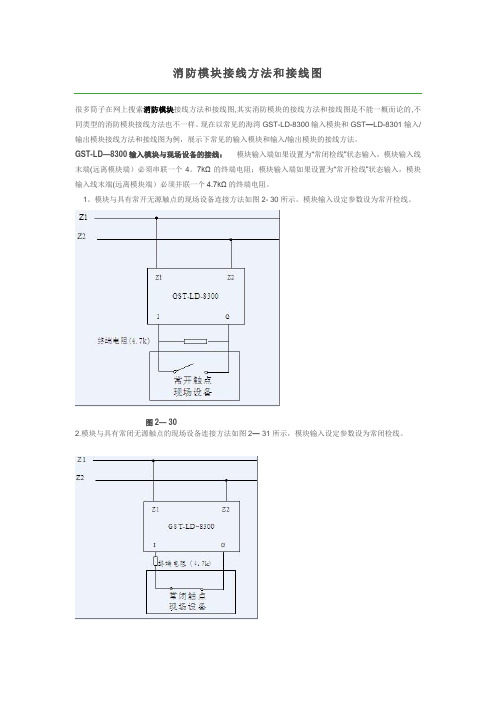
消防模块接线方法和接线图很多筒子在网上搜索消防模块接线方法和接线图,其实消防模块的接线方法和接线图是不能一概而论的,不同类型的消防模块接线方法也不一样。
现在以常见的海湾GST-LD-8300输入模块和GST—LD-8301输入/输出模块接线方法和接线图为例,展示下常见的输入模块和输入/输出模块的接线方法。
GST-LD—8300输入模块与现场设备的接线:模块输入端如果设置为“常闭检线”状态输入,模块输入线末端(远离模块端)必须串联一个4。
7kΩ的终端电阻;模块输入端如果设置为“常开检线”状态输入,模块输入线末端(远离模块端)必须并联一个4.7kΩ的终端电阻。
1。
模块与具有常开无源触点的现场设备连接方法如图2- 30所示。
模块输入设定参数设为常开检线。
图2— 302.模块与具有常闭无源触点的现场设备连接方法如图2— 31所示,模块输入设定参数设为常闭检线。
GST—LD—8301型输入/输出模块与现场设备的接线:模块输入端如果设置为“常开检线”状态输入,模块输入线末端(远离模块端)必须并联一个4.7kΩ的终端电阻;模块输入端如果设置为“常闭检线”状态输入模块输入线末端(远离模块端)必须串联一个4。
7kΩ的终端电阻.模块为有源输出时,G和NG、V+、NO 应该短接,COM、S—有源输出端应并联一个4。
7kΩ的终端电阻,并串联一个IN4007二极管。
1.模块通过有源输出直接驱动一台排烟口或防火阀等(电动脱扣式)设备的接线示意图如图2— 33 (无源常开检线输入)、图2— 34所示(无源常闭检线输入):图2- 33图2- 342。
模块无源输出触点控制设备的接线示意图如图2— 35(无源常开检线输入)、图2- 36所示(无源常闭检线输入):图2- 35。
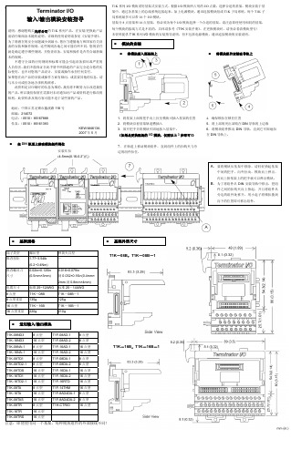
Terminator IO 输入输出模块安装指导
个 6mm 的护套
-
2000VAC/1 分钟
扩展电缆插头规格
左侧用插头
右侧用插头
I/O 地址分配方向
z 当在上例中再增加一个扩展 I/O 系统时,要使用 T1K-05CBL-LL(T1K-05CBL-LL-1)扩展电缆, 此电缆用于从左侧到左侧的连接,但注意该扩展电缆不能用做第一根扩展电缆使用。
不遵守全部的应用规则和标准可能会引起设备损坏或严重的 人员伤害。我们不能保证在此手册中所描述的产品完全适合您的实 际使用,也不对您的产品设计、安装或操作承担任何责任。 如果您在此产品的安装或操作方面有疑问,或需要其他的信息,请 与本公司或驻各地办事机构联系。
此资料是以印刷时的信息为准的。我们将不断努力以改进我们 的产品,所以我们保留在需要时未经通知对产品或资料进行修改的 权利。此资料涉及的内容可能不适于某些新的产品。
模块的安装
将模块插入到基架上
将模块组件安装在导轨上
地址:中国江苏无锡市蠡溪路 118 号 邮编:214072 电话:(0510)85167888 传真:(0510)85161393
KEW-M4613A 2007 年 5 月
在 DIN 轨道上移动模块组件到位 安装耳扣 (4-5mm(0.16-0.2”)孔)
I/O 地址分配方向
注意:此例中最后一个 扩展 I/O 系统中不能 安装电源模块(P/S)!
I/O 地址分配方向
z T1K-05CBL-RR(T1K-05CBL-RR-1)扩展电缆用于从右侧到右侧的连接。
信号 电流
注意:此例中扩展 I/O 系统中 不能安装电源模块(P/S)。
I/O 地址分配方向 信号 电流
8 点型
T1F-08DA-1
青鸟JBF5145输入输出模块使用说明书
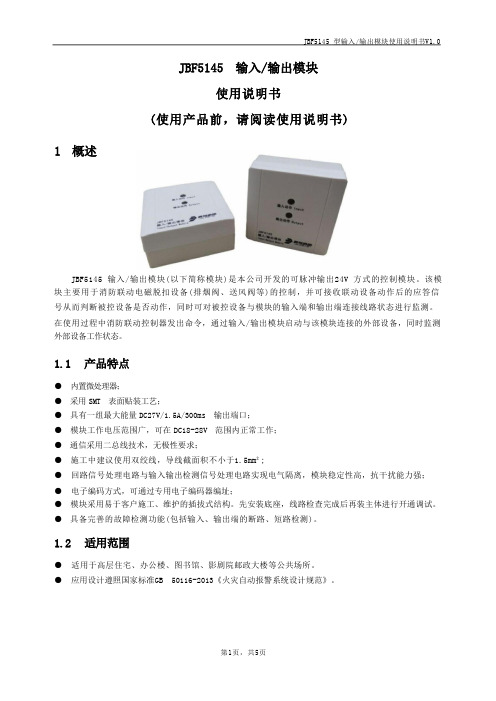
故障状态:“输入动作”灯不亮,“输出动作”灯不亮
二线制(无极性) 1~200
专用电子编码器 1500m
第2页,共5页
兼容性
JBF5145 型输入/输出模块使用说明书V1.0
1.1 产品特点
● 内置微处理器; ● 采用 SMT 表面贴装工艺; ● 具有一组最大能量 DC27V/1.5A/300ms 输出端口; ● 模块工作电压范围广,可在 DC18-28V 范围内正常工作; ● 通信采用二总线技术,无极性要求; ● 施工中建议使用双绞线,导线截面积不小于1.5mm²; ● 回路信号处理电路与输入输出检测信号处理电路实现电气隔离,模块稳定性高,抗干扰能力强; ● 电子编码方式,可通过专用电子编码器编址; ● 模块采用易于客户施工、维护的插拔式结构。先安装底座,线路检查完成后再装主体进行开通调试。 ● 具备完善的故障检测功能(包括输入、输出端的断路、短路检测)。
向上
安装
④
④
VO+
VO- S- 5
em[ 10%
eml[ 10%
1N4007
及馈 EQU
4.2 调试方法
图 3 接线示意图
● 首先使用电子编码器对JBF5145 输入/输出模块进行编码。
● 模块安装好后操作控制器对其进行登记,然后必须在系统中手动将其设置成电池储能设备。
● 进入手动启停现场设备界面,输入要启动的模块回路及地址启动,模块输出动作指示灯变为红 色常亮,被控设备动作,模块收到被控设备的无源反馈后输入动作指示灯变为红色常亮。
E-IDC1B分析型单输入小模块安装说明书

E-IDC1B Analog Single Input Mini Module Installation SheetOperationThe E-IDC1B Analog Single Input Mini Module is an analog addressable device used to connect a normally open, alarm, supervisory, or monitor type dry contact initiating device circuit (IDC) to a control panel. This module is designed for Class B circuit operation.The device address is set using the two rotary switches located on the front of the module. One device address is required.The module is factory set to operate as an alarm-latching device. When the NO contact of an initiating device is closed, an alarm signal is sent to the control panel and the alarm condition is latched at the module.Additional device types are available through front panel programming or the configuration utility. For additional information, refer to the documents listed on the control panel label.LEDsThe provides two status LEDs. The LEDs are visible from the back of the module.Figure 1: LED location1. Red LED: Alarm/active2. Green LED: Normal InstallationWARNINGS• This module does not operate without electrical power.As fires frequently cause power interruption, discussfurther safeguards with the local fire protectionspecialist.• This module does not support conventional two-wire smoke detectors.Note: The module is shipped from the factory as an assembled unit; it contains no user-serviceable parts and should not be disassembled.To install the module:1. Verify that all field wiring is free of opens, shorts, andground faults.2. Make all wiring connections as discussed in “Wiring”and shown in Figure 3.3. Set the required device address. For example, to set thedevice address for 21, set the TENS switch (marked 0to 12) to 2 and the ONES switch (marked 0 to 9) to 1.See Figure 2.The devices can be addressed from 01 to 129. Paneladdressing may vary.4. Position the module into the electrical box, behind thedevice to which it connects.Figure 2: Module address112345612111098709123456781. Insert screwdriver here© 2013 UTC Fire & Security. All rights reserved. 1 / 2 P/N 3101190 • REV 03 • REB 25JAN13WiringWire in accordance with NFPA 72 and CAN/ULC-S524,Standard for the Installation of Fire Alarm Systems and inaccordance with the local authorities having jurisdiction.Be sure to observe the polarity of the wires as shown inFigure 3.All wiring is power-limited and supervised.This module does not support two-wire smoke detectors.Figure 3: Module wiringkΩ1. Refer to the control panel technical reference manual for wiringspecifications2. Wire nut or other listed splice connector or terminal block3. Style B (Class B)4. Typical NO initiating deviceSpecificationsVoltageIDC maximum Communication line maximum 10 VDC at 350 µA 20.6 V peak-to-peakCurrentStandbyActivated 350 µA 500 µAGround fault impedance 10 kΩInitiating device circuit (IDC)EOL resistor value Circuit resistance Circuit capacitance 47 kΩ, (P/N EOL-47)50 Ω (25 Ω per wire), max.0.1 µF, max.Operating environmentTemperature Relative humidity 32 to 120°F (0 to 49°C)0 to 93%, noncondensingStorage temperature range –4 to 140°F (–20 to 60°C) Regulatory informationManufacturer Edwards, A Division of UTC Fire & SecurityAmericas Corporation, Inc.8985 Town Center Parkway, Bradenton, FL34202, USAYear ofmanufactureThe first two digits of the product serial number(located on the product identification label) arethe year of manufacture.EnvironmentalclassUL: Indoor dryNorth AmericanstandardsUL 864; CAN/ULC-S526Contact informationFor contact information, see our Web site:.2 of 2 P/N 3101190 • REV 03 • ISS 25JAN13。
单防区输入输出扩展模块安装说明书
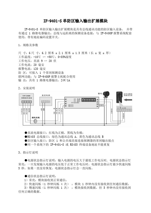
IF-9401-S单防区输入输出扩展模块IF-9401-S 单防区输入输出扩展模块是具有总线通讯功能的防区输入设备,并带有通过 1 路继电器输出;总线与远距离的探测设备连接;与 IF-9400P报警系统配套使用;带有地址编码设置开关。
1、规格及参数尺寸:6尺寸:6.2 厘米 x 2.1 厘米 x 1.3 厘米(长 x 宽 x 厚)工作温度:-10℃∽ +50℃;0-85%湿度工作电压:直流 9 ∽ 20 伏工作电流:20 毫安报警电流:120 毫安防区:可接入 1 个常闭探测设备联网功能:与 IF-9400P报警主机配合使用输出:具有 1 路继电器输出,24V/1A2、安装说明●直流电源接口:红线为正极,黑线为负极;●RS485 总线接口:绿色为通讯总线 A,黄色为通讯总线 B●防区输入接口:防区 1 和公共端直接连接探测器的常闭输出接点●同一个系统下的 IF-9401-S 或 RS485 终端设备地址不能重复3、指示灯说明●电源状态指示灯说明:输入电源的电压大于最低工作电压时, 电源状态指示灯常亮;一旦发现输入电源的电压低于正常工作电压时,电源状态指示灯最少快速闪烁5 秒,如果一直没有恢复,电源状态指示灯会一直闪烁。
●通信状态指示灯说明:1)常亮:模块接收到正常通信;2)快速闪烁(1 秒钟闪烁 4 次):模块 1 秒钟内没有接收到任何通信数据;3)慢速闪烁(1 秒钟闪烁 1 次):模块接收到数据,但 5 秒钟内没有接收到任何正确的数据。
4、地址编码开关在将 IF-9401-S 接入系统使用时,必须对其进行地址编码,编码通过编码开关按“12345678”顺序排列设置二进制地址。
例如:某防区扩展模块的编码为 13;对应的位二进制数为:00001101,在地址拨码开关对应的顺序为 1-8(即高位为 1,低位为 8)1,2,3,4,7 位不动, 5,6,8 位拨到”ON”一边附:地址编码表注意:请按照本安装指南进行安装;在连接 IF-9401-S 之前请先断开系统电源。
GST-8319输入模块安装使用说明书
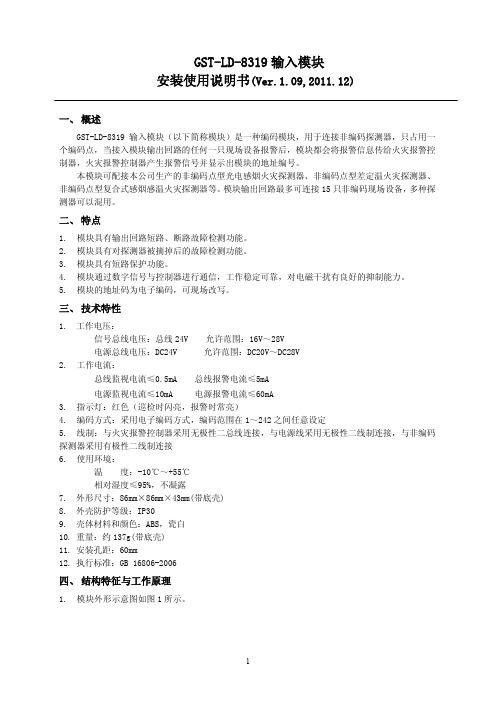
GST-LD-8319输入模块安装使用说明书(Ver.1.09,2011.12)一、概述GST-LD-8319输入模块(以下简称模块)是一种编码模块,用于连接非编码探测器,只占用一个编码点,当接入模块输出回路的任何一只现场设备报警后,模块都会将报警信息传给火灾报警控制器,火灾报警控制器产生报警信号并显示出模块的地址编号。
本模块可配接本公司生产的非编码点型光电感烟火灾探测器、非编码点型差定温火灾探测器、非编码点型复合式感烟感温火灾探测器等。
模块输出回路最多可连接15只非编码现场设备,多种探测器可以混用。
二、特点1.模块具有输出回路短路、断路故障检测功能。
2.模块具有对探测器被摘掉后的故障检测功能。
3.模块具有短路保护功能。
4.模块通过数字信号与控制器进行通信,工作稳定可靠,对电磁干扰有良好的抑制能力。
5.模块的地址码为电子编码,可现场改写。
三、技术特性1.工作电压:信号总线电压:总线24V 允许范围:16V~28V电源总线电压:DC24V 允许范围:DC20V~DC28V2.工作电流:总线监视电流≤0.5mA 总线报警电流≤5mA电源监视电流≤10mA 电源报警电流≤60mA3.指示灯:红色(巡检时闪亮,报警时常亮)4.编码方式:采用电子编码方式,编码范围在1~242之间任意设定5.线制:与火灾报警控制器采用无极性二总线连接,与电源线采用无极性二线制连接,与非编码探测器采用有极性二线制连接6.使用环境:温度:-10℃~+55℃相对湿度≤95%,不凝露7.外形尺寸:86mm×86mm×43mm(带底壳)8.外壳防护等级:IP309.壳体材料和颜色:ABS,瓷白10.重量:约137g(带底壳)11.安装孔距:60mm12.执行标准:GB 16806-2006四、结构特征与工作原理1.模块外形示意图如图1所示。
图1 模块外形示意图2.工作原理模块具有输出回路短路、断路检测功能,输出回路的末端连接终端器,当输出回路断路时,模块将故障信息传送给火灾报警控制器,火灾报警控制器显示出模块的编码地址;当输出回路中有现场设备被取下时,模块会报故障但不影响其它现场设备正常工作。
GST-LD-8301A输入输出模块安装使用说明书

安装、使用产品前,请阅读安装使用说明书一、GST-LD-8301A输入/输出模块安装使用说明书(Ver.1.04,2020.11)注意事项1.产品仅应被安装在产品安装使用说明书所明示规定的使用环境,不适用于有易燃性物质、有爆炸性物质或有腐蚀性物质的场所(包括使用磷化铝杀虫剂的烟草仓库)。
产品不可被安装在对设备有特殊认证要求的环境或场所(包括但不限于爆炸性环境、船舶、飞机、火车、机动车等交通工具)。
如有特殊需求,请联系本公司相应销售人员。
2.请注意模块输出触点只适用于控制低于48V的直流或交流,严禁用来控制AC220交流,以防强交流干扰信号损坏模块或控制设备!对于需要控制AC220V的情况,可使用GST-LD-8362H输入/输出模块实现。
3.模块输出触点端子COM和NO间有几十千欧电阻,导致工作时有微弱检线电流。
部分防火卷帘控制器、电梯控制箱等设备因其采用比较器或逻辑电平类输入、启动电流微小,容易受到线路或空间干扰自身产生误动作,不建议客户使用。
如果必须使用,应参照被控设备的说明书在GST-LD-8301A模块和被控设备间加中间继电器解决。
4.本模块不能用于控制气体灭火设备!二、概述GST-LD-8301A输入/输出模块(以下简称模块),主要用于连接需要火灾报警控制器控制的消防联动设备,如排烟阀、送风阀、防火阀等,并可接收设备的动作回答信号。
三、特点1.采用32位ARM微处理器实现信号处理,与控制器采用数字通信,工作稳定可靠,对电磁干扰具有良好抑制能力;2.输入信号隔离检测,抗干扰能力强;3.输入端可现场设为常开检线、常闭检线或自回答方式;4.地址码为电子编码,可由电子编码器事先写入,也可由控制器直接更改,工程调试简便可靠。
5.新型插拔式卡接结构,安装、拆卸简单方便,适合模块箱等多种安装方式;四、技术特性1.工作电压:信号总线电压:总线24V 允许范围:16V~28V电源总线电压:DC24V 允许范围:DC20V~DC28V2.工作电流:总线监视电流≤0.42mA 总线启动电流≤1.34mA电源监视电流≤2.00mA 电源启动电流≤18.00mA3.输入检线:常开检线时输入线路发生断路(短路为动作信号)、常闭检线时输入线路发生短路(断路为动作信号),模块将向控制器发送故障信号;4.输出检线:输出线路发生短路、断路,模块将向控制器发送故障信号;5.无源输出容量:DC30V/2A,正常时触点阻值为30kΩ,启动后闭合,适用于12V~48V直流或交流;6.输出控制方式:电平、脉冲(继电器常开触点输出,脉冲启动时继电器吸合时间为10s);7.指示灯:输入指示灯,红色,正常巡检时闪亮1次,总线电压低故障时连续闪亮两次,输入故障时以2.5Hz、50%占空比闪烁,反馈时常亮;输出指示灯:红色,待机时熄灭,输出故障时以2.5Hz、50%占空比闪烁,启动时常亮;8.编码方式:电子编码方式,占用一个总线编码点,编码范围可在1~242之间任意设定;9.线制:与火灾报警控制器采用无极性信号二总线连接,与电源线采用无极性二线制连接;10.使用环境:温度:-10℃~+55℃,相对湿度≤95%,不凝露;11.外形尺寸:86mm×86mm×41mm(带底壳);12.外壳防护等级:IP30;13.壳体材料和颜色:ABS,白色;14.重量:约96g(带底壳);15.安装孔距:60mm;16.执行标准:GB 16806-2006。
为胜智控 RS485 IO 扩展模块说明书

为胜智控RS485IO扩展模块说明书--V1.0适用于以下型号:WS-1616SWS-3200SWS-0032S产品目录第一章产品概述 (1)1.1产品概述 (1)1.2电气规格 (1)1.3使用环境及安装方式 (1)第二章产品展示 (2)2.1产品效果图 (2)2.2产品接线图 (2)第三章通讯说明 (3)3.1通信说明 (3)3.2修改模块参数 (4)第四章保修条款 (4)第一章产品概述1.1产品概述本模块使用RS485通信接口,MODBUS协议,可扩展32路开关量输入,32路晶体管输出(非隔离),16路开关量输入16路晶体管输出(非隔离)。
响应迅速,输出响应速度<1ms,输入刷新率200Hz,波特率支持600~115200。
·RS485波特率可选:600,1200,2400,4800,9600,19200,38400,115200·站号可更改:01~247,1.2电气规格:a)电源:18~28V DCb)输入端口电压:VCCc)输入端触发方式:接地d)输入端口触发电流:2mAe)输出端输出方式:下拉到comf)输出单个端口最大持续灌入电流:2Ag)输出单个端口最大瞬时电流(<=1ms)15Ah)通信接口:RS485;Modbus-RTU1.3使用环境及安装方式·为防止机器内部温度过热,请采用壁挂方式安装。
要求上下留有足够空间作为散热空间。
·可编程控制器主机和其他设备或结构物之间留50mm以上的空隙。
尽量远离高压线、高压设备和动力设备。
·避免粉尘、油污、腐蚀性环境;注意静电防护(避免手直接碰触电路板线路)。
·采用导轨安装。
第二章产品展示2.1产品效果图图2-1图2-2图2-3 2.2产品接线图图2-4图2-5图2-6第三章通讯说明3.1通迅说明3.1.1本模块使用modbus协议进行通信3.1.2支持的功能:读取寄存器a.读取线圈(0x01):可以读取当前输出的状态站号|功能码|读取地址H|读取地址L|读取数量H|读取数量L|CRC H|CRC L|例子:0101000000103D C6读取输出寄存器0开始的16个线圈的输出状态b.读取离散输入(0x02):可以读取当前输入端口的状态站号|功能码|读取地址H|读取地址L|读取数量H|读取数量L|CRC H|CRC L|例子:01020000001079C6读取当前输入寄存器地址0开始16个输入的状态c.写单个线圈(0x05):写入单个线圈站号|功能码|写入地址H|写入地址L|指令H|指令L|CRC H|CRC L|例子1:01050001FF00DD AA把Y1置一例子2:0105000100009C0A把Y1复位d.写单个寄存器(0x06):更改某个地址的寄存器的值站号|功能码|写入地址H|写入地址L|数据H|数据L|CRC H|CRC L|例子:01060000122484BD往地址为0000h的寄存器写入数据1234he.写多个线圈(0x0F):同时更改多个输出的状态站号|功能码|起始地址H|起始地址L|写入数量H|写入数量L|字节数|………………….信息…………...|CRC H|CRC L|010F00000010255551D4F从地址0h开始向输出寄存器写入16个输出的状态数据长度两个字节,数据为55hf.写多个寄存器(0x10):连续往写入多个数据寄存器写入数据站号|功能码|起始地址H|起始地址L|写入数量H|写入数量L|字节数|数据1H|数据1L|**数据**|CRC H|CRC L|0110000000020412341234BA6E从地址00h开始向数据寄存器写入两个数据,数据长度4个字节两个数据分别为1234h,1234h3.2修改模块参数(波特率,站号)3.2.1本模块的波特率和站号参数储存在数据寄存器中,只要通过modbus命令修改对应数据寄存器中的值即可修改相应的参数3.2.2波特率修改方法:波特率参数存储在数据寄存器的19h地址上,写入数据范围是00h~08h,对应9个波特率。
GST-LD-IE8301输入-输出模块安装使用说明书

一、概述GST-LD-IE8301输入/输出模块(以下简称模块),是一款功能强大、应用广泛的编码工业模块。
模块可以通过设置不同的工作模式,实现下列功能:启动消防联动设备,如排烟阀、送风阀、防火阀等,同时接收设备的动作回答信号模块不能用于气体灭火设备的控制。
模块符合GB 16806-2006中的相关规定。
二、特点1. 抗电磁干扰能力卓越。
2. 可直接控制交流220V供电设备。
3. 输入输出端均有检线功能。
4. 工作模式可通过电子编码器设置,以实现不同的功能。
5. 地址码为电子编码,可由电子编码器设置,也可由控制器更改,工程调试灵活简便。
三、技术特性1. 工作电压•总线电压:24V 允许范围:16V~28V;•电源电压:DC24V 允许范围:DC20V~DC28V。
2. 工作电流•总线电流≤0.6mA;•电源监视电流≤15mA。
3. 输出•继电器输出:一组常开/常闭触点,容量为AC220V/5A或DC30V/5A;•DC24V输出:最大输出电流为1A。
4. 指示•输入指示灯:红色,正常监视状态闪亮,有输入信号时点亮;•输出指示灯:红色,启动输出时点亮,其它状态熄灭。
5. 编码方式电子编码方式,占用一个总线编码点,编码范围可在1~242之间任意设定。
6. 工作模式:共有3种工作模式,可通过设置不同的参数来选择工作模式。
7. 使用环境•温度:-40℃~+70℃•相对湿度≤95%,不凝露•可室外使用8.壳体材料:压铸铝合金9.外形尺寸:195mm×275mm×86mm10.防护等级:IP6711.安装孔距:185mm(不使用安装板)或255mm(使用安装板),参见图2、3。
12.重量:1.87kg四、结构特征与工作原理1. 模块外形示意图如图1所示。
图1 外形示意图2. 工作原理模块内嵌两个微处理器,其中一个微处理器用于与火灾报警控制器通讯:接收火灾报警控制器的启动、复位等命令以及将模块当前的状态上传给火灾报警控制器。
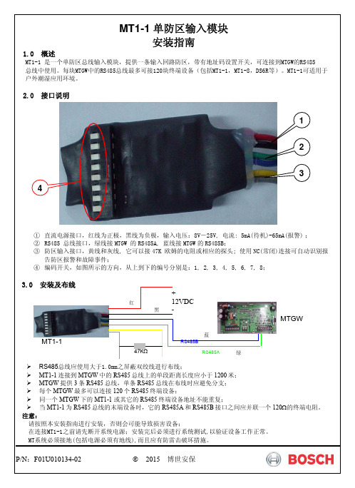
MT1-1 单防区输入模块安装指南
●=拔码开关
闭合(ON)
开关编号 2 3 4 5 6 7 8
● ● ● ● ● ● ● ● ● ● ● ● ● ● ● ● ● ● ● ● ● ● ● ● ● ● ● ● ● ● ● ● ● ● ● ● ● ● ● ● ● ● ● ● ● ● ● ● ● ● ● ● ● ● ● ● ● ● ● ● ● ● ● ● ● ● ● ● ● ● ● ● ● ● ● ● ● ● ● ● ● ● ● ● ● ● ● ● ● ● ● ● ● ● ● ● ● ● ● ● ● ● ● ● ● ● ● ● ● ● ● ● ● ● ● ● ● ● ● ● ● ● ● ● ● ● ● ● ● ● ● ● ● ● ● ● ● ● ● ● ● ● ● ● ● ● ● ● ● ● ● ● ● ● ● ● ● ● ● ● ● ● ● ● ● ●
设 备 地 址
081 082 083 084 085 086 087 088 089 090 091 092 093 094 095 096 097 098 099 100 101 102 103 104 105 106 107 108 109 110 111 112 113 114 115 116 117 118 119 120
●=拔码开关
闭合(ON)
开关编号 2 3 4 5 6 7 8
● ● ● ● ● ● ● ● ● ● ● ● ● ● ● ● ● ● ● ● ● ● ● ● ● ● ● ● ● ● ● ● ● ● ● ● ● ● ● ● ● ● ● ● ● ● ● ● ● ● ● ● ● ● ● ● ● ● ● ● ● ● ● ● ● ● ● ● ● ● ● ● ● ● ● ● ● ● ● ● ● ● ● ● ● ● ● ● ● ● ● ● ● ● ● ● ● ● ● ● ● ● ● ● ● ● ● ● ● ● ● ● ● ● ● ● ● ● ● ● ● ● ● ● ● ● ● ● ● ● ● ● ● ● ● ● ● ● ● ●
Inovonics EE1941XS EN1941XS RF模块安装和使用手册说明书
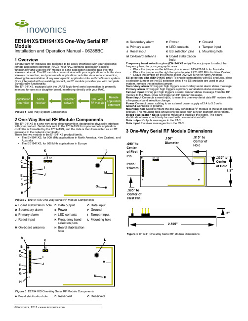
EE1941XS/EN1941XS One-Way Serial RF ModuleInstallation and Operation Manual - 06288BC 1 OverviewEchoStream RF modules are designed to be easily interfaced with your electronic remote application controller (RAC). Your RAC contains application specific functionality and uses the RF module to send application-specific data over thewireless network. The RF module communicates with your application controller via a wireless connection, and your remote application controller via a serial connection, allowing the assimilation of any user-specific application into an EchoStream system. Once integrated with an existing product, an RF module provides you with complete EchoStream functionality.The E*1941XS, equipped with the UART logic-level serial connection, is primarilyintended for use as a daughter board, interfacing directly with your RAC.Figure 1 One-Way System Components2 One-Way Serial RF Module ComponentsThe E*1941XS is a one-way serial data transmitter, designed to physically interface with your product. Serial data sent to the E*1941XS from your remote application controller is formatted by the E*1941XS, and the data is then transmitted as an RF message to the network coordinator.There are two models in the E*1941XS product family.•The EN1941XS, for 900 MHz applications in North America, New Zealand, and Australia•The EE1941XS, for 868 MHz applications in EuropeFigure 2 EN1941XS One-Way Serial RF Module Components Figure 3 EE1941XS One-Way Serial RF Module Components Frequency band selection pins (EN1941XS only) Place a jumper to select the frequency band for your geographic area.•Place the jumper on the left two pins to select 915-928 MHz for Australia.•Place the jumper on the right two pins to select 921-928 MHz for New Zealand.•Leave the jumper off the pins to select 902-928 MHz for North America.ES selection pins (EE1941XS only) To enable compatibility with ES products, place a selection jumper on the ES selection pins; if no ES products are used in your system, remove the selection jumper.Secondary alarm Driving pin high triggers a secondary serial alarm status message.Primary alarm Driving pin high triggers a primary serial alarm status message.Tamper input Driving pin high triggers a serial tamper status message from the RF module to the RAC. Does not trigger an RF tamper message.Reset input Connects a reset input, to reset the one-way serial data RF module after a frequency band selection change.Power Connect power cabling to an external power supply of 2.4 to 5.5 volts. Ground Connects to ground.Mounting hole Used to mount the one-way serial data RF module to the user-specific product. The mounting hole should only be used with a nylon standoff, never metal.Board stabilization holes Used to mount and stabilize the board. The board stabilization holes should only be used with non-metal standoffs.Data output Outputs messages to the RAC.Data input Receives messages from the RAC.3 One-Way Serial RF Module DimensionsFigure 4 E*1941 One-Way Serial RF Module DimensionsA Board stabilization hole.B Data outputC Data inputD Secondary alarmE PowerF GroundG Primary alarmH LED contactsI Tamper inputJ Reset inputK Frequency bandselection pins L Mounting holeM On-board antennaN Board stabilizationholeA Board stabilization hole.B ReservedC ReservedB C G D I JE F K LMHA OB C G D I JE F K LMHA ND Secondary alarmE PowerF GroundG Primary alarmH LED contactsI Tamper inputJ Reset inputK ES selection pinsL Mounting holeM On-board antennaN Board stabilizationhole1.3”Pitch: 2.54mm..385” to Center of First Pin.090” to Center of First Pin .335” to Center of Hole.515” to Center of Hole.156” Diameter.5”2.525”4 One-Way Serial RF Module Connections and Output Jumpers5 InstallationA The RF module must only be connected at the eight pin header or eight pin platedthru-holes.B All cables and wires must be routed away from the component side of the RFmodule.C The integrated antenna must not be tampered with; no connection to an alternateantenna is provided.D The application module must not include an integrated secondary colocated radiomodule.E The one-way serial data RF module antenna should be placed so that it is facingaway, or otherwise isolated from, your device’s ground plane.F Components that are sensitive to RF transmission, such as high gain circuits,should be isolated from the antenna to prevent interference.G One-way serial RF modules should not be mounted on metal surfaces or insidemetal enclosures. They should also not be mounted where sheet metal ductwork, wire mesh screens, etc. might block transmissions.H The RF module should be integrated so the antenna is unobstructed by the enduser’s PCB, batteries, or any other conductive material.Figure 5The RF module should be integrated so the antenna is unobstructed6 One-Way Serial RF Module Requirements6.1 Timing requirementsAll data is sent at a default rate of 9600 baud, no parity, 8 data bits and one stop bit. The data is transmitted least significant bit first.6.2 Power RequirementsThe E*1941XS has an on-board voltage regulator. Connect power cabling to an external power supply (Vcc) of 2.4 to 5.5 volts. Voltage must be sustained at 2.4 volts or above and supply 100 milliamps during the transmit cycle.EN1941XSAssuming check-in messages every 3 minutes and infrequent alarm messages (one per day, on average), the average current draw is 32 uA. Peak current draw while transmitting is less than 100 mA. One alarm/restore cycle with the maximum payload size results in approximately a 23mA increase in the average current.EE1941XSAssuming check-in messages every 12 minutes and infrequent alarm messages (one per day, on average), the average current draw is 15 uA. Peak current draw while transmitting is less than 50 mA. One alarm/restore cycle with the maximum payload size results in approximately a 12mA increase in the average current.6.3 Low Battery ConditionThe E*1941XS measures power supply voltage every three and a half hours, and, when the voltage measures 2.4 volts, a serial message is sent indicating a low battery condition.6.4 Temperature range-20°C to +60°C, non-condensing6.5 RF network compatibilityEchoStream Commercial Mesh Network6.6 Payload size50 bytes maximum6.7 Input RequirementsCaution: Input levels must not exceed 3.3 V.Open When an active source (open collector or dry contact) is used to drive the alarm or tamper input, the voltage should be between 0.75xVcc and Vcc. A passive input should have an impedance of greater than 5.1k ohm between the input and ground. Closed When an active source is used, the voltage should be less than 0.25xVcc. A passive input should have an impedance of less than 240 ohm.6.8 Serial I/O - UART logic-levelsInput levels must not exceed 3.3 V. Output levels are limited to 3.3 V, maximum. Data in pins Vih (minimum high level input voltage): 0.75xVccData in pins Vil (maximum low level input voltage): 0.25xVccData out pins Voh (minimum high level output voltage): Vcc - 0.25 at Ioh: -1.5mA Data out pins Voh (minimum high level output voltage): Vcc - 0.6 V at Ioh: -6mAData out pins Vol (maximum low level output voltage): 0.25 V at Iol: 1.5mAData out pins Vol (maximum low level output voltage): 0.6 V at Iol: 6 mA7 Compliance Requirements7.1 FCC Requirements for the EN1941XSThe EN1941XS one-way serial data RF module has received a Limited Modular Grant, requiring Inovonics to retain control of the final installation to ensure compliance to FCC/IC regulations. The integrator is responsible to test the final installation to verify compliance to FCC/IC regulation for unintentional emissions. Prior to marketing the product, the integrator must complete and submit to Inovonics a compliance review form and documentation, and, if requested, a functional product sample for approval. If this is not possible, the integrator must perform the testing themselves and submit proof to Inovonics of compliance to Part 15 of the FCC Rules and Industry Canada RSS-210.At the end of this guide is an Inovonics compliance review form to be filled out by the integrator.The integrator is also responsible for properly labeling the product containing the one-way serial data RF module. Labels must be placed on the outside of the product, and must include a statement indicating that the product contains the module, along with the FCC and IC number.Example 1 “Contains One-Way Serial RF ModuleFCC ID: HCQ3B6OT9OEM; IC ID: 2309A-OT9OEM”Example 2 “Contains FCC ID: HCQ3B6OT9OEM; IC ID: 2309A-OT9OEM”7.2 Television and Radio InterferenceThis equipment has been tested and found to comply with the limits for a Class B digital device, pursuant to Part 15 of the FCC Rules. These limits are designed to provide reasonable protection against harmful interference in a residential installation. This equipment generates, uses and can radiate radio frequency energy and, if not installed and used in accordance with the instructions, may cause harmful interference to radio communications. However, there is no guarantee that interference will not occur in a particular installation. If this equipment does cause harmful interference to radio or television reception, which can be determined by turning the equipment off and on, the user is encouraged to try to correct the interference by one or more of the following measures:•Reorient or relocate the receiving antenna.•Increase the separation between the equipment and receiver.•Connect the equipment into an outlet on a circuit different from that to which the receiver is connected.•Consult the dealer or an experienced radio/TV technician for help.8 FCC Part 15 and Industry Canada Compliance This device complies with part 15 of the FCC Rules and Industry Canada license-exempt RSS standard(s). Operation is subject to the following two conditions: (1) this device may not cause interference, and (2) this device must accept any interference, including interference that may cause undesired operation of the device.Le présent appareil est conforme aux CNR d'Industrie Canada applicables aux appareils radio exempts de licence. L'exploitation est autorisée aux deux conditions suivantes : (1) l'appareil ne doit pas produire de brouillage, et (2) l'utilisateur del'appareil doit accepter tout brouillage radioélectrique subi, même si le brouillage est susceptible d'en compromettre le fonctionnement.Connection Output Jumper N/C Primary AlarmOpen AlarmGround Alarm ClearSecondary Alarm Open Alarm Ground Alarm ClearTamperOpen TamperGround Tamper ClearReset Open for normal operation; connect to the ground and release for a board reset.End user application printed circuit board RF moduleClear transmit region in front and back of antenna8.1 CE Label Requirements for EE1941XSInovonics Wireless has received European Telecommunications Standards Institute approval to market one-way serial data RF modules, and they are manufactured to be RoHS compliant. The integrator is responsible for properly labeling the product containing the one-way serial data RF module. Labels must be placed on the outside of the product, and must include the CE logo.9 Warranty and DisclaimerNote: Changes or modifications not expressly approved by the party responsible for compliance could void the user's authority to operate the equipment.Inovonics Wireless Corporation ("Inovonics") warrants its EchoStream products ("Product" or "Products") to conform to its own specifications and to be free of defects in materials and workmanship under normal use for a period of thirty-six (36) months from the date of manufacture. Within the warranty period, Inovonics will repair or replace, at its option, all or any part of the warranted Product. Inovonics will not be responsible for dismantling and/or reinstallation charges. To exercise the warranty, the User ("User", "Installer" or "Consumer") must work directly through their authorized distributor who will be given a Return Material Authorization ("RMA") number by Inovonics. Details of shipment will be arranged directly through the authorized distributor.This warranty is void in cases of improper installation, misuse, failure to follow installation and operating instructions, alteration, accident or tampering, and repair by anyone other than Inovonics.This warranty is exclusive and expressly in lieu of all other warranties, obligations or liabilities, whether written, oral, express, or implied. There is no warranty by Inovonics that Inovonics product will be merchantable or fit for any particular purpose, nor is there any other warranty, expressed or implied, except as such is expressly set forth herein. In no event shall Inovonics be liable for an incidental, consequential, indirect, special, or exemplary damages, including but not limited to loss of profit, revenue, or contract, loss of use, cost of down time, or interruption of business, nor any claim made by distributor's customers or any other person or entity.This warranty will not be modified or extended. Inovonics does not authorize any person to act on its behalf to modify or extend this warranty.This warranty will apply only to Inovonics Products. Inovonics will not be liable for any direct, incidental, or consequential damage or loss whatsoever, caused by the malfunction of Product due to products, accessories, or attachments of other manufacturers, including batteries, used in conjunction with Inovonics Products.Inovonics One-Way Serial RF Module Compliance Review FormPlease provide the following information for review of final installation toensure compliance with FCC/IC regulations:Required materials from integratorThe following must also be attached for review with this form:• A description of the final installation, with attached photographs, asnecessary•The unintentional radiator test report indicating compliance Integrator informationFirst name:Last name:Phone number:Email address:Address:Declaration of conformity to Inovonics’ installation instructions:Submitted materials:Authorized signature:Submission date:Inovonics contact informationInovonicsATTN: Product Management315 CTC Blvd.Louisville, CO 80027Phone: 303.939.9336Toll-Free: 800.782.2709Fax: 303.939.8977*****************************Required materials from Inovonics•The record of product sample review and test, as necessary Inovonics approvalFirst name:Last name:Phone number:Email address:Approval status (pass, fail, samples required, compliance testing required, compliance test report required):Approval comments:Submitted materials:Returned materials:Authorized signature:Approval date:。
依爱消防安装调试维护说明书

火灾报警系统能否长期稳定地运行,取决于产品可靠的质量、规范的安装、全面的调试、定期的测试以及适时的维护,缺一不可!在实际工程中,常因布线不规范、部件安装不正确或其它原因造成系统运行不正常,甚至不能顺利通过验收,给工程安装公司和使用单位造成一定的损失,也对设备供应单位的声誉造成一定的影响。
为了提高广大工程技术人员和现场施工人员排查解决故障的能力,我们专门组织具有多年工程实践经验的专业技术人员对施工、调试过程中的常见问题及解决办法进行整理,汇编成册,供大家学习、参考,希望能对大家的安装、调试、维护工作起到一定的指导作用。
本手册内容主要包括消防系统的布线、部件安装、调试、常见故障排查、工程案例及附录等,具有较强的针对性和实用性。
本手册在编写过程中得到了公司领导的大力支持,得到了技术部门和工程服务部门的全力配合,在此一并表示感谢。
本手册内容虽经反复推敲、认真校对,但仍难免有疏漏和不妥之处,欢迎大家提出宝贵意见和建议,以便今后修正。
第一章布线及常用部件接线简图第一章布线为保证系统安全、稳定、可靠地运行,必须选择合适的导线并正确安装,使用的导线要符合电气要求和安全要求,接线应牢固可靠,接头应镀锡或使用冷压端子。
一、线型选择:请参考以下要求进行购买1.两总线(信号线)(1)可使用导线类型:阻燃铜芯绝缘双绞型软导线(ZR-RVS)(2)线芯截面积≥ 1 mm2(3)最远传输距离:2000米由于双绞线比平行导线具有更好的抗干扰性能,为了保障系统的可靠运行,两总线必须使用双绞线。
在高压、强磁场等恶劣环境下,应选用屏蔽线;在潮湿的环境,应选用护套线。
2.联动控制线(直接输出联动线)(1)可使用导线类型:多股铜芯绝缘阻燃双绞型软导线ZR-RVS(2)线芯截面积≥ 1.5mm2(3)最远传输距离:2000米3.24V电源线(1)可使用导线类型:铜芯绝缘双绞型软导线(RVS)或铜芯绝缘软导线(RVB、BVR)(2)线芯截面积≥1.5 mm2(3)最远传输距离:1500米(4)对于具体工程,还应根据具体负载电流、导线长度及被控设备最低工作电压的要求来选取导线线径。
- 1、下载文档前请自行甄别文档内容的完整性,平台不提供额外的编辑、内容补充、找答案等附加服务。
- 2、"仅部分预览"的文档,不可在线预览部分如存在完整性等问题,可反馈申请退款(可完整预览的文档不适用该条件!)。
- 3、如文档侵犯您的权益,请联系客服反馈,我们会尽快为您处理(人工客服工作时间:9:00-18:30)。
IF-9401-S单防区输入输出扩展模块
IF-9401-S 单防区输入输出扩展模块是具有总线通讯功能的防区输入设备,并带有通过 1 路继电器输出;总线与远距离的探测设备连接;与 IF-9400P报警系统配套使用;带有地址编码设置开关。
1、规格及参数
尺寸:6尺寸:6.2 厘米 x 2.1 厘米 x 1.3 厘米(长 x 宽 x 厚)
工作温度:-10℃∽ +50℃;0-85%湿度
工作电压:直流 9 ∽ 20 伏
工作电流:20 毫安
报警电流:120 毫安
防区:可接入 1 个常闭探测设备
联网功能:与 IF-9400P报警主机配合使用
输出:具有 1 路继电器输出,24V/1A
2、安装说明
●直流电源接口:红线为正极,黑线为负极;
●RS485 总线接口:绿色为通讯总线 A,黄色为通讯总线 B
●防区输入接口:防区 1 和公共端直接连接探测器的常闭输出接点
●同一个系统下的 IF-9401-S 或 RS485 终端设备地址不能重复
3、指示灯说明
●电源状态指示灯说明:输入电源的电压大于最低工作电压时, 电源状态指示灯常亮;一旦发现输入电源的电压低于正常工作电压时,电源状态指示灯最少快速闪烁5 秒,如果一直没有恢复,电源状态指示灯会一直闪烁。
●通信状态指示灯说明:
1)常亮:模块接收到正常通信;
2)快速闪烁(1 秒钟闪烁 4 次):模块 1 秒钟内没有接收到任何通信数据;
3)慢速闪烁(1 秒钟闪烁 1 次):模块接收到数据,但 5 秒钟内没有接收到任何正确的数据。
4、地址编码开关
在将 IF-9401-S 接入系统使用时,必须对其进行地址编码,编码通过编码开关按“12345678”顺序排列设置二进制地址。
例如:某防区扩展模块的编码为 13;对应的位二进制数为:00001101,在地址拨码开关对应的顺序为 1-8(即高位为 1,低位为 8)
1,2,3,4,7 位不动, 5,6,8 位拨到”ON”一边
附:地址编码表
注意:请按照本安装指南进行安装;在连接 IF-9401-S 之前请先断开系统电源。
