GYJ-0040_6路输入输出(NPN输入型)产品使用说明书
六管四合一双模无刷控制板说明书
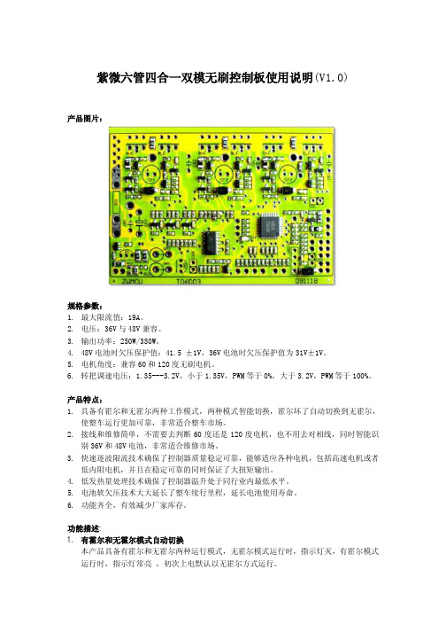
紫微六管四合一双模无刷控制板使用说明(V1.0)产品图片:规格参数:1.最大限流值:19A。
2.电压:36V与48V兼容。
3.输出功率:250W/350W。
4.48V电池时欠压保护值:41.5 ±1V,36V电池时欠压保护值为31V±1V。
5.电机角度:兼容60和120度无刷电机。
6.转把调速电压:1.35---3.2V,小于1.35V,PWM等于0%,大于3.2V,PWM等于100%。
产品特点:1.具备有霍尔和无霍尔两种工作模式,两种模式智能切换,霍尔坏了自动切换到无霍尔,使整车运行更加可靠,非常适合整车市场。
2.接线和维修简单,不需要去判断60度还是120度电机,也不用去对相线,同时智能识别36V和48V电池,非常适合维修市场。
3.快速逐波限流技术确保了控制器质量稳定可靠,能够适应各种电机,包括高速电机或者低内阻电机,并且在稳定可靠的同时保证了大扭矩输出。
4.低发热量处理技术确保了控制器温升处于同行业内最低水平。
5.电池软欠压技术大大延长了整车续行里程,延长电池使用寿命。
6.功能齐全,有效减少厂家库存。
功能描述:1.有霍尔和无霍尔模式自动切换本产品具备有霍尔和无霍尔两种运行模式,无霍尔模式运行时,指示灯灭,有霍尔模式运行时,指示灯常亮,初次上电默认以无霍尔方式运行。
如何从无霍尔模式切换到有霍尔模式接好电机霍尔线,加转把等电机转动后,只要检测到电机霍尔正常,控制器就会切换到有霍尔模式,以后上电只要控制器霍尔正常都以有霍尔模式运行。
如何从有霍尔模式切换到无霍尔模式如果电机转动,只要检测到电机霍尔损坏,控制器会马上切换到无霍尔模式。
如果电机不转,而电机霍尔拔掉或者损坏,必须释放转把,并且人为转动一下电机,才会切换到无霍尔模式。
如何切换电机运行方向先切换到无霍尔模式(释放转把,拔掉霍尔,并且转动一下电机),调换无刷电机任意两根相线,加调速转把,电机就以相反方向运行。
2.36V与48V电池自动识别上电识别: 如果处于无霍尔模式,则控制器上电后,检测电池电压大于41.5V就认为是48V电池,否则就认为36V电池;如果是有霍尔模式则调用上次记忆。
JTS-400城轨静调电源柜(STINGER)说明书_德飞电气

使用说明书株洲德飞电气有限公司Zhuzhou Dephi Eelectric Co., Ltd名称 JTS-400/1500(750) 城轨静调电源柜(STINGER)编号 DP2010071801A001版本A0JTS-400/1500城轨静调电源柜(STINGER) _使用说明书版本号 更改人更改日期更改说明变更编号编 制 工 艺 校 核 标准化 审 核 批 准目 录1 安全2 参照标准3 技术规格4 产品功能5 电气连接6 安装及机械尺寸7 技术条件8 操作与使用9 故障处理10 指示灯定义11 使用安全注意事项关于本使用说明书本使用说明书是关于“静调电源柜(STINGER)”的内容,包括有关安装、使用、维护的所有必要的信息。
建议您在安装使用前仔细阅读本使用说明书。
关于本产品本产品由STINGER柜体及柜顶的警报灯组成,该柜可通过列车电源箱给列车提供1500VDC或750VDC电压,以满足检修需要。
JTS-400/1500(750)系列地铁静调电源柜(Stinger)可为地铁车辆提供DC1500V或DC750V 电源,从外部获得DC1500V或DC750V电源、AC220V电源,在满足地铁车辆电气设备及车辆、空调的维修调试需求的同时,输出满足车辆电源要求的 DC1500V或DC750V电源,主要作用是通过电路控制来通断直流电源,在车辆负载短路情下快速、自动分断电源避免车辆短路对电网、车辆的破坏。
1安全只有合格的专业电气技术人员才能从事以下本产品的安装、调试和维护工作。
该产品采用了以下安全措施:1)仅在从STINGER柜引出的电缆插头与车辆电源箱插座连接好后,1500V或750V电压才能从STINGER柜送出。
2)1500V或750V电压从STINGER柜送出后,柜顶警报灯闪烁。
3)STINGER柜柜外可装紧急分闸按钮,按下将使STINGER柜停止工作并使其紧急分断1500VDC或750VDC电源,同时电笛报警(可按STINGER柜上的“复位按钮”按钮解除报警)。
放大器内置型光电传感器

导线引出式 2 导线引出式 2 导线引出式 0.2 导线引出式 2 M12 插接件 M12 插接件 导线引出式 2 导线引出式 2 M12 插接件 M12 插接件 导线引出式 5 导线引出式 2 导线引出式 2 导线引出式 2 M12 插接件 M12 插接件 导线引出式 2 导线引出式 2 M12 插接件 M12 插接件 -
460 传感器
光电开关
放大器内置型光电传感器
E3F3系列(螺纹柱状光电传感器): ●● 具有光电 - IC 技术的抗干扰性;M18DIN - 大小的柱状外罩,ABS树脂盒 ●● BRASS外壳具有传感距离长,带灵敏度调节器的反射性产品 ●● 电源短路和逆接保护 ●● 电源电压:DC12-24V ●● 防护等级:IP66
连接方式 导线长度(m) 外壳材料 检测距离(mm)
输出方式 输出状态
导线引出式 2 导线引出式 2 导线引出式 2 导线引出式 2 M12插接件 M12插接件 M12插接件 M12插接件 导线引出式 2 导线引出式 2 导线引出式 2 导线引出式 2 M12插接件 M12插接件 M12插接件 M12插接件 导线引出式 2 导线引出式 2 导线引出式 2 导线引出式 2 M12插接件 M12插接件 M12插接件 M12插接件 导线引出式 2 导线引出式 2 导线引出式 2 M12插接件 M12插接件 M12插接件 M12插接件 -
欧姆朗电子GY5000电磁漏电保护器产品说明书

Dimensions: [mm]71610749118201274911820127491182012T e m p e r a t u r eT T T 7491182012Cautions and Warnings:The following conditions apply to all goods within the product series of WE-UNIT ofWürth Elektronik eiSos GmbH & Co. KG:General:•This electronic component is designed and manufactured for use in general electronic equipment.•Würth Elektronik must be asked for written approval (following the PPAP procedure) before incorporating the components into any equipment in fields such as military, aerospace, aviation, nuclear control, submarine, transportation (automotive control, train control, ship control), transportation signal, disaster prevention, medical, public information network, etc. where higher safety and reliability are especially required and/or if there is the possibility of direct damage or human injury.•Electronic components that will be used in safety-critical or high-reliability applications, should be pre-evaluated by the customer.•The component is designed and manufactured to be used within the datasheet specified values. If the usage and operation conditions specified in the datasheet are not met, the wire insulation may be damaged or dissolved.•Do not drop or impact the components, as the component may be damaged.•Würth Elektronik products are qualified according to international standards, which are listed in each product reliability report. Würth Elektronik does not warrant any customer qualified product characteristics beyond Würth Elektronik's specifications, for its validity and sustainability over time.•The responsibility for the applicability of the customer specific products and use in a particular customer design is always within the authority of the customer. All technical specifications for standard products also apply to customer specific products.Product specific:Soldering:•The solder profile must comply with the technical product specifications. All other profiles will void the warranty.•All other soldering methods are at the customers’ own risk.Cleaning and Washing:•Washing agents used during the production to clean the customer application might damage or change the characteristics of the wire insulation, marking or plating. Washing agents may have a negative effect on the long-term functionality of the product. Potting:•If the product is potted in the customer application, the potting material might shrink or expand during and after hardening. Shrinking could lead to an incomplete seal, allowing contaminants into the core. Expansion could damage the component. We recommend a manual inspection after potting to avoid these effects.Storage Conditions:• A storage of Würth Elektronik products for longer than 12 months is not recommended. Within other effects, the terminals may suffer degradation, resulting in bad solderability. Therefore, all products shall be used within the period of 12 months based on the day of shipment.•Do not expose the components to direct sunlight.•The storage conditions in the original packaging are defined according to DIN EN 61760-2.•The storage conditions stated in the original packaging apply to the storage time and not to the transportation time of the components. Handling:•Violation of the technical product specifications such as exceeding the nominal rated current will void the warranty.•Applying currents with audio-frequency signals may result in audible noise due to the magnetostrictive material properties.•Due to heavy weight of the components, strong forces and high accelerations may have the effect to damage the electrical connection or to harm the circuit board and will void the warranty.•The temperature rise of the component must be taken into consideration. The operating temperature is comprised of ambient temperature and temperature rise of the component.The operating temperature of the component shall not exceed the maximum temperature specified.These cautions and warnings comply with the state of the scientific and technical knowledge and are believed to be accurate and reliable.However, no responsibility is assumed for inaccuracies or incompleteness.Würth Elektronik eiSos GmbH & Co. KGEMC & Inductive SolutionsMax-Eyth-Str. 174638 WaldenburgGermanyCHECKED REVISION DATE (YYYY-MM-DD)GENERAL TOLERANCE PROJECTIONMETHODCHC004.0012021-01-20DIN ISO 2768-1mDESCRIPTIONWE-UNIT Off-Line TransformerORDER CODE7491182012SIZE/TYPE BUSINESS UNIT STATUS PAGEImportant NotesThe following conditions apply to all goods within the product range of Würth Elektronik eiSos GmbH & Co. KG:1. General Customer ResponsibilitySome goods within the product range of Würth Elektronik eiSos GmbH & Co. KG contain statements regarding general suitability for certain application areas. These statements about suitability are based on our knowledge and experience of typical requirements concerning the areas, serve as general guidance and cannot be estimated as binding statements about the suitability for a customer application. The responsibility for the applicability and use in a particular customer design is always solely within the authority of the customer. Due to this fact it is up to the customer to evaluate, where appropriate to investigate and decide whether the device with the specific product characteristics described in the product specification is valid and suitable for the respective customer application or not.2. Customer Responsibility related to Specific, in particular Safety-Relevant ApplicationsIt has to be clearly pointed out that the possibility of a malfunction of electronic components or failure before the end of the usual lifetime cannot be completely eliminated in the current state of the art, even if the products are operated within the range of the specifications.In certain customer applications requiring a very high level of safety and especially in customer applications in which the malfunction or failure of an electronic component could endanger human life or health it must be ensured by most advanced technological aid of suitable design of the customer application that no injury or damage is caused to third parties in the event of malfunction or failure of an electronic component. Therefore, customer is cautioned to verify that data sheets are current before placing orders. The current data sheets can be downloaded at .3. Best Care and AttentionAny product-specific notes, cautions and warnings must be strictly observed. Any disregard will result in the loss of warranty.4. Customer Support for Product SpecificationsSome products within the product range may contain substances which are subject to restrictions in certain jurisdictions in order to serve specific technical requirements. Necessary information is available on request. In this case the field sales engineer or the internal sales person in charge should be contacted who will be happy to support in this matter.5. Product R&DDue to constant product improvement product specifications may change from time to time. As a standard reporting procedure of the Product Change Notification (PCN) according to the JEDEC-Standard inform about minor and major changes. In case of further queries regarding the PCN, the field sales engineer or the internal sales person in charge should be contacted. The basic responsibility of the customer as per Section 1 and 2 remains unaffected.6. Product Life CycleDue to technical progress and economical evaluation we also reserve the right to discontinue production and delivery of products. As a standard reporting procedure of the Product Termination Notification (PTN) according to the JEDEC-Standard we will inform at an early stage about inevitable product discontinuance. According to this we cannot guarantee that all products within our product range will always be available. Therefore it needs to be verified with the field sales engineer or the internal sales person in charge about the current product availability expectancy before or when the product for application design-in disposal is considered. The approach named above does not apply in the case of individual agreements deviating from the foregoing for customer-specific products.7. Property RightsAll the rights for contractual products produced by Würth Elektronik eiSos GmbH & Co. KG on the basis of ideas, development contracts as well as models or templates that are subject to copyright, patent or commercial protection supplied to the customer will remain with Würth Elektronik eiSos GmbH & Co. KG. Würth Elektronik eiSos GmbH & Co. KG does not warrant or represent that any license, either expressed or implied, is granted under any patent right, copyright, mask work right, or other intellectual property right relating to any combination, application, or process in which Würth Elektronik eiSos GmbH & Co. KG components or services are used.8. General Terms and ConditionsUnless otherwise agreed in individual contracts, all orders are subject to the current version of the “General Terms and Conditions of Würth Elektronik eiSos Group”, last version available at .Würth Elektronik eiSos GmbH & Co. KGEMC & Inductive SolutionsMax-Eyth-Str. 174638 WaldenburgGermanyCHECKED REVISION DATE (YYYY-MM-DD)GENERAL TOLERANCE PROJECTIONMETHODCHC004.0012021-01-20DIN ISO 2768-1mDESCRIPTIONWE-UNIT Off-Line TransformerORDER CODE7491182012SIZE/TYPE BUSINESS UNIT STATUS PAGE。
XH9992E-2S4说明书(六路开关量输入)
5
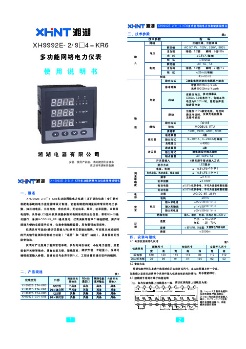
湘 湖 XH9992E-2/9□4-KR6多功能网络电力仪表使用说明书
4.3.3 电能脉冲输出:P+为有功电能脉冲输出+端,Q+为无功电能脉冲输出+ 端,P-Q-为有功/无功电能脉冲输出-端,输出方式为集电极开路的光耦输出, 集电极开路电压VCC≤48V,电流Iz≤50mA。电能脉冲输出对应于二次侧数 据,计算一次侧电能时,需乘以电压互感器倍率PT和电流互感器倍率CT才能 得出一次侧数据。 4.3.4 开关量输入(DI input):DI1~DI6为1~6路无源干接点输入端,仪表 内部自带+5V电源。
A B C N
电压直接接入 、电流 直接接 入
UA UB UC UN IA* IA IB* IB IC* IC
A
*
B
*
C
*
N
电压经互 感器接 入、电 流 经互 感 器接入
UA UB UC UN IA* IA IB* IB IC* IC
A
*
B
*
C
*
N
电 压直接接入 、电流 经 互感器 接 入
UA UB UC UN IA* IA IB* IB IC* IC
仪表接线、仪表编程中设置的输入网络nEt应该与所测量的负载的接线方式一致。
3
湘湖 XH9992E-2/9□4-KR6多功能网络电力仪表使用说明书
波士 电子
RS-2 32/RS-48 5转换 器
型号:U4 8 5C
五、编程与使用
5.1 面板说明
12 0Ω
三 排L ED
k:千 M:兆 标 识 测量 数 据的数 量级 标 识 当前 显 示的 测 量 项目
out1out2为两路开关量输出端口功能模块安装后有效kr6多功能网络电力仪表使用说明书xh9992ekr6多功能网络电力仪表使用说明书四安装与接线41外形及安装开孔尺寸仪表外形42方形9696方形12096120961109111091801001129211292面板尺寸壳体尺寸安装开孔尺寸显示方式电压电流有功功率无功功率视在功率频率功率因数有功电能无功电能范围绝缘电阻温度湿度海拔功耗输出方式协议波特率通道数量输出方式负载能力通道数量输出方式触点容量输入和电源输入和输出输出和电源耐压在额定电压参比频率及cos10的条件下负载工作电流为0001in时能起动并连续计量电能当施加115额定电压电流回路无电流时仪表无电能累加及脉冲输出rs485modbusrtu1200240048009600020ma420ma可编程400?继电器常开触点输出ac240v1a05fs1个字05fs1个字01hz001pf05仅供参考不作为计量收费依据20仅供参考不作为计量收费依据led显示acdc85264v5va2kv50hz1mi1kv50hz1mi2kv50hz1mi工作
天津曙光敬业科技有限公司数字开关说明书

本说明书由天津曙光敬业科技有限公司翻译This manual has been translated by Tianjin Aurora UA V Technology Co.,Ltd.尊敬的用户,欢迎购买我们的数字开关。
此产品是世界上第一个多功能开关系统,由PowerBox Systems GmbH研发、生产。
它专门使用轻巧的锂电池,在接收机电源供应的开关安全性上有很大改善。
此产品外壳坚固并带有一个自锁电子开关、一个高性能线性IC控制稳压电路和一个电压监测器。
此电压监测器使用一个两芯锂电池和一个五芯镍镉/镍氢电池组,分四个阶段进行监测。
重要的构造特点:坚固的塑料外壳(材质为30%的玻璃纤维)、两根连接导线、一根横截面为0.34mm2的硅导线直接焊接在焊接板上(如在同一直线上),焊接板封装在专用的胶层中以防振、SMT安装电路板、编程控制的线路转换程序以及两个散热片(其中一个焊接在电路板上)。
我们建议将数字开关用于以下类型的模型:-带有五个标准尺寸舵机的中小型模型飞机-F3A模型(非常适用于此模型)-带有八个或八个以上舵机的滑翔机,依据舵机尺寸、模型尺寸和飞行类型(热飞行或特技飞行)-电力驱动或光驱动的直升机,转子直径为1.30m,最多带有五个舵机-电力驱动或光驱动的RC模型汽车-模型船-汽油机点火系统的电压为四芯镍镉电池的电压(DA或其它)操作:数字开关由一个按钮控制,操作起来非常简便。
此按钮也用来设置想要安装的电池的开关。
在一般情况下,此按钮负责将开关信号传输给电子开关;按钮本身与实际的电流转换没有关系。
将一个两芯锂电池或一个五芯镍镉/镍氢电池与电池导线连接。
此导线装有一个极化通用接头。
注意,应将电池极性连接正确。
注意:将电池极性接反会损坏开关中的集成稳压器IC。
连接好电池后,LED指示灯会亮起来并显示电池的电压:绿色表示电压正常,橙色表示半放电,红色表示电量不足。
当自锁电子开关连接到电源时,其默认状态为“ON”。
欧真喷水织机系统集成电控使用说明书-V2.2

欧真喷水织机集成电控使用说明书(简易版)V2.2欧真自动化科技(上海)有限公司OG‐WS100喷水电控是集成化、一体化电控系统,可模块化配置电子卷取、电子送经、电子双送经,以及单喷、双喷电子储纬器。
系统核心采用高速ARM芯片,数字化管理各子系统,集成化程度高,实时控制能力强,并采用高精度编码器,精确同步和协调各系统工作,达到精准化控制。
系统电气优化布局,采用先进的电源管理技术,温升大大降低,同时使用的大量抑制电磁干扰和抗干扰措施,减小各系统间的电磁干扰,系统稳定性强。
系统采用统一的7寸彩色液晶屏,各子系统所有参数和设置都可以通过一个屏幕解决,简化了操作过程,提高了使用效率。
OG‐WS100集成化电控真正做到一体化、数字化、模块化,是一套稳定、可靠、高效的系统化产品。
一、 使用须知在使用之前,请您详细阅读本说明书,以确保正确使用本产品。
请将本说明书妥善保管,以便随时查阅。
1.在使用之前,请注意以下事项:输入电源:规格1:AC380V±15%, 50/60HZ;规格2:AC415V±15%, 50/60HZ;两种规格内部接线稍微不同。
请务必安全接地。
使用环境温度:0~45℃。
使用环境湿度:20~90%(无结露)存放环境温度:‐10~60℃。
存放环境湿度:20~90%(无结露)带慢速功能的电控,请按本说明书正确接入变频电源。
2.在使用时,请注意以下事项:通电状态,请勿打开电箱,请勿触摸电箱内部部件,以免烫伤或触电。
断电后5分钟内,请勿打开电箱,请勿触摸电箱内部部件,以免触电。
30分钟内请勿触摸带有发热标志的部件,以免烫伤。
非专业人员请勿擅自拆卸和维修电箱内部部件。
有故障无法排除或需要维修,请联系厂家。
二、 接口说明1.电箱布局(图2.1)说明:a)电子卷取伺服驱动器、电子送经1伺服驱动器和电子送经2伺服驱动器,根据需要进行配置,和当前图示可能有所不同。
b)图示为带变频慢速功能的电控,如无变频慢速功能,则接触器MSH及配套线束不安装。
河南濮阳静探仪说明书jty-4
第一章操作步骤1.1 准备工作在操作本仪器前请进行一系列检查及准备工作。
1、打开盖,观察面板及各部分操作调节件是否完整,有无撞击伤痕,各插座是否有杂物及铁屑,进行清洁处理。
2、打开电源开关,观察指示灯,如欠电灯和电源灯同时亮,应进行充电后再使用。
3、打开电源开关,显示屏的字体显示如较黑或无字,字体显示清晰后使用。
1.2 面板的识别与操作本仪器的面板包括开关、插座和键盘三个部分。
键盘采用密封触摸式键盘,外观精美,操作方便,具有防尘、防水、防震、防有害气体侵蚀的特点。
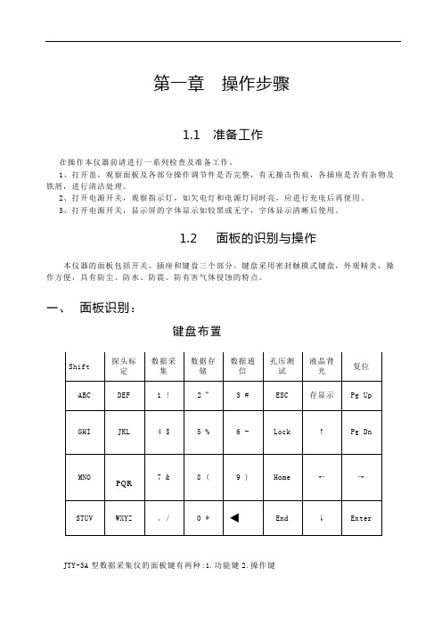
一、面板识别:键盘布置JTY-3A型数据采集仪的面板键有两种:1.功能键2.操作键整个键盘区按功能分四部分:1、五个发光灯。
2、11个数字键。
3、8个字母键。
4、21个功能键。
二、发光灯:1、电源灯打开电源开关,机器正常,电源灯亮。
2、欠电灯电池电压较低电量不足时,欠电灯亮3、充电灯当充电电源接通时,充电灯亮。
4、充足灯当充电完成时,充足灯亮。
5、Shift灯Shift灯亮进入字母小写/数字键上的符号输入。
三、功能键:接通仪器电源后,按功能键即可进入该功能的运行过程。
1、探头标定:可以率定静力触探头的锥尖和侧壁,得到锥尖和侧壁的率定系数。
2、数据采集:按此功能键即可实现静探数据的自动采集。
3、数据通信:将仪器的数据通信到PC机中。
4、数据存储:将采集到的数据存进仪器的存储芯片中,长期保存。
5、孔压测试:直接起动孔压测试程序。
6、液晶背光:开启/关闭液晶屏的背光。
仪器进入调零或采集状态时,禁止按"液晶背光"键。
7、存显示:显示仪器各存储区(A-F)的占用情况。
8、Shift :输入字母时大写/小写转换键。
数字键上的符号输入。
四、操作键:1、数字键:按0-9即可输入该数字。
输入小数点时按“.”。
2、字母键:A-Z,按字母键,依次循环出现键面上的所有字母。
3、光标键:键名上所示的方向,表示光标移动的方向可将光标移动到欲修改数据的地方。
4、ESC :退回到上一层程序菜单。
GYJ-0136_8路输入输出(NPN输入型)产品使用说明书
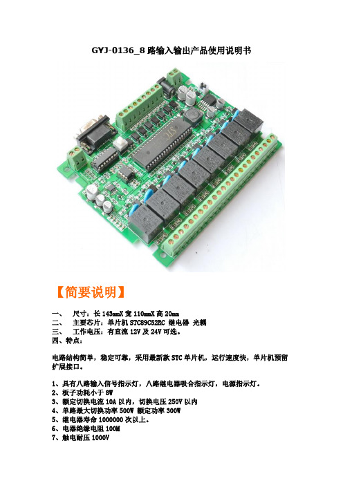
GYJ-0136_8路输入输出产品使用说明书【简要说明】一、尺寸:长143mmX宽110mmX高20mm二、主要芯片:单片机STC89C52RC 继电器光耦三、工作电压:有直流12V及24V可选。
四、特点:电路结构简单,稳定可靠,采用最新款STC单片机,运行速度快,单片机预留扩展接口。
1、具有八路输入信号指示灯,八路继电器吸合指示灯,电源指示灯。
2、板子功耗小于8W3、额定切换电流10A以内,切换电压250V以内4、单路最大切换功率500W 额定功率300W5、继电器寿命1000000次以上。
6、电器绝缘电阻100M7、触电耐压1000V8、继电器最大吸合时间15mS 毫秒9、继电器最大释放时间5mS 毫秒10、工作温度-40度至+70度11、工作湿度40% ~ 80%RH12、8路光电隔离输入,8路光电隔离输出13、8输入低电平有效(即:NPN输入)14、8路输出开关量输出(即:干接点输出)15、具有MAX232通讯和RS485通讯两种模式可选。
16、单片机所有IO口都引出,客户可以自己编程扩展功能17、可以选择使用外部EEPROM 作为存储单元18、电路具有,防反接保护、过流保护、续流保护、压敏保护等19、单片机可以自行更换,可以选择替换型的STC系列单片机20、我们提供电路相关的,原理图、例程、开发环境、下载软件等相关资料适用场合:工业控制、产品开发、项目设计,自动化改造等【标注说明】【接线说明】【输入控制设备】【输出控制设备】【输出举例说明】【输出举例说明】(开关量输出、干接点输出)【专业下载线接线说明】【串口通信说明】也可以通过串口下载【485通信说明】【MAX232与485通信切换说明】【扩展接口说明】(我们会在陆续增加、模拟量输入模块、电流模块、电压模块、无线模块、数码管显示模块、液晶模块、按键模块、PWM模块、模拟量输出模块、wifi模块、CAN模块、IP 模块等等。
)【原理图】(提供PDF格式的原理图及PCB图)更清晰免费提供与此工控板有关的:资料、例程、原理图芯片资料、软件。
400KVA 60Hz变频电源用户使用手册---雷乐士

外部保护: __________________________________________________________________________________ 5 远程控制和信号的连接 _______________________________________________________________________ 6 检查连接 ___________________________________________________________________________________ 8 开机步骤 ............................................................................................................................................................................ 9 工作模式设置: _____________________________________________________________________________ 9
GYJ-0153 四路输入输出光电隔离转换模块 光耦电路 电平转换模块 NPN输出型
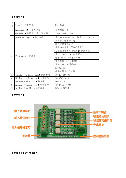
【简要说明】
序
号
Type ♦产品型号GYJ-0153
1.Appearance♦产品外形图参考图在下面
2.Outline ♦外形尺寸长x宽x高72mmX 50mmX 12mm
3.power voltage ♦供电电压输入DC3.3V to 36V 输出DC5V to DC24V
4.Features♦主要特征
具有输入输出指示灯
输入支持高低电平
输出NPN信号(低电平有效)
自带驱动能力可以驱动1W以内负载
输入1.5V to 36V电压可选
输出 5V to 24V电压可选
响应频率0 to 72KHZ
支持72mm DIN导轨壳
5.08mm端子
提供原理图、尺寸图
5.Insulation Resistance♦绝缘电阻100MΩ 500VDC
6.Dielectric Strength ♦介质耐压1000VAC 1min
7.Between Contacts ♦触点间400VAC 1min
8.Ambient Temperature ♦环境温度-30℃ to +70℃
9.Ambient humidity♦环境湿度20% to 80%RH
【标示说明】
【接线说明】NPN信号输入
【接线说明】PNP信号输入
【输入输出可接设备】
【原理图】
【PCB图】
【实物图片展示】
【模块加装壳体效果图】。
北京聚英翱翔电子有限公司 4路继电器板说明书

4路继电器板说明书
------双串口版产品功能及特点
7-30V宽电压供电
RS232、RS485(隔离)双串口通信方式
4路继电器手动控制
支持级联,1-32地址选择
接线方法
实物照片
地址选择:
1、五个拨码全都拨到“ON”位置时,为地址“1”;
2、五个拨码全都拨到“OFF”位置时,为地址“32”;
3、最左边1为二进制最低位。
通信协议
本产品可通过RS485总线,依照标准Modbus协议通信。
Modbus地址为00001-00004对应线圈1-4。
支持功能码1、5、15。
用户使用“16路继电器串口控制软件”或“16路继电器以太网口控制软件”对每一路进行手动控制
软件使用方法
软件界面
将产品通过串口与计算机连接,通过拨码开关设定地址(1-32),在设备地址一栏输入相对应的数值,选择正确串口及串口波特率(4路继电器板为38400,不可更改),点击打开串口,设备即可正常通信。
用户点击需要控制的某一路继电器开关,即可控制相应继电器的开闭。
按钮旁边的指示灯表示当前继电器状态,
常开触点闭合即亮红灯,否则为灰色。
该软件是为16路继电器板定制,所以,只有“继电器1”“继电器2”“继电器3”“继电器4”几个按键可用,5-16号继电器不可用,而且“打开全部”“关
闭全部”也不可用。
四通道充电泵白灯驱动器RGB LED驱动器操作指南(BD1604MUV和BD1604MVV评估板)说

User’s Guide 4-Channel Charge PumpWhite LED Driverwith PWM Brightness ControlBD1604MUV, BD1604MVV Evaluation Board BD1604MUV/MVV-TSB-001 (2.7 V to 5.5 V Input, 120 mA)IntroductionThis user’s guide will provide the necessary steps to operate the Evaluation Boards of ROHM’s BD1604MUV and BD1604MVV LED Drivers. This includes the external parts, operating procedures and application data.DescriptionThis Evaluation Board was developed for ROHM’s 4-Channel Charge Pump White LED Driver with PWM Brightness Control BD1604MUV and BD1604MVV. This LSI is a 4 white LED driver for small LCD backlight. At the charge pump type, the number of external devices is minimized.Application-Recommended Operating ConditionsTable 1. Recommended Operating ConditionsParameter Min Typ Max Units ConditionsInput voltage VBAT 2.7 3.6 5.5VLED maximum current-0.530mA1-ChannelLED current accuracy-0.5 5.0%ILED1-4 = 10mALED current matching-0.5 3.0%ILED1-4 = 10mA (Note 1)LED pin control voltage0.080.100.20V Minimum voltageat LED1 to LED4 pinsISET voltage0.50.60.7V Oscillation frequency0.8 1.0 1.2MHz(Note 1) LED current matching = ((ILEDmax - ILEDmin) / (ILEDmax + ILEDmin)) × 100 ILEDmax: Maximum value of LED1-4 currentILEDmin: Minimum value of LED1-4 current(Note) Unless otherwise specified, above conditions are Ta is 25℃ and VBAT is 3.6V.BD1604MUV BD1604MVVUser’s GuideEvaluation BoardFigure 1. Evaluation Board Top ViewFigure 2. Evaluation Board Bottom ViewISET ResistancePower SourceGNDVBATFlying CapacitorLED4 LED3 LED2 LED1ON/OFF SwitchVOUTSEL1H/L jumperSEL2 H/L jumperEnable jumperSchematicFigure 3. Circuit DiagramParts listNo Value TypeManufacturer CIN 1μF Ceramic Capacitor Murata COUT 1μF Ceramic Capacitor Murata C1 1μF Ceramic Capacitor Murata C2 1μF Ceramic CapacitorMurata C_25 Short - - R2 Open - -RSET 24k Ω,1/10W MCR03 series- LED1 - - - LED2 - - - LED3 - - - LED4 - - - EN_jumper Short - - SELx_H (Note1) Jumper - - SELx_L (Note1)Jumper--(Note1) It is possible to change the number of lightings of LED by terminal setup.Please set up the number of LED lightings by changing the jumper settings of SEL0, SEL1, and SEL2 on the bottom side of the evaluation board. (refer to Fig.2 in P .2). The terminal of the LED, which is not made to turn on, should be shorted to VBAT.Pin ConfigurationFigure 4. Pin Configuration (Top View)Not mountedNot mounted1LED4 1N2N2P23 45 6 7 8 E S E L S E L S E L 12 11 10 9161514 13N DBD1604MUV BD1604MVVSetting for LED LightingStep 1: EN Switch = OFF SettingStep 2: Connect the power supply between VBAT - GNDStep 3: EN Switch = ON Setting➔LED LightingReconstruction1. LED current changingLED current can be changed by resistor value of the ISET terminal.ISET Resistance 165kΩ97.6kΩ48.7kΩ32.4kΩ24.3kΩ16.2kΩILED Current 3mA 5mA 10mA 15mA 20mA 30mA(Note) 24kohm ISET resistor is mounted on the evaluation board. (ILED = 20.25mA/Ch setting)The approximate ILED Current can be calculated by the formula below:ILED Current = 480 / Rset (Rset is the ISET resistance)2. PWM brightness controlWhen using the PWM brightness control by the EN terminal, an evaluation board needs to be converted.Please remove “EN Jumper” (refer to Fig.2 in P.2) on the bottom side of the evaluation board.3. Changing LEDWhite LED is already mounted on the evaluation board. If the user wants to connect a new LED, remove first the LED mounted on the board then connect the new LED.4. Changing LED numberIt is possible to change the number of lightings of LED by terminal setup.Please set up the number of LED lightings by changing the jumper settings of SEL0, SEL1, and SEL2 on the bottom side of the evaluation board. (refer to Fig.2 in P.2). The terminal of the LED, which is not made to turn on, should beshorted to VBAT.ON/OFF controlSEL2 SEL1 SEL0 LED1 LED2 LED3 LED40 0 0 OFF OFF OFF ON0 0 1 OFF OFF ON OFF0 1 0 OFF ON OFF OFF0 1 1 ON OFF OFF OFF1 0 0 OFF OFF ON ON1 0 1 OFF ON ON ON1 1 0 ON ON ON ON1 1 1 OFF OFF OFF OFFNote: 0: 0V, 1: VBATBoard LayoutEvaluation Board PCB informationNumber of Layers Material Board Size Copper Thickness 2FR455mm x 91mm 1.0 oz.BD1604MUV Layout PatternThe layout pattern of BD1604MUV is shown below.Figure 5. Top Layer Layout Figure 6. Bottom Layer Layout (Top View)(Top View)BD1604MUV Evaluation BoardThe Evaluation Board of BD1604MUV is shown below.Figure 7. Evaluation Board Figure 8. Evaluation Board (Top View)(Bottom View)Reference application data (BD1604MUV BD1604MVV)(Evaluation under LED V F = 3.2V)Figure 9. Efficiency Figure 10. Efficiency(5mA × 4 LEDs)(15mA × 4 LEDs)Figure 11. Efficiency Figure 12. LED Current (20mA)(20mA × 4 LEDs) (VBAT=2.7V)Figure 13. LED Current (20mA)Figure 14. LED Current (20mA) (VBAT=3.6V)(VBAT=5.5V)Figure 15. LED Current vs. RSET Figure 16. LED Current vs. PWM Duty (Ta=25℃)(Cycle 100Hz)Other application data refer to datasheet.RESET [kΩ]Revision HistoryDate RevisionNumberDescription1.June.2021001New ReleaseNoticeROHM Customer Support Systemhttps:///contact/Thank you for your accessing to ROHM product informations.More detail product informations and catalogs are available, please contact us.N o t e sThe information contained herein is subject to change without notice.Before you use our Products, please contact our sales representative and verify the latest specifica-tions :Although ROHM is continuously working to improve product reliability and quality, semicon-ductors can break down and malfunction due to various factors.Therefore, in order to prevent personal injury or fire arising from failure, please take safety measures such as complying with the derating characteristics, implementing redundant and fire prevention designs, and utilizing backups and fail-safe procedures. ROHM shall have no responsibility for any damages arising out of the use of our Poducts beyond the rating specified by ROHM.Examples of application circuits, circuit constants and any other information contained herein areprovided only to illustrate the standard usage and operations of the Products. The peripheral conditions must be taken into account when designing circuits for mass production.The technical information specified herein is intended only to show the typical functions of andexamples of application circuits for the Products. ROHM does not grant you, explicitly or implicitly, any license to use or exercise intellectual property or other rights held by ROHM or any other parties. ROHM shall have no responsibility whatsoever for any dispute arising out of the use of such technical information.The Products specified in this document are not designed to be radiation tolerant.For use of our Products in applications requiring a high degree of reliability (as exemplifiedbelow), please contact and consult with a ROHM representative : transportation equipment (i.e. cars, ships, trains), primary communication equipment, traffic lights, fire/crime prevention, safety equipment, medical systems, servers, solar cells, and power transmission systems.Do not use our Products in applications requiring extremely high reliability, such as aerospaceequipment, nuclear power control systems, and submarine repeaters.ROHM shall have no responsibility for any damages or injury arising from non-compliance withthe recommended usage conditions and specifications contained herein.ROHM has used reasonable care to ensur e the accuracy of the information contained in thisdocument. However, ROHM does not warrants that such information is error-free, and ROHM shall have no responsibility for any damages arising from any inaccuracy or misprint of such information.Please use the Products in accordance with any applicable environmental laws and regulations,such as the RoHS Directive. For more details, including RoHS compatibility, please contact a ROHM sales office. ROHM shall have no responsibility for any damages or losses resulting non-compliance with any applicable laws or regulations.W hen providing our Products and technologies contained in this document to other countries,you must abide by the procedures and provisions stipulated in all applicable export laws and regulations, including without limitation the US Export Administration Regulations and the Foreign Exchange and Foreign Trade Act.This document, in part or in whole, may not be reprinted or reproduced without prior consent ofROHM.1) 2)3)4)5)6)7)8)9)10)11)12)13)。
罗宾康说明书5

.
目录
第一章安全注意事项及产品型号.................... 4 1.1 安全注意事项........................................................ 4 1.2 变频器型号说明...................................................... 4 1.3 变频器系列型号...................................................... 4 1.4 产品技术指标及规格.................................................. 5
.
序言
感您选用我公司自主研发的 A600 高性能矢量控制变频器。 A600 高性能矢量控制变频器采用了先进的磁通矢量控制技术, 在对电机参数不敏感的前提下依然实现了高性能的电机控制。它具备 全频高转矩输出及快速响应、极佳的负载适应性、较高的速度控制精 度和良好的可靠性,是真正能够满足较高现场要求的高性能通用变频 器的理想选择。 A600 高性能矢量控制变频器是将客户通用需求与行业性需求有 机结合的产品,为客户提供了实用的 PID 调节器及恒压供水功能、简 易 PLC、可编程的输入输出端子控制、远程同步控制、脉冲频率给定 和其它专用变频器控制等多种强大的功能,为设备制造业和自动化工 程的广大客户提供高集成度的一体化解决方案,对降低系统成本,提 高系统可靠性具有很高的价值。 本手册对用户的设备安装、运行参数的设置、异常诊断、日常维 护及安全使用等具有一定的指导作用。为正确安装及操作本系列产 品,请您在使用 A600 高性能矢量控制变频器之前,务必仔细阅读本 手册。本手册随我们的产品一起发送,请您使用后妥善保管,以备今 后使用。 如果在使用本变频器过程中还有未能解决的疑难问题,请联络本 公司在各地的经销商,或直接与本公司客户服务中心联系。 本公司注重技术创新,如本使用说明书容有变动,恕不另行通知。
GYJ-0150 四路输入输出光电隔离转换模块 光耦电路 电平转换模块 PNP输出型

【简要说明】
序
号
Type ♦产品型号GYJ-0150
1.Appearance♦产品外形图参考图在下面
2.Outline ♦外形尺寸长x宽x高72mmX 50mmX 12mm
3.power voltage ♦供电电压输入DC3.3V to 36V 输出DC5V to DC24V
4.Features♦主要特征
具有输入输出指示灯
输入支持高低电平
输出PNP信号(高电平有效)
自带驱动能力可以驱动1W以内负载
输入1.5V to 36V电压可选
输出 5V to 24V电压可选
响应频率0 to 72KHZ
支持72mm DIN导轨壳
5.08mm端子
提供原理图、尺寸图
5.Insulation Resistance♦绝缘电阻100MΩ 500VDC
6.Dielectric Strength ♦介质耐压1000VAC 1min
7.Between Contacts ♦触点间400VAC 1min
8.Ambient Temperature ♦环境温度-30℃ to +70℃
9.Ambient humidity♦环境湿度20% to 80%RH
【标示说明】
【接线说明】NPN信号输入
【接线说明】PNP信号输入
【输入输出可接设备】
【原理图】
【PCB图】
【实物图片展示】
【模块加装壳体效果图】。
- 1、下载文档前请自行甄别文档内容的完整性,平台不提供额外的编辑、内容补充、找答案等附加服务。
- 2、"仅部分预览"的文档,不可在线预览部分如存在完整性等问题,可反馈申请退款(可完整预览的文档不适用该条件!)。
- 3、如文档侵犯您的权益,请联系客服反馈,我们会尽快为您处理(人工客服工作时间:9:00-18:30)。
GYJ-0040_6路输入输出产品使用说明书【简要说明】一、尺寸:长122mmX宽87mmX高20mm二、主要芯片:单片机STC12C5A60S2 继电器光耦三、工作电压:有直流12V及24V可选。
四、特点:电路结构简单,稳定可靠,采用最新款STC单片机,运行速度快,单片机预留扩展接口。
1、具有6路输入信号指示灯,6路继电器吸合指示灯,电源指示灯。
2、板子功耗小于6W3、额定切换电流10A以内,切换电压250V以内4、单路最大切换功率500W 额定功率300W5、继电器寿命1000000次以上。
6、电器绝缘电阻100M7、触电耐压1000V8、继电器最大吸合时间15mS 毫秒9、继电器最大释放时间5mS 毫秒10、工作温度-40度至+70度11、工作湿度40% ~ 80%RH12、6路光电隔离输入,6路光电隔离输出13、6输入高电平有效(即:PNP输入)14、6路输出开关量输出(即:干接点输出)15、具有MAX232通讯和RS485通讯两种模式可选。
16、单片机有IO口都引出,客户可以自己编程扩展功能17、可以选择使用内部EEPROM 作为存储单元18、电路具有,防反接保护、过流保护、续流保护等19、单片机可以自行更换,可以选择替换型的STC系列单片机20、我们提供电路相关的,原理图、例程、开发环境、下载软件等相关资料适用场合:工业控制、产品开发、项目设计,自动化改造等【标注说明】【接线说明】【输入控制设备】【输出控制设备】【输出举例说明】【输出举例说明】(开关量输出、干接点输出)【串口通信说明】也可以通过串口下载【485通信说明】【扩展接口说明】(我们会在陆续增加、模拟量输入模块、电流模块、电压模块、无线模块、数码管显示模块、液晶模块、按键模块、PWM模块、模拟量输出模块、wifi模块、CAN模块、IP 模块等等。
)【原理图】(提供PDF格式的原理图及PCB图)更清晰免费提供与此工控板有关的:资料、例程、原理图芯片资料、软件。
/********************************************************************实现功能:上、下位机485、232接口控制测试程序上位机编译环境:Vs2008()使用芯片:STC12C5A60S2晶振:11.0592MHZ编译环境:Keil硬件环境:六路输入输出带485和232接口*********************************************************************/ /******************************************************************** 单片机与PC机采用9针串口,MAX232通讯,波特率默认为9600.单片机接收PC机发送的十六进制码表如下:01、全开:PC发送'I';02、全关:PC发送'i';03、第一路开:PC发送'A';04、第二路开:PC发送'B';05、第三路开:PC发送'C';06、第四路开:PC发送'D';07、第三路开:PC发送'E';08、第四路开:PC发送'F';11、第一路关:PC发送'a';12、第二路关:PC发送'b';13、第三路关:PC发送'c';14、第四路关:PC发送'd';15、第三路关:PC发送'e';16、第四路关:PC发送'f';*********************************************************************************************************************************/ #include<STC12C5A60S2.H> //库文件#include <intrins.h>#define uchar unsigned char//宏定义无符号字符型#define uint unsigned int //宏定义无符号整型/********************************************************************初始定义*********************************************************************/unsigned char dat; //用于存储单片机接收发送缓冲寄存器SBUF里面的内容/*定义八位数字量输入为单片机P0口*/sbit X00=P1^0;sbit X01=P1^1;sbit X02=P1^4;sbit X03=P1^5;sbit X04=P1^6;sbit X05=P1^7;/*定义八位数字量输出IO口*/sbit Y00=P2^0;sbit Y01=P2^1;sbit Y02=P2^2;sbit Y03=P2^3;sbit Y04=P2^4;sbit Y05=P2^5;/********************************************************************延时函数*********************************************************************/ void delay(uchar t){uchar i,j;for(i=0;i<t;i++){for(j=250;j>0;j--);{ ;}}}/********************************************************************输出处理函数*********************************************************************/ void open_X3(uchar turm){char i;for(i=7;i>=0;i--){turm=_crol_(turm,1);switch(i){case 0:Y00=turm&0x01;break;case 1:Y01=turm&0x01;break;case 2:Y02=turm&0x01;break;case 3:Y03=turm&0x01;break;case 4:Y04=turm&0x01;break;case 5:Y05=turm&0x01;break;default:break;}}}/******************************************************************** 功能:串口初始化,波特率9600,方式1*********************************************************************/ void Init_Com(void){//串口初始化TMOD = 0x20;SCON = 0x50;TH1 = 0xFd;TL1 = 0xFd;TR1 = 1;ES=1; //开串口1中断//485接口初始化S2CON=0x50; //方式1,八位数据,可变波特率AUXR1=0x00; //1T工作方式BRT=0XFD; //设置波特率9600AUXR=0x10; //启动波特率发生器EA=1; //开总中断IE2=0x01; //开串口2中断}/********************************************************************配置P4口*********************************************************************/ void P4_init(void){P4SW=0x70; //配置P4口P4M0&=0x80;P4M1&=0x80;}/********************************************************************配置P4口*********************************************************************/ void B485_send(uchar c){SBUF=S2BUF=c;}/********************************************************************主函数*********************************************************************/ void main(){Init_Com();//串口初始化P4_init();while(1){if(X00==0) {delay(20);Y00=0;while(!X00);Y00=1;B485_send(0XA1);} if(X01==0) {delay(20);Y01=0;while(!X01);Y01=1;B485_send(0XA2);}if(X02==0) {delay(20);Y02=0;while(!X02);Y02=1;B485_send(0XA3);}if(X03==0) {delay(20);Y03=0;while(!X03);Y03=1;B485_send(0XA4);}if(X04==0) {delay(20);Y04=0;while(!X04);Y04=1;B485_send(0XA5);}if(X05==0) {delay(20);Y05=0;while(!X05);Y05=1;B485_send(0XA6);} switch(dat) //接收数据判断{uchar k;k=10;case 'I': open_X3(0x00);delay(k);break; // 全开case 'i': open_X3(0xff);delay(k);break; // 全关case 'A': Y00=0;delay(k);break; // 第一路开case 'B': Y01=0;delay(k);break; // 第二路开case 'C': Y02=0;delay(k);break; // 第三路开case 'D': Y03=0;delay(k);break; // 第四路开case 'E': Y04=0;delay(k);break; // 第五路开case 'F': Y05=0;delay(k);break; // 第六路开case 'a': Y00=1;delay(k);break; // 第一路关case 'b': Y01=1;delay(k);break; // 第二路关case 'c': Y02=1;delay(k);break; // 第三路关case 'd': Y03=1;delay(k);break; // 第四路关case 'e': Y04=1;delay(k);break; // 第五路关case 'f': Y05=1;delay(k);break; // 第六路关default:break; // 跳出}}}/********************************************************************串口中断函数*********************************************************************/ void commIntProc() interrupt 4{if(TI)TI = 0;if(RI){RI = 0;dat = SBUF;} //接收数据SBUF赋与dat}/********************************************************************串口二(485) 发送接收中断函数*********************************************************************/ void uart2_isr() interrupt 8{if( S2CON & 0x01 ){S2CON &= ~0x01;dat= S2BUF;}if( S2CON & 0x02 ){S2CON&=0xfd;}}/********************************************************************结束*********************************************************************/ 【尺寸图】以下图纸仅供参考,具体请以实物为准【图片展示】【加装配套外壳效果】。
