Orcaflex 基础介绍
Flex技术基础培训

Flex Builder2 消息服务 数据管理服务 RPC服务 消息服务
Flex Data Services2 消息服务 数据管理服务 RPC服务
15
2014年11月21日星期五
Flex 基本架构
Flex Data Services
RPC服务 消息服务
Flex Charting
可扩展图形组件
Flash Builder4
通过设置组件属性改变其外观
图形资源 数据
2014年11月21日星期五
21
MXML基本语法
MXML是遵循W3C XML标准的标记语言。 MXML中融合了众多的标准。
1.XML标准 2.DOM Level 3事件模型标准
3.Web服务标准
5.HTTP标准 7.CSS标准
Flex 基本架构
Flex的基本架构包括4部分
1.Adobe SDK
2.Adobe Flex Charting 3.Adobe Flex Data Services 4.Adobe Flex Builder
Flex SDK2 MXML ActionScript3.0 Flex框架和类库 命令行编译与调试 Flex Charting2 可扩展图形组件
Flex技术基础培训
二零壹二年
Flex 简介
Flex通常是指Adobe Flex,是最初由Macromedia公司在2004年3 月发布的,基于其专有的Macromedia Flash平台,它是涵盖了支 持RIA(Rich Internet Applications)的开发和部署的一系列技 术组合。 2004年 Micromedia发布Flex1.0 2005年 Adobe兼并Micromedia 2006年Adobe发布Flex2.0 2008年Adobe发布Flex3.0 2010年Adobe发布Flex4.0 2011年Adobe发布Flex4.5
Flex从入门到精通_第6章

6.2.3 改变按钮外观
• • • • • 如果按钮控件是激活状态,它就可以有下列行为: 当鼠标指向按钮,按钮控件显示rollover状态。 当鼠标点击按钮,按钮控件显示按下(pressed)状态。 如果鼠标移出按钮区域,按钮控件恢复其原始状态。 如果按钮控件禁用状态,就显示为禁用外观,并对所有用 户行为不产生响应。在Flex中,可以有不同的图像来对应 不同的外观属性,每个属性对应不同的按钮状态。 上(Up):鼠标不在按钮上,也就是按钮的原状。 下(Down):鼠标按下按钮。 上方(Over):鼠标指在按钮上。 禁用(Disabled):按钮处在禁用状态。
6.1.6 控件定位(Positioning Control)
• 控件放置在容器中时,将其放置在什么位置,就是对控件 的定位。通过对控件的定位,可以调整页面布局。当编程 者将控件放置在容器内,多数容器可以自动确定子类的位 置。画布(Canvas)容器对子类进行绝对值定位。应用 (Application)容器、面板(Panel)容器可选择绝对值 定位或相对值定位。 • 对控件的绝对值定位,就是设定其x、y坐标属性,即定义 在容器中水平和垂直像素坐标。这里,坐标原点(0,0)就 是容器的左上角。在面板容器中,添加了一个按钮控件。 按钮的位置定义为距离面板左上角横坐标20像素,纵坐标 20像素的位置。
6.7 链接按钮控件(LinkButton Control) • 链接按钮控件是一个单行的文本超链接,类似与 HTML的超链接<a href=””>。单击文本链接就可 以打开一个新的浏览器窗口或进行某个操作。
6.7.1 链接按钮控件概述
• 在MXML中,使用<mx:LinkButton>标签来定义链接 按钮控件。链接按钮控件不仅可以是文本的链接, 也可以是使用图标做链接当鼠标在链接按钮上时, 链接按钮颜色变化的效果。
FLEX快速入门介绍

Flex快速入门介绍一、Flex简介:Flex是一个针对企业级富互联网应用的表示层解决方案,是一种应用程序框架。
Flex系列产品包括编译工具和IDE,通过编写MXML和ActionScript代码,用编译器来生成swf文件,使用浏览器的Flash Player插件就可以进行观看。
MXML代码与jsp 很像,主要是用于布局和显示,ActionScript代码和javascript很像,语法也有很多相似之处。
总的来说,使用java的程序员很容易入手学习flex。
二、Flex与ActionScript基础:一个Flex应用程序有ActionScript和MXML两种语言代码组成。
从3.0开始ActionScript已经从基于原型脚本语言进化到完全面向对象的。
MXML则是一种标记语言,非常类似于大家所熟悉的超文本标记语言(HTML),扩展标记语言(XML)。
如何把MXML和ActionScript相互关联起来呢?对于编译器来说,解析这两种语法后最终被翻译成同一个对象,比如:<mx:Button id="btn"label="My Button"height="100"/>和Var btn:Button=new Button();bel="MyButton";btn.height=100;产生的是同一个对象,两者的主要不同是,ActionScript创建的对象(上面第二个例子)除了Button就没有别的了,而MXML中创建的对象将Button添加到包含MXML代码的任何组件上。
Flex框架根据MXML中的对象描述来调用构造函数,然后将其添加到父对象上或设置其为父对象的某个属性。
MXML文件中可用<mx:Script>标签包含ActionScript,不过ActionScript文件是不能包含在MXML里的。
Flex从入门到精通 第7章

7.1.3 Flex的分类
Flex容器按其使用方式又可分为两类:布局 (Layout)和导航(Navigator)。 1.布局容器(Layout Container) 这类容器用于对子类组件定位和限定尺寸。 2.导航容器(Navigator Container) 这类容器用于控制用户的对多个子类容器的导航、 转移。
7.4.3 折叠导航容器(Accordion navigator Container)
在MXML中,使用<mx: Accordion > 标签定义折叠导航容器。折叠导航容 器建立一系列的面板,依次叠加起来。每个面板的头就是它的导航按钮。 点击任何一个按钮就会打开相应的面板。折叠导航容器有一个非常好的应 用实例。在HTML网页中,购物往往需要几个页面来完成。用户填写完一个 页面,提交之后,再填写下一个页面,直到完成。折叠导航容器,可以将 几个页面分置在其几个单独面板中,填写完成后,统一提交。也可以在不 同的面板分置不同种类的商品目录。 在折叠容器中,每个层面只能容纳一个子类,其语法句式如下: <mx:Accordion 属性 样式 事件 > 子类标签 </mx:Accordion >
7.4 导航容器(Navigator Container)
导航容器是用来控制一组子类容器的移动,导航。 导航容器只定义子类容器的顺序,不定义子类容 器的布局和定位。导航容器中的子类,必须是容 器,而不是控件组件。 Flex提供了以下的导航容器: 视窗堆栈导航容器 标题头导航容器 折叠导航容器
7.3.2 盒子,水平盒子,垂直盒子布局容器(Box, HBox, VBox Layout Container)
盒子容器的是在水平或垂直方向上按序排列子类 组件。其语法句式如下: <mx:Box 属性 样式 > 子类标签 </mx:Box>
Orcaflex 基础介绍

Line 定义
Connection ( End A & End B)
End connection End position End orientation End release
Connection stiffness
单击此处编辑副标题
-设计公司
二零一四年十一月
海洋石油工程股份有限公司
第一部分:软件整体介绍 第二部分:分析流程介绍
第三部分:分析实例
2
Orcina公司简介
模型单元 (link、winch、shape) 环境参数
Orcaflex软件介绍
软件主界面 建模常规流程介绍
模型单元(line)
环境参数(seabed)
1 Shape Flat Profile 3D 2 Seabed Origin 3 Stiffness & Damping
P22
环境参数(wave)
Wave Type Single airy Stokes’ 5th Spectrum Time history ……
Direction Height Period
P23
环境参数(wind)
Wind Type Constant Spectrum Time history Direction Speed
P24
环境参数(current) Current Data Direction Speed Profile Depth Factor rotation
P11
Line 定义
Statics
Catenary Spline Quick Prescribed User specified
Flex 3 基础教程(1)
Flex 3 基础教程(1) 基础教程(1
——简介,安装和开发环境 ——简介,安装和开发环境
郑岩峰 20082008-5-18
Adobe Flex 3 简介 什么是Adobe Flex? 什么是Adobe Flex? Flex Builder 3 教程 使用Flex 使用Flex Builder 设计视图 Hello World应用程序 World应用程序 程序结构解析
如何创建Flex 如何创建Flex应用程序 Flex应用程序 步骤如下: 选取预定义的可视化组件 在用户界面上添加组件 使用styles和skins自定义应用程序界面 使用styles和skins自定义应用程序界面 增加事件处理和脚本处理代码,控制应用 程序行为 连接数据和通讯服务 Build和Run应用程序 Build和Run应用程序
什么是Flex 什么是Flex 3
Flex 3是Adobe出品的开发RIA(Rich Internet 3是Adobe出品的开发RIA(Rich Applications)的工具,包括: Applications)的工具,包括: Flex 3 SDK(软件开发包) SDK(软件开发包) -Compiler (编译器) (编译器) -Framework (Flex类库) (Flex类库) -Debugging tools (调试工具) (调试工具) Flex Builder 3 -整合和开发环境 -基于eclipse 基于eclipse 和Flex整合的服务器产品 Flex整合的服务器产品 -LiveCycle Data Services 2.51 -ColdFusion 8
Flex技术之一基础培训精品PPT课件

在web工程中建立Flex应用
4、点击finish之后,web工程结构如下图:
Flex应用说明
1、使用: mxml是flex builder可视化工具生成的。 但实际使用的不是.mxml文件,而是flex builder编 译器对.mxml进行编译生成的.swf文件;相当于java 的类,编写的是.java文件,实际使用的是.class。
<?xml version="1.0" encoding="utf-8"?> <mx:Application xmlns:mx="" layout="absolute"> <mx:Button label="hello world“ /> </mx:Application>
Flex应用程序的编译和发布
Flex应用程序
开发Flex应用程序的步骤
开发Flex应用程序的典型步骤如下(通常是这样) : 1. 选取一系列预先定制好的、用于设计应用程序
界面的组件(如表格、按钮等等) 2. 布置组件以设计用户界面。 3. 使用样式和主题来增强视觉方面的设计。 4. 添加动态行为(例如程序部件之间的相互作用) 。 5. 定义并连接所需的数据库服务。 6. 将源代码编译成SWF文件,然后在 Flash Player 中
AJAX(异步JavaScript和XML)轻量级
Silverlight(WPF/E)基于.net
重量级
FLEX (XML AS3)
三个最
3.什么是FLEX技术?
是Adobe公司推出的一系列框架和技术,使开发人员 可以开发和部署RIA程序(flash程序)。
第1章 Flex概述

Flex 4.0 RIA开发详解 第2版) 开发详解(第 版 开发详解
1.1
Flex简介 Flex简介
Adobe公司对于 公司对于Flex采取了开源的策略,所以开发者可 采取了开源的策略, 公司对于 采取了开源的策略 以在Flex原代码的基础上修改.新版Flex 4中的开发环境已 以在 原代码的基础上修改.新版 中的开发环境已 原代码的基础上修改 经更名为Flash Builder,而不再是Flex Builder系列 Flex采 系列. 经更名为Flash Builder,而不再是Flex Builder系列.Flex采 用事件驱动机制, 用事件驱动机制,程序的执行过程严格按照事件发生的时间 顺序执行.本节将介绍为读者Flex开发技术的特点,优点和 开发技术的特点, 顺序执行.本节将介绍为读者 开发技术的特点 新特性. 新特性.
Flex 4.0 RIA开发详解 第2版) 开发详解(第 版 开发详解
Flex的技术特点 1.1.1 Flex的技术特点
Flex可以在企业内部或在 Web 上创建富互联网应用程 可以在企业内部或在 ),堪称最完整 开发解决方案. 序(RIA),堪称最完整,最强大的 ),堪称最完整,最强大的RIA开发解决方案.它 开发解决方案 使企业能够创建个性化的丰富多媒体应用程序, 使企业能够创建个性化的丰富多媒体应用程序,极大地提高 用户的体验, 的交互关系. 用户的体验,彻底革新人与 Web 的交互关系. 1.增强用户体验 . 2.完善的开发环境 . 3.通用的配置环境 . 4.企业级的特征 . 5.消除页面加载 . 6.标准的架构 . 7.与浏览器兼容 .
Flex 4.0 RIA开发详解 第2版) 开发详解(第 版 开发详解
1.4
建立第一个Flex 4程序 建立第一个Flex 4程序
Orcaflex基础介绍

模型单元(winch)
主要用于模拟绞车,提供持续的拉力或恒 定的牵引速度
模型单元(Winch)
Connection Winch Wire Control
模型单元(shape)
简单的三维几何形状,可用于模拟障碍物 、月池或者仅作为图形示意
模型单元(Shape)
Connection Type Geometry Stiffness & damping
✓ Software licensing rather than dongles.
主要特点及优势
软件易用性:
海洋工程细长结构物动力计算分析+环境载荷
多任务、批处理、分析能力高效
便利、直观、高质量的图形用户界面,可以简单、快速的建立模型 使用功能:
✓ 系统图像显示可选线框或者三维实体显示 ✓ 可选择隐式或显式的积分迭代法 ✓ 浮体与线杆结构的耦合分析 ✓ 分析模型可包括风、浪、流等环境参数 ✓ 可建立各种海底条件,包括平整海底面,二维海底及三维海底 ✓ 可用第三方软件如:Excel, Text file, Python, Matlab进行批处理操作 ✓ 可进行干涉分析、疲劳分析(包括VIV分析)、模态分析
OrcaFlex 9.1
Aug-07
OrcaFlex 9.0
Sep-06
OrcaFlex 8.7
Nov-05
OrcaFlex 8.6
Feb-05
OrcaFlex 8.5
Jun-04
OrcaFlex 8.4
Dec-03
OrcaFlex 8.3
Jul-03
OrcaFlex 8.2
Dec-02
OrcaFlex 8.1
谢谢!
计算软件Offpipe和Orcaflex应用于海底管道S型铺设分析的比较研究
计 算软件 O 邱i p e 和O r c a l f e x应用 于海底管道
S型铺设分析 的 比较研 究
王 波
( 海洋 石油工程股份 有限公司,天 津 3 0 0 4 5 1 )
摘
要
用软件O f i p e 进行 海底管道s 型正 常铺设 时的静 态分析 ,并 以此为基 础,将它与软件O r c a f l e x N相应结 果进行 对 比。结果表 明,尽管O r c a l f e x 没有提供 完整 的适用 于s 型铺管模拟 的模型 ,但是借 助于其 灵活的建 模功 能, 仍 然可 以获得相 当合理的分析结果。相 比于0 饰i p e , 0 r c a n e x 更加适用于进行海底管 道铺 设动态分
由A &R绞 车 ( A &RWi n c h ) 、张紧 器 ( T e n s i o n e r ) 、托 管架 ( S t i n g e r )和 管道 支 撑滚 轮 ( R o l l e r )
等 组 成 ,如 图 1所 示 。S型铺 设 法 的显 著优 点是 铺管 效 率 高 ,缺 点是 由于管 道悬 空段较 长 ,铺 管 系 统 需 要 维持 非 常 大 的张力 ,这给 铺 管 船动 力 定位 系 统和 张 紧器 等 提 出 了很 高 的要 求 。此 外 ,由于使
5 4卷 增刊 2 2 0 1 3年 1 1 月
中 国 造 船 S HI P BU I L DI NG OFC HI NA
Vo 1 . 5 4 Sp e c i a l 2 NOV . 20 1 3
文章编号 :1 0 0 0 - 4 8 8 2 ( 2 0 1 3 ) ¥ 2 . 0 1 0 7 . 0 7来自 1 0 8 中
国
学习Flex首先要了解RIA技术RIA是企
学习Flex首先要了解RIA技术RIA是企第章Flex概述Adobe® Flex™是Adobe公司推出的多平台的RIA(Rich Internet Applications)开发产品。
它包含了一系列技术与产品,如Flex Framework、Flex Builder、Flex Charting、Adobe LiveCycle Data Services ES等。
本章将全面介绍Flex与Flex技术;对比Flex应用与传统网页应用;学习Flex包含的各个元素,与它们的工作原理。
1.1 RIA概述学习Flex首先要熟悉RIA技术。
RIA(富互联网应用程序)是企业级应用程序客户端的最新技术,具有高度的用户互动性与丰富的用户体验。
RIA技术的出现是在企业级应用程序经历了几次系统构架方面的转变的必定结果。
企业级应用程序最初的模式是客户机/服务器(Client/Server,C/S)应用程序。
20世纪90年代随着Windows的出现与客户端处理能力的增强,出现了客户机/服务器应用程序。
它使用图形用户界面,客户端的数据处理能力比较强。
但由于受到使用局域网的限制,客户端应用程序需要进行不断的更新,因此其应用范围存在很大的局限性。
20世纪90年代中期,互联网飞速进展,出现了浏览器/服务器(Browser/Server,B/S)应用程序。
Web技术的使用解决了C/S应用程序问题,但由于使用了HTML页面形式的用户界面,客户端的数据处理能力较C/S应用程序有所减弱。
RIA技术的出现重新平衡了客户端与服务器端的关系。
RIA是B/S技术在客户端的突破进展,它是集桌面应用程序的最佳用户界面功能与Web应用程序的普遍使用与快速、低成本布署与互动多媒体通信的实时快捷于一体的新一代网络应用程序。
RIA大致包含了Flex、Ajax、WPF、OpenLaszlo与Google Web Toolkit等一系列产品,而Flex是同类产品中最领先与成熟的产品,改善了用户体验。
OrcaFlex软件操作指南
OrcaFlex软件操作指南OrcaFlex软件操作指南按照客户要求,本报告以钢悬链立管(SCR)为例,从SCR总体强度分析、运动疲劳分析和安装分析三个方面给出了OrcaFlex软件的主要操作指南,现分别叙述如下。
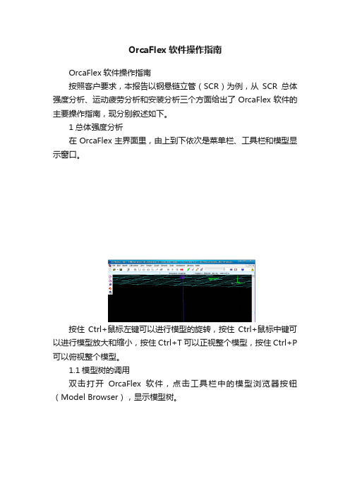
1总体强度分析在OrcaFlex主界面里,由上到下依次是菜单栏、工具栏和模型显示窗口。
按住Ctrl+鼠标左键可以进行模型的旋转,按住Ctrl+鼠标中键可以进行模型放大和缩小,按住Ctrl+T可以正视整个模型,按住Ctrl+P 可以俯视整个模型。
1.1模型树的调用双击打开OrcaFlex软件,点击工具栏中的模型浏览器按钮(Model Browser),显示模型树。
1.2环境参数设置 双击Environment 按钮打开环境参数设置界面。
1.2.1Sea由上到下可依次设置海平面位置,运动粘性系数,海水温度,雷诺数计算方法,具体如下面表格所示。
其中海平面位置数值是相对于总体坐标系而言;温度为摄氏温度,它的大小直接影响到运动粘性系数。
而雷诺数的计算方法,主要取决于流速和结构特征长度的计算。
软件中三种方法雷诺数最终的计算公式分别为Re nom= |Vr|D/ν,Re cross = |Vr|Dcos(α)/ν,Re flow= |Vr|D/νcos(α),其中Vr径向速度。
OrcaFlex calculates Reynolds number in order to calculate drag and lift coefficients1.2.2Sea Density设置海水密度,可以是变化的,也可以是恒定不变的。
如该海域的海水密度为1025Kg/m3,具体如下图所示。
1.2.3Sea Bed设置海底形状,海水的深度、斜度以及海底土壤的刚度系数,其中海底斜度和海底方向都是相对于总体坐标系而言,具体参数应在立管总体设计参数中给1.2.4Waves设置波浪的参数,主要包括波浪方向、波高、周期、起始时间,波浪类型等,其中波浪方向是相对于总体坐标系而言,波浪类型的选取取决于分析类型和实际海况,波高和周期根据海况资料给出,具体参数设置如下面表格和图所示。
Orcaflex基础介绍 ppt课件

主要特点及优势
软件易用性:
海洋工程细长结构物动力计算分析+环境载荷
多任务、批处理、分析能力高效
便利、直观、高质量的图形用户界面,可以简单、快速的建立模型 使用功能:
✓ 系统图像显示可选线框或者三维实体显示 ✓ 可选择隐式或显式的积分迭代法 ✓ 浮体与线杆结构的耦合分析 ✓ 分析模型可包括风、浪、流等环境参数 ✓ 可建立各种海底条件,包括平整海底面,二维海底及三维海底 ✓ 可用第三方软件如:Excel, Text file, Python, Matlab进行批处理操作 ✓ 可进行干涉分析、疲劳分析(包括VIV分析)、模态分析
P12
Line 定义
Structure Attachment
P13
模型单元(Link)
本身不具备质量和水动力属性,用于连接 任意的两个点,并传递拉力/压力,常用于 模拟钢丝绳
模型单元(Link)
Type
Tether Spring/Damper
模型单元(Link)
Connection Release Drawing Stiffness
P3
企业背景
成立于1986年,公司位于英国Ulverston,主要提供海洋工程结构及水 动力项目咨询
目前致力于软件开发工作
数学专业人员,软件开发人员, 机械、力学专业人员及海洋工程技术 人员
OrcaFlex是一款世界领先的动力学分析计算的海洋工程软件包,主要应用于: 海洋工程学 地震防御 海洋工学 海洋学研究 水产业
Sep-02
OrcaFlex 8.0
Maylease 9.8a
9.7d 9.6c 9.5d 9.4g 9.3c 9.2f 9.1e 9.0g 8.7d 8.6d 8.5d 8.4e 8.3d 8.2c 8.1b 8.0e
OrcaFlex软件操作的指南

OrcaFlex软件操作指南按照客户要求,本报告以钢悬链立管(SCR)为例,从SCR总体强度分析、运动疲劳分析和安装分析三个方面给出了OrcaFlex软件的主要操作指南,现分别叙述如下。
1总体强度分析在OrcaFlex主界面里,由上到下依次是菜单栏、工具栏和模型显示窗口。
按住Ctrl+鼠标左键可以进行模型的旋转,按住Ctrl+鼠标中键可以进行模型放大和缩小,按住Ctrl+T可以正视整个模型,按住Ctrl+P可以俯视整个模型。
1.1模型树的调用双击打开OrcaFlex软件,点击工具栏中的模型浏览器按钮(Model Browser),显示模型树。
1.2环境参数设置双击Environment按钮打开环境参数设置界面。
1.2.1Sea由上到下可依次设置海平面位置,运动粘性系数,海水温度,雷诺数计算运动粘性系数海水温度(o T)雷诺数计算方法水平面位置(m)(m2/s)0 1.2E-6 15 沿横流方向计算其中海平面位置数值是相对于总体坐标系而言;温度为摄氏温度,它的大小直接影响到运动粘性系数。
而雷诺数的计算方法,主要取决于流速和结构特征长度的计算。
软件中三种方法雷诺数最终的计算公式分别为Re nom= |Vr|D/ν,Re cross= |Vr|Dcos(α)/ν,Re flow= |Vr|D/νcos(α),其中Vr径向速度。
OrcaFlex calculates Reynolds number in order to calculate drag and lift coefficients1.2.2Sea Density设置海水密度,可以是变化的,也可以是恒定不变的。
如该海域的海水密度为1025Kg/m3,具体如下图所示。
1.2.3Sea Bed设置海底形状,海水的深度、斜度以及海底土壤的刚度系数,其中海底斜度和海底方向都是相对于总体坐标系而言,具体参数应在立管总体设计参数中给出。
具体如下面表格和图表所示。
flex技术介绍

MXMLC 编译器
•MXML to AS 3 •CSS to AS 3 •AS 3 to ByteCode •Assets to SWF •ByteCode to SWF •SWF 运行于 Flash Player 9
Flex可视化组件
• • • • • • • • • • Flex可视化组件指的是Flex内置的图形组件,用于在Flex应用的开发过程中,灵活的 构建用户可视化图形界面。主要包括以下3种。 控件(Controls):按钮、组合框等。 容器(Containers):存放控件的地方。当然,它也可以存放容器。 图表(Charting):利用X、Y轴组成的二维图形表达数据。 对于上述组件来来说,他们有如下几个共同的特征: 尺寸(Size):每一种控件都有自己默认的尺寸。在使用这些控件的时候,可以使用默 认尺寸,也可以根据需求改变,还可以在应用运行时,动态改变。 事件(Event):用户界面的元素,需要对用户的操作做出反应,这就是事件,例如: 单击按钮,在运行时动态创建组件等,事件是组件非常重要的组成部分。 样式(Style):样式是用来显示组件的元件。在Flex中可以利用样式表(CSS, Cascading Style Sheets),设定组件的样式。 行为(Behaviors):由用户或者应用触发,改变组件的状态。例如,用户使用鼠标拖 放组件。 皮肤(Skin):组件的外观。
RIA技术概述
•RIA是Rich Internet Applications的缩写, 翻译为丰富互联网应用程序。RIA的目标是将 桌面程序的表现力与浏览器的程序的方便、快 捷结合在一起。开发者可以在浏览器程序上部 署C/S客户端的程序,得到比传统HTML更强大 的表现力。
RIA的特点
•RIA最突出的特点为“Rich”,同时RIA最核心的部分也体现 在“Rich”中。“Rich”包含了两层含义: •1.丰富的数据模型 •RIA技术提供了多种数据模型来处理客户端复杂的数据操作。 使用RIA可以将部分原本需要在后台程序处理的问题转移到客 户端,使数据能够被缓存在客户端,从而可以实现一个比基 于HTML的响应速度更快,且数据往返于服务器的次数更少的 用户界面。 •2.丰富的界面元素 •RIA技术提供了比HTML更为丰富的界面表现元素,密集、响 应速度快和图形丰富的页面元素与数据模型结合在一起,为 用户提供好的使用体验。
ORACLE ERP开发之OracleForms基础
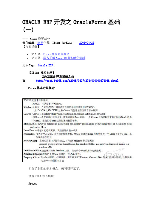
ORACLE ERP开发之OracleForms基础(一)—— Forms设置部分责任编辑:晓熊作者:IT168 JarWang2009-04-28【内容导航】∙第1页:Forms基本对象概念∙第2页:深入了解Forms的事务触发机制文本Tag:Oracle ERP【IT168 技术文档】ORACLEERP开发基础之前言/a2009/0427/274/000000274048.shtml Forms基本对象概念明白了上面的基本概念,就可以开工了。
设置ITEM为必填项Setup:Effect:此效果与是set_item_property('test.l_test',required,property_true)一样的。
设置ITEM的初始值为当前日期实现按“ENTER”自动跳至下一条记录设置BLOCK属性:导航器风格:改变记录。
使用堆叠画布Effect:1. 先将数据块、画布布局好(用向导的方式就可以了,具体操作就不用讲了吧)。
2. 在画布中创建一个堆叠画布。
3. 将项的画出属性更为堆叠画布(这一步最关键了)。
4.调整后得到下面这效果了。
深入了解Forms的事务触发机制编写一个健壮的FORMS应用程序,免不了要做各种数据的检验动作。
所以必须了解FORMS事务触发器的工作原理。
其他类型的触发器相对来说比较好理解,就不详说了。
① FORMS处理事务分成发送(POST)和提交(COMMIT)两个阶段。
这个跟JAVA 中的事务操作类似,也就是Statement和Commit两个阶段。
但FORMS一些规则比较死,也就是说规定好POST之前会触发PRE触发器之类等等。
②事务触发器分成三类,PRE-XXX、ON-XXX、POST-XXX,它们的执行顺序可以直接从其英文缩写得出。
例:执行INSERT操作,会按以下顺序进行。
1.1从数据项复制数据。
1.2触发PER-INSERT触发器。
1.3检查记录的惟一性。
FAST v8 OrcaFlexInterface 用户指南说明书

User’s Guide to using OrcaFlexInterface in FAST v8 IntroductionThis document briefly describes how to use OrcaFlex coupled to FAST v8 for modeling floating offshore wind turbines. OrcaFlex is a commercial software package developed by Orcina for the design and analysis of marine systems. When the OrcaFlexInterface module is used in FAST, all hydrodynamic and mooring loads will be computed using OrcaFlex, while the turbine, tower, and floating platform structural dynamics; aerodynamics; and control and electrical-drive dynamics will be computed by FAST. To use this module with FAST, a valid OrcaFlex license is needed and a special DLL compiled by Orcina is required (FASTlinkDLL.dll). This DLL is called by FAST during the FAST simulation to compute the loads on the platform by OrcaFlex. A 32- and 64-bit version of FASTlinkDLL.dll compatible with the 32- and 64-bit Windows executable version of FAST is available at /Support/FASTlink.zip. One should choose the version that matches the addressing scheme of the version of OrcaFlex that is installed, otherwise the simulation will not run. A 32- and 64-bit Windows executable version of FAST v8 is available at https:///FAST8.At this time, FAST’s ElastoDyn structural-dynamics module assumes for a floating platform that the substructure (floating platform) is a six degree-of-freedom (DOF) rigid body. At each time step (the FAST glue code and OrcaFlex must both use the same time step), OrcaFlex receives the six-DOF position, orientation, and velocities of the platform, computes the hydrodynamic and mooring loads, and returns them back to FAST in the form of a six-by-six added-mass matrix and six-by-one load vector (three forces and three moments). FAST will take these OrcaFlex outputs, along with the six-DOF platform acceleration, and compute the total six-component hydrodynamic and mooring loads to be applied to the platform in ElastoDyn, including hydrodynamic added-mass effects.This document was written when the interface between OrcaFlex 9.8d and FAST v8.12 was first developed, but may apply to newer releases. It may also work with earlier versions of OrcaFlex, starting with 9.7b, though compatibility has not been tested.Modifying the FAST Input FileWhen the OrcaFlexInterface module is used in FAST, all hydrodynamic and mooring loads will be computed using OrcaFlex. This replaces the HydroDyn module and alternative mooring modules. In the FAST input file, this is done by setting the following options in the FAST primary input file: •CompHydro = 0•CompMooring = 4•MooringFile = “<OrcaIptFileName>”where <OrcaIptFileName> is the name of the input file for the OrcaFlexInterface module. The format of this file is as given in Appendix A. This file specifies the name of the OrcaFlex input file without the .dat file extension (OrcaIptFileName) and the name of the Windows DLL supplied by Orcina with the .dll file extension (DLL_FileName).As OrcaFlex and the FAST glue code must both use the same time step, an appropriate time step suitable to both software should be selected. Additionally, the six platform DOFs in FAST’s ElastoDyn module should also be enabled to properly transfer loads and motions between FAST and OrcaFlex. Also, the same platform initial conditions should be set in both ElastoDyn and OrcaFlex.No other changes are required or limitations imposed on FAST.FAST Output VariablesWhen FAST is executed with the OrcaFlexInterface module enabled, an additional 18 output channels are automatically added to the FAST output file (see Table 1). Additional results calculated internally within OrcaFlex are written to the OrcaFlex simulation file, <OrcaIptFileName>.sim, accessible through OrcaFlex.Table 1: Output Parameters from OrcaFlexInterfaceName Description Convention UnitsDirected along x i-axis (kN) OrcaFxi Total platform horizontal surge force (includingadded mass)Directed along y i-axis (kN) OrcaFyi Total platform horizontal sway force (includingadded mass)Directed along z i-axis (kN) OrcaFzi Total platform vertical heave force (including addedmass)About the x i-axis (kN·m) OrcaMxi Total platform roll tilt moment (including addedmass)About the y i-axis (kN·m) OrcaMyi Total platform pitch tilt moment (including addedmass)OrcaMzi Total platform yaw moment (including added mass) About the z i-axis (kN·m)Directed along x i-axis (kN) OrcaHMFxi Platform horizontal surge force calculated byOrcaFlex (hydrodynamic + mooring)Directed along y i-axis (kN) OrcaHMFyi Platform horizontal sway force calculated byOrcaFlex (hydrodynamic + mooring)Directed along z i-axis (kN) OrcaHMFzi Platform vertical heave force calculated by OrcaFlex(hydrodynamic + mooring)About the x i-axis (kN·m) OrcaHMMxi Platform horizontal roll tilt moment calculated byOrcaFlex (hydrodynamic + mooring)About the y i-axis (kN·m) OrcaHMMyi Platform horizontal pitch tilt moment calculated byOrcaFlex (hydrodynamic + mooring)About the z i-axis (kN·m) OrcaHMMzi Platform horizontal yaw moment calculated byOrcaFlex (hydrodynamic + mooring)Directed along x i-axis (kN) OrcaAMFxi Platform horizontal surge force due to added masseffectsDirected along y i-axis (kN) OrcaAMFyi Platform horizontal sway force due to added masseffectsDirected along z i-axis (kN) OrcaAMFzi Platform vertical heave force due to added masseffectsOrcaAMMxi Platform horizontal pitch roll moment due to added About the x i-axis (kN·m)mass effectsAbout the y i-axis (kN·m) OrcaAMMyi Platform horizontal pitch tilt moment due to addedmass effectsAbout the z i-axis (kN·m) OrcaAMMzi Platform horizontal yaw moment due to added masseffectsConstructing the OrcaFlex ModelThe steps required to develop an OrcaFlex model compatible with FAST are as follows:1.In OrcaFlex, open a New Model (Ctrl+N).2.In the model browser, double click on Variable Data. In the Externally Calculated Data panel,select External Functions. Add one Number of data sources, and rename ExternalFunction1 to ExtFn. Browse for the FASTlinkDLL.dll file. For the Function Name, select ExtFn.3.In the model browser, go to General -> Integration and Time Step -> Integration Method, andmake sure this value is set to Implicit.4.Insert a new vessel. In the model browser, go to Vessel1:a.Rename Vessel1 to Platform.b.Set Initial Position and Orientation both to (0,0,0). Note: If there is to be an initialplatform offset, the initial platform displacement must be set in the FAST ElastoDyninput file as well.c.Under Calculation:i.Set Primary Motion to Externally Calculated.ii.Set Superimposed Motion to None.iii.Under Included Effects, check Applied Loads, Wave Load (1st order) and Added Mass and Damping. Other effects may be included if the WAMIT input filecontains the necessary information. Note that the 2nd-order wave-drift loadsare not included in the WAMIT input files we provide, and the Applied Loadsvalue will be defined in a later section.d.Under the Primary Motion tab:i.Set Externally calculated primary motion to ExtFn.5.Change the properties of the vessel by opening Vessel Type1 from the model browser.a.In the bottom of the screen, press Import. Locate your WAMIT *.out file, and pressopen.b.Under Structure, set Mass and Moment of Inertia Tensor to a small non-zero values(because these properties are accounted for in FAST).c.Optional: At this stage, we suggest changing the vessel geometry to reflect anappearance representative of the system being modeled. This will not influence thesimulation, but it will help with visualizing the vessel motions and mooring/vesselconnections after the simulation is completed. To do so, go to the Drawing tab andadd/remove lines and vertices of the vessel.6.In the model browser, go to Environment.a.Under Seabed change the water depth.b.If desired, the wave properties can be given under Waves.7.The mooring can now be presented in the model.a.Click on the New Line icon on the toolbar and add a mooring line to the model. In themodel browser, open Line1.b.Under Connect to Object: Fix one end to Platform and one end to Anchored.c.Under Object Relative Position, set the desired positions of the ends of the mooringcable.d.If needed, change the Length and Target Segment Length under Structure.e.Repeat 7 a-d for each mooring line.8.Change the properties and attributes of the mooring by opening Line Type1 in the ModelBrowser.9.The next step in the assembly of the model is to include bodies that account for the quadraticdrag force the platform.a.Click on New 6D Buoy on the toolbar and add the buoy to the model. In the modelbrowser, open 6D Buoy1.b.Click on Give Buoy Negligible Properties in the bottom of the window.c.Set Type to Spar Buoy.d.Set Connection to Platform.e.Set Initial Position and Attitude of the origin of the element.f.Under Geometry:i.Discretize the body into smaller sub-bodies of desired length by increasing thenumber of Cylinders. This is done to ensure sufficient resolution of the dragalong the body. Note: Remember to extend the body above the MWL.ii.All cylinders must have the Outer Diameter set to a small non-zero value. This is done to make sure there is no extra submerged volume and hence no extrahydrostatic stiffness, because this is already accounted for under Vessel Type1.g.Under Drag and Slam:i.Define the Areas and Coefficients under Drag Forces.h.Repeat 9 a-g if multiple drag members are desired.10.The final step needed is to prescribe an Applied Load on the Platform. This step is crucial toensure the simulation begins at equilibrium.a.Define the total mass of your system. This can be found in the *.ED.sum file on line 64under Mass Incl. Platform.b.Multiply the mass by -Gravity to get the total force in Z (here named FzFAST). Note:Gravity is by default 9.80665 m/s2 in OrcaFlex and set within the FAST ElastoDyn inputfile.c.In OrcaFlex, run Single Statics (F9), open Select Results (F5). Select Summary Resultsand double click Platform. Under Loads in Global Axes Directions, the forces in Z aresummed up. The Total force has to be equal and opposite to FzFAST. If this is not thecase:i.Open the Platform from the model browser.ii.Go to the Applied Loads tab.iii.Set Global Loads to 1.iv.Under Applied Force (relative to global axes) put in the force correction underZ.v.Close the window and repeat 10c to verify equilibrium.Provided ExamplesThree different example models (all using the NREL 5-MW turbine) and eight different test cases are provided with the FASTlink archive, as summarized in Table 2.Table 2: Content of the Example Models Provided with the FASTlink ArchiveName DescriptionMIT-NREL_TLP MIT/NREL tension-leg platform (TLP) exposed to stochastic wind and waves OC3_Spar OC3-Hywind spar exposed to stochastic wind and wavesOC4_LC_1.3a Free surge decay of the OC4-DeepCwind semisubmersibleOC4_LC_1.3b Free heave decay of the OC4-DeepCwind semisubmersibleOC4_LC_2.1 OC4-DeepCwind semisubmersible exposed to deterministic wavesOC4_LC_2.2 OC4-DeepCwind semi-submersible exposed to stochastic wavesOC4_LC_3.1 OC4-DeepCwind semisubmersible exposed to deterministic wind and waves OC4_LC_3.2 OC4-DeepCwind semisubmersible exposed to stochastic wind and waves SimulateThe simulation is started from FAST and FAST is run normally. E.g., for a 64-bit simulation, open a Windows command prompt to a folder where all the simulation files are housed and type:FAST_x64.exe NRELOffshrBsline5MW_Floating_OC3Hywind.fstThe simulation will run with FAST coupled to OrcaFlex. Once it is completed, the FAST-related outputs are written to the normal FAST output files and the OrcaFlex-related outputs are written to the OrcaFlex simulation file, <OrcaIptFileName>.sim, accessible through OrcaFlex.Appendix A: OrcaFlexInterface Module Input FileThis example input file is for the OC3-Hywind spar offshore turbine. Another set of example input files using the MIT/NREL TLP and the OC4-DeepCwind semisubmersible are also available.------- OrcaFlex Interface v1.00.* INPUT FILE ----------------------------------Test for OrcaFlex interface to FAST v8---------------------- SIMULATION DATA -----------------------------------------False Echo - Echo input data to "<RootName>.ech" (flag)NRELOffshrBsline5MW_Floating_OC3Hywind_Orca OrcaIptFileName - name of OrcaFlex input file without the .dat file extension (relative, or including the full path)FASTLinkDLL.dll DLL_FileName - name of dll to use for OrcaFlex including the .dll file extension (relative, or including the full path)。
- 1、下载文档前请自行甄别文档内容的完整性,平台不提供额外的编辑、内容补充、找答案等附加服务。
- 2、"仅部分预览"的文档,不可在线预览部分如存在完整性等问题,可反馈申请退款(可完整预览的文档不适用该条件!)。
- 3、如文档侵犯您的权益,请联系客服反馈,我们会尽快为您处理(人工客服工作时间:9:00-18:30)。
竞争软件对比
同类型的软件: 1. Flexcom (MCS, Ireland) 2. Deeplines (Principia, France) 3. Riflex (DNV/Marintek, Norway)
Flexcom 是全球范围主要竞争者。 Deeplines 和 Riflex 主要在法国和挪威地区。 OrcaFlex 和 Flexcom约占海洋工程线动力分析市场80%的份额 OrcaFlex在全球的市场份额约是Flexcom的2.5倍 分析同样的问题及工况,可给出相同或相近的结果
P16
模型单元(winch)
主要用于模拟绞车,提供持续的拉力或恒 定的牵引速度
模型单元(Winch)
Connection Winch Wire Control
模型单元(shape)
简单的三维几何形状,可用于模拟障碍物 、月池或者仅作为图形示意
模型单元(Shape)
Connection Type Geometry Stiffness & damping
P8
基本工具栏
Model
Bห้องสมุดไป่ตู้ow ser
模型显示栏
主要数据格式 .dat,模型数据 .yml,模型数据(可编辑文本) .sim,计算结果 .wrk,结果显示
P9
模型单元(LINE)
通常用于模拟海洋立管、系泊线 、海管等细长结构体
Line type Chain Rope/wire Line with floats Homogeneous pipe Hose Umbilical
✓ Line payout, especially for modelling inertia and drag on winches, pipelay etc.
✓ Restarts.
✓ Lateral seabed resistance modelling, thermal/pressure expansion, pipelines.
OrcaFlex 9.1
Aug-07
OrcaFlex 9.0
Sep-06
OrcaFlex 8.7
Nov-05
OrcaFlex 8.6
Feb-05
OrcaFlex 8.5
Jun-04
OrcaFlex 8.4
Dec-03
OrcaFlex 8.3
Jul-03
OrcaFlex 8.2
Dec-02
OrcaFlex 8.1
P12
Line 定义
Structure Attachment
P13
模型单元(Link)
本身不具备质量和水动力属性,用于连接 任意的两个点,并传递拉力/压力,常用于 模拟钢丝绳
模型单元(Link)
Type
Tether Spring/Damper
模型单元(Link)
Connection Release Drawing Stiffness
P3
企业背景
成立于1986年,公司位于英国Ulverston,主要提供海洋工程结构及水 动力项目咨询
目前致力于软件开发工作
数学专业人员,软件开发人员, 机械、力学专业人员及海洋工程技术 人员
OrcaFlex是一款世界领先的动力学分析计算的海洋工程软件包,主要应用于: 海洋工程学 地震防御 海洋工学 海洋学研究 水产业
环境参数
Seabed Wave Wind Current Others……
Line 定义
Connection ( End A & End B)
End connection End position End orientation End release
Connection stiffness
P11
Line 定义
Statics
Catenary Spline Quick Prescribed User specified
单海击洋此石处油编工辑程股副份标有题限公司
-设计公司
二零一四年十一月
第一部分:软件整体介绍 第二部分:分析流程介绍 第三部分:分析实例
2
Orcina公司简介 Orcaflex软件介绍 软件主界面 模型单元(line) 实例演示
模型单元 (link、winch、shape) 环境参数 建模常规流程介绍 实例演示
Sep-02
OrcaFlex 8.0
May-02
Focused next:
Latest Release 9.8a
9.7d 9.6c 9.5d 9.4g 9.3c 9.2f 9.1e 9.0g 8.7d 8.6d 8.5d 8.4e 8.3d 8.2c 8.1b 8.0e
✓ Frequency domain.
✓ Software licensing rather than dongles.
主要特点及优势
软件易用性:
海洋工程细长结构物动力计算分析+环境载荷
多任务、批处理、分析能力高效
便利、直观、高质量的图形用户界面,可以简单、快速的建立模型 使用功能:
✓ 系统图像显示可选线框或者三维实体显示 ✓ 可选择隐式或显式的积分迭代法 ✓ 浮体与线杆结构的耦合分析 ✓ 分析模型可包括风、浪、流等环境参数 ✓ 可建立各种海底条件,包括平整海底面,二维海底及三维海底 ✓ 可用第三方软件如:Excel, Text file, Python, Matlab进行批处理操作 ✓ 可进行干涉分析、疲劳分析(包括VIV分析)、模态分析
P5
Version
First Release
OrcaFlex 9.8 Date Oct-14
OrcaFlex 9.7
Sep-13
OrcaFlex 9.6
Oct-12
OrcaFlex 9.5
Oct-11
OrcaFlex 9.4
Aug-10
OrcaFlex 9.3
Aug-09
OrcaFlex 9.2
Aug-08
✓ Advanced constraint modelling: hinges/articulations/pivots/constraine d dofs etc.
✓ Line results reporting at nodes in addition to mid-segments.
✓ Better results reporting for static state analyses.
