霍尔传感器IC-ES49中文手册
13怎样用霍尔电流传感器ss49e输出电压来计算被测电流的大小

怎样用霍尔电流传感器ss49e输出电压来计算被测电流的大小1. AT90S8515介绍AT90S8515是一种基于精简RISC指令集的嵌入式单片机,它有8K的可下载的FLASH存储空间,512字节的EEPROM,512字节的SRAM。
它还带有看门狗定时器,2个中断源,2个定时器/计数器。
2. 里程测量传感器模块设计方案一、使用光敏电阻对里程进行测量。
将光敏电阻安装在自行车前叉的一侧,在同等高度的另一侧安上一个高亮度的发光二极管。
在同等高度的辐条上贴上一圈黑色材料,并在黑色材料上打上等间距的小孔,这样当小孔经过光敏电阻时,光敏电阻根据光电流的变化发出脉冲,从而测量里程。
方案二、利用编码器对车轮的圈数进行测量。
将旋转编码器安装在车轴上,这样每当车轮转过一定的距离编码器就会发出一个脉冲。
利用脉冲数对里程进行测量。
方案三、利用霍尔元件对里程进行测量。
将霍尔元件安装在车前叉的一侧,在车圈侧面等间隔贴多个磁片。
当磁片经过霍尔元件时,霍尔元件输出端的电压发生变化产生脉冲,单片机根据脉冲数来计算里程。
光敏电阻对光特别敏感,当白天行驶时,外界光源将导致光敏电阻发出错误信号;光敏电阻对环境的要求相当高,如果光敏电阻或发光二极管被泥沙或灰尘所覆盖,光敏电阻就不能再进行测量;在雾天和雨天光敏电阻的测量的效果也不好。
而编码器必须安装在车轴上,这样安装就会给用户带来很多不便。
霍尔元件不受天气的影响,即便被泥沙或灰尘覆盖对测量也不会有任何影响。
由霍尔元件加整形电路构成的霍尔开关系统,具有输出响应快,数字脉冲性能好,安装方便,性能可靠,不受光线、泥水等因素影响,价格便宜的优点。
所以本设计采用方案三。
3. 显示系统设计方案一、用数码管显示信息。
利用6个数码管显示数字信息,并用8个发光二极管分别指示显示量的内容和单位。
例如数码管显示10.00,并且指示速度的发光二极管亮,它表示当前的平均速度为10.00千米/小时。
方案二、用液晶显示器显示信息。
SS49E中文数据手册

SS49E线性霍尔效应传感器山西大学电子信息工程系王晓峰Wangxiaofeng@ 特性-微型结构-低噪声输出-4.5V~6V工作电压-磁性优化封装-方便灵活使用的线性输出--40℃~150℃温度范围描述SS49E线性霍尔传感器具有体积小,多用途特点。
该设备可由永磁体或电磁铁进行操作。
电源电压控制线性输出,可根据磁场强度的不同而做成比例变化。
内部集成了低噪声输出电路,可不必使用外部滤波器。
器件也包含了薄膜电阻,有助于增加温度稳定性和精度。
线性霍尔传感器工作温度为--40℃~150℃,可用于商业,消费和工业环境。
典型应用-电机控制-识读磁性码-侦测铁磁物质-电流检测-位置检测功能框图引脚定义和描述SOT引脚SIP引脚名字类型功能11VDD电源电源引脚23OUT输出开漏输出引脚32GND地地引脚最大极限参数参数符号值单位电源电压(工作状态)VCC8.0V输出电流Iout20mA工作温度范围TA-40~150℃储存温度TS-65~150℃电气参数(TA=25℃,VCC=5.0V)参数符号测试条件最小典型最大单位工作电压VCC正常工作 3.0 6.5V电源电流ICC平均 4.28.0mA 输出电流IOUT 1.0 1.5mA 反应时间Tack3uS静态输出电压VO B=0G 2.25 2.5 2.75V灵敏度ΔVOUT TA=25℃ 2.0 2.5 3.0mV/G 最小输出电压B=-1500G0.86V最大输出电压B=1500G 4.21V线性度-0.007-0.100.10%/℃温度误差(零漂)灵敏度漂移TA≥25℃-0.150.05%/℃TA<25℃-0.040.185%/℃后缀UA,3脚单列直插后缀SO,3脚SOT-23封装订购信息文档版本信息2013年11月1日,V3.10版。
SS490系列线性霍尔效应传感器芯片说明书

SS490SERIESLinear Hall-effect Sensor ICsDESCRIPTIONThe SS490 Series are small, versatile, linear Hall-effect devices that are operated by the magnetic field from a permanent magnet or an electromagnet. The ratiometric output voltage is set by the supply voltage and varies in proportion to the strength of the magnetic field. The integrated circuitry provides increased temperature stability and sensitivity. Laser-trimmed, thin film resistors provide high accuracy (null to ±%, sensitivity up to ±3%) and temperature compensation.They respond to either positive or negative Gauss, monitoring either or both magnetic poles. The quad Hall sensing element minimizes the effects of mechanical or thermal stress on the output. The positive temperature coefficient of the sensitivity (+0.02%/°C typical) helps compensate for the negative temperature coefficients of low-cost magnets, providing a robust design over a wide temperature range. Rail-to-rail operation (over full voltage range) provides a more usable signal for higher accuracy. These products have an operating temperature range of -40°C to 150°C [-40°F to 302°F], appropriate for industrial and automotive environments.PORTFOLIOHoneywell offers a variety of linear Hall-effect sensor ICsfor potential use in many applications. To view the entire product portfolio, click here.005843Issue 4FEATURES• Linear output for circuit design flexibility• Quad-Hall IC design minimizes mechanical stress effects• Responds to either positive or negative Gauss• Uses 7 mA at 5 Vdc for energy efficiency• Single current sinking or current sourcing output• Rail-to-rail operation provides more usable signal for higher accuracy• Temperature-compensated magnetics help provide stable operation over a wide temperature range of -40°C to 150°C [-40°F to 302°F]The SS490B versions offer cost-effective sensing solutions with wider null and sensitivity tolerances, and a wider drift over temperature than the SS490A higher performance products. Both the SS490A and SS490B versions have a typical sinking or sourcing output of 1.5 mA continuous, use 7 mA supply current at 5.0 V at 25°C [77°F], and provide predictable performance over the full temperature range. For design flexibility, these products are available in the following flat TO-92 package styles:• SS4XX: Straight standard leads, bulk pack• SS4XX-L: Straight long leads, bulk pack• SS4XX-T2: Formed leads, ammopack tape-in-box• SS4XX-T3: Straight standard leads, ammopack tape-in-box• SS4XX-SP: Surface mount, pocket tape and reelPOTENTIAL APPLICATIONS• Basic current sensing for motor load monitoring, detection• Anti-tampering magnetic field sensor in smart remote utility meters• Pump control in heavy-duty equipment and household appliances• Simple linear or angular displacement sensing• Handlebar/throttle position sensing in e-bikes and scooters• Current sensing in appliances• Speed adjustment trigger in tools and appliances• Magnetic code reading in safes, security and building access control systemsNOTICEThe magnetic field strength (Gauss) required to cause the switch to change state (operate and release) will be as specified in the magnetic characteristics. To test the switch against the specified limits, the switch must be placed in a uniform magnetic field.NOTICEAbsolute maximum ratings are the extreme limits the device will momentarily withstand without damage to the device. Electrical and mechanical characteristics are not guaranteed if the rated voltage and/or currents are exceeded, nor will the device necessarily operate at absolute maximum ratings.FIGURE 3. TRANSFER CHARACTERISTICS: TYPICAL OUTPUT VOLTAGE2.50.5Magnetic Range (Gauss)-400-200200400V o l t a g e (V )4.5 2.50.5Magnetic Range (Gauss)-640-320320640V o l t a g e (V )4.52.50.5Magnetic Range (Gauss)-800-400400800V o l t a g e (V )4.5SS495XSS494XSS496XFIGURE 1. BLOCK DIAGRAMFIGURE 2. MAXIMUM SUPPLY VOLTAGE VS TEMPERATUREsupply (+)Ambient Temperature (°C [°F])[257]V o l t a g e (V )[302]FIGURE 4. SS490 SERIES FLAT TO-92-STYLE MOUNTING AND DIMENSIONAL DRAWINGS (FOR REFERENCE ONLY: MM/[IN].)A. Straight Standard Leads Sensor IC, Bulk PackB. Straight Long Leads Sensor IC, Bulk PackNote: Ensure the minimum hole size in the PCB is 0,68 mm [0.027] dia. based on the IPC 2222 Level B standard.C. Formed Leads Sensor IC, Ammopack Tape-in-BoxD. Straight Leads Sensor IC, Ammopack Tape-in-Box (See Figure 5.A. for individual sensor IC dimensions.)FIGURE 5. SS490 SERIES FLAT TO-92-STYLE MOUNTING AND DIMENSIONAL DRAWINGS (CONTINUED)E. Surface Mount Sensor IC, Pocket Tape and ReelArbor hole1,70Section A-ATop cover tapeSS49X-T2SS49X-T3NOTICEProducts ordered in bulk pack (plastic bag) may not have perfectly straight leads as a result of normal handling and shipping operations. Please order a tape packaging option forapplications requiring straight leads.005843-4-EN | 4 | 05/22WARRANTY/REMEDYHoneywell warrants goods of itsmanufacture as being free of defective materials and faulty workmanship during the applicable warranty period. Honeywell’s standard product warranty applies unless agreed to otherwise by Honeywell in writing; please refer to your order acknowledgment or consult your local sales office for specific warranty details. If warranted goods are returned to Honeywell during the period ofcoverage, Honeywell will repair or replace, at its option, without charge those items that Honeywell, in its sole discretion,finds defective. The foregoing is buyer’s sole remedy and is in lieu of all other warranties, expressed or implied, including those of merchantability and fitness for a particular purpose. In no event shall Honeywell be liable for consequential, special, or indirect damages.While Honeywell may provide application assistance personally, through ourliterature and the Honeywell web site, it is buyer’s sole responsibility to determine the suitability of the product in the application.Specifications may change without notice. The information we supply isbelieved to be accurate and reliable as of this writing. However, Honeywell assumes no responsibility for its use.m WARNINGPERSONAL INJURYDO NOT USE these products as safety or emergency stop devices or in any other application where failure of the product could result in personal injury.Failure to comply with theseinstructions could result in death or serious injury.m WARNINGMISUSE OFDOCUMENTATION•The information presented in this product sheet is for reference only. Do not use this document as a product installation guide.•Complete installation, operation, and maintenance information is provided in the instructions supplied with each product.Failure to comply with theseinstructions could result in death or serious injury.HoneywellAdvanced Sensing Technologies 830 East Arapaho Road Richardson, TX 75081FOR MORE INFORMATIONHoneywell Advanced SensingTechnologies services its customers through a worldwide network of sales offices and distributors. For application assistance, current specifications, pricing or the nearest Authorized Distributor, visit our website or call:USA/Canada +1 302 613 4491Latin America +1 305 805 8188Europe +44 1344 238258Japan +81 (0) 3-6730-7152Singapore +65 6355 2828Greater China +86 4006396841。
新型49E线性霍尔集成电路设计开发

新型49E线性霍尔集成电路的设计开发可行性研究报告申报单位:二○一二年四月目录一、项目实施的背景和意义............................................................................................. - 2 - ㈠立项背景 (2)㈡立项意义 (4)二、项目涉及的相关技术在国内外的研究现状和发展趋势 ............................................. - 5 -三、研究开发的主要内容和关键技术.............................................................................. - 8 - ㈠本项目研发的主要内容:......................................................................................... - 8 -1、集成电路布图设计................................................................................................ - 8 -2、电源正向耐压提升研究......................................................................................... - 8 -3、损坏保护,防止出现飞车事故研究 .................................................................... - 11 -4、灵敏度提升研究.................................................................................................. - 12 -5、输出对地短路电流稳定设计 ............................................................................... - 13 -6、版图优化设计 ..................................................................................................... - 13 -7、简单稳定的启动恒流源研究 ............................................................................... - 14 - ㈡关键技术 ................................................................................................................ - 15 - ㈢创新点 (16)1、新型49E线性霍尔集成电路的设计开发 ............................................................ - 16 -2、电源正向耐高压设计 .......................................................................................... - 16 -3、损坏保护和防飞车设计....................................................................................... - 16 -四、预期目标 ................................................................................................................ - 17 - ㈠主要技术与性能指标 .. (17)㈡主要经济、社会效益指标(项目实施期内) (17)㈢主要成果目标 (17)五、研究方案、技术路线、组织方式与项目组成员分工............................................... - 18 - ㈠研究方案和技术路线 .. (18)㈡项目组织方式与项目组成员分工 (20)六、计划进度安排 ......................................................................................................... - 21 -七、现有工作基础和条件 .............................................................................................. - 22 -八、科研经费预算 ......................................................................................................... - 22 -本项目符合《国家重点支持的高新技术领域(2008)》第一类“电子信息技术”、第(二)分类“微电子技术”之第2小类“集成电路产品设计技术”所包括的“专用集成电路芯片开发”的范畴。
SS49E SS59ET 系列 固态霍尔效应传感器 说明书
经济型线性位置传感器SS49E/SS59ET系列特点•微型设计• 5Vdc能效时的功耗为6mA •单一电流源输出•线性输出,使电路设计灵活多样•低噪声输出,实际上排除了对滤波的需求•薄膜式电阻,使输出稳定而精确•温度范围在-40℃至100℃(-40°F至212°F)•在正或负高斯都能响应典型应用•电流传感•电动机控制•位置传感•磁码读数•旋转编码器•铁金属探测器•振动传感•液位传感•重量传感SS49E和SS59ET系列经济型线性霍尔效应传感器,为小型、通用、线性、霍尔效应传感器装置,它的运行依靠永久磁铁或电磁铁的磁场。
线性电流源输出电压由供电电压设定,并随磁场强度成比例地变化。
此集成电路具有低噪声输出的特点,致使不再需要采用外部滤波。
它还包括有薄膜式电阻,能提高温度的稳定性和准确性。
这些线性霍尔效应传感器的工作温度范围为-40℃至100℃(-40°F至212°F),适用于各种商业、用户和工业环境条件。
经济型线性位置传感器SS49E/SS59ET 系列运行特性(V S =5.0V ,T A =-40°C 至85°C ,另有说明的除外) 供电电压(Vdc ) 3.0至6.5 标准值 6 供电电流(mA ) 25℃时 最大值 10 最小(V S ﹥3.0V ) 1.0输出电流(mA ) 标准(V S ﹥3.0V ) 1.5最小 1.0标准 1.4 输出电压(mV/G ) 最大 1.75最小 2.25 标准 2.50在0高斯时的零(位)值(Vdc ) 最大 2.75最小 1.05至(V S -1.05)输出电压范围(Vdc ) 标准 0.95至(V S -0.95)最小 ±650磁场强度范围(高斯) 标准 ±1000线性度(量程的%) -0.7 输出类型 线性,电流源 磁性类型 模拟 响应时间(μs ) 3 最小 1.0 标准 1.4灵敏度(mV/高斯) 在25℃时 最大 1.75工作温度 -40℃至100℃[-40°F 至212°F] 温度误差(%/℃) 最小 -0.10零位漂移 最大 0.10≥25℃最小 -0.15灵敏度漂移 ≥25℃最大 0.05 <25℃最小 -0.04<25℃最大 0.185绝对最大额定值*供电电压(Vs ) 0.5Vdc 至8.0Vdc输出电流 10mA 存储温度 -55℃至165℃[-67°F 至329°F]*绝对最大额定值在装置不损坏的条件下能承受的极限值。
微雪电子49E霍尔传感器用户手册说明书

1
Hall Sensor 用户手册
1. 产品特性
原理:49E 为小型、通用、线性霍尔效应传感器,其输出信号电平决定于施加在器件敏感面的磁场强度,随磁场强度成比例的变化,当49E 处于零磁场条件时,其输出电压是电源电压的一半。
2. 主要用途
主要用于测量电机的转速,对物体的位置进行检测,智能小车和电子积木等。
3. 接口说明
4. 操作与现象
① ②
③把传感器靠近磁铁时,模块上的信号指示灯点亮.
传感器远离磁铁时,模块上的信号指示灯熄灭。
随着传感器与金属接触与分离,串口输出的数据会发生相应改变。
2。
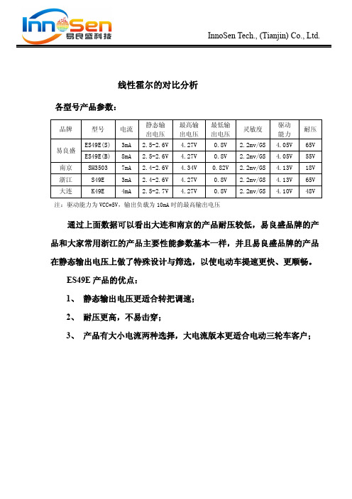
各厂家线性霍尔对比
.
InnoSen Tech., (Tianjin) Co., Ltd.
浙江 大连
型号
ES49E(S) ES49E(B) SH3503
S49E K49E
电流
3mA 8mA 7mA 3mA 4mA
静态输 出电压 2.5-2.6V 2.5-2.6V 2.4-2.6V 2.4-2.6V 2.5-2.7V
最高输 出电压 4.27V 4.27V 4.34V 4.27V 4.27V
最低输 出电压 0.8V 0.8V 0.82V 0.8V 0.8V
注:驱动能力为 VCC=5V,输出负载为 10mA 时的最高输出电压
灵敏度
2.2mv/GS 2.2mv/GS 2.2mv/GS 2.2mv/GS 2.2mv/GS
驱动 能力 4.05V 4.05V 4.13V 4.13V 4.10V
耐压
65V 55V 18V 65V 48V
通过上面数据可以看出大连和南京的产品耐压较低,易良盛品牌的产 品和大家常用浙江的产品主要性能参数基本一样,并且易良盛品牌的产品
在静态输出电压上做了特殊设计与筛选,以使电动车提速更快、更顺畅。 ES49E 产品的优点: 1、 静态输出电压更适合转把调速; 2、 耐压更高,不易击穿; 3、 产品有大小电流两种选择,大电流版本更适合电动三轮车客户;
SEC霍尔线性器件SS49E使用手册
SEC霍尔线性器件SS49E使用手册
~ 1 ~
SEC 霍尔线性器件SS49E 产品使用手册
概述:
SS49E 线性霍尔效应传感器是一款体积小,功能多的线性霍尔效应器件,它在永久磁体或电磁体产生的磁场控制下工作。
线性输出电压由电源电压设置并随磁场强度的变化而等比例改变。
先进的内置功能电路设计确保了它的低输出噪声,从而使得该器件的使用无需搭配外部滤波电路。
内置薄膜电阻大大增强了器件的温度稳定性和输出精度。
其工作温度范围宽达-40°C 到150°C ,适用于绝大多数的消费、商业及工业应用。
该器件提供了小外形利用Transis-TOR (SOT ),或在塑料单列直插(SIP3L 平),两个3引脚封装均符合RoHS 标准。
优点和特性:
– 4.5V 到6V 的工作电压范围
–微型系统架构
–低噪声输出
–磁优化封装
–准确的线性输出为外围电路的设计提供了更多灵活性
–工作温度范围宽达-40°C 到150°C
应用实例:
–汽车控制
–磁码读取
–含铁金属探测
–电流检测
–位置探测
封装:
3引脚的SOT23封装 (器件标号后缀为SO) ; 3引脚的
SIP 封装
(器件标号后缀为UA)。
- 1、下载文档前请自行甄别文档内容的完整性,平台不提供额外的编辑、内容补充、找答案等附加服务。
- 2、"仅部分预览"的文档,不可在线预览部分如存在完整性等问题,可反馈申请退款(可完整预览的文档不适用该条件!)。
- 3、如文档侵犯您的权益,请联系客服反馈,我们会尽快为您处理(人工客服工作时间:9:00-18:30)。
ES49E
2)
12. 封装
12.1 UA 封装(TO-92 扁平型)
1.52 0.1 0.75 0.05 1.96 0.1
3 1
0.94 0.1 3.90
45 1
4.0 0.1 3.90
产品型号
ES49E
封装类型
SO (SOT-3L) UA (TO-92)
联系方式:
易良盛科技(天津)有限公司 地址:天津市滨海新区第四大街 80 号天大科技园 A1 栋 2 楼 电话:022-59812098 网址:
©2009-2013 易良盛科技(天津)有限公司 Rev3.0.0.130223 5/5
1
2
3
Hall plate Location 3.0 0.1
49E xxxxx
3 - 0.44 3.90 1 0.05 0.05 3.90 3 - 0.38 3.90 2 3 1.6. 0.1
Active Area Depth: 3 1
0.84(Nom) 6 1
3 1
﹣0.15 ﹣0.04
10. 特性曲线
输出电压与磁场强度曲线
工作电流与工作电压关系曲线
静态输出电压与工作电压关系曲线
输出电压与环境温度曲线
©2009-2013 易良盛科技(天津)有限公司
Rev3.0.0.130223
3/5
数据手册
线性霍尔传感器 11. 使用注意
参数值
8.0 20 -40 ~ 85 -65 ~ 150
单位
V mA ℃ ℃
8. 电学特性
参数
工作电压 工作电流 输出电流 响应时间 静态输出电压 最低输出电压 最高输出电压
符号
VCC ICC IOUT TACK VO B = 0Gs Operating Average
测试条件
最小值
3.5
典型值
最大值
1.27
©2009-2013 易良盛科技(天津)有限公司
Rev3.0.0.130223
4/5
数据手册
线性霍尔传感器
12.2 SO 封装(SOT-23)
Notes: 1). PINOUT:
ES49E
Top View 3
49ymm
1.50 2.65 1.70 2.95
6.5
单位
V mA mA
4.2 1.0 1.5 3 2.25 2.5 0.86 4.23
8.0
uS
2.75 V V V
B = -1500Gs B = 1500Gs
©2009-2013 易良盛科技(天津)有限公司
Rev3.0.0.130223
2/5
数据手册
线性霍尔传感器 9. 磁场特性
ES49E
2. 特点
体积小 精确度高 稳定性好 灵敏度高 可靠性高 低噪声 低功耗
3. 典型应用
电动车调速转把 电流检测传感器 接近检测器 运动检测器 齿轮传感器 电动机控制 旋转编码器 铁金属探测器
4. 功能框图
©2009-2013 易良盛科技(天津)有限公司
参数
灵敏度 磁场强度范围 线性度 工作温度 零位漂移 灵敏度温漂
ES49E
测试条件 TA = 25℃
最小值 2.0 ±650 ﹣40 ﹣0.10
典型值 2.5 ±1000 ﹣0.007
最大值 3.0
单位 mV/Gs Gs 量程的%
100 0.10 0.05 0.185
℃ %/℃ %/℃
TA ≥ 25℃ TA < 25℃
数据手册
线性霍尔传感器 1. 概述
ES49E 为小型、通用、线性霍尔效应传感器,其输出 信号电平决定于施加在器件敏感面的磁场强度, 随磁场强度 成比例地变化。当 ES49E 处于零磁场条件时,其输出电压 是电源电压的一半。S 磁极出现在 ES49E 标记面时,输出 电压将随磁场强度增加而线性升高;相反,N 磁极将使输出 电压随磁场强度增加而线性降低。ES49E 具有低噪声输出 的特点,不再需要采用外部滤波。它还包括薄膜式电阻,能 提高温度的稳定性和准确性。 工作温度范围为-40℃至 85℃, 适用于各种商业用户和工业环境。
邮编:300457 传真:022-59812096
Rev3.0.0.130223
1/5
数据手册
线性霍尔传感器 5. 芯片外观图
ES49E
6. 管脚描述
管脚名称
VDD GND Output
序号
1 2 3
状态
P P O
描述
电源 地 输出
7. 极限参数
参数
供电电压 输出电流 工作温度 存储温度
符号
VCC IOUT TA TS (TA = 25℃, VCC = 5.0V)
Pin 1 VDD Pin 2 Output Pin 3 GND 2). 所有尺寸均是以毫米为单位; Marking: 49 – 器件型号 ( ES49E ); y – 年份的最后一位; mm – 批次号;
1 1.80 2.00 Side View 2.82 3.02
2
End View
0.70 0.90 3.00 0.30 0.50 3.00
1.05 1.15 3.00 0.00 0.10 3.00
0.10 0.20 3.00 0.30 0.60 3.00
Hall plate location
Bottom View of SOT-23 Package Chip
3
0.8 2 3 1 2 1.45 1.40
0.56 0.66 0.66
13. 订购信息
6 1
Notes:
1). 测量单位:mm;;
14.5
2). 引脚必须避开 Flash 和电镀针孔; 3). 不要弯曲距离封装接口 1mm 以内的引脚线; 4). PINOUT: Pin 1 VDD Pin 2 GND Pin 3 Output
Marking: 49E – 器件型号(ES49E); XXXXX – 批次号;