KZSCR TC-8温控模块说明书(8路温控模块)
ACS-T8说明书
测温式电气火灾监控探测器ACS-T8/3000上海零线电气有限公司目录概述■产品特点ACS-T8测温式电气火灾监控探测器(以下简称温度探测器)是一种独立式的智能型探测器。
温度探测器作为电气火灾监控系统信号处理的中继部分,能通过内置电路及软件对下级终端温度探头传递过来的信号进行智能分析处理,由此可判断出下级终端每一只温度探头的状态(即故障状态、火灾报警状态、正常工作状态),并通过RS485通讯网络将本机(即多台温度探测器的一台)每一只温度探头的故障、报警等信息发送给上级EF-ACS/B256型电气火灾监控设备,主机完成监控、报警的综合处理。
温度探测器具有温度探头故障诊断、报警精度高、可靠性强(能有效防止误报、漏报)、小型化、多功能、简单实用、安装维护方便等特点。
■适用范围适用在电气火灾发生机率最大的工厂、大型库房、办公室、商业建筑、宾馆、住宅及娱乐场所等线路复杂的场所中。
工作原理温度探测器内部电路由单片机、数据存储器、人机对话电路、回路接口电路、多机通讯接口电路等组成。
单片机采用Microchip公司的PIC24F系列单片机,功能强,指令丰富,是广为应用的优秀机种。
人机对话电路主要是由按键输入电路、显示驱动电路、指示灯显示电路及数码管显示电路组成,通过这些电路可设定温度探头的火灾报警阈值,显示测量的温度值,指示温度探头的状态(即故障状态、火灾报警状态、正常工作状态)。
回路接口电路可接收处理下级终端温度探头传递过来的信号。
多机通讯接口电路可将本机下级终端每只温度探头的信息(包括温度值、探头状态)发送给上级EF-ACS/B256型电气火灾监控设备。
温度探测器轮流采集下级终端温度探头传递过来的信号,当判断出温度探头故障时,与此探头相应的故障指示灯就会点亮,并且蜂鸣器发出断断续续的鸣叫声,直到故障排除或值班人员通过“复位”键手动消除后,故障指示灯才会熄灭;当判断出探头的温度值超出火灾报警阈值时,温度探测器就会发出声、光报警信号,值班人员按“消音”键消除音响,然后按温度探测器指示的通道到现场进行相应处理,现场情况处理完毕,值班人员需通过按“复位”键,才能使温度探测器恢复到正常工作状态。
ZH-T08TC 8路热电偶温度测量模块说明书

ZH-T08TC8路热电偶温度测量模块使用说明书(V2.1)1、概述本模块采用高精度32位AD芯片+ARM32位工业级MCU,精度高,抗干扰好。
支持B、C、E、J、K、N、R、S、T九种热电偶型号测温,自由配置,可广泛用于各种温度测量场合。
本模块可以用RS232或RS485,以及以太网做为通信接口,当采用RS232或RS485时,模块可以测量8路热电偶温度;当采用以太网接口时,模块可以测量6路热电偶温度。
可灵活自选Modbus-RTU或Modbus-TCP工业通信协议,与各种组态屏、工控软件以及模组进行可靠通信。
具有以下特点:✧具有宽电源供电9-36V。
✧32位高精度AD高分辨率,误差≤±0.1℃(热电偶为K型时的采样误差,排除热电偶本身误差后的数值)。
✧支持B、C、E、J、K、N、R、S、T多种热电偶温度传感器。
✧采样周期具有340ms,500ms,800ms,1500ms四种速率可设置。
✧具有奇校验、偶校验、无校验、2停止位等多种通讯格式可自由设定。
✧具有℃(摄氏度)与℉(华氏度)两种温度单位的数据寄存器可自由读取。
✧热电偶输入与电源、通讯隔离,可靠性高。
2、产品主型号ZH-T08TC-14N18路测温,RS485+RS232接口;ZH-T06TC-34N16路测温,以太网接口;3、性能指标量程范围:热电偶型号范围B型50~1700℃C型0~2320℃E型-200~900℃J型0~750℃K型-200~1250℃N型-270~1300℃R型0~1450℃S型0~1450℃T型-200~350℃精度误差(K型热电偶):此误差为排除热电偶本身误差后的采样误差。
误差采样速率误差采样速率±0.1℃1500ms±0.3℃500ms±0.1℃800ms±3℃340ms 支持测温传感器类型:B、C、E、J、K、N、R、S、T(可自由配置);分辨率:0.1℃;工作温度:-40℃~+70℃;温度漂移:≤±5ppm/℃;数据更新时间:可自主选择340ms,500ms,800ms,1500ms(默认)4种刷新时间;隔离耐压:>1500V DC;辅助电源:+9V~+36VDC;额定功耗:<0.5W;输出接口:有一个可跳线选择RS485或RS232的接口,和一个独立的以太网接口,这两个接口可选配一个或两个同时选配;通讯协议:Modbus-RTU或Modbus-TCP通讯协议可配置;通讯波特率:4800、9600、19200、38400、57600、115200bps;数据格式:8个数据位,可自由配置无校验/奇校验/偶校验、1位停止位/2位停止位;外观尺寸:115*90*40mm;RS485口出厂参数:地址为1号,波特率9600,无校验,8个数据位,1个停止位;RJ45网口出厂参数:TCP server模式,IP:192.168.2.7,端口号:20108;网页登录用户名:admin,登录密码:admin;4、外形尺寸图5、端子接线定义图5.1拨码开关配置与通讯接口配置说明PCB上的拨码开关可以定义硬件地址,如下:表1拨码开关位功能详情第8位保留无效第7位保留无效第6位设备地址设置置ON时,采用MODBU协议可更改的软件设备地址;置非ON时,开关第5位至第1位对应设置设备地址bit4至bit0(单位:mm)位(bit7至bit5默认为0)第5至1位地址Bit4至Bit0位第6位置非ON 时,对应设备址址Bit4--Bit0,举例如下:Bit4=OFF ,Bit3=OFF ,Bit2=OFF ,Bit1=OFF ,Bit0=ON ,地址为1Bit4=OFF ,Bit3=OFF ,Bit2=OFF ,Bit1=ON ,Bit0=OFF ,地址为2Bit4=OFF ,Bit3=OFF ,Bit2=OFF ,Bit1=ON ,Bit0=ON ,地址为3。
点块AC8输入 8继电器输出模块说明书

Installation Instructions POINTBlock ac 8 Input/8 Relay Output Module(Cat. No. 1734D-IA8XOW8, -IA8XOW8S) ArrayThis 1734D input/output module is a DIN-rail mounted device with an integrated DeviceNet communication interface, 8 ac inputs and 8 relay outputs, removable terminations, and a PointBus expansion port. The expansion port allows you to add up to a maximum of 12 additional POINT I/O modules.The module includes a non-isolated DeviceNet communication interface. The 24V dc from the DeviceNet connection powers a non-isolated dc/dc converter that generates +5V dc which powers the POINTBlock electronics and connects to the PointBus port to power the expansion I/O electronics.The 1734-IA8XOW8 uses cage-clamp terminations, and the1734-IA8XOW8S uses spring-clamp terminations.2 POINTBlock ac 8 Input/8 Relay Output ModuleWhatever field power you supply is connected to the internal field-power bus. For example, if 120V ac is applied to the power connections, there will be 120V ac applied to the modules through the internal field-power bus.POINT I/O modules to the right of the module will also have that internal power bus voltage applied, unless you use a 1734-FPD to interrupt and change the field power-bus voltage.ConnectorPointBus Expansion Port (allows expansion of up to 12 POINT I/O modules)I/O ConnectionsPower Connections 41971120V acPOINTBlock ac 8 Input/8 Relay Output Module 3To set the node address, set the combination of 1’s and 10’s tocorrespond to the required address. (For example, for 61, set the 10’s switch to 6 and the 1’s switch to 1.)POINTBlock is designed to be grounded through the DIN rail to chassis ground. To assure proper grounding of POINTBlock and POINT I/O adapters and terminal bases to chassis ground, the recommended DIN rail material is zinc-plated, yellow-chromated steel. Mount POINTBlock, POINT I/O adapters and terminal bases only to zinc-plated, yellow-chromated steel.4200410’s Node Address Rotary Switch4 POINTBlock ac 8 Input/8 Relay Output ModuleWiring120V acRTB 0RTB 1RTB 2RTB 3RTB 4This supply will be connected to the internal power bus. NC = No connectionL2/N = AC Return/Neutral L1 = AC Power41976POINTBlock ac 8 Input/8 Relay Output Module 5Input WiringNote: When connecting more than 1 wire in a termination point, make sure that both wires are the same gauge and type.ChannelInput TerminalReturnVoltageRemote Termination Block 10046115722463357Remote Termination Block 24046515762467357120V ac is supplied through the internal power bus.41967acL1 = 120V ac L2 = Return6 POINTBlock ac 8 Input/8 Relay Output ModuleOutput WiringChannel Output Common SupplyRemote Termination Block 30A 00B 21A 11B 32A 42B 63A 53B 7Remote Termination Block 44A 04B 25A 15B 36A 46B 67A 57B7Supply voltage is 120V ac.12/24V dc power for the module is provided by the internal power bus.L1 = 120V ac L2 = ReturnPOINTBlock ac 8 Input/8 Relay Output Module 7N ote: When connecting more than 1 wire in a termination point,make sure that both wires are the same gauge and type.DeviceNet Connector WiringDeviceNet connection-V42132+V CAN - High Shield CAN - Low8 POINTBlock ac 8 Input/8 Relay Output ModuleThe following information applies when operating this equipment in hazardous locations:Informations sur l’utilisation de cet équipement en environnements dangereux :Products marked “CL I, DIV 2, GP A, B, C, D” are suitable for use in Class I Division 2 Groups A, B, C, D, Hazardous Locations and nonhazardous locations only. Each product is supplied with markings on the rating nameplate indicating the hazardous location temperature code. When combining products within a system, the most adverse temperature code (lowest “T” number) may be used to help determine the overall temperature code of the system. Combinations of equipment in your system are subject to investigation by the local Authority Having Jurisdiction at the time of installation.Les produits marqués "CL I, DIV 2, GP A, B, C, D" ne conviennent qu’à une utilisation en environnements de Classe I Division 2 Groupes A, B, C, D dangereux et non dangereux. Chaque produit est livré avec des marquages sur sa plaque d’identification qui indiquent le code de température pour les environnements dangereux. Lorsque plusieurs produits sont combinés dans un système, le code de température le plus défavorable (code detempérature le plus faible) peut être utilisé pourdéterminer le code de température global dusystème. Les combinaisons d’équipements dans le système sont sujettes à inspection par les autorités locales qualifiées au moment de l’installation.EXPLOSION HAZARD •Do not disconnectequipment unlesspower has beenremoved or the areais known to benonhazardous. •Do not disconnectconnections to thisequipment unlesspower has beenremoved or the areais known to benonhazardous.Secure any externalconnections thatmate to thisequipment by usingscrews, slidinglatches, threadedconnectors, or othermeans providedwith this product.•Substitution ofcomponents mayimpair suitability forClass I, Division 2.•If this productcontains batteries,they must only bechanged in an areaknown to benonhazardous.RISQUE D’EXPLOSION •Couper le courant ou s’assurer quel’environnement estclassé non dangereuxavant de débrancherl'équipement.•Couper le courant ou s'assurer quel’environnement estclassé non dangereuxavant de débrancherles connecteurs. Fixertous les connecteursexternes reliés à cetéquipement à l'aidede vis, loquetscoulissants,connecteurs filetés ouautres moyens fournisavec ce produit.•La substitution decomposants peutrendre cetéquipement inadaptéà une utilisation enenvironnement deClasse I, Division 2.•S’assurer quel’environnement estclassé non dangereuxavant de changer lespiles.POINTBlock ac 8 Input/8 Relay Output Module 9Specifications - 1734D-IA8XOW8, -IA8XOW8SInput SpecificationsON-State Voltage65V ac minON-State Current 5.0mA minOFF-State Voltage43V ac maxOFF-State Current 2.5mA maxNominal Input Impedance17.0kΩInput Delay Time OFF to ONON to OFF 20ms hardware + (0-65ms selectable) 20ms hardware + (0-65ms selectable)External AC Power SupplyVoltage120V ac, 60Hz nominalExternal AC Power SupplyVoltage Range85-132V ac, 47-63HzOutput SpecificationsRelay Type Form A, normally open (N.O.)Single Pole, Single Throw (SPST)Output Voltage Range (load dependent)********************* ******************* ********************* ******************** ********************Output Current Rating (at rated power)Resistive2A @ 5-30V dc0.5A @ 48V dc0.25A @ 125V dc2A @ 125V ac2A @ 240V acInductive2.0A steady state @ 5-30V dc, L/R - 7ms 0.5A steady state @ 48V dc, L/R = 7ms 0.25A steady state @ 125V dc, L/R = 7ms 2.0A steady state, 15A make @ 125V ac, PF = cos θ = 0.42.0A steady state, 15A make @ 240V ac, PF = cos θ = 0.410 POINTBlock ac 8 Input/8 Relay Output ModulePower Rating250W max for 125V ac resistive loads480W max for 240V ac resistive loads60W max for 28.8V dc resistive loads24W max for 48V dc resistive loads31W max for 125V dc resistive loads250VA max for 125V ac inductive loads480VA max for 240V ac inductive loads60VA max for 28.8V dc inductive loads24VA max for 48V dc inductive loads31VA max for 125V dc inductive loads Minimum Load10mA per pointInitial Contact Res.30mΩSwitching Frequency 1 operation/3s at rated loadBounce Time 1.2ms averageExpected Contact Life300K cycles resistive; 100K cycles inductive Maximum OFF-State Leakage 1.5mA maxOutput Delay Time10ms max ON/OFFPointbus Output Current1A max @ 5V ac outputDeviceNet Current95mA maximum for POINTBlock350mA for maximum with expansion of12 POINT I/O modulesNumber of POINT I/OExpansion Modules12 maximum added at expansion portIsolation Voltage1250Vrms or 2121V dc for 1s between user powerand DeviceNetIndicators 1 red/ green module status indicator1 red/green network status indicator16 I/O status indicators (8 input/8 output) Power Dissipation 2.0W maximum @ 24V dcPower Consumption8.2W maximum @ 24V dcField Power Bus Supply Voltage Voltage Range Supply Current 24V dc nominal 10-28.8V dc 10A maxDimensions Inches(Millimeters)3.00H x 2.36W x 5.25L (76.2 Hx 60.0W x 133.4L)POINTBlock ac 8 Input/8 Relay Output Module 11Publication 1734-5.23 - February 2000Environmental Conditions Operational Temperature Storage Temperature Relative Humidity Shock Operating Non-operating Vibration-20 to +55o C (-4 to +131o F) -40 to 85o C (-40 to 185o F) 5 to 95% noncondensing 30g peak acceleration, 11(±1)ms pulse width 50g peak acceleration, 11(±1)ms pulse width Tested 5g @ 10-500Hz per IEC 68-2-6Conductors Wire Size Category 14 AWG (2.5mm 2) - 22 AWG (0.25mm 2) solid or stranded max 3/64 inch (1.2mm) insulation max 21Terminal Base Screw Torque 5-7 pound-inches (0.5-0.6 Nm)Field Wiring Terminations DeviceNet 1 - Black Wire -V 2 - Blue Wire CAN Low 3 - Bare Wire Drain 4 - White Wire CAN High 5 - Red Wire +VField Power Supply 0 - No Connection1 - No Connection 2 - No Connection3 - No Connection 4 - AC return 5 - AC return 6 - AC power 7 - AC powerMass 13.87 oz/393.41 gramsAgency Certification (when product is marked)•C-UL Listed •C-UL Class I, Division 2 Groups A, B, C and D certified•UL listed•CE marked for all applicable directives•C-Tick marked for all applicable acts1Use this conductor category information for planning conductor routing. Refer to publication 1770-4.1, “Industrial Automation Wiring and Grounding Guidelines for Noise Immunity.”Publication 1734-5.23 - February 2000PN 957236-90© 2000 Rockwell International Corporation. Printed in USA。
TC系列多路温度测试仪说明书

TC系列多路温度测试仪说明书OPERATION MANUALTC系列多路温度测试仪1目录第一章快速入门 (5)1.1 前面板介绍 (5)1.2 后面板介绍 (5)1.3 按键功能描述 (6)1.4 指示灯功能描述 (6)1.5 出厂标准附件 (7)第二章技术规格 (7)主要技术参数 (7)2.12.2 补充特性 (7)第三章面板操作 (8)3.1 基本测量模式3.1.1 定点测量模式 (8)3.1.2 巡检测量模式 (8)3.2 设置操作 (8)第四章仪器通讯协议 (10)4.1 通讯设置 (10)4.2 帧格式 (10)4.3串口通讯命令字快速扫描 (11)4.4命令字的使用 (11)第五章注意事项 (16)第六章常见问题及解决方法 (16)6.1 仪器开机不能正常显示 (16)6.2 温度测量结果不对及出错 (17)2安全请勿自行在仪器上安装替代零件,或执行任何未经授权的修改。
请将仪器送回给威博科技有限公司的维修部门进行维修,以确保其安全特性。
请在购买和使用仪器前仔细参考本手册,以避免产生经济纠纷或仪器损坏。
仪器内部无操作人员可维修的部件。
若需维修服务,请联络受过训练的维修人员。
品质保证TC系列多路温度测试仪完全达到手册中所标称的各项技术指标。
售后服务威博科技有限公司承诺对本产品自购买日期起给予一年的质量保证~服务限制售后服务不适用于因以下情况所造成的损坏:顾客不正确或不适当的维修产品;未经授权的修改和误用;顾客自行安装的电路造成的损坏,或顾客使用自己的产品造成的瑕疵。
通告本手册的内容如有更改,恕不另行通知。
注意为了保证测量精度,建议开机十分钟后开始操作3简介TC系列多路温度测试仪,适用于家电、电机、电热器具等行业的制造厂家和质检部门对温度参数的测量。
为了满足用户的需求,用户可以进行如下选择:8路或16路温度测量、是否配置微型打印机。
本系列产品具有如下功能和优点: , 通过仪器设置,用户可以选择使用铜/铜镍(T型)、镍铬/镍硅(K型)或铁/铜镍(J型)热电偶, 在被测物带电的情况下,仪器可以继续测量使用, 在仪器总的巡检路数范围之内,用户可以选择任何几路进行测量 , 三种巡检速度选择:0.2S、0.4S、1.0S, 两种测量模式选择:定点、巡检, 可以设置测量温度上、下限和报警提示, 具有定时打印功能,并可以设置定时打印间隔时间(在配置微型打印机的情况下), 数字LED显示, 按键操作, 断电设定数据保持记忆功能, 错误自动检测和报警、显示闪烁提示, 可通过计算机进行软件监控附:如客户需要温控器功能,需特别声明。
八路遥控(无线)开关
图 3. 晶振电路与复位电路
其次是控制端单片机上连接的开关部分,本次设计要求是八路无线远程开 关,所以我用了八个开关,因为要控制两片编码芯片,如果用一组 I/O 口控制起 来会非常麻烦,I/O 端口是 CPU 与外部设备、存储器的连接和数据交换的接口。 在 AT89C1 单片机上有 32 个 I/O 口,分为四组,分别是 P0,P1,P2 和 P3,每 组 I/O 口可以发送 8 位二进制数。所以这里我用到了两组 I/O 口 P1 和 P3。八个 开关分别连接单片机的 P1.0~P1.3 口以及 P3.4~P3.7 口,前四个开关控制的是 P1.0~P1.3 口,通过单片机传到 P2 的前四个口,以达到控制第一片 PT2262 编码 芯片的功能;后四个开关控制的是 P3.4~P3.7 口,通过单片机传到 P2 的后四个 口,以达到控制第二片 PT2262 编码芯片的功能;P1 口数据会传到第一片编码芯
1
对于本设计要求,需采用 315MHz 无线模块,实现 1km 范围内 8 路开关的 无线远程控制。 在电路设计好的基础上将原理图用相应软件画出来,并做出相应 的仿真,得出仿真结果。 二、方案论证 方案一: 第一种方案是采用实际单独硬件整合搭配后实现八路无线遥控的功能。其 中,需要把八个开关的闭合状态分别编码,用到 PT2262 芯片编码,在编码之后 需要通过无线发送装置发射出去,再由无线接收装置接收到信号后将信号传给 PT2272 芯片译码器,通过译码器将信号解码得到最终编码,传给被控制的部分 完成控制功能,实现了控制八个无线遥控开关的功能。 这种方法在控制少路开关时比较简单易行,因为 P2262 和 P2272 芯片的输 入端口只有 6 个,但是要控制八个端口的开关就需要两组 P2262 和 P2272 芯片, 这样组合后, 要完成八路控制功能就变得不好实现了。首先面临解决的问题是两 组芯片的选择问题, 其次就是当多路开关按下时, 无线口输出端的数据冲突问题, 最后还有无线接收端的数据冲突问题。 要解决这些问题,就需要用到多个门电路,555 延时芯片,编码器,译码器 和数据锁存器等元件,如果在实际中实现功能会比较麻烦,元件越多出现错误率 就越高。 既然在硬件方面难以实现八路无线遥控开关的功能,我便想到了用软件 的方式实现。既然想到用到了软件来实现,那就必然要用到单片机。于是便产生 了第二个方案。 方案二: 现在正是单片机盛行的时候,我们的很多家用电器其中都有用一块或者多块 单片机组成的不同功能的电路模块,单片机的使用,方便了电路的开发者,将原 本需要很大空间和时间搭建的电路图集成起来,只需往其中烧入程序,就能控制 整个电路。 而在实现本次课程设计中八路遥控开关控制电路中,也可以用到单片机,那 就变得简单易行了,而且这样的电路需要的单片机不会太复杂,利用我们所学的 80C51 单片机就能都够实现。 将每一个开关编好地址,再控制其地址就可以了;其中遥控部分采用常用的 315 兆赫兹频率发射器,通过 PT2262 芯片将其编码发射,接收端采用 PT2272 芯片接收译码,实现控制功能。 所以在选择方案是我选择了用单片机的方式实现。用软件程序代替硬件门电 路选择,延时,中断等功能。
TC-8 温控模块,TC-8温控仪编程手册,8路温控模块编程手册
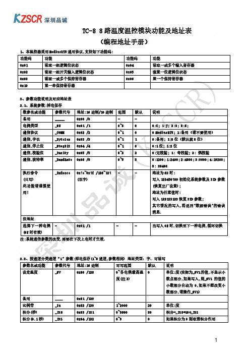
0x28C /652 0x28D /653 0x28E /654 0x28F /655 0x290 /656
0x280 /640 0x281 /641 0x282 /642
0x30C /780 0x30D /781 0x30E /782 0x30F /783 0x310 /784
0x38C /908 0x38D /909 0x38E /910 0x38F /911 0x390 /912
0x817 /2071
同上
冷端(0.1 度)
0x818 /2072
同上
2.4.3、通道温度值:(单位 1 度,只读),数据类型:有符号字
通道
地址:16 进制 /10 进制
说明
通道 1(度)
0x820 /2080
16 位
通道 2(度)
0x821 /2081
同上
通道 3(度)
0x822 /2082
同上
通道 4(度)
功能码功能功能码功能0x01读取一组逻辑位状态0x04读取一或多个输入寄存器0x02读取一组开关输入逻辑位状态0x05强置一位逻辑位状态0x03读取一或多个保持寄存器0x06置一个保持寄存器0x10置一串保持寄存器2参数功能说明及对应地址表21系统参数
TC-8 8 路温度温控模块功能及地址表
(编程地址手册)
2.4、运行参数:(可写的参数)掉电不保存
2.4.1、通道采样数值:(只读),数据类型:无符号字
通道
地址:16 进制 /10 进制
通道 1
0x800 /2048
通道 2
0x801 /2049
通道 3
0x802 /2050
通道 4
0x803 /2051
AC-08 V1.1 市电掉电检测模块应用说明文档
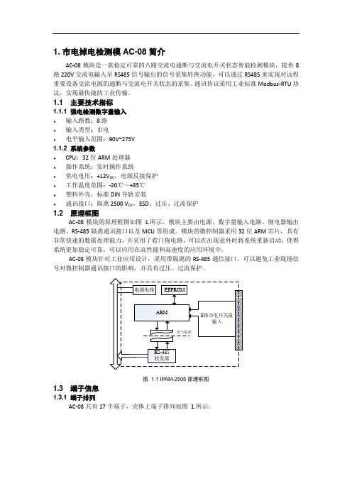
1. 市电掉电检测模AC-08简介AC-08模块是一款稳定可靠的八路交流电通断与交流电开关状态智能检测模块,提供8路220V交流电输入至RS485信号输出的信号采集转换功能,可以通过RS485来实现对远程重要设备交流电源的通断与交流电开关状态的采集。
通讯协议采用工业标准Modbus-RTU协议,实现最快捷的工业传输。
1.1 主要技术指标1.1.1 强电检测数字量输入♦输入路数:8路♦输入类型:市电♦电平输入范围:90V~275V1.1.2 系统参数♦CPU:32位ARM处理器♦操作系统:实时操作系统♦供电电压:+12V DC,电源反接保护♦工作温度范围:-20℃~+85℃♦塑料外壳,标准DIN导轨安装♦通讯接口:隔离2500 V DC,ESD、过压、过流保护1.2 原理框图AC-08模块的原理框图如图1.所示。
模块主要由电源、数字量输入电路、继电器输出电路、RS-485隔离通讯接口以及MCU等组成。
模块的微控制器采用32位ARM芯片,具有非常快速的数据处理能力,并采用了看门狗电路,可以在出现意外时将系统重新启动,使得系统更加稳定可靠,可以应用在高性能和高速度的应用环境中。
AC-08模块针对工业应用设计,采用带隔离的RS-485通信接口,可以避免工业现场信号对微控制器通讯接口的影响,并具有过压、过流保护。
图 1.1 IPAM-2505原理框图1.3 端子信息1.3.1 端子排列AC-08共有17个端子,壳体上端子排列如图1.所示。
图 1.2 AC-08端子排列1.3.2 端子描述AC-08的端子定义说明如下:♦GND,+VIN为模块的电源输入端,GND接电源负端,+VIN接电源正端;♦CFG为模块的默认通信参数硬件使能端子,当此端子接地,模块将以默认的通信参数进行初始化,并且通信参数可配置;♦485GND,485A,485B为隔离的RS-485接口端子,485GND为接口的隔离地,485A 接RS-485收发器的A端,485B接RS-485收发器的B端;♦N 为市电零线接入端子;♦L1~L8 为8路市电火线接入端子;♦DV,DEN为固件更新时的使能接口。
SCD8000 8100温度控制器用户手册说明书
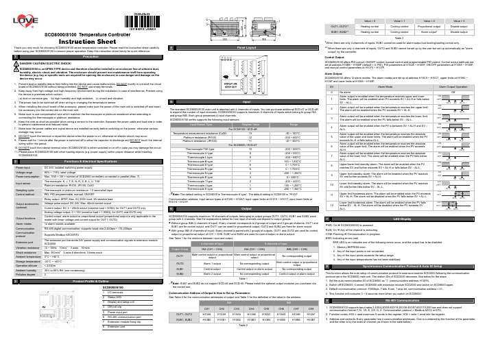
SCD8000/8100 Temperature ControllerInstruction SheetThank you very much for choosing SCD8000/8100 series temperature controller. Please read this instruction sheet carefully before using your SCD8000/8100 to ensure proper operation. Keep this instruction sheet handy for quick reference.!1Precaution!DANGER! CAUTION! ELECTRIC SHOCK!SCD8000/8100 is an OPEN-TYPE device and therefore should be installed in an enclosure free of airborne dust, humidity, electric shock and vibration. The enclosure should prevent non-maintenance staff from operating the device (e.g. key or specific tools are required for opening the enclosure) in case danger and damage on the device may occur .1. Prevent dust or metallic debris from falling into the device and cause malfunctions. DO NOT modify or uninstall the circuitboard of SCD8000/8100 without being permitted. DO NOT use empty terminals. 2. Keep away from high-voltage and high-frequency environment during the installation in case of interference. Prevent usingthe device in premises which contain:(a) dust or corrosive gas; (b) high humidity and high radiation; (c) shock and vibration. 3. The power has to be switched off when wiring or changing the temperature sensor.4. When installing the circuit board of the accessory, please make sure the power of the main unit is switched off and insertthe accessory into the correct slot on the main unit. 5. Make sure to use compensation wire which matches the thermocouple or platinum resistance when extending orconnecting the thermocouple or platinum resistance.6. Keep the wire as short as possible when wiring a sensor to the controller. Separate the power cable and load wire in orderto prevent interference and induced noise. 7. Make sure the power cables and signal device are installed correctly before switching on the power; otherwise seriousdamage may occur. 8. DO NOT touch the terminal or repair the device when the power is on; otherwise an electric shock may occur.9. Please wait for 1 minute after the power is switched off to allow the capacitor to discharge and DO NOT touch the internalwiring within this period. 10. DO NOT touch the internal terminal when SCD8000/8100 is either switched on or off in case you may damage the circuit. 11. Please place SCD8000/8100 with other heating objects (e.g. power supply) within proper distance while installingSCD8000/8100.2Power input DC 24V, isolated switching power supply Voltage range 90% ~ 110% rated voltagePower consumption Max. 10W + 3W × number of SCD2000 controllers connected in parallel (Max. 7) Thermocouple: K, J, T, E, N, R, S, B, L, U, TXK Input sensor Platinum resistance: Pt100, JPt100, Cu50Sampling cycle Thermocouple or platinum resistance: 1.0 second/all input Control method PID, PID programmable, manual, ON/OFFRelay output: SPST, Max. AC 250V load, 3A resistive load Voltage pulse output: DC 24V, Max. 40mA current outputCurrent output: DC 4 ~ 20mA output (resistive load < 500Ω); for OUT1 and OUT2 only Output accessories (optional)Analog voltage output: 0 ~ 10V (resistive load > 1,000Ω); for OUT1 and OUT2 onlyOutput functions Control output, alarm output or proportional output (proportional output is only applicable in themodel with linear voltage and current output for OUT1, OUT2) Alarm modes12 alarm modes availableCommunicationRS-485 digital communication; supports baud rate 2,400bps ~ 115,200bps Communication protocol Supports Modbus ASCII/RTUExtension port The extension port transmits 24V power supply and communication signals to extension module SCD2000.Vibration resistance 10 ~ 55Hz 10m/s 23 axes 10minsShock resistance Max. 300m/s 23 axes 6 directions, 3 times each Ambient temperature 0°C ~ +50°C Storage temperature -20°C ~ +65°C Operation altitude < 2,000mAmbient humidity 35% to 85% RH (non-condensing) Pollution degree23SCD8000/81001 I/O terminals2 Status LED 3Display and setup unit4 DIN rail clip5 Power input port6 RS-485 communication port 7Extension module fixing clip8 Extension port4 Panel Layout5InputThe standard SCD8000/8100 main unit is attached with 4 channels of inputs. You can purchase additional SCD-4T or SCD-4Rto expand the number of input channels. SCD8000/8100 supports maximum 8 channels of inputs which belong to group INA and group INB. Each group possesses 4 input channels. SCD8000/8100 series supports the following input sensors:Input Sensor TypeRegister ValueRangeFor SCD8100 / SCD-4RTemperature measurement resistance (Cu50)13 -50 ~ 150°C Platinum resistance (Pt100)12 -200 ~ 600°C Platinum resistance (JPt100) 11-20 ~ 400°C For SCD8000 / SCD-4TThermocouple TXK type 10-200 ~ 800°C Thermocouple U type 9 -200 ~ 500°C Thermocouple L type 8 -200 ~ 850°C Thermocouple B type 7 100 ~ 1,800°C Thermocouple S type 6 0 ~ 1,700°C Thermocouple R type 5 0 ~ 1,700°C Thermocouple N type 4 -200 ~ 1,300°C Thermocouple E type 3 0 ~ 600°C Thermocouple T type 2 -200 ~ 400°C Thermocouple J type 1 -100 ~ 1,200°C Thermocouple K type-200 ~ 1,300°CNote: The default setting in SCD8000 is “thermocouple K type”. The default setting in SCD8100 is “Pt100".Communication address: Input sensor types at H10A0 ~ H10A7; input upper limits at H1010 ~ H1017; input lower limits atH1018 ~ H101F.6OutputSCD8000/8100 supports maximum 16 channels of outputs, belonging to output groups OUT1, OUT2, SUB1 and SUB2, each group with 4 channels. See the explanations below for how input channels correspond to output groups.Without group INB (4 channels of input): Every channel corresponds to 2 groups of output and 2 groups of alarms. OUT1 and SUB1 are for control output, and OUT1 can be used for proportional output. OUT2 and SUB2 are fixed for alarm output. With group INB (8 channels of input): Every channel is paired with 2 groups of outputs. OUT1 and OUT2 are used for control output or proportional output of CH1 ~ CH8. SUB1 and SUB2 are used for control output or alarm output. See Table 1 for the relations between input and output.4 channels of input 8 channels of inputOutput GroupINA (CH1 ~ CH4)INA (CH1 ~ CH4)INB (CH5 ~ CH8) OUT1 Main control output or proportional output Main control output or proportionaloutputNo corresponding output OUT2 Alarm 1 output No corresponding output Main control output or proportionaloutputSUB1 Control output Control output or alarm output No corresponding output SUB2Alarm 2 outputNo corresponding output Control output or alarm outputTable 1Note: SUB1 and SUB2 do not support SCD-46 and SCD-45. Please install the optional output modules you purchase intothe correct slot.Communication Address of Output & How to Set up Parameters:See Table 2 for the communication addresses of output and Table 3 for the definition of the value in the address. INAINBCH1 CH2 CH3 CH4 CH5 CH6 CH7 CH8 OUT1, OUT2 H10A8 H10A9 H10AA H10AB H10AC H10AD H10AE H10AF SUB1, SUB2H10B0H10B1H10B2H10B3H10B4H10B5H10B6H10B7Table 2Value = 0Value = 1 Value = 2 Value = 3 OUT1, OUT2** Heating control Cooling control Proportional output Disable output SUB1, SUB2**Heating controlCooling controlAlarm output*Disable outputTable 3*When there are only 4 channels of inputs, SUB1 cannot be used for alarm output but heating/cooling control only.**When there are only 4 channels of inputs, OUT2 and SUB2 cannot be set up by the user but set up automatically as "alarmoutput” by the controller. Control Output:SCD8000/8100 offers PID control, ON/OFF control, manual control and programmable PID control. Control output methods are set at address H10B8 ~ H10BF (default = 0: PID), PID parameters at H1028 ~ H105F, ON/OFF parameters at H1058 ~ H106F, and manual control parameters at H1070 ~ H107F. Alarm Output:SCD8000/8100 offers 12 alarm modes. The alarm modes are set up at address H10C0 ~ H10C7, upper limits at H1080 ~ H1087 and lower limits at H1088 ~ H108F.7LED DisplayPWR: On B SCD8000/8100 is powered. RUN: On B Any of the channel is executing. COM: Flashing B Communication in progress ERR: Indicating errors (red)ERR LED is on indicates one of the following errors occur, and the output has to be disabled. 1. Memory EEPROM error.2. Any of the input points is not connected.3. Any of the input points exceeds the setup range.4. Any of the input temperatures has not been stabilized.8Synchronous Communication Protocol & Auto ID SetupThis function allows the auto setup of communication protocol in extension module SCD2000 following the communicationprotocol set in the SCD8000 main unit. The station IDs of SCD2000 decrease. See below for the steps. 1. Set the auto communication ID of SCD8000 as “1” (communication address: H10F8).2. Switch off SCD8000. Connect SCD8000 with extension module SCD2000 and switch on SCD8000 again.3. Default communication protocol: 9,600bps, 7 bits, Even, 1 stop bit, communication address = 01.4. This function will consume 3 ~ 5 seconds more when you switch on SCD8000.9RS-485 Communication1. SCD8000/8100 supports baud rates 2,400/4,800/9,600/19,200/38,400/57,600/115,200 bps and does not supportcommunication format 7, N, 1/8, E, 2/8, O, 2. Communication protocol = Modbus ASCII or RTU. 2. Function codes: H03 = read maximum 8 words in the register; H06 = write 1 word into the register.3. Address and contents: Every parameter has 2 communication addresses. One is numbered by the function of the parameter, and the other is by the order of channel (as shown in the table below).Content Explanation CH1 CH2 CH3 CH4 CH5 CH6 CH7 CH8 Presenttemperature value/input error code Unit; 0.1See Table 5H1000(H1100)H1001(H1200)H1002(H1300)H1003(H1400)H1004(H1500)H1005(H1600)H1006(H1700)H1007(H1800)Set temperature value Unit: 0.1H1008(H1101)H1009(H1201)H100A(H1301)H100B(H1401)H100C(H1501)H100D(H1601)H100E(H1701)H100F(H1801)Max. temperature value Disabled when higherthan default valueH1010(H1102)H1011(H1202)H1012(H1302)H1013(H1402)H1014(H1502)H1015(H1602)H1016(H1702)H1017(H1802)Min. temperature value Disabled when lowerthan default valueH1018(H1103)H1019(H1203)H101A(H1303)H101B(H1403)H101C(H1503)H101D(H1603)H101E(H1703)H101F(H1803)Error temperature value -999 ~ +999Unit: 0.1°CH1020(H1104)H1021(H1204)H1022(H1304)H1023(H1404)H1024(H1504)H1025(H1604)H1026(H1704)H1027(H1804)Proportional band value (Pb) 0 ~ 9,999Unit: 0.1H1028(H1105)H1029(H1205)H102A(H1305)H102B(H1405)H102C(H1505)H102D(H1605)H102E(H1705)H102F(H1805)Ti value 0 ~ 9,999H1030(H1106)H1031(H1206)H1032(H1306)H1033(H1406)H1034(H1506)H1035(H1606)H1036(H1706)H1037(H1806)Td value 0 ~ 9,999H1038(H1107)H1039(H1207)H103A(H1307)H103B(H1407)H103C(H1507)H103D(H1607)H103E(H1707)H103F(H1807)Integration default 0.0 ~ 100.0%Unit: 0.1%H1040(H1108)H1041(H1208)H1042(H1308)H1043(H1408)H1044(H1508)H1045(H1608)H1046(H1708)H1010(H1808)Proportional control offset error value, when Ti = 0 0.0 ~ 100.0%Unit: 0.1%H1048(H1109)H1049(H1209)H104A(H1309)H104B(H1409)H104C(H1509)H104D(H1609)H104E(H1709)H104F(H1809)Proportional band coefficient of output 1 and output 2 0.01 ~ 99.99Unit: 0.01H1050(H110A)H1051(H120A)H1052(H130A)H1053(H140A)H1054(H150A)H1055(H160A)H1056(H170A)H1057(H180A)Dead band ofcontrol output 1 & output 2. -99.9 ~ 999.9H1058(H110B)H1059(H120B)H105A(H130B)H105B(H140B)H105C(H150B)H105D(H160B)H105E(H170B)H105F(H180B)Hysteresis for output 1 0 ~ 9,999Unit: 0.1%H1060(H110C)H1061(H120C)H1062(H130C)H1063(H140C)H1064(H150C)H1065(H160C)H1066(H170C)H1067(H180C)Hysteresis for output 2 0 ~ 9,999Unit: 0.1%H1068(H110D)H1069(H120D)H106A(H130D)H106B(H140D)H106C(H150D)H106D(H160D)H106E(H170D)H106F(H180D)Read/write output 1 value Unit: 0.1 %H1070(H110E)H1071(H120E)H1072(H130E)H1073(H140E)H1074(H150E)H1075(H160E)H1076(H170E)H1077(H180E)Read/write output 2 value Unit: 0.1 %H1078(H110F)H1079(H120F)H107A(H130F)H107B(H140F)H107C(H150F)H107D(H160F)H107E(H170F)H107F(H180F)Upper limit for alarm output Alarm enabledwhen temperatureexceeds upper limitH1080(H1110)H1081(1210)H1082(H1310)H1083(H1410)H1084(H1510)H1085(H1610)H1086(H1710)H1087(H1810)Lower limit for alarm output Alarm enabledwhen temperaturefalls below lowerlimitH1088(H1111)H1089(H1211)H108A(H1311)H108B(H1411)H108C(H1511)H108D(H1611)H108E(H1711)H108F(H1811)Tuning for upper limit of analog output Current (4 ~ 20mA)or voltage outputtuningH1090(H1112)H1091(H1212)H1092(H1312)H1093(H1412)H1094(H1512)H1095(H1612)H1096(H1712)H1097(H1812)Tuning for lower limit of analog output Current (4 ~ 20mA)or voltage outputtuningH1098(H1113)H1099(H1213)H109A(H1313)H109B(H1413)H109C(H1513)H109D(H1613)H109E(H1713)H109F(H1813)Input sensor type See “Input” section H10A0(H1114)H10A1(H1214)H10A2(H1314)H10A3(H1414)H10A4(H1514)H10A5(H1614)H10A6(H1714)H10A7(H1814)Output function for output 1 0: heating1: cooling2: proportionaloutputH10A8(H1115)H10A9(H1215)H10AA(H1315)H10AB(H1415)H10AC(H1515)H10AD(H1615)H10AE(H1715)H10AF(H1815)Output function for output 2 0: heating (default)1: cooling2: alarmH10B0(H1116)H10B1(H1216)H10B2(H1316)H10B3(H1416)H10B4(H1516)H10B5(H1616)H10B6(H1716)H10B7(H1816)Control method 0: PID1: ON-OFF2: manual3: PIDprogrammableH10B8(H1117)H10B9(H1217)H10BA(H1317)H10BB(H1417)H10BC(H1517)H10BD(H1617)H10BE(H1717)H10BF(H1817)Alarm 1 output mode See “Alarm Output”sectionH10C0(H1118)H10C1(H1218)H10C2(H1318)H10C3(H1418)H10C4(H1518)H10C5(H1618)H10C6(H1718)H10C7(H1818)Alarm 2 output mode See “Alarm Output”sectionH10C4(H1518)H10C5(H1618)H10C6(H1718)H10C7(H1818)Heating/cooling cycle for output 1 1 ~ 99 seconds0 = 0.5 secondH10C8(H1119)H10C9(H1219)H10CA(H1319)H10CB(H1419)H10CC(H1519)H10CD(H1619)H10CE(H1719)H10CF(H1819)Heating/cooling cycle for output 2 1 ~ 99 seconds0 = 0.5 secondH10D0(H111A)H10D1(H121A)H10D2(H131A)H10D3(H141A)H10D4(H151A)H10D5(H161A)H10D6(H171A)H10D7(H181A)Run/Stop the control 0: stop1: executing2: program stops3: program pausesH10D8(H111B)H10D9(H121B)H10DA(H131B)H10DB(H141B)H10DC(H151B)H10DD(H161B)H10DE(H171B)H10DF(H181B)Status of PID auto-tuning 0: stop1: executingH10E0(H111C)H10E1(H121C)H10E2(H131C)H10E3(H141C)H10E4(H151C)H10E5(H161C)H10E6(H171C)H10E7(H181C)Positive/negative proportional 0: positive1: negative (slope)H10E8(H111D)H10E9(H121D)H10EA(H131D)H10EB(H141D)H10EC(H151D)H10ED(H161D)H10EE(H171D)H10EF(H181D)Content Explanation CH1 CH2 CH3 CH4 CH5 CH6 CH7 CH8outputOther statuses Other statusesH10F0TemperatureunitH10F1Open specialfunction(H1234)H10F2Return todefault(H1357)H10F3ReservedH10F4ReservedH10F5ReservedH10F6ReservedH10F7ReservedCommunicationspecificationsSee Table 4H10F8Auto IDsetupH10F9ReservedH10FABaud rateH10FBASCII = 0RTU = 1H10FC8 bits=07 bits=1H10FD2 stop=01 stop=1H10FEParityH10FFAddress1 ~ 247Communication Parameter Setting:Content 0 1 2 3 4 5 6Baud rate 2,400bps 4,800bps 9,600bps 19,200bps 38,400bps 57,600bps 115,200bpsParity bit None (N) Even (E) Odd (O)Table 4Error Codes:The error codes can be read from address H1000 ~ H1007. When the input operation is in normal status, H1000 ~ H1007 arefor input values. When input error occurs (except for stable status and input exceeding the range), SCD8000/8100 will readerror codes in H8001 ~ H8002.H1000 ErrordescriptionH8001 EEPROM cannot be written in.H8002 Input sensor is not connected.H8003 Group INB is not connected.Table 5Analog output current tuning scale: 1μA/scaleAnalog output voltage tuning scale: 1mV/scaleReturning to Default Value: Write H1234 into address H10F1 and H1357 into address H10F2. Restart SCD8000/8100.Programmable Communication Parameter Setting:Content Explanation CH1 CH2 CH3 CH4 CH5 CH6 CH7 CH8Read remaining time of the step Unit: sec H111E H121E H131E H141E H151E H161EH171EH181ERead remaining time of the step Unit: min H111F H121F H131F H141F H151F H161F H171F H181FRead the NO. of the currentpattern0 ~ 7 H1120 H1220 H1320 H1420 H1520 H1620 H1720 H1820Read the NO. of the current step 0 ~ 7 H1121 H1221 H1321 H1421 H1521 H1621 H1721 H1821NO. of start pattern 0 ~ 7 H1122 H1222 H1322 H1422 H1522 H1622 H1722 H1822NO. of start step 0 ~ 7 H1123 H1223 H1323 H1423 H1523 H1623 H1723 H1823Programmable Parameter Setting:Content ExplanationPatternPattern1Pattern2Pattern3Pattern4Pattern5Pattern6Pattern7Max. number ofsteps in the pattern0 ~ 7 = N: The patternexecutes from step 0 toN.H2068 H2069 H206A H206B H206C H206D H206E H206FNumber of cycles ofpattern 0 ~ 7execution0 ~ 199: The patternhas been executed for 1~ 200 timesH2070 H2071 H2072 H2073 H2074 H2075 H2076 H2077NO. of current linkpattern0 ~ 8: 8 refers to end ofprogram; 0 ~ 7 refer tothe NO. of next patternH2078 H2079 H207A H207B H207C H207D H207E H207FAddress Default Content Explanation2000H ~ 203FH 0Target temperatures for pattern 0 ~ 7Pattern 0: 2000H ~ 2007HUnit: 0.1°C2080H ~ 20BFH 0Execution time for pattern 0 ~ 7Pattern 0: 2080H ~ 2087HTime: 0 ~ 900 (Unit: 1 min)4. Communication format: H03 = read bit data; H06 = write bit dataASCII Mode:Read Command Read Response Message Write Command Write Response MessageStart word ’:’ Start word ’:’ Start word ’:’ Start word ’:’Machine address 1 ‘0’ Machine address 1 ‘0’ Machine address 1 ‘0’ Machine address 1 ‘0’Machine address 0 ‘1’ Machine address 0 ‘1’ Machine address 0 ‘1’ Machine address 0 ‘1’Command 1 ‘0’ Command 1 ‘0’ Command 1 ‘0’ Command 1 ‘0’Command 0 ‘3’ Command 0 ‘3’ Command 0 ‘6’ Command 0 ‘6’‘1’ ‘0’ ‘1’ ‘1’‘0’Length of responsedata (byte) ‘4’ ‘0’ ‘0’‘0’ ‘0’ ‘0’ ‘0’Read start address ofdata/bit‘0’ ‘1’Data address‘1’Data address‘1’‘0’ ‘F’ ‘0’ ‘0’Read length of data/bit(word/bit) ‘0’Data content in H1000‘4’Write data content‘3’Write data content‘3’Read Command Read Response Message Write Command Write Response Message‘0’ ‘0’ ‘E’ ‘E’‘2’ ‘0’ ‘8’ ‘8’LRC1 check ‘E’ ‘0’ LRC1 check ‘F’ LRC1 check ‘F’LRC0 check ‘A’Data content in H1001‘0’ LRC0 check ‘D’ LRC0 check ‘D’End word 1 CR LRC1 check ‘0’ End word 1 CR End word 1 CREnd word 0 LF LRC0 check ‘3’ End word 0 LF End word 0 LFEndword1CREndwordLFLRC Check:Sum up the contents from “machine address” to “data content”, e.g. H01 + H03 + H10 + H00 + H00 + H02 = H16. Obtain2’scomplement H EA.RTU Mode:Read Command Read Response Message Write Command Write Response MessageMachine address H01 Machine address H01 Machineaddress H01 Machineaddress H01Command H03 Command H03 Command H06 Command H06H10 H10 H10Read start address ofdata H00Length of responsedata (byte)H04 Write data addressH01Write data addressH01H00 H01 H03 H03Read length of data(bit/word) H02Data content 1HF4Write data contentH20Write data contentH20CRC low byte HC0 H03 CRClowbyte HDD CRC low byte HDDCRC high byte HCBData content 2H20 CRC high byte HE2 CRC high byte HE2CRClowbyteHBBCRC high byte H15CRC (Cyclical Redundancy Check) is obtained by the following steps:unsigned int reg_crc = 0xffff;i = 0;while (length--){ reg_crc ^=RTUData[i];i ++;for (j = 0; j < 8; j++){ if (reg_crc & 0x01) reg_crc =(reg_crc >> 1) ^ 0xA001;else reg_crc = reg_crc >> 1;}}return(reg_crc);Software for Setting up Communication on PC: Download the free software on Dwyer’s website.10Connect maximum 7 SCD2000 controllers to SCD8000 by using DIN rail.。
YK-8N 系列多段斜率智能温控表(带 RS485 通信模块) 说明书
YL-8N 系列多段斜率智能温控表(带RS485通信模块)使用说明书★使用此产品前,请仔细阅读“使用说明书”,才能操作无误;并请妥善保存,以便随时参考。
本公司生产的YL-8N 系列多段斜率智能温控表(带RS485通信模块、可选装、下同),生产流程严格按照欧盟CE 标准控制,仪表线路板插件、贴片元件焊接后,需经过低温老化(-20℃)→高温老化(+75℃)→常规通电老化→专用仪表功能检测校验→实际负载检测输出控制功能等五道程序,从而确保产品硬件具有抗谐波干扰范围广,以及在高温或低温环境条件下,仪表的元件参数临界点稳定性能好、工作寿命长等优点。
YL-8N 系列多段斜率智能温控表可选择1-32段控温程序(仪表段号为0-31),每段控温上限到达后可设定在1-9999秒或1-9999分钟之间的保持控温功能。
仪表的主控温软件运用模糊专家精算技术,采用“双曲线伺服控制”方法,使仪表已建立的P、I、D 值主控曲线,在快速跟踪、锁定每段的温度设定点和修正偏差点;同时对一些因加热器功率偏大或偏小、升降温速率偏快或偏慢、散热系数偏高或偏低、同一加热部件多炉分布且因不同的控温点而产生的热效应串扰现象等“较特殊”的控温环境,通过激活仪表的“自整定”功能,仪表能快速地调取出一组适用新控温环境的最优化P、I、D 参数,从而有效地抑制温度较大上冲和快速止跌,达到最佳控温效果,满足不同环境的控温要求。
广泛适用于陶瓷、化工、金属冶炼等高炉控温系统;也可在波峰焊机、回流焊机、涂布机、印刷机、吹膜机、吹瓶机、制杯机、挤出机、联体包装机以及电力发电机组等需要多段、多点控温的机械设备上,配套PC 或PLC 等上位机,组成一个远程多点智能控温系统。
本系列产品已通过欧盟CE 认证。
产品特点:*多段控温程序,1-32段可自由定义升降温曲线,灵活适用加热、制冷等不同工作环境。
*升降温及恒温保持时间可选在1-9999秒或1-9999分钟之间,按控制过程需要自由设定。
多路温控模块

1.6.1 外观尺寸.................................................................................................................................................................7
1.10 布线说明........................................................................................................................................................................13
3.1.2 量程设置...............................................................................................................................................................23
1.7
传感器输入接线示例 ......................................................................................................................................................9
1.1
概述 .................................................................................................................................................................................. 1
EC20-8TC 电偶式温度输入模块说明书

EC20-8TC 电偶式温度输入模块用户手册警告 感谢您购买艾默生网络能源有限公司开发生产的可编程控制器(PLC )。
在使用EC20系列PLC 产品前,请仔细阅读操作指示、注意事项,以减少意外的发生。
负责产品安装、操作的人员必须经严格培训,遵守相关行业的安全规范,严格遵守本手册提供的相关设备注意事项和特殊安全指示,按正确的操作方法进行设备的各项操作。
展模块,如IO 扩展模块、EC20-4DA 、EC20-4AD 、EC20-4AM 等,也可以连接EC20-8TC 。
1 接口描述EC20系列可编程控制器主模块,可以扩展多个IO 扩展模块及特殊功能模块。
连接扩展模块的数量取决于主模块电源提供功率的大小,具体内容请参见《EC20系列可编程控制器用户手册》4.7.6 扩展连接的电源容量计算。
1.1 接口说明EC20-8TC 的扩展电缆接口和用户端子均有盖板,外观如图1-1所示。
1.3 布线说明用户端子布线示意图参见图1-4。
图1-1 EC20-8TC 模块接口外观图(有盖板)打开各盖板后,便可露出扩展电缆接口和用户端子,如图1-2所示。
图1-4 EC20-8TC 用户端子布线示意图图中的①~⑥表示布线时必须注意的6个方面:① 热电偶信号建议通过屏蔽补偿电缆接入。
电缆应远离电源线或其他可能产生电气干扰的电线。
使用长的补偿电缆容易受到噪声的干扰,建议使用长度小于100米的补偿电缆。
补偿电缆存在阻抗,会引入测量误差,特性调整可解决此问题,具体操作参见3 特性设置。
② 如果存在过多的电气干扰,请将屏蔽地FG 与模块接地端PG 相连接。
图1-2 EC20-8TC 模块接口图(打开盖板)③ 将模块的接地端PG 良好接地。
扩展电缆用于将EC20-8TC 接入系统;扩展电缆接口用于将系统其他扩展模块接入。
具体方法参见1.2 接入系统。
④ 模拟供电电源可以使用主模块的辅助输出24Vdc 电源,也可以使用其它满足要求的电源。
温控模块使用说明书
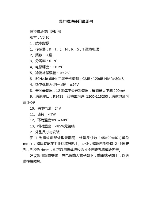
温控模块使用说明书温控模块使用说明书版本:V3.101.技术指标1、传感器:K,J,E,N,R,S,T型热电偶2、路数:8路3、分辨率:0.1℃4、电路精度:±0.2℃5、冷端补偿误差:<±2℃3、50Hz与60Hz工频干扰抑制:CMR>120dB NMR>80dB4、热电偶输入过压保护:±24V8、开关量输出:12路集电极开路输出,每路最大电流200mA9、通讯接口:RS485,波特率可选1200-115200,通信地址可选1-5910、供电电源:24V11、功耗:<3W12、环境温度:0℃~60℃13、相对湿度:<85%无凝结2.外型尺寸与安装图1为模块底部外型装配图,外型尺寸为145×90×40(单位mm),模块装配在工业标准导轨上。
此外,模块两侧各有2个固定孔,孔径为4mm,也可以用螺丝通过这4个固定孔将模块固定。
建议采用垂直安装,热电偶输入端子朝下,输出端子朝上,以方便模块散热。
图1模块底部外型装配图3指示灯、端子、接线和接地给模块上电后,电源指示灯亮;运行指示灯闪烁,表示CPU运行正常。
模块的12个输出都有相应的指示灯,某一路有输出时对应的指示灯亮,断开输出时对应的指示灯熄灭。
L1~L8分别对应第1路输出~第8路输出(Y1-Y8)。
L9~L12分别对应自由输出1~自由输出4(Y9-Y12)。
连接电阻性负载(例如固态继电器)时可按图2或图3接线。
连接电感性负载(例如电磁继电器)时按图3接线,该接法会接通模块内的续流二极管。
第1路热电偶1+接第1路热电偶的正端;第1路热电偶1-接第1路热电偶的负端。
其它各路的连接如此类推。
Y1-Y8端子是第1-8路热电偶的控温输出接线端子,Y9-Y12端子是第1-4路自由输出口接线端子。
X1端子是输入口,输入低电平有效。
模拟地(G0)用于接各热电偶的屏蔽层或负端。
图2温控模块接线图,输出接阻性负载图3温控模块接线,输出接感性或负性负载正确接地可以防止共模电压干扰,共模电压过高会使模块产生测量误差或者使测量的数据不稳定,甚至损坏模坏。
2_8路模拟量采集模块使用说明书2020
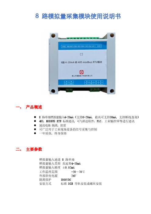
8路模拟量采集模块使用说明书一、产品概述●8路单端模拟量输入4-20mA(支持0-20mA,最高可支持30mA,支持断线查询)●485,MODBUS RTU标准通讯,可与组态软件、PLC、工业触控屏等进行通讯●通讯电路隔离,防雷●可广泛用于工业现场设备的信号采集与控制●一年质保,终身保修二、主要参数模拟量输入通道8路单端模拟量输入类型直流型4-20mA模拟量输入精度±0.02mA工作温度范围-20~70℃外部供电电源24V隔离保护3000VDC安装方式标准DIN导轨安装或螺丝安装三、接线说明四、通讯说明1.通讯参数说明(出厂值):9600,N,8,12.模拟量采集信号采集命令发送010*********crc16(HEX 发送)本模块支持标准:modbus RTU读值功能码:0x3,0x4;写支持功能码:0x6,0x1024V 外部电源输入正极0V 外部电源输入负极A RS485A+B RS485B-PE RS485信号接地端(接大地防雷)RST 恢复出厂设置正端(RST和GND之间短接3秒即可恢复出厂值)GND 恢复出厂设置负端GND 信号地,1-8路模拟量输入负端IN1+第1路模拟量输入正端IN2+第2路模拟量输入正端IN3+第3路模拟量输入正端IN4+第4路模拟量输入正端IN5+第5路模拟量输入正端IN6+第6路模拟量输入正端IN7+第7路模拟量输入正端IN8+第8路模拟量输入正端GND信号地,1-8路模拟量输入负端参数说明9600波特率N(无校验)校验位8数据位1停止位五、地址分布:地址功能0-7(8路)4-20mA对应值(0-10000)8电源电压9内部参考源(可忽略)10-170-20mA对应值(0-20000)18断线标志位(bit0对应第一路)(bit1对应第二路)..*如果bit—on则为断线19-49备用50-578路ad值校准,初始值10000,如果检测值58校准电源电压59备用60通讯站号61波特率62奇偶校验选择63停止位选择波特率代码表2数值波特率0480019600219200338400校验位代码表3数值0默认0无校验1奇校验2欧校验停止位数值0默认01bit12bit。
欧姆龙温度控制器中文手册
䗮⬉⑤
PV ᣝϟ
SP ᣝϟ
䄺ؐ 1 ᣝϟ
䕧ܹ鼠ࡼؐ ᣝϟ
䬂DŽ
䬂DŽ
䬂DŽ ࠊᓣᓔ݇4݇䯁ᯊϡᰒ冫䆹乍DŽ
䬂DŽ
䫕ᅮ䞞ᬒ䬂
ֱᡸᓔ݇ᠧᓔᯊˈৃ䗮䖛ᣝԣ䫕ᅮ䞞ᬒ䬂 ᑊᣝϞ䇗ϟ䇗䬂ᴹᬍ䆒ᅮؐDŽ
Ϟ䇗䬂 ᣝϞ䇗䬂ᴹࡴSP/䄺ؐᰒ冫DŽᣝԣϞ䇗 䬂ϡᬒৃ䖲㓁ࡴᰒ冫ؐDŽᔧݙ䚼ֱᡸᓔ ݇ᠧᓔᯊˈᣝԣ䫕ᅮ䞞ᬒ䬂ᑊᣝϞ䇗䬂DŽ
输入
Pt100
901
温度范围 (选择使用 开关)
78
23
(默认设定: 0)
1,000 850 900
800
700
600
500
400
400
300 200 100
199.9
200
99
0 -100 -99
0.0
-99
0
0
设定编号 0
1
2
3
4
最小设定单位 1℃ 0.1℃
1℃
阴影部分的数值表示默认设定状态。 阴影部分的数值表示默认设定状态。
3. 请不要将设定编号设定为5~9。
• 使用铂电阻,控制模式开关 5: ON
输入
Pt100
1,000 850 900
800
700
600
SP 范围
500 400
400
300
99
0 -100 -99
0.0
-99
0
0
设定编号
ON ON
ࠊᓣᓔ݇
䄺ᓣᓔ݇ (㾕⊼1) ⏽ᑺ㣗ೈᓔ݇
PX1 2 3 4 5 6
INIT ᓔ݇ (㾕⊼2)
ֱᡸᓔ݇
注: 1. 不带报警器的型号上未提供报警模式开关。 2. 正常运行期间INIT开关保持常关。
KS0108控制器系列液晶模块中文说明书(一)128

KS0108控制器系列液晶模块使用说明书(一)感谢您关注和使用我们的液晶产品。
如果您在使用中有任何疑问,请拨打我们的客户服务热线020--87571530寻求技术支持和获取相关资料,我们竭诚为您服务。
您可以登录我们的网站了解最新产品信息。
第一章KS0108控制器系列产品介绍一、 KS0108控制器系列产品主要特性z8位并行数据接口,适配M6800系列时序。
z拥有64×64位(512字节)的显示存储器,其数据直接作为显示驱动信号。
z简单的操作指令。
z低功耗(具体参数见各款产品外形文件)二、 产品列表人和电子有限公司生产的128×32点阵系列和128×64系列产品型号如下: 12832-1 12832-312864-1 12864-2 12864-3 12864-7 12864-1112864-16 12864-17 12864-18三、 主要产品外形图1) 12832-111810.0±0.31.6MAX14.565.0±0.342.0±0.225.0(V .A )18.19(A .A )10.061.020.9@2.54x17=43.180.520.520.050.054-?2.5?1.02.09.017.5106.097.0±0.276.0(V.A)72.91(A.A)110.0±0.32) 12832-318.19(A .A )72.91(A.A)@2.54*17=43.1818165.0±0.361.042.0±0.225.0(V .A )76.0(V.A)97.0±0.2105.0110.0±0.310.0?1.04-?2.5MAX14.5 1.6010.0±0.30.520.520.050.052.09.117.621.011208.3±0.31.6MAX13.033.24(A .A )38.8(V .A )55.0±0.265.0±0.366.52(A.A)73.4(V.A)105.0113.0±0.397.0±0.257.0?1.0@2.54x19=48.2625.44.05.013.115.94-?3.00.040.040.480.484) 12864-28.7±0.3MAX13.50.040.040.480.4812033.24(A .A )128x64 dots@2.54*19=48.261.61013.034-?3?0.866.52(A.A)86.6±0.381.670.7(V.A)61.2±0.356.250.3±0.238.8(V .A )2.54.510.255) 12864-312864-3产品有12864-3C 和12864-3D 两个升级型号,其中12864-3C 是片选高电平有效,12864-3D 是片选低电平有效。
RKC温控器中文说明书
o RKC温控器CD-901 主要结构及功能:·自主校正功能 ·加热/制冷控制 ·外型、接线与RKC一致·大屏LED显示 ·温度报警 ·操作、性能与RKC相同o RKC温控器使用警告·接线警告:- 如果仪器失效或发生错误,可引起系统故障,安装外部保护电路以防止类事故;- 为防止仪器损坏或失效,选用适当的保险丝保护电源线及输入/输出线以防强电源冲击。
·电源供给:- 为防止仪器损坏或失效,用额定电夺供电;- 为防止仪器损坏或失效,所有接线工作完成后方可供电。
·禁止在易燃气体附近使用:- 为防火、防爆或仪器损坏,禁止在有易燃、易爆气体,排方蒸气的场所中使用。
·严禁触及仪器内部:-- 为防止触电或燃烧,严禁触及仪器内部。
只有本厂服务工程师可以检查内部线路或更换部件,仪器内部有高电压、高温部件,非常危险!·严禁改动仪器:- 为防止事故或仪器失效,不禁改动仪器。
·保养:- 为防止触电,仪器报废或失效,只有本厂服务工程师可以更换部件;- 为保证仪器持续且安全使用,应定期保养,仪器内某些部件可能随使用时间的延长而损坏。
RKC温控器操作注意·断电后方可清洁仪器;·清除显示器上的污渍请用软布或棉纸;·显示器易被划伤,禁止使用硬物体操作面板按键,否则会损坏或划伤按键。
RKC温控器概述CH、CD系列智能温度控制器是采用专用微处理的多功能调节仪表,它采用开关电源和表面贴装技术(SMT),因而仪表精致小巧,性能可靠。
特有的自诊断功能,自整定功能和智能控制功能,使操作者可能通过简单的操作而获得良好的效果。
主要特点:热电偶、热电阻、模拟量等多种信号自由输入,量程自由设置;软件调零满度,冷端单独测温,放大器自稳零,显示精度优于0.5%FS;模糊理论结合传统PID方法,控制快速平稳,先进的整定方案;输出可选:断电器触点、逻辑电平、可控硅单相或三相过零或移相触发肪冲或移发脉冲、模拟量。
TC-8 温控模块,TC-8温控仪编程手册,8路温控模块编程手册

小数部分自动为 0,如果不想改变小
数部分,请操作_SV1)
备用
____
0x81 /129
比例带
_Pu
0x82 /130
1~2000
20
单位:度
积分(秒)
_ItH
0x83 /131
0~3600
30
积分=_ItH*10+_ItL
积分(0.1 秒)
_ItL
0x84 /132
0~9
0
如果积分为 0 则取消积分作用
16 位
通道 2(0.1 度)
0x811 /2065
同上
通道 3(0.1 度)
0x812 /2066
同上
通道 4(0.1 度)
0x813 /2067
同上
通道 5(0.1 度)
0x814 /2068
同上
通道 6(0.1 度)
0x815 /2069
同上
通道 7(0.1 度)
0x816 /2070
同上
通道 8(0.1 度)
通道 7
0x806 /2054
通道 8
0x807 /2055
冷端
0x808 /2056
说明 16 位 同上 同上 同上 同上 同上 同上 同上 同上
2.4.2、通道温度值:(单位 0.1 度,只读),数据类型:有符号字
通道
地址:16 进制 /10 进制
说明
通道 1(0.1 度)
0x810 /2064
_AL1
0x89 /137 0x109 /265 0x189 /393 0x209 /521 0x289 /649 0x309 /777 0x389 /905 0x409 /1033
八通道温度控制模块
序号 ⑴ ⑵ ⑶ ⑷ ⑸ ⑹ ⑺⑻ ⑼⑽
序号 ⑴ ⑵ ⑶
FIL
补充说明: 高低温报警 1 1.1 位参数
高、低温报警使能 通 道 8 279 通 道 7 278 通 通 通 通 道 道 道 道 6 5 4 3 对应的位地址( B) 277 276 275 274 通 道 2 273 通 道 1 272
®
WINPARK
�
(苏)制 04000201 号
安装示意图 TPC-8C2
�
MTC8C-EX1
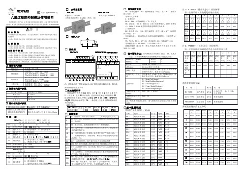
制冷参数说明
八通道温度控制模块使用说明
感谢您选用汇邦产品,在使用前请详细阅读此说明,并妥善保管以便需要 时参考,如有疑问请致电附近的经销商或本公司技术支持热线: 0519-85087082
实物尺寸:145*90*72 实物尺寸:96*90*38 (供参考以实物尺寸为准) (单位:㎜)
通道 2
W200 W201 W202 W203 W204 W205 W206 W207 W208 W232 W233 W234
通道 3
W300 W301 W302 W303 W304 W305 W306 W307 W308 W332 W333 W334
通道 4
W400 W401 W402 W403 W404 W405 W406 W407 W408 W432 W433 W434
通道 5
W500 W501 W502 W503 W504 W505 W506 W507 W508 W532 W533 W534
通道 6
W600 W601 W602 W603 W604 W605 W606 W607 W608 W632 W633 W634
通道 7
W700 W701 W702 W703 W704 W705 W706 W707 W708 W732 W733 W734
SM1201B-8 温度采集模块工具软件说明书

SM1201B-8搜博MODBUS温度采集模块工具软件说明书一、硬件需求 (3)二、软件需求 (3)三、软件安装步骤 (3)四、软件操作 (6)4.1采集与存储界面 (6)4.2参数设置 (8)五、软件适用范围 (10)一、硬件需求硬盘空间大于1G,内存大于256M,CPU单核及以上。
二、软件需求本软件仅限于windows XP,windows2000,windows2003环境使用,window7请使用兼容windows xp模式。
三、软件安装步骤软件安程过程以下面描述为例,实际文字或软件内容部分根据软件版本有所不同。
图1软件安装图标找到“SM1201B多通道PT100采集模块14.12.24.exe”文件名,双击并按以下说明进行安装操作。
图2软件安装过程直接点下一步。
图3软件安装选择安装路径选择合适的安装路径,也可以直接选择默认路径,还可更改到其它目录进行安装。
图4软件安装过程显示选定的安装目标直接点击“安装”。
图5安全卫士360木马防护墙提示若弹出以上木马提示,可以选择“允许本次操作”,本软件绝无木马,请放心安装,让360放行。
若多次提示,可以先关掉防火墙后再进行安装操作。
一直点击【下一步】即可完成安装。
成功安装后,点击桌面快捷键即可运行软件。
四、软件操作图6本产品需要先进行参数设置在进行测试。
4.1采集与存储界面图7此界面共包括MODBUS设置、运行状态指示、串口设置、温度数据、数据读出、命令执行状态等操作按钮。
4.1.1MODBUS设置图8如上图所示,此处为标准MODBUS-RTU命令调试框。
设置项分为设备地址、功能码、起始地址、数据长度等几项。
一般情况下无需更改以下操作,即可进行数据查询操作。
【设备地址】即当前操作的设备ID,值范围一般为1-63,由内置拨码设置。
【功能码】查询输入寄存器的命令码,一般为3,无需修改。
【起始地址】查询所有数据一般从1开始,若查询某一个位置的数据,则可输入对应编号。
