富士温控器说明书(中文)_富士温控器中文说明书
富士电机 PXG数字式温度调节器 <微型控制器X> 说明书

1 2 3 4 5 6 7 8 9 10 11 12 25 26 27 28 29 30 31 32 33 34 35 36
1 2 3 4 5 6 7 8 9 10 11 12 13 14 15 16 17 18
按键操作注意事项/异常时的操作
·报警功能若未正确设定,在仪表发生异常时将无法正确输出 报警,因此运行前请务必进行动作确认。 ”或“ ”。在更换传感器 ·输入断线时,将显示“ 时,请务必先切断电源。
ͳܦ (ᩱឧ) ࠚۘ ൣ᭦ ᭦ ᭦ ᛂ᧫ ߶ᜈᦠ͇ ͳܦ (ൣᆷ) ePXG4 ̀ᛪ ePXG4 ̀ᛪ
ൣ᭦
ͳܦ
᭦
᭦
߶ᜈಳ
ᛂ᧫
ซ
·请不要堵塞本仪表的周围,以免影响散热。 ·请不要堵塞端子上方的通风孔。 ·PXG9型调节器请将安装配件安装到本体中央的安装孔。
-2-
ಕэὙۆᄯ߶ᜈ(පࣰލҸ߶ᜈ) ϙன߶ᜈௐణܷϙᝇ˝ՓՐʽழϙன30˚
●温度传感器与达到或可能产生下表所示电压值的场所之间, 应保持下表所示的爬电距离及空间距离。 若无法确保上述条件,则可能无法达到EN61010标准中承诺 的安全性能。
使用电压或发生电压 [Vrms或Vdc] 最高50 最高100 最高150 最高300 300以上 空间距离(mm) 0.2 0.2 0.5 1.5 爬电距离(mm) 1.2 1.4 1.6 3.0
注意
设置时的注意事项
设置时,请注意避开下列场所。 ·使用时环境温度超过0~50℃范围的场所 ·使用时环境湿度超过45~85%RH范围的场所 ·温度急剧变化,容易结露的场所 ·产生腐蚀性气体 ( 特别是硫化气体、氨等 ) 、可燃性气体的 场所 ·对本体直接产生振动、冲击的场所 ·受水、油、化学药品、蒸汽、热气侵袭的场所 (浸水后会导致漏电、火灾等危险,请送至销售店接受检查) ·粉尘、盐分、铁粉较多的场所 ·感应干扰较大、容易产生静电、磁场、噪声的场所 ·受阳光直射的场所 ·由于辐射热等产生热积蓄的场所
富 士 PXR4温控表说明书
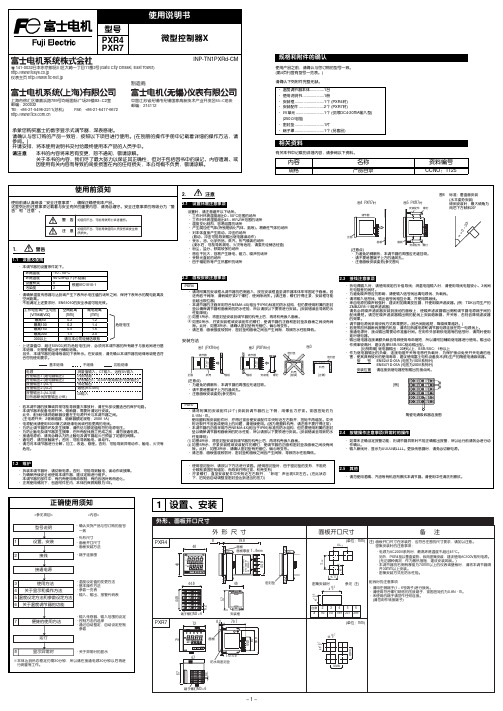
− 1 −− 2 −注) 上段(PV)显示消失(无显示)时,请在参数DP13的设定值上加64。
2接线3使用方法(请在使用前阅读)6关于温度调节器的功能− 3 −− 4 −7为熟练使用温度调节器Modbus RTU 是modicon 公司的商标。
8请在显示异常时阅读* DC4-20mA 输入时,除使用250Ω的外置电阻外,还请作为DC1-5V 输入使用。
注1) 仅同一类型中可以变更代码。
注1) 输入精度为±0.5%FS±1digit±1°C 。
但,采用热敏电阻时,则为±1%FS±1digit 。
R 热电偶0~500°CB 热电偶0~400°C注2) 采用测温电阻时,即使低于-150°C ,也不显示LLLL 。
注3)设定低于上表的最小量程时,不能保证输入精度。
的范围内,有时由于传感器的特性,不能正确显示。
*1 微型控制器X 系列与其他机型的不同点如下表所示,请加以注意。
*2 连接计算机时,需要通信变换器。
另行准备(推荐产品) (株)RA 系统公司生产 RC-77(隔离型) http://www.ras.co.jp (株)lineeye 公司生产 SI-30A(隔离型) http://www.lineeye.co.jp (株)系统sacom 公司生产 KS485(非隔离型) http://www.sacom.co.jp 规 格电源电压:AC100(-15%)~240V(+10%)、50/60Hz 、DC/AC 24V(±10%)功耗:10VA 以下(AC100V),12VA 以下(AC220V),12VA 以下(AC/DC24V)继电器接点输出:控制输出1 1c 接点AC220V/DC30V ,3A(阻性负载)控制输出2 1a 接点AC220V/DC30V ,3A(阻性负载)SSR/SSC 驱动输出*1(电压脉冲输出):ON 时 DC24V(DC17~25V)OFF 时 DC0.5V 以下最大电流 DC20mA 以下负载电阻 850Ω以上DC4-20mA 输出:容许负载电阻 600Ω以下报警输出(最多2点):继电器接点(1a 接点) AC220V/DC30V 1A(阻性负载)加热器断线报警输出:继电器接点(1a 接点) AC220V/DC30V 1A(阻性负载)通信功能*2:RS-485接口传输方式/半双工位串行起止同步传输速度/9600bps通信协议/符合Modbus RTU 或Z-ASCII (PXR 协议)传输距离/最大500m(连接总长度)连接台数/31台数字量输入:输入点数2点 (ON 判定:DC3V 以上,OFF 判定:DC2V 以下)输入接点容量 DC5V / 2mA 输入脉冲宽度 最小0.5秒传送输出:输出精度 ±0.3%以下容许负载电阻 600Ω以下远程SV 输入:输入精度 ±0.5%FS 以下(无输入断线检测功能)设定分辨率 3000以上带输入滤波功能使用及贮存温度:-10°C ~50°C ,90%RH 以下(无结露)-10°C ~45°C(密集安装时)-20°C ~60°C(贮存温度)时间精度:±0.5%以内SSR/SSC 驱动输出DC4-20mA 输出容许负载电阻电压最大电流PXR3DC15V 20mA 100~500ΩPXR4/5/7/9DC24V 20mA 600Ω以下PXV3DC5.5V 20mA 600Ω以下PXV/W/Z DC24V 60mA 600Ω以下[所谓过量程方向]输入在范围之外或异常时的输出方向。
温控器说明书
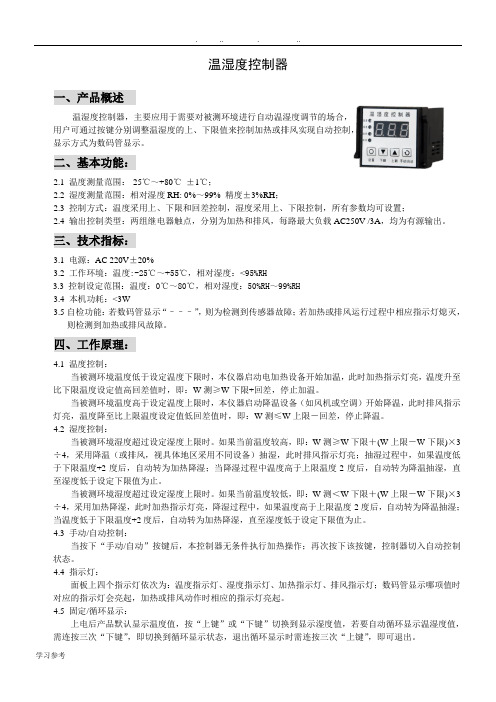
温湿度控制器一、产品概述温湿度控制器,主要应用于需要对被测环境进行自动温湿度调节的场合,用户可通过按键分别调整温湿度的上、下限值来控制加热或排风实现自动控制,显示方式为数码管显示。
二、基本功能:2.1 温度测量范围:-25℃~+80℃±1℃;2.2 湿度测量范围:相对湿度RH: 0%~99% 精度±3%RH;2.3 控制方式:温度采用上、下限和回差控制,湿度采用上、下限控制,所有参数均可设置;2.4 输出控制类型:两组继电器触点,分别为加热和排风,每路最大负载AC250V /3A,均为有源输出。
三、技术指标:3.1电源:AC 220V±20%3.2 工作环境:温度:-25℃~+55℃,相对湿度:<95%RH3.3控制设定范围:温度:0℃~80℃,相对湿度:50%RH~99%RH3.4 本机功耗:<3W3.5自检功能:若数码管显示“–––”,则为检测到传感器故障;若加热或排风运行过程中相应指示灯熄灭,则检测到加热或排风故障。
四、工作原理:4.1 温度控制:当被测环境温度低于设定温度下限时,本仪器启动电加热设备开始加温,此时加热指示灯亮,温度升至比下限温度设定值高回差值时,即:W测≥W下限+回差,停止加温。
当被测环境温度高于设定温度上限时,本仪器启动降温设备(如风机或空调)开始降温,此时排风指示灯亮,温度降至比上限温度设定值低回差值时,即:W测≤W上限-回差,停止降温。
4.2 湿度控制:当被测环境湿度超过设定湿度上限时。
如果当前温度较高,即:W测≥W下限+(W上限-W下限)×3÷4,采用降温(或排风,视具体地区采用不同设备)抽湿,此时排风指示灯亮;抽湿过程中,如果温度低于下限温度+2度后,自动转为加热降湿;当降湿过程中温度高于上限温度-2度后,自动转为降温抽湿,直至湿度低于设定下限值为止。
当被测环境湿度超过设定湿度上限时。
如果当前温度较低,即:W测<W下限+(W上限-W下限)×3÷4,采用加热降湿,此时加热指示灯亮,降湿过程中,如果温度高于上限温度-2度后,自动转为降温抽湿;当温度低于下限温度+2度后,自动转为加热降湿,直至湿度低于设定下限值为止。
Dup(1)PXR7富士温控表说明书

第一组参数参 数 参 数 定 义设 定 范 围STBY暂停设定(在运行/待机间转换)ON:控制暂停(输出:停止,报警:停止) OFF:运行PROG斜坡/保温控制(起动/停止/暂停)OFF:停止 RUN:开始 HLD:暂停LACH解除报警闩锁0:有效 1:无效AT自整定.用于设定P,I,D常数0:OFF 1:标准 2:低PV TM-1显示时间继电器1的剩余时间单位:秒TM-2显示时间继电器2的剩余时间单位:秒AL1报警1设定值AL-L报警1上限值AL-H报警1下限值AL2报警2设定值A2-L报警2上限值A2-H报警2下限值LOC键锁第二组参数参 数 参 数 定 义设 定 范 围P比例带(0:为二位置控制)0.0-999.9%I积分时间(0:积分OFF)0-3200秒D微分时间(0:微分OFF)0.0-999.9秒HYS二位置控制的滞后宽度0-50%FSCOOL冷却侧比例带系数0.0-100.0DB冷却侧比例带的位移(死区)负50.0-+50.0 BAL输出补偿值负100.0-+100.0% AR积分动作禁止点0-100%FSCTRL控制方式PID:PID控制 FUZY:PID+模糊控制 SELF:PID自主整定SLFB PV测量值稳定范围0-100%FSONOF设定HYS(滞后宽度)模式OFF: ON: TC输出1比例周期1-150秒TC2输出2比例周期1-150秒P-N2输入信号代码1-16P-SL量程下限设定-1999-9999P-SU量程上限设定-1999-9999P-DP小数点位置设定0-2P-F o C/o F指定PUOF PV测量值补偿负10-+10%FS SUOF SV设定值补偿负50-+50%FSP-DF输入滤波器时间常数0.0-900.0秒ALM1设定报警1动作模式0-34ALM2设定报警2动作模式0-34STAT斜坡/保温程序段当时位置(只显示)PTN选择斜坡/保温程序的工作模式1:执行第1-4段 2:执行第5-8段 3:执行第1-8段SV-1目标值1在SV限制内TM1R斜坡1段时间0-99h59m TM1S保温1段时间0-99h59m SV-2目标值2在SV限制内TM2R斜坡2段时间0-99h59m TM2S保温2段时间0-99h59m SV-3目标值3在SV限制内TM3R斜坡3段时间0-99h59m TM3S保温3段时间0-99h59m SV-4目标值4在SV限制内TM4R斜坡4段时间0-99h59m TM4S保温4段时间0-99h59m SV-5目标值5在SV限制内TM5R斜坡5段时间0-99h59m TM5S保温5段时间0-99h59m SV-6目标值6在SV限制内TM6R斜坡6段时间0-99h59m TM6S保温6段时间0-99h59m SV-7目标值7在SV限制内TM7R斜坡7段时间0-99h59m TM7S保温7段时间0-99h59m SV-8目标值8在SV限制内TM8R斜坡8段时间0-99h59mTM8S保温8段时间0-99h59mMOD指定斜坡/保温段前和后的控制方式0-15第三组参数参 数 参 数 定 义设 定 范 围P-N1控制动作设定0-19SV-L SV设定值下限0-100%FSSV-H SV设定值上限0-100%FSDLY1报警1延迟时间0-9999秒DLY2报警2延迟时间0-9999秒CT显示电流CT的输入值(只显示)HB设定加热器断线报警的动作值0-50.0A 0.0为HB无效A1HY报警1滞后宽度0-50%FSA2HY报警2滞后宽度0-50%FSA1OP报警1选择设定A2OP报警2选择设定PLC1输入1最小ON脉冲宽度负3.0-103.0%PHC1输入1最小OFF脉冲宽度负3.0-103.0%PLC2输入2最小ON脉冲宽度负3.0-103.0%PHC2输入2最小OFF脉冲宽度负3.0-103.0%PCUT输出限止种类设定0-15OUT1输出值1(MV值)显示OUT2输出值2(MV值)显示RCJ RCJ冷接点辅偿设定ON:RCJ有效 OFF:RCJ无效GAIN PV斜率设定0.001-2000ADJO用户零点调整负50-50%FSADJS用户满席调整负50-50%FSDI-1DI1动作设定0-12DI-2DI2动作设定0-12STNO通信站号设定0-255COM奇偶选择设定0:奇数 1:偶数 2:无PYP PYP(彩色触摸屏)输入类型设定0-235DSP1-DSP9参数显示屏蔽代码0-235DP10-DP13PXR输入量程表输入信号输入量程(o C)输入量程(o F)电阻测温包PT100Ω0-15032-302PT100Ω0-30032-572PT100Ω0-50032-932PT100Ω0-60032-1112PT100Ω-50-100-58-212PT100Ω-100-200-148-392PT100Ω-150-600-238-1112 PT100Ω-150-850-238-1562热电偶J0-40032-752J0-80032-1472K0-40032-752K0-80032-1472K0-120032-2192R0-160032-2912B0-180032-3272S0-160032-2912T-199-200-328-392T-150-400-238-752E0-80032-1472E-199-800-328-1472N0-130032-2372PL20-130032-2372DC电压1-5V DC刻度范围: -1999-9999DC电流4-20MA DC 对电流输入,应并接250Ω电阻,等效转换为1-5VDC输入。
无线温控器说明书中文说明书(改编)
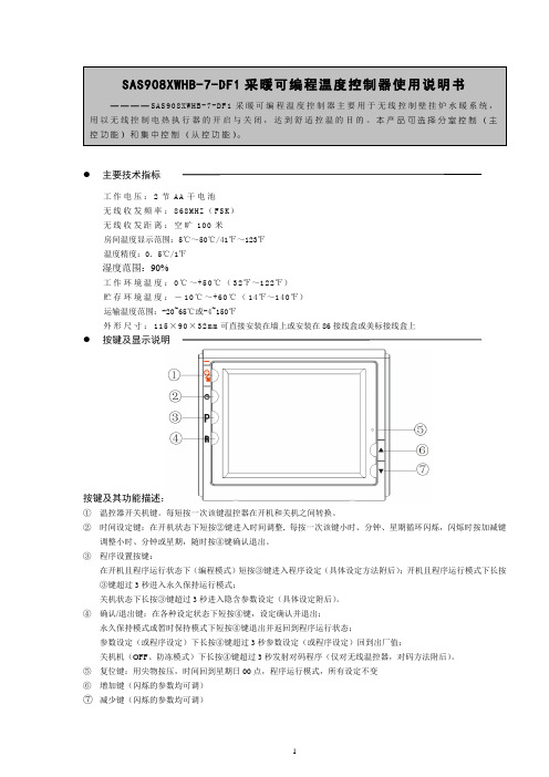
●主要技术指标工作电压:2节AA干电池无线收发频率:868MHZ(FSK)无线收发距离:空旷100米房间温度显示范围:5℃~50℃/41℉~123℉温度精度:0.5℃/1℉湿度范围:90%工作环境温度:0℃~+50℃(32℉~122℉)贮存环境温度:-10℃~+60℃(14℉~140℉)运输温度范围:-20~65℃或-4~150℉外形尺寸:115×90×32m m可直接安装在墙上或安装在86接线盒或美标接线盒上●按键及显示说明按键及其功能描述:①温控器开关机键。
每短按一次该键温控器在开机和关机之间转换。
②时间设定键:在开机状态下短按②键进入时间调整, 每按一次该键小时、分钟、星期循环闪烁,闪烁时按加减键调整小时、分钟或星期,随时按④键确认退出。
③程序设置按键:在开机且程序运行状态下(编程模式)短按③键进入程序设定(具体设定方法附后);开机且程序运行模式下长按③键超过3秒进入永久保持运行模式;关机状态下长按③键超过3秒进入隐含参数设定(具体设定附后)。
④确认/退出键:在各种设定状态下短按④键,设定确认并退出;永久保持模式或暂时保持模式下短按④键退出并返回到程序运行状态;参数设定(或程序设定)下长按④键超过3秒参数设定(或程序设定)回到出厂值;关机机(OFF、防冻模式)下长按④键超过3秒发射对码程序(仅对无线温控器,对码方法附后)。
⑤复位键:用尖物按压,时间回到星期日00点,程序运行模式,所有设定不变⑥增加键(闪烁的参数均可调)⑦减少键(闪烁的参数均可调)显示说明:(各型号温控器并不会显示下列全部图符)操作说明1.隐含参数设置在关机状态下长按键超过3秒进入隐含参数设定第一项,按、 改变参数设置,再按键进入隐含参数设定下一项,按键确认退出,返回到程序运行模式。
如果20秒内没有任何按键被按动,温控器将自动退出隐含菜单设置并返回到关进状态。
如果需要恢复出厂设置,在菜单设置过程中,长按键3秒以上,“DEF ”将显示并闪烁3次后恢复出厂值并回到菜单第一项。
温控器说明书
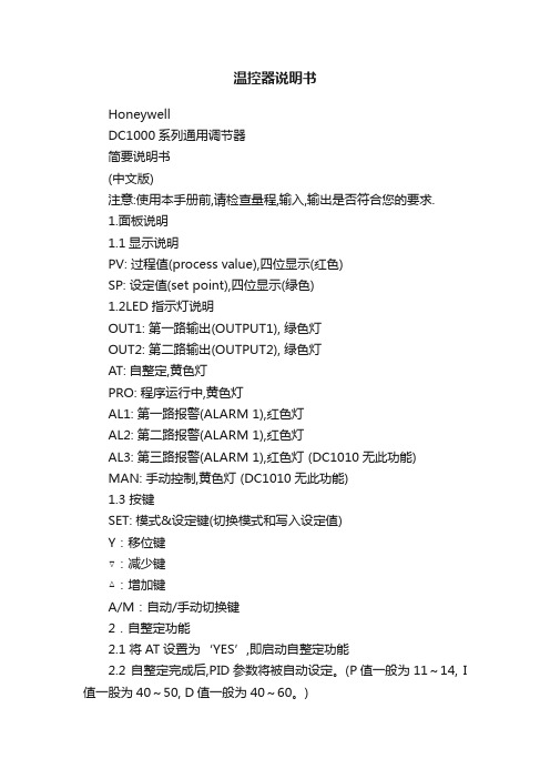
温控器说明书HoneywellDC1000系列通用调节器简要说明书(中文版)注意:使用本手册前,请检查量程,输入,输出是否符合您的要求.1.面板说明1.1显示说明PV: 过程值(process value),四位显示(红色)SP: 设定值(set point),四位显示(绿色)1.2LED指示灯说明OUT1: 第一路输出(OUTPUT1), 绿色灯OUT2: 第二路输出(OUTPUT2), 绿色灯AT: 自整定,黄色灯PRO: 程序运行中,黄色灯AL1: 第一路报警(ALARM 1),红色灯AL2: 第二路报警(ALARM 1),红色灯AL3: 第三路报警(ALARM 1),红色灯 (DC1010无此功能)MAN: 手动控制,黄色灯 (DC1010无此功能)1.3 按键SET: 模式&设定键(切换模式和写入设定值)Y:移位键▽:减少键△:增加键A/M:自动/手动切换键2.自整定功能2.1 将AT设置为‘YES’,即启动自整定功能2.2 自整定完成后,PID参数将被自动设定。
(P值一般为11~14, I 值一股为40~50, D值一般为40~60。
)2.3 ATVL=自整定偏移量,由SP值推导出来(它在自整定时,可防止振荡超过设定点)SP-ATVL=自整定设定值, ATVL=自整定偏移量例如: SP=200℃, ATL=5, 则自整定点是195℃*ATVL务必自整定点在程序类型模式中(195℃)2.4 自整定点失败2.4.1 ATVL值太大→如果不能确定,则设定ATVL=02.4.2系统时间太长→单独设定PID参数3. 故障信息(注意)当有“*”标记的故障发生时,控制器需要维修4.操作流程各阶层进出及参数的锁定4.1.1按移位键(Y)改变参数。
按下移位键,第一位数开始闪烁。
按增加键(△)或减少键(▽)对此数值作增加或减少,再按移位键到第二位数,当所有数值设定好后,按SET键完成数值设定。
4.1.2SET键也有转换模式的功能,按下SET键会显示下一种模式4.1.3按SET键持续5秒可进入LEVEL2,或同样可返回LEVEL1。
温控器说明书 (2)10页word
通过ISO9002国际质量体系认证conformity Certification of ISO9002 Quality Management SystemBWY(WTYK)-802、803系列变压器温度控制器SERIES TRANSFORMER TEMPERATURE CONTROLLER使用说明书DESCRIPTION & OPERATION INSTRUCTIONS杭州华立仪表有限公司HANG ZHOU HUALI INSTRUMENT & METER GENERAL PLANT感谢您使用本厂产品使用前请认真阅读产品使用说明书THANKS FOR USING OUR PRODUCTSPLEASE READ THE DIRECTIONS BEFORE USE目录一、概况 (1)二、工作原理 (5)三、主要技术指标 (5)四、安装及使用 (5)五、注意事项 (10)六、附录Pt100工业铂电阻分度值表 (11)第 2 页一、概况1、温度控制器根据沈阳变压器研究所制订的JB/T6302-92《变压器用压力式温度计》标准的命名如下:2、温度控制器根据JB/T9236-2019《工业自动化仪表产品型号编制原则》的要求产品命名如下:第 3 页第 4 页二、工作原理变压器温度控制器(以下简称温控器),主要由弹性元件、毛细管、温包和微动开关组成。
当温包受热时,温包内感温介质受热膨胀所产生的体积增量,通过毛细管传递到弹性元件上,使弹性元件产生一个位移,这个位移经机构放大后指示出被测温度并带动微动开关工作,从而控制冷却系统的投入或退出。
BWY(WTYK)-802A、803A温控器采用复合传感器技术,即仪表温包推动弹性元件的同时,能同步输出Pt100热电阻信号,此信号可远传到数百米以外的控制室,通过XMT数显温控仪同步显示并控制变压器油温。
也可通过数显仪表,将Pt100热电阻信号转换成与计算机联网的直流标准信号(0~5V、1~5V或4~20mA)输出。
富士温控表说明书PXF5_9-C 明扬工控网 明扬工控商城专业销售 代理(1)

关于安全规范
为了符合安全要求 , 在使用时请遵守以下规则。未遵守规则的情况下无法符合安全要求。(若 进行违规操作易引发危险。) ………………………………………………………………………………………………………… • 请将说明书建议使用的保险丝安装于外部 , 置于主电源(Mains Circuit)和本装置之间。 • 为免触电 , 请不要直接连接输入端子、SSR 输出端子、电流输出端子、通讯(RS-485)
24V 电源类型的场合,请连接 ELV 电源。 请不要直接连接 SELV 电源,要在 SELV 电源和温度调节计之间设置基础绝缘。直接 连接有触电的危险。 对于 CT 输入,为了防止触电及火灾蔓延,请使用以下规格的电流互感器。
1)设置范畴 2)污染度 3)绝缘要求级别 4)1 次侧最大电压
Ⅱ 2 基础绝缘,补强绝缘或强化绝缘 300V AC rms 或 300V DC
使用说明书
微型控制器 X
型号 : PXF5/9
INP-TN2PXF5/9a-C
注意
确认规格和附件
相关信息
在使用产品之前,请确认该产品与您所要 的型号相同。 (如需查看型号代码,请参考第 20 页。) 确认以下所有附件齐备。
微型控制器
1台
使用说明书
1部面板安装架2个前面防水密封垫1个
其他项订购
请参考本说明书所述项目的详情。
警报输出1~3 (继电器接点)
数字输入1 ~5 通信(RS-485)
功能绝缘(500V AC)
不绝缘
电源(DC/AC 24V)
内部电路
控制输出1(继电器接点) 或
电动阀打开输出
测量值输入 远程SV 输入 电流检测器输入
控制输出2(继电器接点)或 电动阀关闭输出
系列温控器说明书
系列温控器说明书系列温控器说明书尊敬的用户,感谢您选择本公司的系列温控器产品。
为了确保您正确、方便地使用该产品,我们提供了以下详细的功能介绍和使用说明。
一、产品概述本系列温控器具有精确的温度控制功能,可广泛应用于家庭、办公室、工业等各个领域。
产品外观简洁大方,操作简单,表现出色。
二、产品特点1. 温度调节范围广:本系列温控器可设定的温度范围在-40℃至100℃之间,能满足大多数环境的需求。
2. 温度控制精准:采用高精度传感器,温度控制精度可达±0.5℃,确保温度的稳定性和准确性。
3. 多种工作模式:可提供不同的工作模式供用户选择,如恒温模式、定时模式、周期模式等,灵活满足各种使用需求。
4. 易于安装:本系列温控器尺寸小巧,安装简单快捷,配备了详细的安装说明书,即使对电器不熟悉的用户也能轻松完成安装。
三、产品功能1. 温度调节功能:通过旋转开关或数字键盘可调节设定温度,产品将根据设定的温度进行智能控制,保持环境温度稳定。
2. 温度显示功能:产品设有大屏幕液晶显示屏,可实时显示当前环境温度,方便用户查看。
3. 温度保护功能:若环境温度超过设定范围,温控器将自动启动保护功能,通过警报或关闭电源等方式保证设备和用户的安全。
4. 耗电监控功能:温控器可监测实际用电量,并显示在显示屏上,帮助用户合理控制能源使用。
5. 定时功能:用户可设定时间段,温控器将在设定的时间范围内按照预设温度进行工作,方便按需设定温度控制。
四、使用说明1. 安装:根据附带的安装说明书,将温控器安装在合适的位置上。
确保温控器与供电设备连接良好,并保证温控器的电源稳定。
2. 温度调节:通过旋转开关或数字键盘可以调节设定温度。
根据实际需求,旋转开关向左转可降低温度,向右转可升高温度。
3. 温度显示:液晶显示屏上将实时显示当前环境温度,方便用户随时了解温度情况。
4. 温度保护:当环境温度超过设定范围时,温控器将会触发保护功能,通过警报或自动断电等方式提醒用户以保证使用安全。
FUJI PXW控制器使用说明

富士PXW9温度控制仪操作指南名称功能输出1指示灯灯亮为输出1为ON输出2指示灯灯亮为输出2为ONPV(测量值) 指示测量值报警灯检测出报警时灯亮,报警输出为ONSV(设定值) 指示设定值,在设定参数时,指示参数数据SEL键参数选择键选择SV/PV显示,选择参数,选择参数和参数值显示等增/减键改变SV值,顺序选择参数。
在参数设定时,增/减参数数值SV指示灯显示设定值(SV)时,此灯亮注意:当无操作状态持续30秒时,将返回接通电源时的状态,新设定的数据可能没储存。
因此应按SEL键返回初始状态。
一. 基本操作:1.1控制温度SV的设置:按∧键提高设定温度,按∨键降低设定温度(在锁定状态下不能修改)。
1.2第一组参数设定:在PV/SV显示模式下按 SEL键3秒后进入第一组参数设定模式,每按一次SEL键参数将依次显示。
按∧键或∨键可改变设定参数的值。
1.3第二组参数设定在PV/SV显示模式下按SEL键7秒进入第二组参数设定模式,按∧键或∨键可改变设定参数的项目,选定要修改的项目后按SEL键进入参数设定窗口,按∧键或∨键设定参数值,设定完成后按SEL键回到参数项目设置模式,再按∧键或∨键可选择其它参数继续设置。
1.4第三组参数设定在PV/SV显示模式下按SEL键9秒进入第三组参数设定模式,按∧键或∨键可改变设定参数的项目,选定要修改的项目后按SEL键进入参数设定窗口,按∧键或∨键设定参数值。
设定完成后按SEL键回到参数项目设置模式,再按∧键或∨键可选择其它参数继续设置。
二.有关参数的选择:2.1输入信号种类设定(P-n2) 输入信号 输人量程()℃代码(P-n2)输入信号输人量程()℃代码(P-n2)Ptl00 0~150 1 J 0~400 2 Ptl00 0~300 1 J 0~800 2 Ptl00 0~500 1K 0~400 3 Ptl00 0~600 1 K 0~800 3 Ptl00 -50~100 1 K 0~1200 3 Ptl00 -100~200 1 R 0~1600 4 Ptl00-150~600 1B 0~1800 5 热 电 阻Ptl00 -150~850 1S 0~1600 6 T -199~200 7 T-150~4007D C电压DC1~5V16E 0~800 8 E -199~800 8N 0~1300 12 D C 电流 DC4~20mA 刻度范围: -1999~9999对电流输入,应并接250Ω电阻。
温控器说明书
用户订货时需按本说明书的功能分类,注明所需仪表的型号。用户对仪表的传感器规格或其他方面有特殊要求的,订货前请说明。
性能指标
工作温度:-10℃~+55℃
安全指导
在安装、操作和运行本温控器前,请仔细阅读本说明书,并妥善保管。
本温控器有危险电压,并监控电力变压器,如果不按照本说明书的规定操作可能会导致财产损失或人员严重受伤甚至死亡。
只有合格的技术人员才允许操作本温控器,在进行操作之前,要熟悉说明书中所有安全说明、安装、操作和维护规程。本温控器的正常运行取决于正确的运输、安装、操作和维护。
7、手动启停风机功能:
按“手动”键,风机启动,再按“手动”键,风机关闭;若仅按一次“手动”键,风机启动10分钟后自动关闭。
本功能也可以作为测试风机功能用。
8、风机定时启停功能:
温控器提供定时启动风机的功能,用于防止风机长时间不运行而发生故障。用户可在面板上进行0~200个小时任意设置(当设置为0时,表示取消此项功能),定时时间到达后,风机自动运行2分钟后停止。出厂时设置为24小时。风机每次定时启动运行时间为2分钟,用户无法自行修改。
3、风机启停功能:
当三相绕组中任意一相绕组温度达到设定的风机启动温度时,风机自动启动,风机指示
灯亮。当三相绕组温度全部下降到设定的风机停止温度时,风机自动关闭,风机指示灯熄灭。风机继电器触点容量为AC220V/7A。风机如需保护,请外接保护装置。
4、超温报警功能:
当三相绕组中任意一相绕组温度达到设定的超温报警温度时,温控器发出声光报警,并接通报警输出端子,向远方的控制柜送出一开关信号,供控制柜启动声光报警系统。继电器触点容量为:AC220V/3A或DC28V/3A。
PXF5ACY2-FW100说明书
PXF5ACY2-FW100说明书PXF5ACY2-FW100富士温控器顾名思义,温度控制器是一种用来控制温度而无需操作人员的大量参与的仪器。
温度控制系统的控制器从热电偶或RTD等温度传感器接收输入信号后,将实际温度与所需控制温度或设定值进行比较。
然后将输出信号提供给控制元件。
例如,控制器从温度传感器接收输入信号,并将输出信号发送至所连接的加热器或风扇等控制元件。
控制器通常只是整个温度控制系统的一部分,因此在选择适当的控制器时,应对整个系统进行分析和考量。
温控器(Thermostat),根据工作环境的温度变化,在开关内部发生物理形变,从而产生某些特殊效应,产生导通或者断开动作的一系列自动控制元件,或者电子原件在不同温度下,工作状态的不同原理来给电路提供温度数据,以供电路采集温度数据。
流体媒介温度控制器是利用感温流体热胀冷缩及液体不可压缩的原理而实现自动调节。
当控制温度升高时感温液体膨胀产生的推力将热媒关小,以降低输出温度;当控制温度降低时感温液体收缩,在复位装置的作用下将热媒开大,以提高输出温度,从而使被控制的温度达到和保持在所设定的温度范围内。
双金属片温控器工作原理根据物体热胀冷缩原理。
热胀冷缩是物体的共性,但不同物体其热胀冷缩的程度不一样。
双金片的两面是不同物质的导体,在变化的温度下由于胀缩程度不一样而使双金片弯曲,碰到设定的触点或开关,使设定的电路(保护)开始工作。
色温型温控器,工作原理系采用一些涂料在不同的温度下会产生不同的色彩的原理。
比如用液晶在不同温度下,就可以产生不同的颜色,再用摄像头类的色彩采集器以给电路提供不同的数据,从而对电路进行控制。
PXF5ACY2-FW100富士温控器一、PXR型数字温控表的功能特点如下:1. 前面板IP66防水结构,三健式菜单操作;2.标准螺钉接线,无须插座;3. 纵向尺寸比PXW表更短;4. UL/CSA/CE认证标志;5. 测量值大LED红色显示;6. 控制功能多种:简单ON/OFF控制,PID带自动调节控制,模糊及PID带自动调节控制,PID自适应调节控制;7.再传输功能(选件):传感器测量值可以以4-20MA型式传送到PHR型数据记录仪,PLC及个人计算机中;8. 8段斜坡/保温程序控制功能(选件);9. RS-485通讯功能(选件),可与FUJI POD及个人计算机通讯;10.数字输入控制功能(选件):通过一点开关量ON/OFF,可改变设定值SV,控制动作起/停,斜坡/保温控制的开始/ 复位,自动调节功能的起/停,报警锁存的复位、定时器计时开始;11. 加冷却控制(选件):有利于节能;12. 加热断线报警(选件);13. 两点各种报警功能(选件):值报警,区间报警,偏差报警;14. 具有塑机的模糊+PID控制功能:15. 内部定时器功能有机械式的和电子式的,机械式的采用两层热膨胀系数不同金属压在一起,温度改变时,他的弯曲度会发生改变,当弯曲到某个程度时,接通(或断开)回路,使得制冷(或加热)设备工作。
富士(FUJI)FRN-G11UDII电梯专用使用说明书
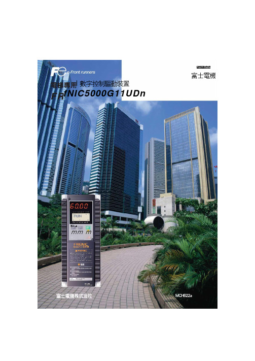
niuicmrDeDe富士電機I數字控制驅動裝置fNIC5000G11UDnBD Lamm mi電梯速度,加速度實測數據螺€動速度 到零速度 的加速度1.2m/S T 電梯速度Om/SO^/S 2電梯加速速②最適合電梯運行的功能•對低速和中速等各種運行,可以自由設定S 字曲綫加减速。
•在常停電時爲保證平眉,把蓄電池運 行功能作爲標准配置。
•密碼功能保證了電梯的平安性,防止已設定的參數被修改。
• PG 反饋信號能分頻輸出。
•無爬行直接停靠。
•當載重不平衡狀態時,對起動進行力矩補償。
③由自整定功能實現高性能運行。
•自整定功能可測定電動機參數實現高性 能運行。
•嶄新的在綫整定功能實現運行中電動機 在温度上升時,額定參數的自動補償。
這樣保證了與温度變化無關的高精度運 行。
④豐富的維護通信功能 •負載率測定 •轉矩輸出時,詳細數據顯示• RS485爲標准配置特長FRENIC5000G11UD II (FRN □□□ G11UD -4C3)系列是專用的數字化控制驅動裝置。
由於±/用了富士電機獨特的矢量控制方式和數字化AVR(數字化自動電壓調節器)等最新控制技術,使得電梯的運 行既平穩又舒適。
具有S 字曲綫加减速運行和化常停電時的蓄①最新控制技術使得電梯的運行既平穩又 速度舒適。
_ ‘‘• PG 反饋電路作爲標准功能内置其中,電高速…梯運行能進行矢量控制。
•富士電機獨特的數字化AVR 保證電梯在 極低速時也能平穩運行,故具有舒適的 低速■■■乘載感。
1標准規範型號FRN □□□ G11UD-4C3 3.7 5.5 7.5 11 15 18.5 22 30 37 45 55 m 3.7 5.5 7.5 11 15 18.5 22 30 37 45 55額定輸出6.8 10.2 14 18 24 29 34 44 57 69 85 3相,380V,400V,415V/50Hz, 380V,400V,440V,460V/60HZ(10 秒)A (最大)A 9.0 13.5 18.5 24.5 32 39 45 58 75 91 11213.5 20.3 27.8 36.8 48.0 58.5 67.5 96 120 150 18217.0 24.5 34.0 46.5 52 69 80.5 105 131 159 19650, 60Hz輸入電源3相,380〜480V, 50/60Hz 3 相,380 〜440V/50HZ380〜480V/60Hz *10)圍電壓:+10〜-15% (相間不平衡率*4): 2%以内頻率:+55%*5) 310V以上時運行可繼| 賣。
FCC Pneumatic Press FCP-C-kN系列用户手册 富士控制 说明书
FCC Pneumatic PressFCP-C-kN seriesInstruction Manual(Version2.02)Fuji Controls Co.,Ltd.April04,2013We thank you for the purchase of our products.In order to ensure proper equipment performance,please read this manual to the end before using our products.This manual should be carefully stored and referred to when necessary.Please use this equipment for ever.●In the case that this equipment is delivered to some other party,it is necessary to deliver the equipment together withthis instruction manual.●This equipment is produced for use in Japan.In the case that it is used in other countries,you should observe thelaws and regulations related to safety in such countries.Contents:Page In order to be used safely:1 It is necessary to observe:1 Press component names:3………………………………………………………………………………………………<Additional explanation>3 Unpacking5 Installation and pre-operational procedures5 <Installation>5……………………………………………………………………………………………………………<Pre-operational procedures>5……………………………………………………………………………………………Operation procedures:6 Die matching(inching,inching motion)6………………………………………………………………………………Maintenance inspection:7 Air circuit diagram:8 Electric circuit diagram(wiring diagram):8 Part table:8 Dimensions drawings and weights:9 Options:10 Output diagram:11 Air consumption amount:11In order to be used safely:The following notice items are described in order to ensure proper usage and to prevent injury to operators orequipment damage.Danger Misuse may cause death or serious injury.Warning Misuse may have a possibility of death or serious injury occurring.Caution Misuse may cause slight or minor injury.This is also indicated that property damage may occur when equipment is not used safely.It is necessary to observe:Business person responsibilityIn industrial safety and hygiene laws,air press is considered as a power press.Regarding business person using this press,the following duties are applied:●Safety and hygiene implementation law;article6,section7When stamping operation is carried out in workshop having a minimum of five presses,a“general foreman in charge of operations”(person completing technology training course for press operation general foreman)should be on duty.●Safety and sanitation rules;article134-3A‘Regular self inspection’should be periodically carried out minimum once a year by qualified personnel.Even if air press does not conform with structure standard,this is judged as a power press if this is used forbending,drawing or crimping.Since there are no guidelines for inspection,applicable items related to Industrial Safety rules;article134,section3.1)to9)are independently inspected.Warning:Power source Regarding power source,AC100V±10%50/60Hz should be used.After verifying the above,enter power.If other power source is connected with,there isa possibility of fire occurrence due to burnout.Air pressure for use Pressure range related to air used in this press should be0.2MPa to0.5MPa.If thisequipment is used at higher pressure than0.5MPa,there is a possibility of piping hosebreakage or press damage occurrence.Operation bench This press should be fixed for use on an operation bench which is sufficient to supportthe weight.If press is not fixed,there is a possibility that either death or serious injurymay occur due to press dropping or tumbling.Guards for preventing cutting Guards for preventing cutting chips from scattering should be established around the chips from scattering press when operation is conducted in circumstance that cutting chips are scattered. Caution related to operation wear Refrain from wearing loose clothing or accessories because there is a possibility ofbodily injury occurrence due to these being caught by press.Put on protectors such assafety cap,protector glasses,safety shoes,mask or gloves if necessary.Press operation,maintenance or Only trained operators should carry out press pre-operational inspection,operation, inspection by trained operator maintenance,die replacement or adjustment operation.It should be displayed for otheroperators to notice that operation is being carrying out.The operation should be carriedout while verifying that other operators do not touch any component.Prohibition of removing acrylic It is absolutely prohibited to remove acrylic cover for mechanical stopper or safety device cover or safety device and or to change installation position.If press is operated without cover or safety device, changing installation position there is a possibility of bodily injury occurrence due to a part of body being caught bypress.Mechanical stopper adjustment Mechanical stopper adjustment should be carried out when press ram stops after risingand no other operator should be in the vicinity of push button switch.If push button switch is mistakenly pushed by other operator when adjustment is carriedout,there is a possibility of slight or serious injury occurrence due to a part of bodybeing caught by press.In drawing operation that impact is added,mechanical stopper should not be used andbottom dead center positioning while using die-set should be used instead.Clearance between rotation Clearance between rotation stopping arm and cylinder bottom should be minimum stopping arm and cylinder bottom20mm.portion In the case of narrow clearance,there is a possibility of slight or serious injury occurringwhen press ram rises.Rotation stopping arm is not equipped for adjusting press ram top dead center.Press operation:For press operation,it should be carried out while verifying that no other operator(1)Safety verification when touches any press portion and no obstacles are in the vicinity.operation starts There is a possibility of bodily injury occurrence when preparation operation of diesetting up is carried out by multiple operators.Do not make contact with mechanical stopper,jig,die or rotation stopping arm.Press operation(2)For press operation,it is necessary to push button switches with both hands.If one push button switch is operative or the switch is modified to foot switch,there is apossibility of slight or serious injury occurrence due to a part of body being caught by jigor die.In the case that it is necessary to operate switch with one hand or foot,you may do soonly after installing photo type press safety device.Piping is removed from air supply Do not touch jig or die when piping is removed from air supply inlet.inlet If air supply is stopped,there is a possibility that press ram may descend.There is apossibility of slight or serious injury occurrence due to a part of body being caught by jigor die.Modification/disassembly/repair Please do not modify,disassemble or repair this equipment.In the case that any such work is carried out without our permission,we will have noresponsibility concerning any trouble or accidents.Press component names:<Additional explanation>(1)Speed controller (for ascending):Ram ascending speed is to be adjusted here.When the knob is turned clockwise,air exhaust is constrained to decrease the speed.If ascending speed is excessively increased,there is a possibility of equipment damage occurrence.(3)Inching valveIt is possible to stop ram ascending when valve is closed.Refer to ‘Operation procedures:die matching’on page 8.(5)Filter/regulatorPressure of air being supplied is adjusted.The adjustment should be carried out in range of 0.2MPa to 0.5MPa.In the case that this equipment is used at higher pressure than 0.5Mpa,there is a possibility of piping hose breakage or press body damage occurrence.(6)Speed controller (for descending)This is used for adjusting ram descending speed.When the knob is turned clockwise,air supply is constrained to decrease the speed.If descending speed is excessively increased,there is a possibility of equipment damage occurrence or inferior part occurrence.(7)Mechanical stopperThis is used for adjusting ram stroke and bottom dead center.The adjustment should be carried out when ram stops after ram ascending.This should be carried out while verifying that no other operator is in the vicinity of push button switches for both hands.If push button switch is mistakenly pushed by other operator when adjustment is carried out,there is a possibility of slight or serious injury occurrence due to a part of body being caught by press.In drawing operation that impact is added,mechanical stopper should not be used and bottom dead center positioning while using die-set should be usedinstead.(8)Acrylic coverThis is a safety cover for preventing hands from being caught by mechanical stopper.This should not be removed other than when bottom dead center is adjusted.If equipment is operated without cover or safety device,there is a possibility of bodily injury occurrence due to a part of body being caught by press.(10)Rotation stopperClearance between rotation stopping arm and cylinder bottom should be minimum10mm.In the case of narrow clearance,there is a possibility of slight or serious injury occurrence due to a part of body being caught by press when press ram rises.Stopper arm is not equipped for adjusting press ram top dead center.(14)Push button switches for both handsIf one push button switch is operative or the switch is modified to foot switch,there is a possibility of slight or serious injury occurrence due to a part of body being caught by jig or die.In the case that it is necessary to operate switch with one hand or foot,you may do so only after installing photo type press safety device.(It is necessary to consult with us)UnpackingPlease confirm contents since the following items are packed:●Press body●Acrylic cover●Instruction manual(this document)Installation and pre-operational procedures<Installation>(1)The equipment is packed in a wooden frame.The body is fixed using bolts and nuts.(2)Please carry the package to the setting area using a forklift or equivalent temporary carriage.(3)Please unpack the frame to remove fixing bolts and nuts.Warning When unpacking frame,there is a possibility of bodily injury occurrence due to nails or wood chips scattering.Please conduct carefully.(4)Press should be placed on bench while paying attention to other operators or obstacles.(5)Press and bench should be fixed using bolts and nuts.(Use the delivered bolts and nuts)(6)Setting area should have little or no dust or oil.Danger There is a possibility that press may tumble.Bench on which press is placed should be strongenough to sustain against the weight of press and jig and be stable.It is necessary for press to befixed using bolts(anchor bolts for bench).There is a possibility of either death or serious injuryoccurrence due to press tumbling.Danger Please refrain from using this equipment in environment having ignitable or inflammable materials or explosion.There is a possibility of fire or explosion.(7)Regarding air piping,select hose having enough diameter in order to supply air pressure in stable state.(8)Since rust inhibitor is applied on base surface,prior to use,wipe it off with cloth containing alcohol.<Pre-operational procedures>(1)Air should be supplied from plant inside air piping outlet to air inlet for filter®ulator.(2)Air pressure setting should be carried out.Supply air pressure should be0.2MPa to0.5MPa.Air pressure should beadjusted with regulator to the level which is necessary for stamping.Regulator knob is to be pulled once to be turned.When pressure setting ends,push the knob there and lock it.*Refer to the‘Output table’on page13.Warning Air should be supplied while verifying that no other operator makes contact with press body.There is a possibility of slight or serious injury occurrence due to a part of body being caught by jig ordie.Caution Air pressure should be from0.2MPa to0.5MPa.If this is otherwise established,it may become cause of failure.(3)Pog should be plugged into consent for AC100V50/60Hz.Caution Only AC100V50/60Hz should be used.In the case that no use is carried out for one hour ormore,power plug should be removed from consent.(4)This is the completion of the pre-operation procedures.Operation procedures:<Operation starts.Try to operate press>Die matching(inching,inching motion)Warning Please verify that no other operator or obstacles are in the vicinity of press.There is a possibility of slight or serious injury occurrence due to body or hands being caught by press.(1)Inching valve is closed.(2)Setting of jig and die on surface of ram and base should be carried out.(3)Ram descends when push button switches for both hands are simultaneously pushed and stops when either right orleft hand is released.(4)Ram ascends when inching valve is opened.Warning Please pay attention as there is a case that ram may suddenly ascend.There is a possibility of slight or serious injury occurrence due to body or hands being caught by press.(5)After repeating the above motions(3)and(4),when position for jig and die is determined,these should be fixedwith bolts.The operation is easily carried out if regulator or speed controller is appropriately throttled.Fine adjustment for jig matching:Under the condition that ram stops during inching operation,if air pressure is decreased with regulator,ram slowly descends and die matching is easily conducted.(6)Inching valve should be fully opened when die matching ends.Warning Please refrain from being too close to the equipment since ram ascends when inching valve is fully opened.There is a possibility of slight or serious injury occurrence due to body or hands being caughtby press.Warning Please verify that acrylic cover is installed.If the cover is not installed,there is a possibility of slight or serious injury occurrence due to body or hands being caught by press.(7)This is completion of die matching.Speed controller and air pressure should be returned to the proper position tostart operation.Maintenance inspection:(1)Water drainingIn the case that water stays in filter,carry out draining promptly.If draining is not carried out,there is a possibility that air instrument malfunctions and water spouts from silencer.In the case that humidity is high or air moisture content in supplied air is too much,it is easy for water to remain.Water draining is carried out under the condition of air being supplied.There is a knob(shaped like a ball-pen tip)under the filter.This knob should be lifted while cloth is placed on the knob bottom.Remaining water penetrates into the cloth.If water draining is carried out without cloth placement,the water may splash.(2)LubricationLubrication(machine oil)should be applied from time to time on ram guide shaft.Doing so ensures that Ram vertical motion becomes smooth.Either corrosion or improper(not smooth)Ram movement may occur iflubrication is not applied regularly.(3)Rust preventionSurface with which mechanical stopper makes contact,base surface and press body guide should be wiped from time to time with a cloth containing oil in order to prevent them from rusting.(4)After removing power plug from consent,screws for terminal box for cord and for push button switches for bothhands should be retightened once a month with driver.Warning When maintenance inspection or cleaning is carried out,power plug should be removed from consent and air supply should be shut off when other than draining is carried out.There is a possibility ofexperiencing electric shock,slight or serious injury occurrence due to body or hands being caught bypress.Contact telephone for user support(Engineering division):81-3-3265-5437(only in Japanese)Or,ask questions by e-mail please.E-mail:*****************Address:Iidabashi1-5-6,Chiyoda Ward,TokyoWhen contacting us,equipment type,manufacturing date and manufacturing No.will be requested.Air circuit diagram:Double acting cylinder(FCP-C-2kN,5kN);Tandem cylinder(FCP-C-10kN)Electric circuit diagram(wiring diagram):Part table:Type FCP-C-2kN FCP-C-5kN FCP-C-10kN Part nameFilter regulator AW30-03G AW30-03G AW30-03GSolenoid valve VFS3120-1G-03-F VFS3120-1G-03-F VFS3120-1G-03-FSpeed controller AS3201F-03-10S×2AS3201F-04-10S×2AS3201F-04-10S×2Silencer AN202-02×2AN202-02×2AN202-02×2&AN402-04 Inching valve T-1/4T-1/4T-1/4●Part type for use may be changed without notice.Dimensions drawings and weights:Type Weight(Kg) FCP-C-2kN98FCP-C-5kN100FCP-C-10kN105Options:Regarding the Air-Press which you purchased,it is possible to install the following instruments as options.These will display the power in quality control related to operation of crimping or press-fitting,quality improvement by controlling stamping pressure or improvement of work efficiency.Since a catalog and related documents have been prepared,please request them from us.(1)Timer box*Installation of circuit preventing from multiple shooting;*Counter integration;*Installation of die matching circuit;*Time setting of stopping at bottom dead center is easy(2)Low-high speed feedIt is possible for ram descending speed to switch between low-and high-speed by adding one electromagnetic valve.(When timer box and controller are installed)(3)Load control deviceWhen stamping,it is possible to simultaneously carry out operation and judgment of OK/NG product by measuring crimping or press-fitting force.This is useful for quality stabilization and cost reduction.(4)Order-made pressIn the case that the ready-made press is inadequate dimensions or time for re-designing is not enough,we can support you with order-made presses made by Fuji Controls(FCC)with our excellent manufacturing performance.Output diagram:Air consumption amount:TypeConsumption amount (L (ANR))FCP-C-2kN6FCP-C-5kN15FCP-C-10kN 22FCP-C-2KNFCP-C-5KNFCP-C-10KN。
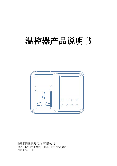
温控器产品说明书
温控器产品说明书深圳市威尔海电子有限公司电话:0755-2953 9385 传真:0755-2953 9395技术支持:田工①安装尺寸:○2连接方法:输出插座电源输入探头插孔指示灯状态说明:WORKING指示灯为工作指示灯,闪烁表示制冷或制热延时,长亮表示制冷或制热工作。
SET指示灯为设置指示灯,长亮表示在设置状态。
开启或关闭温控器:温控器通电后默认是开机状态。
在关机状态下按"POWER"键一次可开启温控器,在开机状态下,按住"POWER"键3秒以上,可关闭温控器。
◆设定控制温度:在待机状态下按"SET"键一次进入控制温度设置,按"UP"或"DOWN"键调整,按住"UP"或"DOWN"键三秒不放进入快速调整模式.再按"SET"键一次回到待机状态.※启动和关闭定时:在待机状态下按"POWER"键一次,启动定时输出,再按"POWER"键一次可关闭定时输出,屏幕交替显示OFF和当前温度。
设置控制参数:按住"SET"键三秒不放进入控制参数设置,按"UP"或"DOWN"键选择要调整的菜单,再按"SET"键一次进入相应的控制参数设置状态,按"UP"或"DOWN"键调整需要修改的控制参数,调整好后按"POWER"键退出,或系统延时5秒退出菜单代码说明:菜单代码详细说明 解释 单位 HC 制热/制冷 温控器工作模式设置 H=制热,C=制冷D 回差 开机和停机之间的温度差℃LS 设置下限 控制温度可设定的最小值℃HS 设置上限 控制温度可设定的最大值℃CA 温度较正 ℃PT 延时启动 最小开停机时间间隔 分钟AH 超高温报警 超高温报警 ℃AL 超低温报警 超低温报警 ℃AT 定时关闭输出 (选配功能) 分钟◆温控器工作模式设置:温控器可以设定为制冷模式,也可以设定为加热模式。
Fuji温控器说明书

Micro-controller XModel: PXR4/5/9Operation ManualECNO:406cTable of Contents1.Part Names and Functions (6)2.Operations (7)2-1 Parameter list (7)2-2 Basic operations (12)2-3 Parameter functions and method of settings (13)Standby setting (14)Local/remote operation setting (15)Ramp-soak control (16)Canceling the alarm latch (17)Auto-tuning function (18)Displaying ON-delay alarm or the remaining time of timers (19)Setting alarm 1, 2 and 3 (20)Upper limit of alarm 1, 2 and 3 (20)Lower limit of alarm 1, 2 and 3 (20)Key lock (21)Proportional band (22)Integral time (23)Derivative time (24)Hysteresis range for ON/OFF control (25)Cooling-side proportional band coefficient (26)Cooling-side proportional band shift (Dead band/Overlap band) (27)Output offset value (28)Anti-reset windup (28)Control algorithm (29)PV (Measured value) stable range (33)HYS (Hysteresis) mode at ON/OFF control (34)Cycle time of control output 1 (35)Cycle time of control output 2 (Cooling-side) (36)Input signal code (37)Setting the measuring range (Input range) (38)Selection °C / °F (38)Decimal point position (40)PV (Measured value) offset (41)SV (Setting value) offset (42)Time constant of input filter (43)Alarm types (44)Selecting ramp-soak patterns (47)Ramp-soak status display (48)1st to 8th target SV (48)1st to 8th ramp segment time (48)1st to 8th soak segment time (48)Ramp-soak modes (48)2Specifying control action and output direction at input burn-out (51)SV (Setting value) lower limiter (52)SV (Setting value) upper limiter (52)The time of ON-delay alarm or timer function (53)Displaying current detector input (55)HB (Set value of heater break alarm) (55)Hysteresis alarm 1, 2 and 3 (57)Options of alarm 1, 2 and 3 (58)Upper and lower limits for control output 1 (60)Upper and lower limits for control output 2 (60)Output limit types (61)Output value display (62)RCJ (Cold junction compensation) (63)Adjusting the PV (Measured value) display (0%) (64)Adjusting the PV (Measured value) display (100%) (64)DI1/2 (Digital input 1/2) operation (65)Station No. for communication (68)Parity for communication (69)Communication protocol setting (70)Re-transmission output type setting (71)Re-transmission base and span scale (72)Remote SV input (0%) adjustment (73)Remote SV input (100%) adjustment (73)Remote SV input filter constant (74)Remote SV input value display (75)Parameter display mask (76)3.Troubleshooting (77)Index (79)3PXR4Note 1: Cannot be combined with heater break alarm.( 2, 3, 6, 7, H cannot be specified on 9th digit.)Note 2: Cannot be combined with alarm (1 pc.) + heater break alarm, alarm (2 pcs.), or alarm (3pcs.).( 3, 7, F, G, H, M, P cannot be specified on 9th digit.)Note 3: Cannot be combined with RS485 + 1-point digital input.(V and W cannot be specified on 11th digit.)Note 4: In the case of control output 2, either of heater break alarm or remote SV input can be selected.(A, C, E and R on the 7th digit, and 2,3,6,7,H, D and P on the 9th digit cannot be specified.)Input signal, measurement range, and set value at the time of deliver are as follows.When thermocouple is specified: Thermocouple K, Measurement range; 0 to 400°C, Set value; 0°CWhen resistance bulb is specified: Pt, Measurement range; 0 to 150°C, Set value; 0°CWhen voltage/current is specified: Scaling; 0 to 100%, Set value; 0%For the cases other than the above, specify input signal and measurement range.Input signal of the thermocouple and the resistance bulb can be switched by key operation on the front panel.The actuating method of the control output has been set to reverse for control output 1, and to direct for controloutput 2 at the time of delivery. Note that reverse and direct actuation can be switched by key operation on thefront panel.4PXR5/9Note 1: Cannot be combined with heater break alarm.( 2, 3, 6, 7, H cannot be specified on 9th digit.)Note 2: Cannot be combined with RS485 + 1-point digital input.(V and W cannot be specified on 11th digit.)Note 3: In the case of control output 2, either of heater break alarm or remote SV input can be selected.(A, C, E and R on the 7th digit, and 2,3,6,7,H, D and P on the 9th digit cannot be specified.)Input signal, measurement range, and set value at the time of deliver are as follows.When thermocouple is specified: Thermocouple K, Measurement range; 0 to 400°C, Set value; 0°CWhen resistance bulb is specified: Pt, Measurement range; 0 to 150°C, Set value; 0°CWhen voltage/current is specified: Scaling; 0 to 100%, Set value; 0%For the cases other than the above, specify input signal and measurement range.Input signal of the thermocouple and the resistance bulb can be switched by key operation on the front panel.The actuating method of the control output has been set to reverse for control output 1, and to direct for controloutput 2 at the time of delivery. Note that reverse and direct actuation can be switched by key operation on thefront panel.56This chapter explains the part names and functions on the face panel. The face panel has the PV and SV displays, the status indicating lamp, and the setting keys, etc. Those functions are explained below. Please read and understand them before using the PXR. For details about the setting of parameters, see Chapter 2.q Lamp for control output 1Lights up while control output 1 stays ON.w Lamp for control output 2Lights up while control output 2 stays ON.e Alarm lampLights up on detecting an alarm. The alarm output is turned ON at the same time.If the optional heater break alarm is provided, the AL3lamp lights up on detecting a heater break.r PV (Measured value) displayDisplays the PV. When setting a parameter, its name appears.t SV (Setting value) displayDisplays the SV. When setting a parameter, its value appears.y SEL keyUsed to select a parameter block and a parameter, and register a set value.uUsed to change the SV , call parameters, and change pa-rameter values.i SV lampLights up while the SV is displayed in the SV display.When parameters and data are displayed, the SV lamp goes out.!0Auto-tuning/self-tuning lampFlashes under an auto-tuning or self-tuning operation.q w e Alarm lampr PV (Measured value) displayt SV (Setting value) display y SEL ukeysi SV lamp1Part Names and Functionso Auto-tuning/self-tuning lamp2OperationsThis chapter explains how to set the SV (Setting value) and the parameters for the PXR.2-1 Parameter listParameters for the PXR are classified under three blocks according to the frequency of use. The parameters of the secondand third blocks are used at initialization or when they are of absolute necessity.Note:The parameters for which * is marked with the page number in Reference page are related to Remediesof “4” on page 77.78Parameters of the second blockNote:The parameters for which * is marked with the page number inReference page are related to Remedies of “4” on page 77.Note: The parameters for which * is marked with the page number inReference page are related to Remedies of “4” on page 77.Note 1:When a customer does not specify the settings while ordering, the following settings are selected as factory defaults.Thermocouple input: Thermocouple K Measured range: 0 to 400°CResistance bulb input:Measured range: 0 to 150°CV oltage/Current input:Scaling: 0 to 100%910Parameters of the third blockNote: The parameters for which * is marked with the page number inReference page are related to Remedies of “4” on page 77.Note 2:The following settings are selected as factory defaults depending on the model you order.Seventh digit = Y model: 0Seventh digit = A model: 4Note: The parameters for which * is marked with the page number in2-2 Basic operationsJust after power-on:The display below appears just after power-on.How to switch parameters:The figure below shows the basic operations for the PXR.If it has not been used for 30 seconds, the display returns to the one just after power-on (PV/SV displayed).How to set values:key:One press increases the value by 1.Press and hold this key to increase the value fast.key:One press decreases the value by 1.Press and hold this key to decrease the value fast.How to register the set data:By pressing the SELNote that the SV (SV0) will be registered in 3 seconds without any operation.2-3 Parameter functions and method of settingsMethod of setting the SV (Setting value)[Description]•The SV is a target value for control.•Any SV that is outside of the range set in the parameters of (lower limit) and (upper limit) of the third block cannot be set. (See page 52.)[Setting example] Changing the SV from 250°C to 1195°CRelated parameters:(page 52) (page 52)Standby setting (Settings: oFF/on)[Description]•This parameter switches the control between RUN and Standby.•During standby, the control output and the alarm output stay OFF, like the standby for ramp-soak operation.•While the alarm with a hold is selected, the hold function takes effect after changing the Standby setting from ON to OFF.•is displayed during the standby for ramp-soak operations or the controller changes to the standby state in case of the occurrence of errors.•The other operations are the same as those of the ramp-soak standby.•The setting of ON/OFF for standby is saved after power-off.[Setting example] Starting the control•When the standby is set to ON during the auto-tuning,self-tuning, and ramp-soak operations, those operations will stop. (The PID constant will not be renewed.) Even through it is set to OFF later, the auto-tuning, self-tuning,and ramp-soak operations will not be re-started.•During standby, the ON-delay timer is reset. When returning to RUN from the standby state, the timer will start from the beginning.[Description]•This parameter is used to switch between local and re-mote operations.[Setting example] Switching to remote operationRelated parameters:(page 73) (page 73) (page 74) (page 75)* Local operation:Control by SV set by the keys on the front face, ramp-soak operation, SV selection determined by digital input,and SV setting via communication* Remote operation:Control by SV determined by RemoteSV inputRamp-soak control (Settings: oFF/rUn/hLd) (Option)[Description]•This function automatically changes the SV (Setting value) according to the program pattern set in advance as shown in the right line graph. Up to eight pairs of ramp-soak operation can be programmed.•The first ramp starts at the PV (Measured value) that is the one just before running the program.•The program can also automatically run at power-on (Power-on starting function). Refer to the parameter of(page 45).Related parameters:(page 48) to (page 48) to (page 48) to (page 48) (page 48) (page 47)[Setting example] Starting the ramp-soak operationRamp: the section in which the SV changes toward the target value.Soak: the section in which the SV is the target value, and remains unchanged.TM1r TM2r TM3rCanceling the alarm latch (Setting range: 0/1) (Option)[Description]•This parameter cancels the alarm latch when it is latching.[Setting example] Opening up the alarm latchRelated parameters:to(page 58)Auto-tuning function (Settings: 0/1/2)[Description][Setting example] Setting the auto-tuning operation to 1[Note]If the controller is powered off during auto-tuning, this makes the auto-tuning ineffective with each parameter of , , and unchanged. To start the auto-tuning operation, set to “1” or “2” again.•To suspend the auto-tuning, set to “0”. This makes the auto-tuning cancel with each parameter of , , and unchanged.•Once the parameters of , , and are set automatically by the auto-tuning, those parameters are stored in the controller even after it is powered off. Therefore, it is not necessary to execute the auto-tuning again.•By setting to “1” or “2” , the auto-tuning operation starts, and at the end of the tuning, will be displayed automatically to .•After the auto-tuning operation, the controller starts to operate at the automatically set values of , , and .•A decimal point at the right end of the SV display flashes during auto-tuning.•There are two codes for AT:Setting code [1]:SV standard typePerforms the auto-tuning based on the SV.Setting code [2]:Low PV typePerforms the auto-tuning based on the SV-10%FS.[Note]Since ON/OFF control is performed during auto-tun-ing, overshoot against the SV may occur. To reduce the overshoot, execute the auto-tuning operation with the setting code [2] (Low PV) selected.•The auto-tuning can be executed both just after power-on and in a control or stable status.Related parameters:(page 22) (page 23) (page 24) (page 28) (page 26)Displaying ON-delay alarm or the remaining time of timers(unit: seconds) (Option)[Setting example] Displaying ON-delay alarm or the remaining time of timers[Description]•These parameters display the remaining time of Timers 1, 2 and 3.•The remaining time of the ON/OFF-delay timer is counted down. When the counter shows , the alarm relay is closed.•During count-down, if the PV changes to the value of the temperature at which the alarm is set to OFF, or if “DI”for the timer is set to OFF, the counter is reset, and thealarm relay is opened.Remaining time (seconds)•display parameter[Setting example] Setting the operation value of alarm 2 to -10°C[Description]•These parameters are used to for settings of alarm 1, 2and 3.•When the alarm type (,or ) is set to 0 to 15, alarms 1, 2 and 3 (, and ) can be set.•When the alarm type (,or) is set toany value other than 0 to 15, the upper and lower limitsof alarm 1, 2 and 3 (, , , , ,) can be set.[Note]Setting codes (12 to 15) cannot be selected in alarmtype 1 and 3 ( / ).Related parameters:, , (page 44), , (page 57), , (page 53),,(page 58)(Setting range:Absolute value alarm: 0 to 100%FS Deviation value alarm: -100 to 100%FS )(Option)}Setting alarm 1, 2 and 3Upper limit of alarm 1, 2 and 3Lower limit of alarm 1,2 and 3[Setting example] Setting the key lock to “2”Key lock (Setting range: 0−5)[Description]•This parameter makes the set values of parameters unchangeable. However, the parameter name and the set values can be displayed.•To reset the key lock, change to .•Even when the key lock is set, control and alarm functions can operate properly.•There are six levels of the key lock::Unlocked (reset):All settings are unchangeable from the controller, but changeable via communication.:Only the SV is changeable from the controller, and all settings are changeable via communication.:All settings are changeable from the controller, but unchangeable via communication.:All settings are unchangeable from the controller or via communication.:Only the SV is changeable from the controller, but all settings are unchangeable via communication.Proportional band (Setting range: 0.0 to 999.9% of the measured range)[Description]•To select the ON/OFF control (two-position control), setto 0.0. It is not necessary to set and .• can be automatically set by the auto-tuning operation.•When is too small, control will be unstable, and whenis too large, the response will be delayed.[Setting example] Changing the proportional band from 5.0% to 15.0%•Set the hysteresis of the ON/OFF control (two-positioncontrol) in the parameter.•If auto-tuning is run after the ON/OFF control is selected,the ON/OFF control changes to the PID control. To keep the ON/OFF control selected, do not execute the auto-tuning.Integral time (Setting range: 0 to 3200 seconds)[Description]• can be set automatically by the auto-tuning operation.•can also be set manually.[Setting example] Changing the integral time from 240 seconds to 600 seconds•When is set to 0, the integral operation does not start.•When is set to 0.0, this makes the setting of ineffec-tive.Derivative time (Setting range: 0.0 to 999.9 seconds)[Description]• can be set automatically by the auto-tuning operation.•can also be set manually.[Setting example] Changing the differential time from 60.0 seconds to 50.0 seconds•When is set to 0, the differential operation does not start.•When is set to 0.0, this makes the setting of ineffective.Hysteresis range for ON/OFF control (Setting range: 0 to 50%FS)[Description]•To select the ON/OFF control (two-position control), setto 0.0. It is not necessary to set and .•When the hysteresis range (Range of ON/OFF control) is too small, the output may switch the ON/OFF frequently.(This may affect the life of the device to be controlled,especially when contact output is selected.)•The unit of the set value of this parameter is ºC or ºF (engineering unit). The setting range varies according to the measured range of input.[Setting example] Changing the hysteresis range from 1˚C to 35˚C[Ex] Input Thermocouple K :At measured range of 0to 400 ºC, the setting range is 0 to 200 ºC.Resistance bulb :At measured range of 0to 150 ºC, the setting range is 0 to 75 ºC.Related parameters:(page 22)(page 34)Cooling-side proportional band coefficient (Option: Available for DUAL output only) (Setting range: 0.0 to 100.0)[Description]•This parameter is used for setting the cooling-side pro-portional band. (See the figure below.)[Setting example] Changing the cooling-side proportional band coefficient from 1.0 to 2.5•Before setting the cooling-side proportional band, set the heating-side proportional band to an optimum value. To select the two-position control for the cooling side, setto 0.0.Output•When is set to 0.0 and is set to 0.0 in the dualoutput type, the cooling output is as shown in the figure below. The hysteresis is fixed at 0.5%FS.Cooling-side proportional band=Proportional band (P)2× Coefficient Ex) When making the proportional band of 10% of thefull scale with the proportional band (P) being 50%:10% = × Coefficient50%2Consequently, the coefficient is 0.4.Related parameters:(page 25) (page 22) (page 27)Heating output (Output 1)ON 0.5%0.5% ONCooling output (Output 2)SVPVCooling-side proportional band shift (Dead band/Overlap band) (Option: Available for DUAL output only) (Setting range: -50.0 to +50.0)[Description]•This parameter is used for shifting the cooling-side pro-portional band from the set value. (See the figure below.)[Setting example] Shifting the cooling-side proportional band by 2.0•Related parameters:(page 22)•When is a positive value, it is called the "Dead band",and when it is a negative value, the "Overlap band".•Since the unit of is same one used for MV [%], if you want to set in the unit of deviation [%], must be converted using the equation below.OutputMV=50%Ex) When making a dead band with a deviation of1.0 [%] from the SV while the proportional band (P) is 5.0%:DB [%] = 1.0 × = 20 [%]1005.0100PDB [%] = Deviation × [%]Consequently, set the parameter to 20 [%].Output offset value (Setting range: -100.0 to 100.0 %)Anti-reset windup (Setting range: 0 to 100%FS)[Description]•The anti-reset windup ( ) is automatically set to anoptimum value by the auto-tuning operation.By setting , the amount of overshoot can be adjusted.[Note]By making use of the fuzzy control system equipped withPXR, the amount of overshoot can be minimized withoutsetting and .[Setting example] Changing the anti-reset windup from 60˚C to 80˚C.PVControl algorithm (Settings: PID/FUZY/SELF)[Description]•This parameter is used for selecting PID control, FUZZY -PID control, or PID control with self-tuning.•To select the PID control or FUZZY-PID control, it is necessary to set the parameters of , ,, and manually or by the auto-tuning in advance.[Setting example] Changing the control system from PID to FUZZY•For the ON/OFF control (Two-position control), select the PID control and then set to 0.0. For detailed infor-mation, refer to (page 22).•Refer to the next page for the PID control with self-tuning.[Self-tuning]1Function:With the self-tuning function, PID parameters are automatically re-optimised depending on the actual condition of device to be controlled and the setting temperature (SV).2How to execute:Follow the procedure shown below to set and execute the self-tuning. The self-tuning starts to run at the appropriate conditions. (See page 31)*1: How to set the parameter of :*2: Display during self-tuning is shown below:3Conditions under which the self-tuning runs:q At power-on:The self-tuning runs when all of the following conditions are met.•The SV that appears at power-on is not the same one when the , , , and were set previously. (i.e. the , , , and set by the self-tuning, auto-tuning, manual setting, and writing by communications tools at previous time)•The (SV-PV) at power-on is larger than (the value of × input range) or (the set value of ).w When the SV is changed:The self-tuning runs when all the conditions below are met.•The changed SV is larger than the SV that was set when the , , , and were selected previously.•The changed amount of the SV is larger than 0.•The changed amount of the SV is larger than (the set value of × input range) or (the set value of ).e When output becomes unstable:The self-tuning runs when control becomes unstable and the hunting of the operating output (MV) occurs. (The self-tuning runs only once as long as the SV is not changed.)r When the control standby mode is cancelled:The self-tuning runs by the same reason as "q At power-on" are met.* Only when the PXR is set to standby mode at power-on.4Conditions under which the self-tuning does not run:q During control standby modew During two-position control (Parameter of = 0)e During auto-tuning operationr During ramp-soak operationt Error display ( or is displayed.)y During dual output (The set value of the parameter of is larger than 4.)u When setting the parameters of , ,, and manually (including the setting written by communications tools)5Conditions under which the self-tuning is suspended:q At the condition described in 4shown abovew When the SV is changed during self-tuning operatione When the self-tuning operation can not be completed within approx. 9 hours6Cautionq Once the PID constant is set, the self-tuning does not operate at next power-on as long as the SV is not changed.w For an accurate tuning, be sure to power on the device to be controlled before or at the same time as the PXR is powered on. If the PXR has to be powered on first for reasons of the system configuration, perform the auto-tuning with the PID or FUZZY control.e If the device to be controlled is powered on under temperature change (especially when it rises), accuratetunings can not be performed. Be sure to power on the PYX when the temperature of device to be controlled is stabilized.r The self-tuning does not run for cooling system control under Direct Action output (Parameter = 2 or 3). t In case the control is not stable after performing the self-tuning, change the algorithm to the PID or FUZZY control and perform the auto-tuning.7Reference [About the self-tuning method]The PID constant is calculated in one of the following two methods.The method is selected automatically depending on the characteristics of the device to be controlled.• Step response method• Limit cycle methodThe following figures show the operations at power-on and changing the SV, and under unstable control. q Operations at power-onw Operations at changing the SVe Operation under unstable controlPV (Measured value) stable range (Setting range: 0 to 100%FS)[Description]•Self-tuning logic recognizes that control is stable if PV is staying within the SV ± .[Setting example] Changing the PV stable range from 2 to 3•It is not necessary to set this parameter under normal con-ditions.HYS (Hysteresis) mode at ON/OFF control (Settings: oFF/on)[Description]• This parameter is used for selecting the hysteresis opera-tion mode at ON/OFF control.• Default setting: ONStarts the ON/OFF control at the values ofSV+ and SV- .Starts the ON/OFF control at the values ofSV and SV+HYS, or SV and SV-HYS.HYS 2HYS 2::[Setting example] Setting the hysteresis mode to ONCycle time of control output 1 (Setting range: 1 to 150 seconds) [Description]•This parameter is applicable for to the contact output and SSR-driving output.•While input is within the proportional band, output changes between ON and OFF in cycles. These cycles are called cycle time.For contact output:The higher the frequency of output is, the more precise the control becomes. However a high frequency of out-put may shorten the life of the contacts and the device to be controlled. Be sure to adjust the proportional cycles considering controllability and the life of the device and the contacts.Typical: 30 secondsFor SSR-driving output:Use in short cycles if there is no problem with the device to be controlled.Typical: 1 to 2 secondstimetime[Setting example] Setting the cycle time from 30 seconds to 20 seconds•Do not set this parameter to "0".Cycle time of control output 2 (Cooling-side)(Setting range: 1 to 150 seconds) (Option: Available for DUAL output only) [Description]•By this parameter is set, the cycle time of control output 2.•While input is within the proportional band, outputchanges between ON and OFF in cycles. These cyclesare called cycle time.[Setting example] Setting the cooling-side cycle time from 30 seconds to 20 secondstimetimeFor contact output:The higher the frequency of output is, the more precisethe control becomes. However a high frequency of out-put may shorten the life of the contacts and the device tobe controlled. Be sure to adjust the proportional cyclesconsidering controllability and the life of the device andthe contacts.Typical: 30 seconds•Do not set this parameter to "0".Input signal code (Setting range: 0 to 16)[Description]•This parameter is used for selecting input signals. Input signal varies depending on the sensors (2 types below).Set a code that corresponds to the sensor you use.Type I :Thermocouples (9 kinds of signals)Resistance bulbs (1 kind of signal)Type II :V oltage, current•Input signals can be selected within the same type. It is impossible to select input signals of a different type.•For type II, to change from the voltage input to the cur-rent input, connect the supplied resistance of 250Ω be-tween terminals !7 and !8 (in the case of PXR4), and between terminals #5 and #6 (in the case of PXR5/9), in addition to changing the code.When changing from the current input to the voltage in-put, remove the resistance of 250 Ω as well as changing the code.[Note]After changing the codes, power off the PXR, and then power it on again.[Setting example] Changing from thermocouple K to thermocouple T in T ype I•Input signals and codes q Input signals code table。
