风电说明书
2.0MW风力发电机组产品说明书_A版_ (1)

风力发电设备操作指南说明书

Studies on the Screening Method of the Outliers of Wind Power inWind Power GenerationFeng GangElectric Power Dispatching Center State Grid ZhouShan Power Supply CompanyZhejiang, ChinaLiu YaoFaculty of Science Beijing Forestry UniversityBeijing, Chinae-mail:*****************Li HongjieFaculty of Science Beijing Forestry UniversityBeijing, Chinae-mail:******************Liu LihuaFaculty of Science Beijing Forestry UniversityBeijing, Chinae-mail:****************Fei JianpingElectric Power Dispatching Center State Grid ZhouShan Power Supply CompanyZhejiang, ChinaWang DongElectric Power Dispatching Center State Grid ZhouShan Power Supply CompanyZhejiang, ChinaYi LeiFaculty of Science Beijing Forestry University Beijing, Chinae-mail:***************Wang HongqingFaculty of Science Beijing Forestry UniversityBeijing, Chinae-mail:*******************Abstract—Through the analysis of wind power, reasonably adjusting the power is the key to stable operation of wind power generation. In this paper, first the wind power curve is studied on the basis of the least square method, so that the variation rules of wind power can be determined, and on the basis of a given reasonable threshold, the outliers and abnormal coefficient can be identified.secondly, we expand the data dimension and calculating the 15-day average of every time . Thus there is a new data set , and using the same method above can quickly locate the outliers existing range. Finally, time series iteration method is used to establish outliers identification model, and the points of wind power are found. Finally, the actual value on the abnormal point based on the outlier fitting model is estimated. Thus effective regulation of wind power can be achieved.Keywords-The least square method; time series iteration method; outlier identification;The outlier fitting model; MATLABI.I NTRODUCTIONThe development and utilization of wind energy began in the 1970's,Some developed countries, such as America and Western Europe had to find new energy to substitute fossil energy under the pressure of oil crisis. They began to build wind farms and grid generation from 1980's, and then the wind energy became a new power energy. From the middle of 1980's, the wind power technology has made rapid development in the world. Wind power can not only reduce emissions of the main greenhouse gas, but also meet the growing global demand for energy[1].The running data of wind farm is collected through the SCADA system. It may be interfered during the data collection, transmission or conversion, and because of the scheduling mechanism control, maintenance and other factors will also result in abnormal actual power of wind farm. Due to scheduling instruction, fan operation and other auxiliary information is difficult to obtain, the abnormal data cannot be effectively screened. Thus, choosing suitable methods and effectively eliminating the outliers in the data can make the wind power play to the best effect.At present, research on the accuracy of wind power system data is roughly divided into two kinds:(1)a data validation method based on Neural Network[2],using parameter prediction model predict parameters; But theInternational Conference on Logistics Engineering, Management and Computer Science (LEMCS 2014)neural network method always turns the feature of problems to digital, all reasoning to numerical calculation ,and the result is bound to the loss of information. (2)Outlier detection based on wavelet analysis, in Literature [3] the high frequency components and low frequency components of the continuous data stream are separated, then the outliers in the data are found by combining with clustering method; however, once the wavelet function is selected, the property is fixed in the wavelet analysis, then it's difficult to accurately approximate the local features of the signal at different scales, there may be loss of original time domain features. In this paper, the least square method to fit the data of wind power is used to determine the abnormal data and abnormal coefficient by formulating a reasonable threshold; in addition, a new method ——the iterative algorithm in the time series analysis is used to distinguish the abnormal values. It does not only keep the time and domain characteristics and the hidden information of the original data, but also increases the fitting degree, improves the accuracy, and reduces the searching time of abnormal values. II.DATA FITTING BASED ON LEAST SQUAREMETHODSupposing that the error ),,...,1,0()(*m i y x S i i i =-=δTm ),...,,(21δδδδ=,and )(),...,(),(10x x x n ϕϕϕ islinearly independent functions in ],[b a C ,then we canfind a function)(*x S in )}(),...,(),({10x x x span n ϕϕϕϕ=,and the )(*x S meets the condition of∑∑∑=∈==-=-==mi iix S mi i i mi i y x S y x S 02)(02*222)1(])([min])([ϕδδWhere .)()(...)()()(1100m n x a x a x a x S n n <+++=ϕϕϕ This is the method of least squares in curve fitting [4]. A. Establish ModelWe take a data set ),...,2,1,10)(,(m i y x i i =, containing m+1 elements, in which i x is time and i y ispower. Thenweusethepolynomialofn n n x a x a x a a x p ++++=...)(2210, the approximatingfunction)(i i x f y =. The approximating method is tomake the distance minimum based on the discrete norm of ∑=-=mi i n i n x p y a a a d 0210))((),...,,(. Therefore we get thelinear equation about n a a a ,...,,10:nn n n n n n n n t a s a s a s t a s a s a s t a s a s a s =+++=+++=+++++211011*********....................................Where n i x y t n i x s mi k i i km i k i k ≤≤=≤≤=∑∑==0,;20,0. Supposing thatthe threshold we set before is σ,then we decide i y is outlier ifi y satisfiesσ>-i j Y x p )(.B. Prove and AnalysisThe data originates from the Jiangsu coastal wind power plants, a total of 34848 groups of wind monitoring data from December 1, 2008 to March 31, 2009, provided by the Electric Power Research Institute. Due to the large amount of data, we use the grouping method to simplifying the process, and also improve the accuracy of the model. The specific steps are as follows:(1)Take 150 data to fit in turn, that is, the first group is the data from 1st to the 150th , the second group is from the 151th to the 200th , and the third one is from the 101th to the 250th , and so on .There are 233 groups.(2)Use least square method to construct 9 times polynomial approximation on the 150 data we take, where m=9, n=9.(3)Because the middle part of the curve is fitted the best, we take the middle 50 data of the first group (that is 51-100) and the middle 50 data of the second group (that is 101-150) end to end ,and so on ; (4)As that, until the end of the data.After that we use matlabR2010a ,operate all data by adopting the method above ,the following is partly fitting results (Fig .1):Figure 1. 1-150 data fitting imageAt the same time, we get the coefficient matrix of the step function, thus the final 9 order approximation polynomial is:98765432)1436.1()1295.8()0940.2()0734.3()0556.2(0011.00209.01665.02756.19332.64x E x E x E x E x E x x x x y -+--+-+---+-+-+=The residuals chart of the original data and fitting data:Figure 2.Due to the large amount of data (all data is 34848),we intercept the fitting image of the 5000th to the 7000th ,as following :Figure 3.Analysis :Using the 9 order polynomial fitting achieves the best effect, which is more than 90%.By the residuals chart of the data, we can find the residual curve fluctuates around 0, and the relative data fluctuation is very small. This can also illustrate that the fitting degree is very good.III. INSPECTION OF OUTLIERS BASED ONLEAST SQUARE METHOD Using all of the original data to search the outliers is a method based on one-dimensional space. We expand the dimension of the data. We use the average of 5 days (15 days) data instead of the original data at each time to form a new dataset. Then using the above method can be more quickly to determine the interval of the outliers.In this case, we suppose that for data of each time, the arithmetic average of five data: the two data prior to this data, the two data next to this data and this data take place of the original data of each time. For example, we render the data of 100th time 100y a new value 100Y ,1009899100101102()/5Y y y y y y =++++to replacethe original data. Then, apply previous Least Square Method to analyze new data, where in the same way, denote σ as threshold value and assume that if i Y satisfies ()j i p x Y σ->, there are outliersbetween2112,,,,i i i i i y y y y y --++.In the same way, we can use the arithmetic average of fifteen data to replace the original data. And in this case, if i Y satisfies ()j i p x Y σ->, we assume that there are outliers between these fifteen data which are near i Y , and this is the range of outliers that we find.Applying this method, inspect data 101st -250th. Figure 4 shows the figure of new data and fitting curve. Table 1 shows the outliers where we assume that σ=0.1 and use arithmetic average of fifteen data to replace the original data.Figure 4.The figure and table show that the abnormal coefficients of time 178th to 184th are much big, which means that it is very possible that outliers exist between their overlap parts. On the other, the abnormal coefficients of 127th to 129th are also big, which means it is also possible that outliers exist between their overlap parts.IV. INSPESTION OF OUTLIERS BASED ONITERATION METHOD [5] Before you begin to format your paper, first write and save the content as a separate text file. Keep your text and graphic files separate until after the text has been formatted and styled. Do not use hard tabs, and limit use of hard returns to only one return at the end of a paragraph. Do not add any kind of pagination anywhere in the paper. Do not number text heads-the template will do that for you.Finally, complete content and organizational editing before formatting. Please take note of the following items when proofreading spelling and grammar:A. Mathematic Model of OutliersAmong the on-line monitoring data of wind power, according to their properties and generating mechanisms, outliers can be classified into 2 kinds [6]. 1) Additional outliersThis kind of outliers is isolated. Normally, these outliers generate because equipments have been interfered externally or disturbed by themselves. Their appearance won’t affect adjacent observed data. As for time series which is based on on-line monitoring value, this kind of outliers is nonessential and they are not related to internal structure of time series.2) New Informational OutliersThis kind of outliers will appear aggregated because they will affect a series of observed data through correlation of time series. And the generating mechanism of this kind of outliers is that the structure of dynamical system has changed so that the internal structure of time series will change abnormally and generate these outliers.t Z is observed series, and t X is a series without outliers 。
Rutland 1200 风电Converter 操作指南说明书
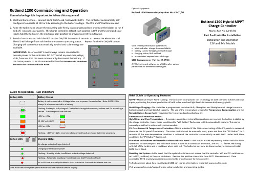
Rutland 1200 Commissioning and OperationCommissioning– it is important to follow this sequence!1. Electrical Connection— connect BAT2 first if used, followed by BAT1. The controller automatically self configures to operate at 12V or 24V according to the battery voltage . The WG and PV buttons are red.2. Raise the turbine and secure the mounting pole firmly in an upright position or release the blades to run if tied off. Uncover solar panels. The charge controller default start position is OFF and the wind and solar inputs hold the turbine in the electronic stall position to prevent current from flowing.3. Switch On— Press and hold the WG turbine ON/OFF button for 3 seconds to release the electronic stall. The LED will change from solid red to the current operating status. Repeat for the PV ON/OFF button. Charging will commence automatically as wind and solar energy are available. IMPORTANT: In service BAT1 must always remain connected to provide power to the controller. DO NOT install any switches, relays, VSRs, fuses etc that can even momentarily disconnect the battery. If the battery needs to be disconnected follow the Procedure to Shutdown and Start the Turbine and Solar Panel.limited. Turbine speeds are reduced.Button LEDsRutland 1200 Hybrid MPPTCharge Controller Marlec Part No: CA -07/01Part 2—Controller InstallationInstallation and Operation 12V and 24V ModelsBrief Guide to Operating FeaturesMPPT —Maximum Power Point Tracking. The controller incorporates this technology on both the wind turbine and solar inputs, optimising the power production of both in low wind and light levels to increase daily energy yields.Multi -Stage Charging —The controller is programmed to deliver Bulk, Absorption and Float phases of charge to ensure batteries reach and maintain full capacity. The use of the temperature sensors for Temperature Compensation and the Remote Battery Sensor facility maximise this feature and prolong battery life. Electronic Stall Protection Modes:High Winds and Over Temperature— If excessive currents or internal temperatures are reached the turbine is stalled by the charge controller. Under these conditions the “WG Button ” flashes red until it automatically restarts. This can be manually re -set but is not normally recommended.PV Over -Current & Temperature Protection—This is activated if the 20A current rating of the PV panels is exceeded, downsize the PV panel if necessary. The solar control must be manually reset, press and hold the “PV Button ” for 3 seconds. If the over -temperature condition is activated the controller automatically re -sets itself. Under both these conditions the “PV Button ” flashes red.Procedure to Shutdown and Start the Turbine and Solar Panel - Each button is used respectively to start and shutdown operation. To activate press and hold each button in turn for a continuous 3 seconds , the WG LED flashes red during soft stall of the turbine and is shutdown when solid red. The batteries may now be disconnected, to reconnect install BAT2 first if fitted.Resetting the System—In the event that the system has to be re -set ensure that the controller WG and PV switches are set to OFF , solid red, so they are shutdown. Remove the positive connection from BAT 1 then reconnect. Once connected BAT 1 must always remain connected to provide power to the controller.To find out more about how your Rutland 1200 can charge other battery types visit Visit /support to see video installation and operating guides.Optional Equipment:Rutland 1200 Remote Display –Part No: CA -07/02View system performance parameters: • wind and solar charge Amps and Watts • battery 1 and 2 Voltages and % of charge • charging status; Bulk or Float• accumulated ampere hours of charge 1200 Reprogrammer –Part No: CA -07/04A PC link wire and software on a USB to alter various parameters for different battery types.xInstall The Controller and CablesDuring installation the turbine must be restrained from turning and PV panels must be covered.1. Fix the Rutland 1200 Charge Controller to a vertical surface as shown using 4 screws in a weatherproof environment. See H2. Install the selected power cables from the turbine and solar panels to the controller. Strip back 10mm of insulation on all power cables. The turbine 3 phase cables have no polarity to observe but ensure solar panels are correctly connected + and -3. Prepare cables to make a direct connection from the controller to the batteries but DO NOT connect to the battery at this time. The controller is internally fused but note that reverse polarity connection to the battery will cause permanent damage. IMPORTANT: DO NOT install any switches, relays, VSRs, fuses etc in the cables that can even momentarily disconnect the battery. Avoid additional connections or terminations in the battery lines. Any interruption to the BAT 1 power supply whilst wind or solar charging will damage the controller.4. Installation of sensing wires is highly recommended for most efficient charging through the bulk, absorption and float phases. Important information about sensing wires: Remote Temperature Sensor — When installed the temperature compensation feature is activated and voltage regulation settings are automatically adjusted to ensure batteries are fully charged whatever the local temperature. Temperature compensation is disabled if not fitted. Remote Battery Voltage Sensing Wires —if not connected the BAT1 and BAT2 terminal voltage is used for sensing the battery voltage. Any voltage drop associated with long cable distances (>1.5m) will reduce the accuracy of the charging regime.ABCGFButton258mm164m m68m m Rutland 1200 Controller Installation and Electrical ConnectionRead in conjunction with Part 1 Rutland 1200 Turbine Installation manual. Find more information at DE。
风力发电设备联合仿真系统使用手册说明书

风力发电设备联合仿真系统使用手册沈阳华人风电科技有限公司二零一六年一月未经沈阳华人风电科技有限公司事先书面许可,本手册的任何部分不得以任何形式进行增删、改编、节选、翻译、翻印或仿制。
本手册的全部内容沈阳华人风电科技有限公司可能随时加以更正,此类更正将不另行通知。
具体应用以软件实际功能为准©本手册的著作权属于沈阳华人风电科技有限公司版权所有•翻制必究2016年1月第9次印刷本书中涉及的其他产品商标为相应公司所有。
在中华人民共和国印制。
目录目录 (3)第1章系统概述 (4)1.1软件简介 (4)1.2主要功能 (4)1.3安装指南 (5)1.3.1软件安装 (5)1.3.2软件卸载 (9)1.3.3加密锁功能简介与驱动安装 (10)1.3.4辅助插件的安装 (10)1.3.5 安装 (14)1.3.6动态链接库文件使用 (16)第2章使用说明 (19)2.1仿真控制 (20)2.1.1 “启动”/“关闭”仿真程序 (20)2.1.2仿真进程控制 (20)2.1.3显示比例控制 (21)2.1.4“暂停”/“继续”仿真程序 (21)2.1.5电网全部“导通”/“断开” (21)2.1.6批量“启动”/“关闭”机组 (21)2.1.7仿真数据初始化 (22)2.2电场监控 (26)2.2.1风场环境仿真 (26)2.2.2风电场电气系统仿真 (29)2.2.3机组变流参数仿真 (37)2.2.4风电数据采集与分析 (38)2.3设备监控 (43)2.3.1机组发电系统仿真 (43)2.3.2机舱温度场仿真 (45)2.3.3风电机组安全监控 (47)2.3.4机组传动系统仿真 (49)2.4运维培训 (50)2.4.1风电机组定检培训 (50)2.4.2电气设备操作培训 (56)第1章系统概述1.1软件简介风力发电设备联合仿真系统是一款可实现风电场及风力发电设备全范围仿真的大型软件系统,囊括了风电机组及其风轮系统、发电系统、传动系统、控制系统、安全链等子系统的数学模型,并可实现各子系统运行的协调控制。
禾望电气风力发电系统产品手册说明书
风力发电系统产品手册领先业绩卓越品质自主产权先导技术业绩分布地点:河北东辛营河北崇礼西桥梁河北大囫囵河北张家口河北御道口河北沧州河北唐山吉林大安红岗子吉林安广青海共和青海德令哈青海格尔木新疆喀什英吉沙新疆伊吾内蒙通辽义和内蒙宝龙山甘肃金昌甘肃兰州宁夏宁东宁夏固原宁夏中卫广东湛江广东连州广东广州广东东莞贵州赫章河南三门峡河南西峡广西富川湖南临武湖南隆回湖南桂阳辽宁沈阳辽宁抚顺黑龙江大庆黑龙江肇源黑龙江绥滨山东文登山东莱州山东平度山东烟台江苏扬州江西九江四川德昌陕西榆林甘肃瓜州甘肃玉门甘肃酒泉云南泸西云南寻甸云南陆良云南丘北云南洱源云南剑川山西天镇山西左云山西忻州山西朔州浙江玉环浙江宁波浙江杭州江苏无锡江苏苏州.....内蒙二连浩特内蒙化德内蒙海拉尔内蒙巴彦淖尔内蒙满洲里内蒙乌兰察布内蒙乌拉特后旗内蒙赤峰内蒙辉腾梁内蒙锡林浩特内蒙朱日和内蒙呼和浩特辽宁阜新辽宁营口辽宁彰武辽宁法库盐城苏州上海制造基地营销服务中心制造基地西北西南华南华东东北华北业绩点150+业绩点110+业绩点110+业绩点460+业绩点40+业绩点290+东莞北京深圳>>业绩分布风电产品电网主断路器网侧熔断器主接触器网侧滤波器网侧变流器机侧变流器机侧滤波器DFIGG定子接触器主动Crowbar3333产品概述风能是一种清洁的、可再生的能源,风力发电作为风能最重要的利用形式,有着良好的环境效益和经济效益。
在风力发电机系统中,风力发电变流器将风力发电机输出的频率和幅值变化的电能通过交-直-交转换,转化为恒压恒频的电能馈送到电网,实现风力发电机的变速恒频控制。
风力发电变流器可分为双馈变流器、全功率变流器、中压风电变流器等,分别配合双馈电机、低压永磁/电励磁电机、中压永磁电机等使用。
产品系列名 称适配机型功 率应用环境配置风能产品双馈变流器风冷 1.5MW~6.0MW标准型高原型低温型沿海型海基型水冷全功率变流器低速永磁 1.0MW~10.0MW中速永磁高速永磁电励磁高速异步机中压风电变流器永磁电机5.0MW~10.0MW沿海型海基型>> 风力发电变流器概述风 电 产 品—变 流 器 产品技术参数技术参数>> 双馈变流器-风冷通用型① 满足1.3倍高电压运行② 其它频率范围详询禾望电气③ 4000m以上解决方案详询禾望电气* 以上①②③通用于整个双馈变流器系列性能特点高可靠性设计:耐受严酷的气候、振动等工作环境丰富、灵活的对外接口:完美匹配各类电机和主控系统领先的控制技术:主动适应恶劣电网,保障用户投资收益高功率密度:小型化部件和模块化设计,可快速安装和维护风冷系统,维护方便、简单,性价比高,特别适用于陆地高海拔、高温、低温等环境完善的系统监控和故障诊断:hopeInsight监控软件可实现单台变流器的远程监控与故障诊断,hopeView网络监控系统可方便实现风场变流器的组网和监控以及变流器有功、无功的远程调度2.0MW2.5MW3.2MW工作电压552V~759V工作频率(网侧)47.5Hz~52.5Hz / 57Hz~63Hz额定电流2000A 2417A 2761A 网侧最大持续电流420A 550A 700A 网侧过载电流(1min/10min)540A 600A 770A 机侧最大持续电流800A 1000A 1250A 机侧过载电流(1min/10min)880A1100A 1400A 电网电压谐波耐受度≤5%电网电压不平衡度耐受度≤8%整机效率>97%噪声<70dB工作温度环境温度:-40℃~+50℃(45℃~50℃降额)储存温度-40℃~+70℃海拔常规型:≤2000m,高原型:2000m~5000m冷却方式水冷防护等级IP54低压穿越满足国标,欧洲E.ON2006外形尺寸W*H*D(mm)2700*2200*640技术参数>> 双馈变流器-水冷型技术参数丰富、灵活的对外接口:完美匹配各类电机和主控系统领先的控制技术:主动适应恶劣电网,保障用户投资收益高可靠性设计:耐受严酷的气候、振动、盐雾等工作环境高功率密度:小型化部件和模块化设计,可快速安装和维护水冷系统,防护等级高,可靠性高,特别适用于高盐雾、高污染和高湿度环境完善的系统监控和故障诊断:hopeInsight监控软件可实现单台变流器的远程监控与故障诊断,hopeView网络监控系统可方便实现风场变流器的组网和监控以及变流器有功、无功的远程调度性能特点2.0MW2.5MW3.2MW5.0MW工作电压552V~759V工作频率(网侧)47.5Hz~52.5Hz / 57Hz~63Hz额定电流2000A 2417A 2975A 4686A 网侧最大持续电流420A 550A 700A 1020A 网侧过载电流(1min/10min)640A 600A 770A 1200A 机侧最大持续电流800A 1000A 1250A 1940A 机侧过载电流(1min/10min)880A1100A1400A2140A电网电压谐波耐受度≤5%电网电压不平衡度耐受度≤8%整机效率>97%噪声<70dB工作温度环境温度:-40℃~+50℃,入水口水温:+5℃~+55℃(50℃~55℃降额)储存温度-40℃~+70℃海拔常规型:≤2000m,高原型:2000m~5000m冷却方式水冷防护等级IP54低压穿越满足国标,欧洲E.ON2006外形尺寸W*H*D(mm)2300*2000*640(一字型)1650*2200*1300(背靠背型)2300*2000*640(一字型)1650*2200*1300(背靠背型)3600*2200*640(一字型)参数功率等级参数功率等级水冷机由变流器自主控制,无需外部参与,配合逻辑更优,变流器可以及时响应水冷机异常状况统一的后台监控软件,可以实时监控水冷机运行状况及故障记录等,统一客服巡检>>全功率变流器原理简述禾望电气HWFP069系列全功率变流器用于风力发电系统中与永磁、电励磁同步发电机或者高速异步发电机配套使用,变流器由机侧变换器和网侧变换器组成,两者通过直流母线连接。
联合动力15MW机组说明书(1)

1.5MW风电机组说明书编制:校对:审核:批准:目录一、机组简介 (4)1.1总体技术参数介绍 (4)二、机组部件介绍 (8)2.1叶片介绍 (8)2.2轮毂及变桨系统简介 (8)2.3传动链系统 (9)2.4偏航系统 (10)2.5液压系统简介 (11)2.6齿轮箱系统 (14)2.7发电机系统 (16)2.8滑环系统 (18)2.9电气控制系统 (19)2.10变流器简介 (24)2.11 监控系统 (25)2.12风况检测装置 (26)2.13防雷系统 (26)三、机组运行状态说明 (27)3.1待机状态 (28)3.2启动状态 (29)3.3运行状态 (30)3.4并网发电状态 (31)3.5停机状态 (32)3.6维护状态 (34)3.7机组运行及注意事项 (35)一、机组简介1.5MW风力发电机组是由国电联合动力技术有限公司与德国Aerodyn公司联合设计,它采用三叶片、上风向、水平轴、双馈异步发电机、主动电变桨矩、变速恒频逆变器并网技术,具有通用性强、功率曲线先进、结构成熟、运行可靠等优点,同时在发电机、齿轮箱、轴承等关键部件上采用了最新设计,单机容量最适合中国目前的环境及安装使用条件。
国电联合动力技术有限公司在设计之初就提出了‘差异化,系列化’的设计思路,充分考虑中国实际风资源状况,在德方设计的防风沙机型基础上,发挥联合设计优势,进行产品系列化设计。
根据中国不同风场类型,设计了分别适用于IEC2A,IEC3A和IEC2A+,IEC3A+等的冷态,常温,防风沙的系列风机,根据机组叶轮直径不同分为:UP77、UP82、UP86三种类型。
1.1总体技术参数介绍续前表:二、机组部件介绍2.1叶片介绍1.5MW风电机组所用的叶片基体材料是有高性能的低粘度环氧树脂加热固化而成,具有粘接强度高、韧性好、耐腐蚀、耐疲劳性好,断裂延伸率高的特点,能够与增强材料良好的匹配,满足叶片的耐疲劳性能要求。
Primus Wind Power WCP-D风电机数字控制面板说明书

1INSTRUCTION MANUAL - MODEL WCP-DAIR Wind Turbine Digital Control PanelThe wind generator digital control panel is fully calibrated and ready for installation. Please follow the instructions below for proper indoor installation. This manual covers 4-32 Amp rated WCP-D which is designed to operate with 12-48 VDC nominal battery banks.OVERVIEW:This control panel is designed to be installed indoors protected from weather. Installation requiresdrilling holes into the base of the plastic enclosure to allow for mounting and wiring.The Circuit Breaker switch is used to turn on and off the wind turbine control panel as well as provide protection in case of a major fault. The RUN-STOP toggle switch controls the operation of the wind turbine. In the RUN position, it allows the wind turbine to operate and produce power while in the STOP position it will electrically break the wind turbine stopping or stalling the rotation (in this mode some rotation may occur in windy conditions). The center position is the OPEN position, disconnecting thewind turbine from the battery bank but not brake the wind turbine. WARNING – the turbine should not be left in the Open Circuit/Middle position on the stop switch except during trouble shooting for short periods. The Digital display meter provides information on current (A), battery voltage (V), power (W) and wind generator energy production (W - hrs) over the recorded time-period.The WCP - D is designed and should be used only with the Primus AIR family of wind turbines. The WCP-D has 5 models and is specific to the Primus wind turbine. Primus wind turbines, such as the Air Breeze, Air 40, Air-X Marine, Air 30, AIR MaX and AIR Silent X, have built-in regulators allowing protection of the batteries from overcharging. If the wind turbine does not have a built-in regulator, an external diversion load controller will be required on the battery bank to provide proper protection from over charging.WarningDisconnect battery(s) prior to making connections. Secure the rotor blades of the wind turbine mechanically so that it is unable to rotate.MECHANICAL INSTALLATION:Locate a suitable mounting area for the WCP - D, preferably as close to the battery bank as possible where it will be interconnected yet where there is still easy access to view the meter and operate the controls.Enclosure Mounting: The enclosure of the control panel is designed to be mounted on a surface in the vertical position only. Additional holes are required to be drilled in the enclosure for mounting and wiring.1)Remove the cover off the enclosure base during the four corner screws.2)Identify a mounting location for the enclosure base. It is recommended the control panel be locatedas close to the battery bank as possible (7’ or less) for a more accurate reading of battery voltage.Mark and drill the enclosure back with holes adequate enough to mount the enclosure back to themounting area surface (hardware not included) for your specific location.3)D etermine optimum location to bring wires in and out of the enclosure. A 3/4” clear hole isrequired to secure the included wire bushings. Typically the wind generator input wire and batterywires are fed through the top, top one third sides of the enclosure or sometimes through bottom ofthe enclosure (see attached typical mechanical drawing locate the holes). When locating wirebushing holes try to position them so they are as close to the bottom of the enclosure as possibleallowing for easy wiring passage internally while not interfering with the internal circuits.2Recommend placing Holes on either Top or Bottom Ends of Enclosure4)Mount the now predrilled enclosure base into place. Insert wire bushings and pre-stripped wiresaccordingly.5)Make the connections as described in the section below, being sure that wires are routed internallyin the box to avoid interference with the internal components. The WCP terminal blocks, whichwill accept an 8 AWG or smaller wire size, provides for easy interconnect of the two turbine wiresand two battery power wires.6)Insert cover onto enclosure (it should easily fit in place, be cautious that the wires are notinterfering with the internal components or the cover) and secure with 4 original mounting screwsafter wiring is complete.ELECTRICAL INSTALLATION:Wind Generator Connection: Mechanically tie off the wind turbine blade so that it cannot operate while making your connections. Connect the wires of the 12-48V wind turbine feed wires to the terminals marked wind. Negative to -2 and Positive to 1+ of the Control Panel using the appropriate wire size (8 AWG or smaller) which the blocks will accept, see Figure 2. If a larger gauge wire is required, use a few inches of 8 AWG wire to transition to the terminal blocks. The green grounding wire of the wind generator is connected to the grounding system.WarningABYC STANDARDS AND PRACTICES should be followed during the installation along with the manufacturer’s recommendation. This manual is made available to assist during installation and start up and is not intended to supersede the ABYC Standards or the Manufacturers requirements and recommendations.34CautionWire size of the interconnect to both input (wind generator) and output (battery bank) of the control panel is critical to the proper operation of the wind generator. Please consult a Wire Sizing Table (Primus AIR Manual) to be sure you have the minimum wire size so that the voltage drop is less than 3%.1) Battery Connections: Be sure battery feed wires are not connected to the battery at this time. Connect the battery feed wires to terminals marked Battery with Negative to -4 and Positive to 3+ of the control panel using the appropriate wire size (see Figure 2) .WarningIt is strongly recommended to recheck the tightness of the screwson the terminal block where the connections are made. Initially, tight screw connections will loosen as the wire compresses and therefore going back to recheck the tightness of the screws after a period of time will help assure a good connection.2) Mounting: Mechanically install the panel into the enclosure base using all 4 cover screws.3) Battery Connection: Verify the Circuit Breaker on the Control Panel is in the “OFF” position. Set the RUN –STOP switch in the “STOP” position. Connect the battery feed wires from the Control Panel to the battery bank terminals. Make sure all connections are tight and the wires are of proper size and are mechanically secured.WarningPlease be sure polarity (negative/positive) is correct, if not it will damage the control panel and the wind turbine voiding warrantee.START UP:Remove the mechanical tie off of the wind turbine so that it can spin freely. It should rotate at this point (if wind present) but have some resistance (Run-Stop switch is in the “STOP” position).Turn Circuit Breaker to the “ON” position. The digital meter should illuminate and indicate battery system voltage. No current or wattage would be displayed at this time. If there is an energy value displayed, reset to zero by following procedure in section marked “Energy Display/Reset” Switch the RUN-STOP switch to the “RUN” position. The wind turbine should begin turning and current should be displayed provided the battery bank is at 85% or less – not in regulation (please refer to Primus manual for battery regulation set points).Figure 2If the battery b ank is “topped off” or fully charged, the wind generator regulator will prevent the wind generator from rotating. The wind turbine LED should blink and if there is sufficient wind it should begin spinning and current should be displayed provided the battery bank is at 85% or less. Please see the Primus AIR instruction manual that came with the wind generator for more information.WarningSet the wind generator RUN-STOP switch in the “STOP” position prior to turning off or on the power circuit breaker.In order for the Hybrid energy systems to be operational, the circuit breaker must be left in the “On”position which allows the wind generator to be applying energy to the battery bank when wind is available. Leaving the circuit breaker “on” and wind circuits active will deplete only a minor amount of energy from the battery during non-energy producing periods and should not be of concern. The wind system typically works in harmony together with other energy producing systems on board such as solar PV, alternator or AC powered battery charger and therefore it is not necessary to turn “off” the wind circu it breaker when these are active (refer to PWP instruction manual for more information).NoteIt is strongly recommended the installer/user read the PWP instruction/start up manuals prior to powering up the WCP - D and related equipment. Adjustments may be necessary based on the type of batteries in the system and other optional features which may be needed for your particular installation.DISPLAY OPERATION:Backlight Control: short press the small button located on the right side of the display to turn on or off the backlight. The backlight has a memory function and therefore it will keep your setting even after it powered off.Energy Display/Reset: The energy information on the display represents a cumulative amount of energy production from its prior reset. To reset it back to zero complete the following steps:1.Long press the button on display until the power display area reads “CLr” and then release the button.2.The energy display will begin flashing indicating it in the reset mode. Short press the button again and theenergy value should be cleared and it should automatically exit the flashing reset mode.3.If there is no activity within 5 seconds, it means the energy value has not been clear and the meter willautomatically exit the energy reset mode.4.If the value has not cleared to zero then repeat step #1 to make a second attempt to clear the reset of theenergy value.The Energy value is accumulated number (Energy = Power x Time). It will be maintained in the memory of the meter even if circuit breaker is turned off. A manual Energy value reset of the display will be necessary if you want to have a new Energy value.Set Voltage Alarm: The display meter has built in high and low-voltage alarms. If you wish to adjust them from the default follow the below instructions:51.Long press the button to the right of the display until the power display area reads “SET” then release thebutton.2.The Voltage display will show the high voltage alarm value, the Current display will show the low voltagealarm value and the last digit begins to flash. Short press the button to advance the setting. When there is no button activity over 3 seconds the meter will switch to the next digit automatically from the Highvoltage alarm value to the Low voltage alarm., There are a total of 6 digits the range of voltage alarm can be set from 6.5 to 99.9 V3.After completing your adjustments for the alarm setting, long press the button until the screen displays passwhich means you set the successfully the voltage alarm and it will automatically exit the setting state.WarningThe meter is set up from the factory to work with a 50A shunt which is built into the controller. If the button is held to long the power area may begin displaying CURR which can allow accidental adjustment of the shunt setting. Do not change the setting of 50A as it will put the meter out of calibration. To exit this mode, long press the button to exit back to normal display.TROUBLESHOOTING:1.Wind Turbine is Cycling On/Off: When your battery bank is approaching top off (full charge), you may seethe wind turbine starting and stopping very frequently. This is caused by the wind turbine attempting to do the final top off on to your battery bank. It may be necessary to lower the voltage set point for the wind generator regulator to eliminate this problem. See the PWP instruction manual for more information.2.Wind Turbine Not Operating Properly: Primus Wind Power AIR wind turbines contain a microcontrollerfor operating/regulation. From time to time transients or electrical noise (i.e. lightning strikes, keying the SSB microphone, etc.) may cause these microprocessors to go unstable. To correct the problem turn the WCP – D Stop/Run switch to Stop, wait approximately 5 minutes and then set it back to Run. If this does not resolve the problem, please refer to the PWP manual for additional troubleshooting advice or contact PWP Tech support. 3. Display Blank: Complete the following steps:3.1.Check that the DC circuit breaker is in the ON position.3.2.Confirm that the correct DC voltage is applied to the controller by checking the battery terminals insidethe controller (use a voltmeter) after you have removed it from its enclosure base.3.3.If the display is still blank after you confirm voltage is applied to the controller and the DC breaker on thecontroller has been turned ON then check the fuse.3.4.Fuse check. Remove power from the controller, unscrew the fuse holder and check the fuse for continuity.If the fuse has failed the continuity check replace the fuse and repower the controller.3.5.If the controller display is still blank, controller requires servicing.6WCP HOOKUP DIAGRAMNotes:WCP-8)7。
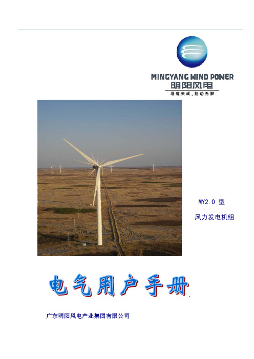
明阳2.0型风力发电机组用户手册(电气)
航对风。
风机机舱罩由玻璃钢制成,它可保护机舱内部各组件免受雨、雪、灰尘、太阳辐射等的破坏。从
塔架内通过爬梯可以到达机舱,爬梯上配备有助爬器(可选)。
机舱内部包含有一台维护吊机,额定起重重量为 250kg。
塔架外形为锥形,塔架采用特殊的防腐蚀保护工艺,保证风场当地环境生存期的防腐要求。
风力发电机组的所有功能由控制系统启动并管理,并具有先进的控制策略。
5.4 机组操作 .......................................................................... 29 5.4.1 就地操作 ...................................................................... 29 5.4.2 远程操作 ...................................................................... 35
变流器与电网连接。
风力发电机制动系统由两部分组成,其主制动器为空气动力学制动,通过 3 个叶片独立变桨实现。
35kV风电场集电线路施工说明书

图号某49.5MW风电场35kV集电线路施工图设计说明书批准:审核:校核:编写:说明书目录1.总论1.1 设计依据1.2 工程名称及编号1.3 设计范围1.4 设计所依据的主要规程、规范1.5 主要技术经济指标2.线路路径2.1风电场概况2.2 路径概况2.3 路径描述2.4 主要交叉跨越3.气象条件4.导线、地线和电缆4.1 导、地线型号4.2导、地线物理特性4.3导、地线最大使用应力及年平均运行应力4.4导、地线初伸长的处理4.5导、地线防振措施4.6导、地线的联接与架线4.7导线相序4.8电缆型号及所需特性5.绝缘设计和金具选择5.1绝缘设计5.2金具选择5.3金具组装串6.防雷设计6.1 防雷措施6.2 接地装置6.3接地电阻7.导线对地及交叉跨越距离7.1 对地距离7.2 交叉跨越距离7.3线路与弱电线路的交叉角7.4线路与树木的最小距离8.杆塔设计8.1 杆塔设计依据8.2 杆塔荷载8.3 杆塔选型8.4本工程选用塔型技术参数一览表9.基础设计9.1基础设计依据9.2本风电场地貌、地质情况9.4基础选型9.4基础材料10通信保护设计11 施工注意事项11.1验收标准11.2电气部分施工注意事项11.3结构部分施工注意事项11.4电缆部分施工注意事项12 本工程转角桩坐标13 附件-卷册目录1.总论1.1 设计依据1)某风电场新建工程可行性研究报告。
2)双方所签订的设计合同。
1.2 工程名称及编号工程名称:某49.5MW风电项目。
工程编号:1.3 设计范围1.3.1、从风机附近的电缆引上杆塔至220kV升压变电站的电缆出口经一段直埋电缆至终端下电缆杆塔的35kV集电线路架空部分本体设计。
1.3.2、随本线路架设的ADSS光缆的安装设计。
1.4 设计所依据的主要规程、规范1 《66kV及以下架空电力线路设计规范》GB 50061-972 《交流电气装置的过电压保护和绝缘配合》DL/T620-19973 《交流电气装置的接地》DL/T621-19974 《架空送电线路杆塔结构设计技术规定》DL/T5154-20025 《送电线路基础设计技术规定》SDGJ62-846 《建筑结构荷载规范》GB 50009-20017 《混凝土结构设计规范》GB 50010-20028 《建筑地基基础设计规范》GB 50007-20029 《钢结构设计规范》GB 50017-200310 《建筑抗震设计规范》GB 50011-200111 《电力设施抗震设计规范》GB 50260-961.5主要技术经济指标1.5.1 线路额定电压: 35kV。
风力发电机使用说明书

风力发电机使用说明书一概述:FD2.0-150W 、FD2.2-200W、FD2.6-300W、FD2.8-600W 、FD3.2-1000W 、FD4.0-2000W、FD5.0-3000W、FD6.0-5000W、FD8.0-10000W、FD12.0-20KW、FD12.5-30KW型风力发电机,是一种风能转变为机械能,再转变为电能的机电设备,利用风力发电,向蓄电池充电蓄存电能,还可以把蓄存的电能转变为220V/50Z 的交流电源,风力发电不需燃料,无污染、无噪音。
它普遍适用于风能条件好,远离电网,或电网不正常的地区,供给照明、电视机、探照灯、放像、通讯设备和电动工具用电。
二机组的主要技术参数:1 、机器型式:水平轴迎风向/垂直轴2 、叶片型式:螺旋桨型3 、叶片数目:3 片4 、风轮直径:2.6 米、2.8 米、3.8 米、5.0米、7.0米、8.0米5 、额定转速:400 转/ 分、200转/分、150转/分6 、额定功率:300W 、500W 、1KW、2KW、3KW、5KW、10KW、20KW、30KW7 、工作电压:24V 、48V 、96V 、108V、220V、380V8 、配蓄电池:24V 、48V 、96V、108V、216V、360V9 、起动风速:3米/ 秒10 、设计风速:8 米/ 秒11 、工作范围:3~ 20 米/ 秒12 、旋转方向:顺时针(面向风轮)13 、风能利用系数:0.414 、高速比:6 :1~8 :115 、调速方式:自动调偏风16 、立架高度:6~12米三结构组成:主要有:风轮、发电机、尾舵、支架、电气系统等组成。
(见图)1,叶片2,发电机3,回转体4,导流罩5,尾翼舵6,拉索7,蓄电池8,逆变电源9,用电器10,混凝土基座11,立杆四垂直轴机组1.机翼型垂直轴微风启动,机翼型叶片组合,低噪音,是理想的商品楼座及家用型产品垂直轴微风启动,机翼型叶片组合,低噪音,是理想的商品楼座和家用产品2.垂直轴C型垂直轴微风启动,先进的“C”形叶片,充分发挥“风动力学原理”灵活的“风洞”装置,使风能转换率达到了最大利用五机组安装:1 、地点选择:风机应安装在使风能充分利用的地方,且无高大障碍物,使风机四面临风,或者立于小山包之上,或虽处凹地,但形如走廊,总有疾风劲吹而得天独厚。
风电瓦斯闭锁说明书

风电瓦斯闭锁说明书风电瓦斯闭锁说明书风电瓦斯闭锁说明书风电瓦斯闭锁说明书1. 系统功能1)掘进工作面甲烷浓度达到或超过1.0%CH4时,声光报警;掘进工作面甲烷浓度达到或超过1.5%CH4时,切断掘进巷道内全部非本质安全型电气设备的电源并闭锁;当掘进工作面甲烷浓度低于1.0%CH4时,自动解锁;2)当掘进工作面回风流中的甲烷浓度达到或超过1.0%CH4时,声光报警,同时切断掘进巷道内全部非本质安全型电气设备的电源并闭锁;当掘进工作面回风流中的甲烷浓度低于1.0%CH4时,自动解锁;3)被串掘进工作面入风流中甲烷浓度达到或超过0.5%CH4时,声光报警,同时切断被串掘进巷道内全部非本质安全型电气设备的电源并闭锁;当被串掘进工作面入风流中甲烷浓度低于0.5%CH4时,自动解锁;4)局部通风机停止运转或风筒风量低于规定值时,声光报警,同时切断供风区域的全部非本质安全型电气设备的电源并闭锁;当局部通风机或风筒恢复正常工作时,自动解锁;5)局部通风机停止运转,掘进工作面或回风流中甲烷浓度大于3.0%CH4时,应对局部通风机进行闭锁使之不能起动,只有通过密码操作软件或使用专用工具方可人工解锁;当掘进工作面或回风流中甲烷浓度低于1.5%CH4时,自动解锁。
6)与闭锁控制有关的设备(含分站、电源、甲烷传感器、断电控制器等)故障或断电时,切断该设备所监控区域的全部非本质安全型电气设备的电源并闭锁。
与闭锁控制有关的设备接通电源1min内,应继续闭锁该设备所监控区域的全部非本质安全型电气设备的电源。
当与闭锁控制有关的设备工作正常并稳定运行后,自动解锁。
严禁对局部通风机进行故障闭锁控制。
2.调试步骤(无上位机的情况下)风电瓦斯闭锁试验方法甲烷、风、电闭锁试验按下列方法进行测试:甲烷、风、电闭锁试验按下列方法进行测试(2路近程和6路远程在常闭情况下测量):(1) 1号输入口:接高低浓度甲烷传感器T1,监测掘进工作面瓦斯; (2) 2号输入口:接高低浓度甲烷传感器T2,监测掘进工作回风流中瓦斯,(3) 3号输入口:接高低浓度甲烷传感器T3,监测被串掘进工作面入风流中瓦斯,(4) 4号输入口:接设备开停传感器KT1,监测局部通风机开停; (5) 5号输入口:接设备开停传感器KT2,监测局部通风机开停; (6) 6 号输入口:接风筒风量开关传感器KT3,监测风筒风量; (7) 1号控制口:KZ1接断电器DDQ1,控制掘进巷道内全部非本质安全型电气设备的电源;(8) 2号控制口:KZ2接断电器DDQ2,控制被串掘进巷道内全部非本质安全型电气设备的电源;(9) 3号控制口:KZ3接断电器DDQ3,控制供风区域的全部非本质安全型电气设备的电源;(10) 4号控制口:KZ4接断电器DDQ4,控制局部通风机; (11) 5号控制口:KZ5接声光报警器,控制声光报警。
风力发电设备使用说明书
风力发电设备使用说明书使用说明书一、产品概述风力发电设备是一种利用风能将其转化为电能的设备,广泛应用于各类发电场所。
本使用说明书旨在向用户提供详细的使用指南,确保用户正确、安全地操作风力发电设备。
二、安装与组装1.选择安装位置:选择一个无障碍、充分暴露在风中的位置进行安装,远离高楼大厦、树木、电线等障碍物。
2.组装:将各个组件正确连接,确保连接紧固、电线接触良好。
三、开机前准备1.检查设备:确保设备连接牢固,无松动或磨损现象。
2.检查电缆:检查电缆的绝缘情况,如果发现损坏应及时更换。
四、开机操作1.打开主电源开关:将主电源开关置于"ON"位置。
2.启动风力发电设备:按下启动按钮,设备开始运转。
3.监测发电指示:观察设备上的发电指示灯,确保设备正常运行。
五、停机操作1.关闭风力发电设备:按下停机按钮,设备停止运转。
2.关闭主电源开关:将主电源开关置于"OFF"位置。
六、设备维护1.定期检查:每隔一段时间对设备进行检查,确保各部件无松动、损坏现象。
2.清洁设备:定期清洁设备表面,清除灰尘和污垢。
3.及时维修:如果发现设备存在故障或异常情况,应及时联系售后服务中心或专业维修人员处理。
七、安全注意事项1.禁止靠近旋转部分:设备运转时,绝对禁止靠近旋转部分,以免造成人员伤害。
2.禁止操作不当:请仅由经过专业培训的人员操作风力发电设备,以免发生意外事故。
3.避免恶劣天气:如果遭遇强风、雷雨、冰雹等恶劣天气,请及时停机并采取应对措施。
八、故障排除在使用过程中,如果遇到设备故障,请参考以下故障排除指南:1.无法启动:检查电源是否正常连接,电线是否健康。
2.设备发热:检查散热系统是否正常运行,是否存在堵塞情况。
3.异常噪音:检查设备连接是否牢固,是否有松动部件。
如果以上故障排除指南仍无法解决问题,请联系专业维修人员。
九、环境保护在使用和维护设备时,请注意环境保护:1.合理用电:请勿浪费电能,节约用电。
华锐风电 SL3000 系列风力发电机组电控系统说明书

SL3000系列风力发电机组电控系统说明书华锐风电科技(集团)股份有限公司2010年3月目录前言 (3)第一章 SL3000 风机电控系统简介 (8)1.1 SL3000风力发电机组电控系统的组成 (8)1.2 SL3000风力发电机组电控系统的主要特点 (8)第二章 SL3000 风机电源系统 (9)2.1 箱式变压器参数 (9)2.2 辅助变压器的参数 (9)2.3 箱式变电站的系统图 (10)第三章 SL3000 变速恒频控制系统 (11)3.1 双馈异步发电机 (11)3.1.1 介绍 (11)3.1.2 技术条件 (11)3.2 变频器 (12)3.2.1 整套的变频器系统包括下列部件 (12)3.2.2 特征电气参数 (13)3.2.3 变频器系统的连接 (13)3.3 传感器 (15)3.4 其他功能 (15)第四章 SL3000 偏航控制系统 (17)4.1 介绍 (17)4.1.1 偏航驱动系统 (17)4.1.2 制动器 (17)4.1.3 限位保护 (17)4.2 电机参数 (17)4.3 制动器参数 (18)4.4 偏航变频器 (18)第五章 SL3000 变桨控制系统 (19)5.1 变桨系统介绍 (19)5.2 变桨齿轮箱 (19)5.3 变桨电气系统 (20)5.3.1 变桨电动机 (20)5.3.2 变桨变频器 (20)5.3.3 电池系统 (20)5.3.4 传感器 (20)5.4 雷电保护 (21)5.5 控制接口 (21)5.5.1 软件接口 (21)5.5.2 硬连线信号 (21)5.5.3 软件 (22)第六章 SL3000 PLC控制系统 (23)6.1 PLC控制系统描述 (23)6.2 PLC程序结构 (23)第七章 SL3000 风机的保护 (24)7.1 防雷保护系统 (24)7.2 接地系统保护 (24)7.3 电路及控制保护系统 (25)第八章 SL3000风机主要配件 (26)8.1 轮毂滑环简介 (26)8.1.2 电气性能 (26)8.1.3 加热 (26)8.2 OP2操作屏 (27)8.2.1 说明 (27)8.2.2 正视图 (27)8.2.3 按钮描述 (27)附件1 主要控制柜的主要内容及功能介绍 (29)附件2 电气图纸 (30)前言SL3000风力发电机组采用变桨矩、变速恒频等技术,是当今世界风力发电最先进的技术代表,具有发电量大、发电品质高、结构紧凑等优点。
风力发电使用手册通用版中文

航天科工哈尔滨风华有限公司电站设备分公司风力发电机组安装及使用说明航天科工哈尔滨风华有限公司电站设备分公司敬告:●所有规格如有变更,恕不另行通知。
●安装风力发电机组必须符合该地区法律法规,或征得所在地政府同意。
●安装、维修以及拆除风力发电机组务必选择无风天气进行。
●风力发电机组包括机械及电子设备,务必由专业人员施工并注意安全。
●图片颜色或外形可能与实物不符。
●切勿使风力发电机组运行在空载(没有连接任何负载)状态下。
●如有任何问题请联系经销商或代理商●本说明书中涉及到的安全标示如下危险:不当操作将有可能导致严重人身伤害。
注意:不当操作将有可能导致产品损坏或人身伤害。
航天科工哈尔滨风华有限公司电站设备分公司目录0 安全注意事项 (4)1 适用型号和部件说明 (5)2 包装箱内容 (6)2.1 包装箱内容 (6)2.2 运输方式 (6)2.3 装载点 (6)3 安装风力发电机组 (8)3.1 选择安装场地 (8)3.2 浇筑地基和组装风力发电机塔架 (8)3.3 安装风力发电机到独立塔架上 (8)3.4 安装风力发电机到液压塔架上 (11)4 控制器接线 (13)4.1 连接示意图 (13)4.2 控制器参数 (14)4.3 控制器安装 (14)4.4接线 (15)4.5 网络部分 (16)4.5.1 GPRS模块 (16)4.5.2 局域网模块 (19)5 蓄电池配置 (20)6 维护方法 (21)6.1 维护计划 (21)6.2 备件清单 (21)7 断开或拆卸风力发电机 (23)7.1 独立塔架 (23)7.2 液压塔架 (23)8 其他 (24)航天科工哈尔滨风华有限公司电站设备分公司0 安全注意事项风机处于放倒状态时不得尝试偏航。
控制器处于手动运行状态时,操作人员不得离开风机现场。
航天科工哈尔滨风华有限公司电站设备分公司1 适用型号和部件说明本手册适用于以下型号的风力发电机。
型号FD6.4-5000 FD8.0-10000 FD12.0-20000 FD12.0-30000额定功率(W) 5000 10000 20000 30000额定电压 (V) 240 240 240 240风叶直径(M) 6.4 8.0 10.0 12.0启动风速(m/s) 2.5 2.5 2.5 2.5额定风速(m/s)10 10 12 12.5安全风速(m/s) 45 45 45 45额定转速(r/m)180 180 90 75叶片材料GFRP GFRP GFRP GFRP叶片数量 3 3 3 3噪音( dBa) ≤70 ≤70 ≤70 ≤70风力发电机主要构成部件序号名称序号名称1 风叶法兰盘8 风速风向仪2 底板9 控制器3 阀块10 液压刹车4 储能罐11 刹车盘5 偏航电机12 发电机6 液压站电机和油箱13 回转支撑7 卸荷器14 偏航刹车航天科工哈尔滨风华有限公司电站设备分公司2 包装箱内容2.1 包装箱内容序号名称件数包装形式1 发电机(含电缆、风叶法兰) 1 胶合板2 地面控制器 1 胶合板3 风叶 1 胶合板4 风帽和附件 1 胶合板塔架包装参考塔架说明书。
风力发电机使用说明书
风力发电机使用说明书尊敬的用户:感谢您购买我们的风力发电机。
为了确保您正确、顺利地使用该设备,我们特别为您提供以下使用说明,请您仔细阅读并按照说明进行操作。
一、产品概述风力发电机是一种利用风能将其转换为电能的设备。
它由风轮、发电机、转子轴、转子叶片和控制系统等部件组成。
通过合理布置设备,利用风能驱动转子叶片旋转,进而带动发电机转动,最终将机械能转化为电能。
二、安全使用须知1. 在使用风力发电机之前,请确保已详细阅读并理解本使用说明书。
如有任何不明白之处,请咨询售后服务。
2. 在操作风力发电机时,请保持仪表盘及其周围的清洁,防止灰尘、油污等杂质对设备产生不利影响。
3. 在连接发电机电源之前,务必切断外部电源,并确保风速不低于3级。
4. 为了保证人身安全,请穿戴工作服、安全帽等相关防护用具,并严禁擅自改动设备结构或私自拆卸零部件。
5. 在设备运行期间,不得将手或其他物体伸入风轮转动范围内,以免造成伤害。
三、设备安装与调试1. 在安装风力发电机时,需选择开阔、无遮挡的场地,并确保其离建筑物、电线杆等障碍物的距离符合国家标准。
2. 确保风轮叶片安装正确,叶片之间保持一定间隙,以免叶片受到相互碰撞而受损。
3. 连接电源之前,请先检查所有接线是否牢固可靠,并严禁接反或短路,以免导致设备故障或事故发生。
4. 在全部安装完成后,可进行风力发电机的初次调试。
开启设备,通过监测设备的运行状态,检查各项指标是否符合要求。
如发现异常情况,请立即关闭设备,并联系售后服务。
四、设备维护与保养1. 定期检查发电机的外观及连接螺丝是否松动,如有发现问题请及时修复。
2. 清洁叶片和机壳等部件,防止积尘和杂物影响设备运行效果。
3. 检查设备的电缆和电源是否正常,以确保电源连接畅通无误。
4. 如发现机械部分或电气元件出现故障或损坏,应立即停止使用,并联系厂家或售后服务进行维修。
五、故障排除1. 故障现象:发电机无法启动。
可能原因:电源故障、电气元件接触不良。
风力发电机说明书
风力发电机说明书风力发电机说明书1.产品介绍1.1 产品概述本文档旨在提供关于风力发电机的详细技术说明和使用指南。
风力发电机是一种利用风能转化为电能的装置,利用风轮的旋转驱动发电机产生电能。
本产品采用最先进的风能转化技术,具有高效能、环保节能、可靠性高等优点。
1.2 产品特点●高效能:本产品采用先进的风轮设计和优化的发电机结构,提高了发电机的效率和输出功率。
●环保节能:风力发电是一种绿色能源,不产生二氧化碳等环境污染物,对环境友好。
●可靠性高:本产品采用优质材料和稳定性强的组件,具有较高的可靠性和耐用度。
2.安装要求2.1 安装位置要求风力发电机需要安装在开阔无遮挡的地方,远离高建筑物、树木、或其他阻挡风力的障碍物。
优选安装在海拔较高、风力较大的地区,以提高发电效率。
2.2 安装基础要求安装基础需要具备一定的强度和稳定性,可以承受风力发电机的重量和风力引起的振动。
建议使用混凝土基础或钢结构基础进行安装。
2.3 安装步骤●选择合适的安装位置,确保没有障碍物遮挡风力。
●按照安装基础要求,进行基础的施工工作。
●将风力发电机的主体部件安装在基础上,并根据说明书进行组装。
●连接风力发电机与电网,确保接线正确,并进行必要的安全检查。
●检查安装是否稳固,确保风力发电机可以正常运行。
3.使用方法3.1 启停机操作●启动:将风力发电机连接电网后,按下启动按钮,机器即可自动运行并开始发电。
●停止:按下停止按钮,风力发电机将停止运行并断开与电网的连接。
3.2 监控和维护●定期检查机器运行状态,确保发电机正常工作。
●定期清洁发电机表面和风轮,清除积灰和杂物。
●如有异常情况或故障发生,及时联系专业人员进行维修。
4.安全注意事项4.1 高压安全风力发电机涉及高压电流,操作人员在维修和保养过程中必须戴好防护设备,确保人身安全。
4.2 防雷防护风力发电机安装过程中,需安装防雷装置,防止雷击损坏发电机及相关设备。
4.3 防风安全在风力较大的情况下,风力发电机可能产生较大的振动和噪声,使用人员需保持安全距离,避免受伤。
美菱电风扇MFT66-A说明书

电风扇说明书
1.开机、风量设定:
接通电源,按“风量/开”按钮,电风扇开始工作,为“弱”风档。
通过按“风量/开”按钮,可控制风量的强弱,每按一次,风量会在“弱”、“中”、“强”档之间切换一次,同时相应的风量指示灯亮。
2.风类选择:
通过按“风类”按钮可选择不同的风类方式(正常风、自然风、和睡眠风)。
每按一次“风类”按钮,风的类型变化一次,同时相应的指示灯亮,两灯都不亮,表示正常风。
睡眠风“强”睡眠风:风扇先吹半小时强自然风,然后半小时中等自然风,最后是吹弱自然风直到设定时间结束。
“中”睡眠风:风扇先吹一小时中等自然凤,然后是吹弱自然风直到设定时间结束。
“弱”睡眠风:同“弱”自然风。
②自然风电风扇模仿自然变化的风。
③正常风电风扇风力大小不变。
3.定时设定:
通过按“定时”按钮可设定电风扇工作时间,每按一次“定时”按钮,会累加1小时(1至7小时范围内),相应的指示灯亮。
4.摇头设定:
通过按“摇头”按钮可设定电风扇是否摇头。
5.负离子净化:通过按“负离子”按钮可设定电风扇是否发生负离子,进行空气净化,同时相应的指示灯亮。
风力发电机使用手册(翻译)

风⼒发电机使⽤⼿册(翻译)⽬录Cataloge第⼀部分The first part (1)⼀、概述:outline (2)⼆、机组技术参数:the unit technical parameter (2)三、结构组成:the structure composes (3)四、开箱检查:open the case and check out (4)五、选择安装地点choose installation site (5)六、地基施⼯指导the ground construction instruct (5)七、机组安装:install the unit (6)⼋、注意事项: attention matters (8)九、⽇常维护routine maintenance (9)⼗、故障排除trouble shooting (9)⼗⼀、产品保修Warranty (10)第⼆部分 The Second part 使⽤说明书Operating instruction manual (11)第⼀部分The first part感谢您购买“⽇普昇”牌RPS系列⼩型风⼒发电机,安装使⽤前,请仔细阅读本⽤户使⽤⼿册,有助于保证产品的安全、正常运⾏并充分发挥其优越性能。
愿您尽情享受RPS系列风⼒发电机带给您的光明与快乐!本⼿册内所指风机即为RPS系列⼩型风⼒发电机。
Thank you for buying the RPS series of small wind power generations , before you using it, please read the users manual serious, it is helpful in the guarantee productsecurity、the normal operation and displays its high performance fully. Hope you can enjoy the bright and happy taking by the RPS series wind power generations.⼀、概述:outline风⼒发电机,是⼀种将风能转变为机械能,再转变为电能的机电设备,利⽤风⼒发电,向蓄电池充电蓄存电能,还可以把蓄存的电能转变为220V(380V)/50HZ 的交流电源,风⼒发电不需燃料,⽆污染、⽆噪⾳。
- 1、下载文档前请自行甄别文档内容的完整性,平台不提供额外的编辑、内容补充、找答案等附加服务。
- 2、"仅部分预览"的文档,不可在线预览部分如存在完整性等问题,可反馈申请退款(可完整预览的文档不适用该条件!)。
- 3、如文档侵犯您的权益,请联系客服反馈,我们会尽快为您处理(人工客服工作时间:9:00-18:30)。
1.引言根据任务书的设计要求以及结和工程的实际情况,此次设计为4X49.5MW风电场电气部分设计。
工程分为四期,单期工程为49.5MW,本次设计以一期工程为例。
本期工程选用 1.5MW风力发电机,共用33台。
每台风力发电机采用1600kVA的升压变压器,将出口电压690V升至35KV并送入35KV集电线路中。
通过架空线路将电送入风电场110KV升压变电站中。
本次设计是在康文彪老师的精心指导下制作完成的。
康老师知识渊博、严谨认真,善于调动学生的积极性,喜欢捕捉新鲜事物以及研究方向。
在设计思路上给了我很大的帮助和指引。
此次设计让我懂得了风力发电厂电气部分设计的基本方法和思路。
培养了我查找资料、计算、绘图、分析等能力。
在老师的指引下独立完成任务。
在此,我对老师表达由衷的感谢和深深的敬意。
2■风力发电厂电气设计的主要内容2.1内容背景在社会和经济的不断发展和建设中,能源的消耗也在不断的加重。
煤,石油,天然气是人类赖以生存的主要能源。
这些能源都是不可再生资源。
为了解决这类能源问题必须积极发展新能源,坚持可持续发展。
风力资源具有良好的开发前景,利用风力发电等开发风力资源能很好的解决一系列能源问题,对保护环境具有重要意乂。
风力发电是目前为止全世界增长最快的能源开发,风力发电的装机容量每年保持超过20%的增长速度。
截止2020年底,全球的风电的装机容量能够达到1200GW,足以保证约5000万的普通家庭或者是9500万的居民的用电需求。
德国,丹麦以及西班牙是世界上风力资源开发和发展最好的3个国家。
德国风力发电已经占该国总发电量的3%,丹麦的风力发电超过总发电量的12 %。
现在全世界大约已经有55多个国家加入了风力发电的队伍,大约参与风电行业的就业员工已有20万人。
我国的风力资源富饶,大概可开发的风力资源有20亿千瓦时,内陆及近海的风力资源开发超过有15亿千瓦时。
海上可以开发利用的风能资源约有7.5亿千瓦时。
到2010年为止我国每年用电总量大约是41923亿千瓦时左右,但我国经济能够开发利用的风力发电资源仅在10千瓦时上下。
到2010年底,我国并网的风力发电装机容量已经达到2596兆瓦。
风力发电的开发和利用,在目前看来前景是光明无限的。
2.2风力发电机的选择与布置本次设计的风力发电机初步选用单机容量为WTG1500A的双馈异步发电机,共布置33台。
参数如下:由于风力发电机输出电压为690V,所以每台风力发电机配置一台箱式变压器, 选用一机一变的接线形式,箱变内装设1600k V A升压变压器。
参数如下:箱变的出口电压为35kV,本期33台风力发电机分成4组,经4回集电线路(35kV电缆线路)接入风电场110kV变电站35kV母线。
2.3引线的选择由于考虑到风力发电场施工方面因素的影响,所以在一条线路上的8台风力发电机,前面的4台风力发电机使用50m卅截面积的电缆线路,后面的4台风力发电机选用150m 卅截面积的电缆线路。
在风力发电场中的风力发电机到风电场中心的升压变电站之间的集电线路准备选用35KV架空线。
采用架空线,其对地电容比较小。
当发生单相接地等故障时,一般是以瞬时故障为主的,可以选用中心点不接地或者是经消弧线圈接地的方式,来避免风电机组无为跳闸的情况。
选用的型号为:LGJ-150/25型的铝锰合金镀层钢芯铝绞线的架空线路。
数量为60km。
地线选用GJ-35型的钢芯铝绞线路来用。
3. 风电场变压器的选择3.1风力发电机组的升压变压器的选择风力发电机输出电压为690V。
按照一机一变的接线形式,所以根据风电场电气系统典型设计手册,风力发电机出口电压变压器初步选为1600kVA的升压变3.2风电场主变压器的选择风电场主变压器的容量选择,应按照在正常运行的情况下有最大功率通过时而且不过载的方式来确定容量的选择,避免了出现功率的“瓶颈”的现象。
如果选择过大的容量会加大投资,并且会增加有功功率和无功功率的损耗。
由于风电场的实际情况,考虑到负荷率较小和风电机组的功率因数在1左右, 根据风电场电气系统典型设计手册,能够选用等于风力发电场发电容量的主变压器。
在实际选择变压器的容量上,应根据上述原则选取近似并且稍大于风力发电场发电容量的标准。
本次设计的单期工程发电量为49.5MW,则可以选择一台容量为50MVA的三相油浸式双绕组有载调压变压器作为该期工程的主变压器。
3.3厂用变压器的选择厂用电的设计应该按照运行、检修以及施工的要求,以及从全厂发展规划考虑, 妥善地解决因分期建设而引起的问题,并且积极慎重的采用经过鉴定的新技术和新设备来使设计满足经济合理、技术先进。
保证机组安全以及经济和满发地运行。
厂用变压器的容量选择应按照高压厂用电计算负荷和低压厂用电计算负荷之间进行选择,而厂用工作变压器的型式选择由《电力工程电气设备手册》查得;高压厂用变压器的容量:49.51% = 505.1表3-3高压厂用变压器采用S7—630/354. 风电场电气主接线的设计4.1电气主接线的设计原则:(1)可靠性,供电可靠性是电力生产的基本要求。
(2)灵活性,发电厂主接线应该满足在调度、检修以及扩建的灵活性。
(3)经济性,在满足可靠性和灵活性的前提下,还应尽量做到经济合理。
4.2常见的电气主接线分类:主接线形式可以分为两大类:有汇流母线和无汇流母线。
有汇流母线:简称母线,是汇集和分配电能的设备。
无汇流母线:使用开关电器较少,占地面积较小,一般只适用于进出线回路少、不再扩建和发展的发电厂或变电站。
4.3风电场电气主接线的形式:从设计要求所给的电压等级、出线回路数以及电气主接线的可靠性和灵活性、经济性等方面因素考虑,35KV应采用单母线分段形式,通过3回35KV线路汇集后送至100KV母线。
110KV采用单母线接线形式。
风电机组采用单元接线。
单元接线:单元接线是最简单的接线形式,即发电机和主变压器组成一个单元,发电机生产的电能直接输送给变压器,经过变压器升压后送给系统。
单母线接线:单母线接线是以一条母线用为配电装置中的电能汇集节点, 是有 母线接线形式中最简单的接线形式。
单母线接线的优点是:接线简单清淅、设备少、操作简单、便于扩建和采用成 套配电装置。
单母线接线的缺点:可靠性较低,当其中的任一断路器检修停运,其所在回路 必须停电,而当母线或母线隔壁离开关故障或检修的时候, 由于母线停运,整个 配电装置都需要停电,也就有可能造成整个厂站的停电。
单母线分段接线:在配电装置中有多个电源存在的时候,单母线不在适用,此 时可以将单母线根据电源的数目进行分段,这就是单母线分段接线形式。
单母线分段接线具有以下优点: 1) 重要用户可以从两段母线上引出两个回路,由不同的电源供电。
2) 当一段母线发生故障或需要要检修的时候,分段断路器可以断开,保证另一 段母线的正常运行。
5. 短路计算5.1短路计算的目的(1) 电气主接线比选 (2) 选择导体和电器 (3) 确定中性点接地方式 (4) 计算软导线的短路摇摆 (5) 确定分裂导线间隔棒的间距(6) 验算接地装置的接触电压和跨步电压 (7) 选择继电保护装置和进行整定计算 5.2各点短路电流计算取基准容量S B =100MVA ,基准电压U B 用各级的平均电压 各元件电抗的标幺值如下:单台风机:X=x d -SB =0.1411 X 100=9.22S N P /COS 单台箱变%墻&誥詈=3.75线路阻抗:XL —U Bv =0.4x 10 X300 =0.292%为单位长度的电抗0.4主变压器: X _ U K % S B _ 10.5% , 100X B 2* = • ==U.2I系统架空线路阻抗: X L 2*=X1• u av =0.4x 50 x1152=0.15d 点短路计算(110KV 母线)根据《电力系统分析》第十章电力系统三相短路电流的实用计算,如果不能确定 同步发电机短路前的运行参数,近似取 E 0〜1.05X 总+X 升压变总=0.393+0.21=0.603、, (0.292 + 0.15) '0.603 门 …X 合==0.256(0.292 + 0.15) + 0.603则计算电抗:X js1=X ?* 鱼= 0.256 ' 495^=0.129 S B100查短路电流运算曲线表找出0s , 2s , 4s 短路电流周期分量标幺值。
1*0 =8.4 I *2 =2.75 I *4 =2.5则短路电流:I d = I * -S G?.3U BI 0=2.1KA I2=0.69KA I 4=0.625KA冲击电流: I ch = 1.82Io =5.355KA d 2点短路计算(35KV 母线) X系统阻抗+X升压变总=0.292+0.21=0.502则计算电抗: X js2=X ?* •邑=0.253S B查短路电流运算曲线表找出0s , 2s , 4s 短路电流周期分量标幺值。
I *0 =4.21 I *2 =2.47 1*4 =2.4I 0=3.32KA 12=1.947KA 14=1.89KAX 总=(X 风机+X 出口变)总=9.22 +3.75 33 =0.393 则短路电流:I d I *S G ?• 3U B冲击电流:I ch = 1.8/2l'o =8.211KAd 3点短路计算(发电机出口侧)+—出口变总风机=3.75 X 0.502 X 2.37=4.46X js3 = X ?*•邑=2.25S B查短路电流运算曲线表找出0s , 2s , 4s 短路电流周期分量标幺值。
I *0 = 1*2 = I *4 =0.4710= 12= 14=18.99KA冲击电流:l ch = 1.&"2 Io=48.41KA6. 电气设备的配置6.1电器选择的一般要求正确的选择电器是使电气主接线和配电装置达到安全、经济运行的重要条件。
在进行电器选择时,应根据工程实际情况,在保证安全、可靠的前提下,积极而 稳妥的采用新技术,并注意节省投资,选择合适的电器。
6.2断路器与隔离开关的选择由于断路器在电器接线中装设的部位不同,对其性能要求不同,在选择断路器时,应结合装设的特点及产品的技术经济指标综合考虑。
6.2.1断路器的选择要满足以下的特殊要求:① 合闸时触头不应有明显弹跳、熔焊;② 分闸时不应重击穿,或重击穿概率很低; ③ 应有承受合闸涌流的能力;④ 经常投切的断路器应具有频繁操作的能力; ⑤ 断路器的额定电流,不应小于装置长期允许的电流的1.35倍;6.2.2 110KV 母线短路由短路电流计算结果可知:I 0=2.1KA 12 =0.69KA l ;=0.625KA2.37X B =X Z X出口变总则短路电流:I d I *S G ? ■ 3U冲击电流:I ch = 1.8/2l ‘0 =5.355KA 最大持续工作电流:周期分量热效应(3s 时):,2 , 2 , 2Q P = (I)+10'(l 2)+^4)'T122 2 22.1 +0.69 +0.625 ,Q P =' 3=1.3212根据110K V 户外配电装置在本设计的具体要求,靠近母线的隔离开关宜选用垂伸 缩。