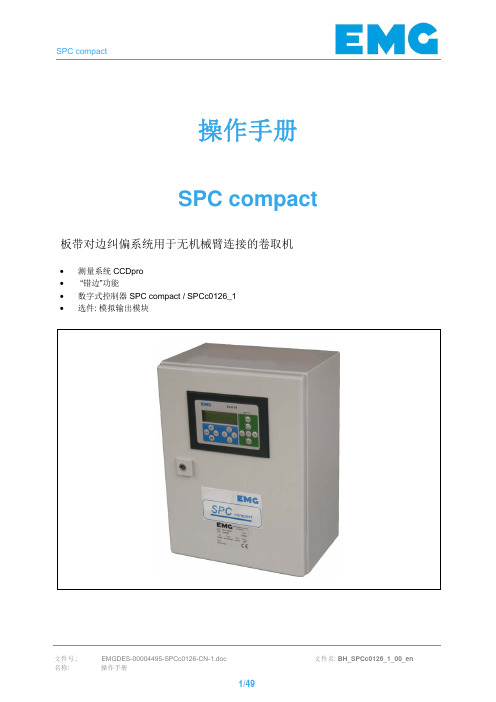
EMG纠偏系统说明书
EMG EPC调试手册

文件名: BH_SPCc0126_1_00_en
1/49
SPC compact
修改情况: 00 新版格式 + 安全措施
名字: Roet
日期: 16.09.08
© 2012 EMG Automation GmbH. 版权所有 本文档拷贝权归属 EMG Automation GmbH. 本文所涉及的技术信息禁止以任何形式拷 贝、传播或未经授权对外交流或用于竞争目的。
6/49
SPC compact
1.3
安全规程的违背
EMG Automation GmbH 对于违背本手册所描述的安全规程而造成的任何损失均不负责 任。 尤其适用于如下情况所造成的损失: • 使用不当或操作有误。 • 不遵守本手册中的安全要求。 • 维护或修理工作不按要求执行。 • 工作组件或工具选择有误。
安全
简介 总则 安全规程的违背 基本安全预防措施 地方性法规,官方指令和规程 应用范围 构造及目的 参照符号表 安全规程总述 技术状况介绍 安全防护装置的移除 具体安全规程 机械危险 电气危险 液压危险 责任和资质要求 授权人员/雇员资质 设备故障和损坏的告知责任 必要的防护服 禁止改造和 变更 维护责任
危险
电击致死 被高压电击 只允许受训人员在使用 ESD-防护措施的情况下接触电路部分。
1.7.3
液压危险
小心
轻度人身伤害 被油液喷射 在维护或者维修工作开始时必须确认液压系统已泄压。 • • • • 不要改变说明书和维护计划中所指定的泵的压力 密封的或者用其他方式封死的调节阀不要触动。 当对液压系统进行作业时(如:更换液压软管 ) ,需准备容器或者收集盘来收集滴下或 渗漏的油液。 被替换下来的液压油要注入适当的回收容器并依照环保条例进行处置。
E+L EPC纠偏系统说明书

E+L-EPC纠偏系统说明书本说明适用于德国E+L纠偏常规产品目录E+L-EPC纠偏系统说明书 (1)一、E+L-EPC纠偏系统总体说明 (3)二、E+L-EPC纠偏系统所需零件说明 (4)三、E+L-EPC纠偏系统机械安装说明 (5)3.1、控制器的安装 (5)3.2、电眼的安装 (5)3.2.1、通过EPC纠偏应用场合确认电眼安装位置 (5)3.2.2电眼的安装要求 (6)3.3、电机的安装 (6)3.3.1、确定电机型号 (6)3.3.2、确定电机机械中心 (7)3.3.3、调整电机机械中心 (7)3.3.4、安装电机 (7)3.4接近开关的安装 (7)3.4.1、接近开关感应片 (7)3.4.2、接近开关安装位置 (7)四、E+L-EPC纠偏系统配线说明 (10)4.1确认电压 (10)4.2、电机线布线要求 (10)4.3、E+L布线要求 (10)五、E+L-EPC纠偏面板说明 (10)六、E+L-EPC纠偏系统参数设定 (11)6.1、CAN网络群组地址设定 (11)6.1.1、RK4004地址设定 (11)6.1.2、FR5001电眼地址设定 (12)6.2、RK4004参数设定 (13)七、E+L-EPC纠偏系统试车 (15)八、E+L-EPC纠偏系统维护及故障说明 (15)8.1、EPC纠偏系统日常维护 (15)8.2、通过RK4004错误码信息来解决故障 (15)8.3、通过FR5001电眼错误码信息来解决故障 (16)九、附件 (17)附件一、电机尺寸图附件二、电机参数值附件三、EPC标准接线图纸附件四、RK4004控制板参数设定手册一、E+L-EPC纠偏系统总体说明我们将用一个电眼检测材料边缘来纠偏的纠偏系统称为EPC(Edge psoition control),以下简称EPC。
我们将用两个电眼检测材料中心来纠偏的纠偏系统成为CPC(Center position control),以下简称CPC。
EMG纠偏系统(设备)培训课件

EVB03 输出信号:±300ma、 ±1000ma
DAU16 输出信号:±300ma ±10V±22V 4路输出
模拟量输入模块
ቤተ መጻሕፍቲ ባይዱ
ADU02.1 8路输入,电压和电流信号
ADU02.2(精简版) 4路输入,电压和电流信号
开关量、模拟量输入输出模块
DEA01 8路开关量输入、8路输出
ADP01.1 X1:4路开关量输入+3路继电器输出 X2:4路模拟量输入+1路±10V输出
二、纠偏厂家
1、国外厂家 美国北美公司 美国FIFE公司 日本NIRECO公司 德国EMG公司 以上公司的产品几乎涵盖了电感式、光电式、电容式和CCD 摄像式传感器。从业绩上看,德国EMG占有的市场比例是很大 的,而且产品质量也是用户反映较好的。 2、国内厂家 西安恒利:电感式和光电式 上海科先:光电式、电感式(未上市)
式中,K2为常数;B为磁感应强度:h为带钢的厚度 ;b为带钢的宽度。
所以对于某一规格的带钢,在接收线圈内产生的感应电 动势ε1.
所以接收线圈的感应电动势与带钢在线圈内的宽度变化量成 反比。当被控带钢处于中间位置时,两边接收线圈输出相同。 当被控带钢向左跑偏时,左侧接收线圈的输出信号减小,右侧 接收线圈的输出信号增加。 在电感式对中检测系统中,两个接收线圈的输出信号的幅度 小,只有毫伏级,因此必须放大。根掘测量信号的特点,为了 提高测量精度,满足传感器输出的微小信号在各种状态下的放 大调节,同时能够有效地抑制干扰信号,可靠的检测出所需信 号,采用差动放大、整流和合适的滤波器等措施。
在带钢的下方安装光源上方安装ccd摄像头利用光源与带钢有明显的光学反差根据光学成像的原理通过测量镜头的带钢按一定比例成像到ccd上部分地遮住了光敏单元而成直线排列的光敏单元则将被测带钢的光学影像沿阵列方向的分布转换为时序的电平信号所得到的信号经前置放大峰值检出和二值化处理后用标准时钟脉冲填充计数再经计算即可得到带钢位置
EMG卷取机对边操作手册

操作手册程序: ST8121开卷机板带边部纠偏系统使用位置测量传感器EVK2-CP无机械连接∙数字控制器SPC 16∙光源发射器LIC修订情况: 名字: 日期:00 新版格式 + 安全措施Roet 2007-06-1501 目录调整(机械装置/组成部分) Roet 2008-02-0802 模拟量输入 DW 1 修正Qst 2009-01-16© 2011 EMG Automation GmbH. 版权所有本文档拷贝权归属EMG Automation GmbH. 本文所涉及的技术信息禁止以任何形式拷贝、传播或未经授权对外交流或用于竞争目的。
技术修订目录目录1安全错误!未定义书签。
1.1简介错误!未定义书签。
1.2总则错误!未定义书签。
1.3安全规程的违背错误!未定义书签。
1.4基本安全预防措施错误!未定义书签。
1.4.1地方性法规,官方指令和规程错误!未定义书签。
1.4.2应用范围错误!未定义书签。
1.5构造及目的错误!未定义书签。
1.5.1参照符号表错误!未定义书签。
1.6安全规程总述错误!未定义书签。
1.6.1技术状况介绍错误!未定义书签。
1.6.2安全防护装置的移除错误!未定义书签。
1.7具体安全规程错误!未定义书签。
1.7.1机械危险错误!未定义书签。
1.7.2电气危险错误!未定义书签。
1.7.3液压危险错误!未定义书签。
1.8责任和资质要求错误!未定义书签。
1.8.1授权人员/雇员资质 12 1.9设备故障和损坏的告知责任错误!未定义书签。
1.10必要的防护服错误!未定义书签。
1.11禁止改造和变更错误!未定义书签。
1.12维护责任错误!未定义书签。
2调试错误!未定义书签。
2.1通过ECU进行控制系统参数设置 14 2.1.1键盘和显示单元ECU 01 15 2.1.1.1绿色区域的功能按键说明(工作模式预选则) 15 2.1.1.2蓝色区域的功能按键说明 (参数输入/测量值选择) 17 2.1.1.3操作 (示例) 19 2.1.1.4工作模式控制错误!未定义书签。
德国EMG电动执行机构使用手册

DREHMODREHMO ® -Matic C一体化电动执行器安装、调试、维护手册该手册适用于开关型、步进型和调节型电动执行机构一体化电子 控制单元 手轮紧凑型接线盒 齿轮单元 输出 就地控制单元电机安装说明 操作说明维护说明适用于多回转、角行程和直行程电动执行器注意:本手册是供货的一部分,请妥善保存以备将来使用.版本:1.14版本日期:2005年11月14日总的说明本安装、调试、维护手册适用于DREHMO®(德瑞)MATIC C系列电动执行器 (多回转、角行程和直行程电动执行器);产品名称为DREHMO® Matic C(DMC)。
在调试、设定和启动电动执行器时,请仔细阅读本手册。
未遵照执行可能会导致人身或设备损害,并使所有质量保证失效。
不正确的使用,我们将不承担任何责任。
DREHMO®电动执行器包含下列不同的文件:(取决于供货时设备的不同选项)•本安装、调试、维护手册•接线图MC...•PROFIBUS DP: 单独的PROFIBUS DP说明书•INTERBUS-S: 单独的INTERBUS-S说明书•PROFIBUS DPE: 单独的PROFIBUS DPE说明书这个符号代表 “注意”。
未能遵照执行可能会产生损害。
这个符号表示“警告!”。
未能遵照执行可能会导致人员和设备损失。
有关电气设备的工作及电动执行器的任何电气安装工作都必须由电工或完全在合格工程师的监督下按照当地的电气规程来完成。
技术服务如需技术支持和服务,请联系德瑞中国办事处或负责该项目的相应代理商。
如您的产品未从德瑞中国办事处或授权代理商处采购,德瑞中国将不提供质量保证,并且只能提供有偿的售后服务及技术支持。
”目 录1 安全条款 (5)1.1 使用场合 (5)1.2 电气接线 (5)1.3 操作、服务和保养 (5)2 技术数据 (5)2.1 防止意外接触及水侵入的保护 (5)2.2 技术数据 (6)2.3 A型输出轴时允许的轴向力 (6)2.4 手动操作(手轮) (7)2.5 运输和存储 (7)3 执行器启动 (7)3.1 安装 (7)3.1.1 输出轴,设备的连接 (7)3.1.1.1 A型驱动套的拆卸与安装 (8)3.1.2 与阀门连接 (8)3.1.3 角行程电动执行器机械限位调整 (8)3.1.3.1 调整螺杆设定机械限位 (9)3.1.4 电气连接 (9)3.1.5 其它工作 (10)3.2 根据阀门参数对应调整执行器(传统开关组件版) (10)3.2.1 D(MC)30...1000和DP(MC)319...1599行程开关的使用. (10)3.2.1.1 行程开关齿轮 (10)3.2.1.2 右侧电气行程限位(WR1)的设定 (10)3.2.1.3 左侧电气行程限位(WL2)的设定 (11)3.2.1.4 行程齿轮组的调整(不适用于DP(MC)...) (11)3.2.1.4.1 确定工厂设定的量程 (11)3.2.1.4.2 调整轮的定位 (11)3.2.4.1.3 辅助行程开关 (12)3.2.1.5 调整量程 (12)3.2.1.5.1 可使用的行程量程 (12)3.2.2 DP(MC)30...119行程开关的使用 (13)3.2.2.1 右侧电气行程限位(WR1)的设定 (13)3.2.2.1 左侧电气行程限位(WL2)的设定 (13)3.2.3 机械位置指示器 (13)3.2.4 力矩调整 (13)3.3 一体化电子控制单元 (14)3.3.1 带传统力矩和行程开关的Matic C图 (14)3.3.2 带复合传感器的Matic C图 (15)3.3.3 LED、电位器和按钮的分布 (16)3.3.3.1 带所有可选件的DMC-02主板 (16)3.3.3.2 带所有可选择元件和部件的DMC-09就地控制单元 (17)3.3.4 Matic C工作部件及其说明一览表 (17)3.3.5 故障信号和自诊断(摘录) (19)3.4 电子位置变送器(选件) (19)3.4.1 调整 (19)3.4.2 检查 (20)3.5 定位器(选件) (20)3.5.1 故障安全位置 (20)3.5.2 内部启动设备 (20)3.6 编程开关 (20)3.6.1 DMC02板上S1.1~S1.8 DIL编程开关 (20)3.6.2 DMC02板上S2.1~S2.8 DIL编程开关 (21)3.6.2.1 电气行程限位位置信号21 3.6.2.2 力矩信号 (21)3.6.3 S3.1~S3.8 DIL编程开关(如设定定时器功能) (22)3.6.4 S4.1~S4.8 DIL编程开关(Profibus DP,在DMC-03板上)选件带额外操作使用说明书 (22)3.6.5 S4.1~S4.8 DIL编程开关(DAC,在DMC-20板上);适用于带复合传感器的MCxx3或MCxx5 (22)3.7 定时器运行-功能 (23)3.8 中间位置(接线版本MC004) (23)3.9 不间断电源UPS (23)3.10 现场总线接口 (23)DP (24)3.10.1 PROFIBUSDPE (24)3.10.2 PROFIBUS3.11 盖子上就地控制单元的操作部件 (24)3.11.1 带OPEN(开)、STOP(停)和CLOSE(关)选择开关的就地控制单元24(可选LEARN按钮LT)................................................................................................3.11.2 带OPEN(开)、STOP(停)和CLOSE(关)按钮的就地控制单元(可选LEARN按钮LT).24 3.12 装有复合传感器(EM6)执行器通过LEARN功能设定电气行程限位 (24)3.12.1 用就地控制单元设定电气行程限位 (24)3.12.1.1 用带OPEN(开)、STOP(停)和CLOSE(关)选择开关的就地控制单元设定电气行程限位.25 3.12.1.2 用带OPEN(开)、STOP(停)和CLOSE(关)按纽的就地控制单元设定电气行程限位 (26)3.12.2 用就地控制单元设定电气行程限位 (26)3.13 力矩设定说明(仅适用于带组合传感器EM6的执行器) (26)4 运行 (27)4.1 运行温度 (27)4.2 拆除主电源 (27)4.3 现场控制单元上锁 (27)5 保养/维修 (27)5.1 更换润滑油 (27)5.2 更换保险管 (28)5.3 清洁 (28)5.4 维护人员资格 (28)5.4.1 A类保养和维修 (28)5.4.2 B类保养和维修 (28)5.5 备件 (28)5.6 配置 (28)5.7 故障排除 (28)6 电气接线图及外部控制接线方框图 (29)6.1 电气接线图MC002-...-DC.. (30)6.2 电气接线图MC003-...-DC.. (31)6.3 电气接线图MC004-...-DC.. (32)6.4 外部控制接线方框图 (33)7 生产标准证书 (34)注: Matic C防爆型电动执行器使用手册说明 (35)1 安全条款1.1使用场合DMC电动执行器设计用于控制工业设备。
EMG 纠偏系统

IMH2测量精确 耐温高达1100 o C 免维护高温型电感式带钢对中测量根据电磁场感应的原理,在被测量带钢的两侧边部上下水平放置两套对中传感器并与带钢中心对称布置;带钢上方的对中传感器内有两个发射传感器,带钢下方的对中传感器内有两个接收传感器,发射传感器所发射的磁场方向垂直与带钢边部到接收传感器。
信号处理装置提供一个频率和频幅可调节的正弦波交流电压给电感发射传感器,电感发射线圈所产生的交变磁场感应到接收传感器;接收传感器被感应到的磁通量的大小取决于带钢的位置。
频幅的大小变化所产生的交流电压经过计算转换为模拟输出信号,最终得到带钢的边部位置。
对于带钢对中纠偏来说,来自两个相同的干扰分别作用于两个接收传感器,这种干扰可以抵消。
70年代早期电感原理传感器首次在酸洗线酸槽中应用1980-1993年 用带有IR-CUT 滤网的摄像头检测带钢与炉内背景光之间的明暗对比测量带钢边缘位置1992-1994年 开发研制炉内高温型电感式传感器1993年 第一套高温型电感式传感器在炉内应用1998年对高温型电感式传感器 进行改进,取消陶瓷保护套管2004-2005年 重新设计新一代传感器至今300多套高温型电感式带钢对中系统在炉内运行成功的应用历史为保证产品质量,EMG 工厂有特殊设计的加热炉,用于炉内电感式传感器的出厂测试。
E M G 高温型电感式带钢对中测量的应用炉内纠偏辊架ESZ 电动伺服推杆水冷/空冷电控柜IMH2高温型电感式传感器• contactless• cost-effective• maintenance-freeTwo double flanges are welded to the furnace walls so that they are gas-tight. They are used tosupport and seal the cross beams.Two temperature resistant rectangular metal cross beams with special, heat-resistant sensor coils which are installed from one side of the fur-nace by the customer.To protect the sensor system, particularly in case of strip breakage, mechanical deflectors are recom-mended.On request we will be glad to give our customers information about how to design and where to mount the mechanical defl ectors.Shock protection• 对改造或新建炉子设计容易• 高温条件工作稳定、高精度保证• 测量不受炉内蒸汽和金属粉尘的影响• 减少带钢的炉内断带• 安装简便、操作容易• 安全防护设计• 无易损更换件• 使用寿命长客户利益高温型传感器IMM2IMH2IMU2适用最高炉内温度650 °C950 °C1100 °C适用带钢宽度范围500...2850 mm (取决于传感器安装位置)系统保证精度± 5 mm 传感器距金属保护梁最小距离200 mm 端子盒适应环境温度0...+80 °C 端子盒保护等级IP54信号处理箱BMI 04.19供电电压110 / 120 / 220 / 230 / 240 V; 50 - 60 Hz 功率60 V A 适应环境温度0...50 °C信号输出CAN-bus总线EB S T P r o M a r k T e c h n o l o g i e s , I n c .U .S .A .E M H -E l e c t r o m e c ân i c a e H i d r áu l i c a L t d a .B r a z i lB S T I n t e r n a t i o n a l G m b HG e r m a n yE M G ,F a c t o r y E L T M AG e r m a n yB S T S a y o n a A u t o m a t i o n s P r i v a t e L t d .I n d i a E M G A u t o m a t i o n G m b HG e r m a n yE M G A u t o m a t i o n (B e i j i n g ) L t d .C h i n a。
EMG电动执行机构说明书

DREHMO电动执行器安装调试保养指导手册安装说明操作说明维修保养说明用于多回转、角行程和直行程电动执行器注意:本说明书是供货的一部分,请妥善保存.紧凑型拔插式接线端子 电机综合说明维修手册适用于DREHMO(德瑞)电动执行器(多回转、角行程、直行程执行器)。
安装调试执行机构之前请阅读本手册。
未遵照执行可能会导致人身或物质损害,并使所有质量保证失效。
将执行器应用到未经我们认可的场合所导致的损失我们不承担任何责任。
DREHMO?执行器的不同配置需要有下列不同的文件:•据本安装、操作、维修手册•接线图•PROFIBUSDP特殊的PROFIBUSDP说明书这个符号代表“注意”。
未能遵照可能会产生损害。
这个符号表示“警告!”。
未能注意可能会导致人员和产品损失。
服务热线德国:Tel.:+49(0)2762/612-314Fax:+49(0)2762/612-359或–466或-476中国: Tel: (Fax: ()DREHMO电动执行器电动执行器的安全和使用注意事项(按照低压电器规范73/23/EWG)1.总则在执行器工作中电源输入部分、移动或转动部分可能具有较高的表面温度。
非专业人员对执行器的开盖,错误的安装调试或操作可能导致严重的人员或物质损害。
其它信息请参考本手册。
所有工作(运输、安装和调试以及维修和保养)都必须由经过培训的合格人员来完成(按照DINVDE100和IEC664以及当地国家的有关安全防护条例)。
按照本手册的安全操作规范所指的合格的人员是对DREHMO电动执行器的工作原理、安装、调试、操作都比较熟悉的人员,他们并且具备相应的职业培训。
本手册在工作时应随时携带,并对所要求的注意事项及时给予注意。
2.合乎规范的应用电动执行器是用于对电动装置进行调控的单元。
电动执行机构的安装和调试必须按照EMV规范(89/336/EWG)进行。
技术数据、连接和操作按照有关文件和铭牌的数据,必须完全遵守。
3.运输、仓储有关运输、仓储等的注意事项请参照执行。
EMG纠编调试步骤

EMG纠编调试步骤EMG是一种常用的生物信号检测技术,用于记录和分析肌肉电活动。
在进行EMG信号的纠编和调试过程中,可以按照以下步骤进行操作:1.EMG设备准备:a.检查EMG设备是否正常工作,包括仪器电源、电极电容、电缆连接等。
b.检查被测试者是否有任何禁忌症(如皮肤破损)或敏感性(如对胶水过敏)。
2.电极选择和准备:a.选择合适的电极,一般为表面粘贴电极,也可以根据需要选择针电极。
b.清洁被测试区域,去除皮肤上的油脂和污垢,以确保电极与皮肤良好接触。
c.对粘贴电极,可以先在电极底部涂抹导电胶以提高接触质量。
3.电极放置:a.根据需要和研究目的选择适当的电极放置位置。
常用的放置位置包括肌肉腹部、肌腱、肌肉纤维方向等。
b.粘贴电极时,将电极贴在被测试区域上,确保电极与肌肉贴合紧密,同时不影响被测试者的舒适度。
4.信号采集设置:a.打开EMG设备,并进行信号采集设置,包括采样率、增益、滤波器设置等。
根据研究需要选择合适的参数设置。
b.进行基线校准,即测试者放松肌肉,记录下安静状态下的背景信号水平。
5.信号采集和记录:a.开始EMG信号采集,并记录被测试人的运动状态。
测试者可以在安静状态下或在进行特定肌肉活动时进行信号记录。
b.监测信号质量,确保信号的稳定性和准确性。
如有必要,可以对信号进行实时滤波和调整。
6.数据处理:a.对采集到的EMG信号进行数据处理。
常见的数据处理方法包括时域分析、频域分析、时频域分析等。
b.进行信号滤波,以去除噪声和干扰。
常用的滤波器包括低通滤波器、高通滤波器等。
7.数据分析:a.根据研究目的和信号特征,进行数据分析和解释。
可以计算平均值、峰值、功率谱密度等指标来描述信号特征。
b.进行统计分析,比较不同实验条件下的信号差异。
可以使用方差分析、T检验等方法进行统计检验。
8.结果解释:a.根据数据分析结果,进行结果解释和讨论。
确定信号特征、影响因素和可能的应用领域等。
b.编写实验报告或论文,总结实验设计、方法、结果和结论等,以便分享和交流研究成果。
EMG纠编调试步骤

EMG纠编调试张凯顺义冷轧所用的纠编均是EMG公司的,型号有BMI2—CP / BMIH—CP.其中BMIH—CP是高精度的纠偏系统,有6#,8#纠偏,其他的纠偏均为BMI2—CP。
这8套纠偏的CPU均为MUC24。
EMG的纠偏系统分为以下几部分:EMG控制柜,检测框(放大器一般在检测框,但也有一些没有和检测框成为一体,如8#),纠偏装置.一、EMG控制柜的面板如图所示:其中屏幕可以显示2条命令,其中PXXX为可设定或可修改的命令,而MXXX为反馈命令,传感器所测量的一些数据,上位机下达的命令以及目前纠偏状态。
PXXX有30条命令,MXXX有12条.在蓝色区域“F”与“M”为功能键,单独无法使用,只有和其他键组合才用;“ESC”为退出键,“EMTER"为输入键;为不仅是方向键,而且可以调节数值大小,可以选择上下两条命令,可以选择P或都M命令。
在绿色区域“EXTERN”是本地控制和远程控制切换按钮;是自动控制按钮;是手动控制按钮;是对中按钮;、是纠偏左右移动按钮。
“READY”灯可以指示EMG工作是否正常。
二、常用指令介绍及组合键1常用指令P001 REL. PROFIBUS DP网通信命令。
Bit 0为禁止,Bit 1为通信.P003 SCAL TRANSD. 纠偏移动值的标定值P004 ZERO POS。
TRANSD 零点位置设置(—200mm~200mm)P005 STROKE CYLINDER 纠偏实际移动范围P015 OFFSET CENTRE 中心偏移位置(-200m~200mm)P016 GAIN CENTRE 对中增益P017 GAIN AUTO 自动控制增益P018 DIR AUTO 自动控制纠偏移动方向设置P023 DIR SV 手动移动纠偏方向设置M002 EDGE POS。
1 1#接收线圈电压M003 EDGE POS.2 2#接收线圈电压M004 CYL。
POS。
EMG使用手册

一体化电动执行器安装、调试、维护手册
该手册适用于开关型、步进型和调节型电动执行机构
总的说明
DREHMO电动执行器包含下列不同的文件:
(取决于供货时设备的...
PROFIBUS DP:单独的PROFIBUS DP说明书
INTERBUS-S:单独的INTERBUS-S说明书
13
3.3
一体化电子控制单元.......................................................................................................
14
3.3.1
带传统力矩和行程开关的Matic C图...............................................................................
7
3.1.1.1
A型驱动套的拆卸与安装..................................................................................
8
3.1.2
与阀门连接.....................................................................................................................
PROFIBUS DPE:单独的PROFIBUS DPE说明书
这个符号代表“注意”。
未能遵照执行可能会产生损害。
这个符号表示“警告!”。
未能遵照执行可能会导致人员和设备损失。
纠偏框架EMG操作手册

CPC操作手册目录1.CPC介绍2.常用按键介绍3.常用M值和P值介绍4.操作5.说明1.CPC系统简介:EMG设备主要用于生产线上带钢对中,测宽。
由纠偏辊,检测框架和运算机构组成,检测框架采集数据,反馈给运算机构,运算机构控制纠偏辊的液压阀台完成纠偏动作。
检测框架为下图:作用为检测带钢的偏移量下图为纠偏辊,安装在带固定销的固定底座上。
靠右图中的液压缸驱动其在固定底座上移动,通过右图中的传感器把移动距离传递给CPU。
纠偏辊纠偏辊的位置检测及执行机下图为CPC(或EPC)设备的CPU,其中常用的如下介绍:X4为与电脑连接接线处;S4,S3为设置地址按钮,S4为十位,S3为个位H3,H4,H5,H6为Profibus DP信息显示,如与PLC通讯正常则H6为绿灯,其余显示为通讯不正常。
具体查考下图:2.常用按键如下:此图为CPC(或EPC)操作面板显示屏中显示画面共两种参数:M为反馈值,P为设定值。
(我们只能修改设定值,即P值)(共14个M选项,39个P选项)。
右边青色区域为现场操作按钮,各按钮功能如下远程本地控制切换自动模式选择手动模式选择手动模式下移动纠偏辊左右移动对中模式选择左边蓝色区域参数设置按钮:显示屏共可显示两行,按“”可“M”和“P”切换;选到某一项后按“”和“”可选14个M或者39个P选项。
(按“”后可快速选择)。
组合键(按“”)是选到能更改参数(只有P值能修改)。
可查看本CPC或EPC中所装程序版本3.常用到的M和P值如下:M值:M001 (output final stage) 伺服阀输出速度(显示P017的值)M002和M003为杆式传感器最大值和最小值所代表的边部值(现场设置为9.00伏)M004 (act. position value cyl.)液压缸实际位置M005 为带钢实际位置。
P值:P001 (rel. profibus)是否执行远程指令(bit=1接收并执行远程指令,bit=0接收不执行远程指令,)P003 (scal transd)为缩放测量范围。
EMG纠偏设备简述

电子液压纠偏设备在金属工业中的应用目录目录 (1)1.0 板带纠偏的功能 (3)2.0 板带纠偏控制图 (4)3.0 板带运行 (5)4.0 伺服系统调节速度 (7)5.0 开卷机 (8)5.1 测量系统安装在开卷机附近处 (9)5.2 测量系统安装在距离开卷机较远处 (10)5.3 双重化纠偏系统、双重化测量系统 (12)5.4 双锥头开卷机的液压驱动控制 (14)6.0 纠偏辊 (17)6.1 P型纠偏辊(比例动作纠偏辊) (18)6.2 I型纠偏辊(积分动作纠偏辊) (23)6.3 PI型纠偏辊(比例积分动作纠偏辊) (26)7.0 卷取机 (34)7.1 无臂卷取机 (37)7.2 错边卷取 (38)8.0 光电式板带位置测量装置 (39)8.1 PLM系列平行光式测量装置 (40)8.2 聚焦式光电测量装置 (42)8.3 参比式光电测量装置 (44)8.4 数字扫描式光电测量装置 (45)9.0 电感式板带位置测量装置 (47)10.0 电液伺服阀 (51)板带测宽仪简介 (55)在金属板带生产、加工处理过程中,金属板卷要被打开,进行加工处理,然后,大多数情况下又被重新缠绕成卷,以便运输。
板带的纵向运动主要依赖于传动机械和板带纠偏设备,来确保板带平稳的穿过加工线而不产生侧移,不对板带及加工生产线造成损伤,损坏。
不规则的板带经过会造成--缠绕不良的金属进入系统,或由于处理设备的反作用力而使板带受损,板形改变。
受影响的板带可能会有纵向弯曲,横断面成锥型,或表面不平如长边,中心变长,偏移或板带回转粘连。
在加工处理过程中造成导向辊和驱动棍的不平整缠绕,未对准挤压辊的单侧操作,锥面,擦伤滚筒,不规则的加热,冷却处理和其它许多的相关影响。
板形本身,及生产线设备的加工、安装精度会造成跑偏。
在系统中这些错误动作的传播是因为和直线上的下一个辊子之间产生了夹角,因而使板带向一侧偏移。
切入点沿着辊筒的直径旋转,从#2点离开辊筒,板带因而会产生如虚线位置的移动,在处理过程的运转中,这个过程将一直存在,直到板带运行方向和辊筒中心轴夹角为90度。
E+L-EPC纠偏系统说明书-2013

E+L-EPC纠偏系统说明书本说明适用于德国E+L纠偏常规产品目录E+L-EPC纠偏系统说明书 (1)一、E+L-EPC纠偏系统总体说明 (3)二、E+L-EPC纠偏系统所需零件说明 (4)三、E+L-EPC纠偏系统机械安装说明 (5)3.1、控制器的安装 (5)3.2、电眼的安装 (5)3.2.1、通过EPC纠偏应用场合确认电眼安装位置 (5)3.2.2电眼的安装要求 (6)3.3、电机的安装 (6)3.3.1、确定电机型号 (6)3.3.2、确定电机机械中心 (7)3.3.3、调整电机机械中心 (7)3.3.4、安装电机 (7)3.4接近开关的安装 (7)3.4.1、接近开关感应片 (7)3.4.2、接近开关安装位置 (7)四、E+L-EPC纠偏系统配线说明 (10)4.1确认电压 (10)4.2、电机线布线要求 (10)4.3、E+L布线要求 (10)五、E+L-EPC纠偏面板说明 (10)六、E+L-EPC纠偏系统参数设定 (11)6.1、CAN网络群组地址设定 (11)6.1.1、RK4004地址设定 (11)6.1.2、FR5001电眼地址设定 (12)6.2、RK4004参数设定 (13)七、E+L-EPC纠偏系统试车 (15)八、E+L-EPC纠偏系统维护及故障说明 (15)8.1、EPC纠偏系统日常维护 (15)8.2、通过RK4004错误码信息来解决故障 (15)8.3、通过FR5001电眼错误码信息来解决故障 (16)九、附件 (17)附件一、电机尺寸图附件二、电机参数值附件三、EPC标准接线图纸附件四、RK4004控制板参数设定手册一、E+L-EPC纠偏系统总体说明我们将用一个电眼检测材料边缘来纠偏的纠偏系统称为EPC(Edge psoition control),以下简称EPC。
我们将用两个电眼检测材料中心来纠偏的纠偏系统成为CPC(Center position control),以下简称CPC。
EMG调试步骤

一,基本操作:
绿色区域:操作功能键
远程、本地切换,灯亮为远程,否则为本地。
自动模式,灯亮即表示已选择自动模式,此模式下,纠偏装置自动纠正带钢
手动模式,灯亮即表示已选择手动模式,此模式下,可以按来控制纠偏装置动作。
对中模式,灯亮即表示已选择对中模式,此模式下,纠偏装置回到机械零位。
蓝色区域:调试功能键
增加数值,包括参数号及参数值
减小数值,包括参数号及参数值
确认键
退出键
改变参数类型
改变参数行
二,如何修改参数
1,显示M参数,即只读参数。
2,修改P参数,即可修改的参数
结果:
三,调试过程:
1,检查确认接线是否正确。
其中位移传感器为滑动变阻器,总阻值5000欧姆。
2,选着手动模式,试验纠偏是否动作,动作方向是否正确,一般是液压缸伸出,
液压缸缩回。
方向不正确,可以修改参数P002。
3,把纠偏装置打到中间位,即安全销能插入的位置,调整位移传感器的位置,使其测量值大概为零。
4,液压缸完全伸出,测出其总长。
把P005的值改成实际值。
这里是240MM。
5,让液压缸完全伸出和缩回,并分别记录位移传感器的值,调整P003的值,使这两个值的和为240mm。
即与液压缸的长度一致。
6,调整P004的值,使液压缸完全伸出或缩回时的绝对值相等。
7,打开线圈的控制器,并观察M002和M003的值,首先旋转电位器R2使M002和M003相等,然后旋转R1,使两个值都是9.00V。
8,打到手动模式,用一块钢板试验纠偏是否动作,动作方向是否正确。
P018可以修改动作方向。
EMG纠偏CPC系统

2. 工艺参数-电气设备 ......................................... 6 3. 带 BMI2.11.X 检测电路的感应式测量架(CAN-BUS 通讯) ........ 7
第 6 页--共 45 页
中圣板带
冶金专业设备
EMG 纠偏系统
发送器: IAmax=+/-60mA
中圣板带
连接电阻: 120Ω
(在最后的 BUS 用户(短节线 J1))
波特率: 1200、2400、4800、9600 波特
172.8K 波特、45.5K 波特
MODUAIBUS 连接电缆 双绞屏蔽数据通讯电缆;型号:LD3*2*0.22mm2
6. 对于标准程序的故障处理: ................................. 29 7. 附件 ..................................................... 32
7.1 MCU24.PRM 参数文件(基本的出厂设置) ............................... 32 7.2 拨码开关 DIL-SWITCHES 的位置 .......................................... 33 7.3 参数表 - 通过 ECU01 键盘可以调出参数清单............................. 34 7.4 测量值表 ........................................................... 36 7.5 PROFIBUS-DP 接口表 ................................................. 39
EMG操作手册

CPC操作手册目录1.CPC介绍2.常用按键介绍3.常用M值和P值介绍4.操作5.说明1.CPC系统简介:EMG设备主要用于生产线上带钢对中,测宽。
由纠偏辊,检测框架和运算机构组成,检测框架采集数据,反馈给运算机构,运算机构控制纠偏辊的液压阀台完成纠偏动作。
检测框架为下图:作用为检测带钢的偏移量下图为纠偏辊,安装在带固定销的固定底座上。
靠右图中的液压缸驱动其在固定底座上移动,通过右图中的传感器把移动距离传递给CPU。
纠偏辊纠偏辊的位置检测及执行机下图为CPC(或EPC)设备的CPU,其中常用的如下介绍:X4为与电脑连接接线处;S4,S3为设置地址按钮,S4为十位,S3为个位H3,H4,H5,H6为Profibus DP信息显示,如与PLC通讯正常则H6为绿灯,其余显示为通讯不正常。
2.常用按键如下:此图为CPC(或EPC)操作面板显示屏中显示画面共两种参数:M为反馈值,P为设定值。
(我们只能修改设定值,即P值)(共14个M选项,39个P选项)。
右边青色区域为现场操作按钮,各按钮功能如下远程本地控制切换自动模式选择手动模式选择手动模式下移动纠偏辊左右移动对中模式选择左边蓝色区域参数设置按钮:显示屏共可显示两行,按“”可“M”和“P”切换;选到某一项后按“”和“”可选14个M或者39个P选项。
(按“”后可快速选择)。
组合键(按“”)是选到能更改参数(只有P值能修改)。
可查看本CPC或EPC中所装程序版本3.常用到的M和P值如下:M值:M001 (output final stage) 伺服阀输出速度(显示P017的值)M002和M003为杆式传感器最大值和最小值所代表的边部值(现场设置为9.00伏)M004 (act. position value cyl.)液压缸实际位置M005 为带钢实际位置。
P值:P001 (rel. profibus)是否执行远程指令(bit=1接收并执行远程指令,bit=0接收不执行远程指令,)P003 (scal transd)为缩放测量范围。
EMGEPC调试操作手册

EMGDES-00004495-SPCc0126-CN-1.doc 操作手册
3/49
错误!未定义书签。
错误!未定义书签。 错误!未定义书签。 错误!未定义书签。 错误!未定义书签。 错误!未定义书签。 错误!未定义书签。 错误!未定义书签。 错误!未定义书签。 错误!未定义书签。 错误!未定义书签。 错误!未定义书签。 错误!未定义书签。 错误!未定义书签。 错误!未定义书签。 错误!未定义书签。 错误!未定义书签。 错误!未定义书签。 错误!未定义书签。 错误!未定义书签。 错误!未定义书签。 错误!未定义书签。
错误!未定义书签。 错误!未定义书签。 错误!未定义书签。
错误!未定义书签。
45 45 错误!未定义书签。 错误!未定义书签。
错误!未定义书签。
错误!未定义书签。 错误!未定义书签。
错误!未定义书签。
错误!未定义书签。
错误!未定义书签。 错误!未定义书签。 错误!未定义书签。 错误!未定义书签。 错误!未定义书签。 错误!未定义书签。 错误!未定义书签。
文件名: BH_SPCc0126_1_00_en
SPC compact
授权人员/雇员资质 设备故障和损坏的告知责任 必要的防护服 禁止改造和 变更 维护责任
系统的简要描述
应用 控制器 SPCc
工作模式
调试
事故预防的信息 安装 连接条件 CCD 摄像头 CCDpro 5000 测量系统的安装 线性位置传感器 KLW 的安装 电气设备的安装 液压控制系统和伺服阀的安装
文件号.: 名称:
技术修订目录
文件号.: 名称:
EMGDES-00004495-SPCc0126-CN-1.doc 操作手册
2/49
- 1、下载文档前请自行甄别文档内容的完整性,平台不提供额外的编辑、内容补充、找答案等附加服务。
- 2、"仅部分预览"的文档,不可在线预览部分如存在完整性等问题,可反馈申请退款(可完整预览的文档不适用该条件!)。
- 3、如文档侵犯您的权益,请联系客服反馈,我们会尽快为您处理(人工客服工作时间:9:00-18:30)。
16 17
17 17 17 17 18 19 19 20
Document No.: EMGDES-00004125 Designation: Operating manual
File name: BH_SPCc0101_00_en
3/52
SPC compact
4.2.7 4.2.8 4.2.9 4.2.10 4.2.11 4.3 4.3.1 4.3.2 4.3.3 4.3.4 4.3.5 4.3.6 4.3.6.1 4.3.6.2 4.3.6.3 4.3.6.4 4.3.6.5 4.3.6.6 4.3.6.6.1 4.3.6.6.2 4.3.6.7 4.3.6.7.1 4.3.6.8 4.3.6.9 4.3.6.10 4.3.7 4.3.8
Subject to technical alterations
Document No.: EMGDES-00004125 Designation: Operating manual
File name: BH_SPCc0101_00_en
2/52
SPC compact
Table of Contents
WARNING
Death or serious bodily injury. As a result of inappropriate action undertaken with components of the plant. The chapter entitled "Safety" must be read and fully understood by all persons who are responsible for operation, maintenance or repair work.
20 21 21 22 22 23 23 24 27 28 30 30 30 31 32 32 33 33 33 33 34 34 34 35 35 36 36
5
5.1 5.2 5.3
Packaging/transport
Packing material Transport Unpacking the equipment
ห้องสมุดไป่ตู้
1.2
General regulations
The person responsible for the plant must ensure that • • • • • safety information and operating instructions are available and observed operating conditions and technical data is observed in accordance with the order safety guards are used prescribed maintenance work is carried out maintenance personnel are informed without delay or the electrical component is stopped immediately if abnormal voltages, high temperatures, noises, vibrations etc. occur in order to determine the cause.
37
37 37 38
6 7 8
8.1 8.2 8.3 8.4 8.4.1
Storage Troubleshooting for standard programme Maintenance
Safety measures General information Maintenance intervals Maintenance work Checking the condition of the equipment
6
6 6 7 7 7 7 8 9 10 10 10 11 11 11 11 12 12 13 13 13 13
2
2.1 2.2
Brief system description
Possible applications Controller SPCc
14
14 15
3 4
4.1 4.2 4.2.1 4.2.2 4.2.3 4.2.4 4.2.5 4.2.6
Document No.: EMGDES-00004125 Designation: Operating manual
File name: BH_SPCc0101_00_en
1/52
SPC compact
Dated: 00 New formatting + safety precautions
Name: Roet
9
9.1 9.2 9.3 9.4 9.5
Appendix
Jumper settings, DIL switches for motherboard SPCc 1-1 Jumper settings, DIL switches for Subprint IDC 32-13 List of parameters - selection via ECU 01 List of measuring points - selection via ECU 01 PROFIBUS-DP communication interface system (Master) - EMG (Slave)
SPC compact
Operating manual
SPC compact
Strip centre guiding system for
• • • •
Steering unit Measuring equipment BMI2-CP.../BMIH-CP .../IM ... with digital controller SPC compact /SPCc0101 Option: PROFIBUS
39 40 42
42 42 42 43 43
Document No.: EMGDES-00004125 Designation: Operating manual
File name: BH_SPCc0101_00_en
4/52
SPC compact
8.4.2
Visual inspection of the oil and water lines of the hydraulic control stand and the control equipment. 43
Output current for servovalves Compensation of ripple (dither) for servovalve type SV 1-10/... Setting the zero point of servovalve SV 1-10/... Compensation of ripple (dither) for servovalve SV 1-06/... Setting the zero point of servovalve SV 1-06/... Commissioning settings Parameterization of strip centre control system Keyboard and display unit ECU 01 Control of operating modes Adjusting the operating modes using ECU01 Setting the manual control speed Adjusting the centre position transducer CK 37 Centre position transducer Linear stroke transducer KLW "Centre" mode "Controlled manual mode" Commissioning of the BMI… measuring equipment "Automatic" mode - no feedback Checking the control direction Control optimisation with running strip AUTO mode - with feedback Optimising the control circuit Strip centre correction using a correction potentiometer (analogue value) Limit value "actuator position" Limit value "strip position" Signal exchange via PROFIBUS-DP Strip centre correction via PROFIBUS-DP
Date: 01.09.07
© 2010 EMG Automation GmbH. All rights reserved. The copyright of this document remains with EMG Automation GmbH. It contains information of a technical nature, which may not be copied whole or in part, published or utilised in an unauthorised manner for purposes of competition or communicated to others.
1
1.1 1.2 1.3 1.4 1.4.1 1.4.2 1.5 1.5.1 1.6 1.6.1 1.6.2 1.7 1.7.1 1.7.2 1.7.3 1.8 1.8.1 1.9 1.10 1.11 1.12
