温度记录仪说明书
ETCR电子科技有限公司 温度记录仪用户手册说明书
CONTENTWarning (1)Ⅰ.Introduction (2)Ⅱ. Model (2)Ⅲ. Electrical Symbols (3)Ⅳ. T echnical Specification (3)1.Switch On/Off (5)2.Backlight Control (5)3.Data Hold/Storage (5)4.Data Access/ Exit (6)6.Delete Data (6)7.Leakage Current/Current/V oltage Measurement (6)Ⅴ. Battery Replacement (8)Ⅵ. Accessories (9)WarningThank you for purchasing our ETCR7000 Large Caliber Leakage Clamp Meter, in order to better use of this product, be sure to:----To read this user manual carefully.----Comply strictly with safety rules and precautions set out in this manual.u Pay special attention to safety under any circumstances while using the instrument.u Take note of the label text and symbols on the panel and back of the instrument.u Keep the clamp clean and maintain regularly.u Please don’t place and store the instrument at the place with high temperature, humidity, moisture condensation and straight sunlight for a long time.u Replace battery in time when the battery voltage is low.u Remove or replace the battery if you expect not to use the instrument for a long time.u Take note of the polarity when replace the battery.u The operation, demolition, calibration and maintenance of the instrument must be carried out by qualified personnel authorized to do so.u The meter should be stopped from being used immediately and sealed if danger is brought up in case of continued use; only a competent body can be authorized to deal with it.u“” in the manual is the safety warning sign, the contents of this manual must be followed for safe operation.u” and other safety signs, the contents of this manual must be followed for safe operation.Ⅰ.IntroductionETCR7000 series of Large Caliber Leakage Clamp Meter is well designed and manufactured for measuring AC leakage current, current, voltage, adopt the latest CT technology and digital integrated technology. Its large caliber 80mm×80mm can clamp electric cable of 80mm diameter, or 96mm×4mm flat cable and steel earth wires. Full automatically and simultaneously measure one leakage current and three voltages, all the data are displayed in the screen, which is very clear and convenient. The meter is widely used in electric power, communication, meteorology, railway, oil field, architecture, measuring, teaching research unit, industrial mining enterprises, etc.ETCR7000 series of Large Caliber Leakage Clamp Meter’s clamp core is made of special alloy, adopt the latest magnetic shielding techniques, can almost shield the influence from external magnetic field, to ensure the high precision, high stability and high reliability of perennial uninterrupted measurement. The meter can store 200 sets of data, with RS232 interface, upload stored data to the computer through the system software, implementing online real-time monitoring, historical inquires, dynamic display. With the function of historical data read, preserve, print, and backlight, data hold, etc. It is a necessary tool for electrical safety testing.Ⅱ. ModelModel Measurement Range ResolutionDataStorageClampSizeAC0.00m~1200A 0.01mA ETCR7000 AC 0.00V~600V 0.01VAC0.0m~2000A 0.1mA ETCR7000A AC 0.00V~600V 0.01V 200sets80×80mmⅢ. Electrical SymbolsⅣ. Technical SpecificationFunction Measure AC leakage current, current, there-phase, voltagePower 6V DC(LR6×4 alkaline dry batteries, continuously working for 12 hours)Test Mode Clamp CT, integral modeClamp Size 80mm×80mm(can clamp electric cable of 80mm diameter, or 96mm×4mm flat cable and steel earth wires)0.00mA~300A: ±1.5%±3dgt300A~1200A: ±2%±3dgt1200A~2000A: ±3%±3dgtMeasurementAccuracy(23℃±3℃,below 70%RH,measured wireat the center ofthe clamp)0.00V~600V: ±1.5%±3dgtMeasured Wire Position Measured wire at approximately the geometric center of the clampData Storage 200 sets, “FULL” symbol indicate the memory is fullRS232 Interface With RS232 interface, download data to computer for analysis and managementCommunication RS232 communication wire, 1.8mWireFrequency 50Hz ,60Hz automatic identificationGear Shift Automatic shiftSample Rate About 2 times/secondLine Voltage Below AC 600V line measurementDisplay Mode LCD: 128dots×64dots; Display area: 43mm×29mm Meter Size Length 275mm × Width 145mm × Height 40mm Backlight Controlled by LIGHT keyData Hold “HOLD” symbol appearsOverflow “OL” symbol appearsAutomatic Shutdown Automatically shutdown about 15 minutes after power on to reduce battery consumptionVoltage Detection Low battery symbol “" appears to remind the replacement of battery when the battery voltage drops below 5.2V.Weight 1kg(with batteries and accessories)Working Current 50mA with enabled backlight; 25mA with disabled backlightWorkingTemperatureand Humidity-10℃~40℃; 80%rhStorageTemperatureand Humidity-10℃~60℃; below 70%rhInsulationstrengthAC 2kV/rms(between core and shell)Safety Specifications IEC1010-1, IEC1010-2-032, 2 class of pollution, CAT Ⅲ(600V)Ⅴ. Instrument Structure1. Clamp2. Function keys area3. LCD display4. Voltage input interface5. Opening lever6. RS232 interface7. Housing screw (6 pieces) 8. Battery cover9. Battery cover screw (1 piece)Ⅵ. Method of Operation1.Switch On/OffPress POWER key to switch on, LCD display, in test mode, press POWER key to switch off. The meter will automatically power off after booting 15 minutes later. If LCD display is darker, maybe the battery voltage is too low, please replace batteries.In data hold mode, firstly press HOLD key to cancel the lock, then press POWER key to switch off.2.Backlight ControlAfter booting, press LIGHT key to control the backlight, suitable for dim places and night, default open after booting.3.Data Hold/StorageIn test mode, press HOLD key to lock currently displayed value and display “HOLD“symbol. At the same time, this locked value as a set of datafollowed by auto-ID and store, display the group number such as “SAVE NO.:001”, and then press HOLD key to cancel the lock, “HD” symbol disappear, then continue to measure. Loop operation, the meter can store 200 sets of data. If the memory is full, display “FULL” symbol.4.Data Access/ ExitIn test mode, press MENU key to access data inquiry form group “R:001”, and display “READ”symbol. It is allowed to rapidly navigate to the desired page number. Press “△”key to increase the page number by one, press ”▽”key to increase the page number by ten. Press MENU key to exit date inquiry, back to test mode.5.Data UploadConnecting the meter and computer with USB-RS232 communication line attached in package. Start up the meter, run software, choose history access, then read, save, report, print history data, etc. The more data storage, take the longer time to read it. Historical data can be saved in Txt text or Excel format.6.Delete DataAt the date inquiry mode, press CLEAR key to access deleting data menu, then press“◁”or “▷” keys to move the cursor to “YES” or “NO” item. Press MENU key to confirm deletion or return to the test mode.7.Leakage Current/Current/Voltage MeasurementTest reference illustrations:GroundⅤ. Battery Replacement1.is displayed when the power voltage is lower than 5.2V, indicating that the battery should be replaced.2. Press POWER key, make sure the meter is power off. Loosen the batterycover screw, open the plate, replace new batteries and cover the plate, then tighten screw.3. Press POWER key to check whether the batteries are successfullyreplaced, repeat step 2 if it doesn’t work.Ⅵ. AccessoriesMain Unit 1 pieceMeter Box 1 pieceTest Line 4 pieces (3 red, 1 black) RS232 Data Line 1 pieceDisk 1 pieceBattery 4 pieces(Alkaline Dry Battery LR6)User Manual 1 pieceGuarantee Card 1 pieceCertification 1 piece。
JK500系列手持式多路温度记录仪用户手册说明书
声明根据国际版权法,未经常州金艾联电子科技有限公司(JinAiLian electronic Inc)事先允许和书面同意,不得以任何形式复制本文内容。
安全信息警告危险:为避免可能的电击和人身安全,请遵循以下指南进行操作。
免责声明用户在开始使用仪器前请仔细阅读以下安全信息,对于用户由于未遵守下列条款而造成的人身安全和财产损失,金艾联电子科技有限公司将不承担任何责任。
仪器接地为防止电击危险,请连接好电源地线。
不可在爆炸性气体环境使用仪器不可在易燃易爆气体、蒸汽或多灰尘的环境下使用仪器。
在此类环境使用任何电子设备,都是对人身安全的冒险。
不可打开仪器外壳非专业维护人员不可打开仪器外壳,以试图维修仪器。
仪器在关机后一段时间内仍存在未释放干净的电荷,这可能对人身造成电击危险。
不要超出本说明书指定的方式使用仪器超出范围,仪器所提供的保护措施将失效。
警告:不要加超过350V的直流电压或超过200V的交流电压到测试端,否则会损坏仪器。
安全标志:设备由双重绝缘或加强绝缘保护废弃电气和电子设备(WEEE)指令2002/96/EC切勿丢弃在垃圾桶内用户手册User’s GuideJK500系列手持式多路温度记录仪Handheld Multichannel Temperature Recorder有限担保和责任范围常州金艾联电子科技有限公司(以下简称JinAiLian)保证您购买的每一台JK500在质量和计量上都是完全合格的。
此项保证不包括保险丝以及因疏忽、误用、污染、意外或非正常状况使用造成的损坏。
本项保证仅适用于原购买者,并且不可转让。
自发货之日起,JinAiLian提供叁拾(30)天保换和贰年免费保修,此保证也包括VFD或LCD。
叁拾天保换期内由于使用者操作不当引起的损坏,保换条款终止。
贰年保修期内由于使用者操作不当而引起仪器损坏,维修费用由用户承担。
贰年后直到仪表终生,将以收费方式提供维修。
对于VFD或LCD的更换,其费用以当前成本价格收取。
YOKOGAWA温度记录仪中文说明书DR230130

简易操作手册DARWIN混合记录仪DR230目录1 DR230的基本操作 (2)1-2 构成系统(识别系统构成) (2)1-3 日期/时刻设定 (2)1-4 显示画面设定 (2)1-5 测试周期(SCAN)设定 (3)1-6 量程设定 (3)1-7 单位设定 (3)1-8 走纸速度设定 (3)1-10 记录开始/停止 (5)2 DR230 的应用操作 (6)2-1 区域(ZONE)记录设定 (6)2-2 TAG设定 (6)2-3 报警设定 (6)2-4 报表表头设定及打印 (7)2-5 报表打印 (7)2-6 手动打印 (7)2-7 A/D积分时间设定 (7)2-8 EVENT/ACTION功能设定 (8)2-9 测试数据保存 (8)2-10 设定参数保存 (10)2-11 调出设定参数 (11)2-12 运算设定 (11)2-13 调出测试数据 (12)1 DR230的基本操作1-1 电源ON接通主单元和子单元电源。
1-2 构成系统(识别系统构成)*DR231(独立型)无需此操作。
*DR232(扩展型)必须在使用之前进行此操作。
*每当发生过模块增减等系统构成变化时,必须在使用之前进行此操作。
按 键3秒以上。
按几次“”键,选择“RE-SYSTEM”。
按 键,进入构成系统确认画面。
按“”键,选择“YES”。
按 键,开始执行重组系统。
1-3 日期/时刻设定按 键。
按“”键,选择“CLOCK”。
按 键,进入时刻设定画面。
使用左右游标器选择位置,按“”/“”键选择数值,设定现在的时刻。
按 键,完成设定。
按 键,回到原来的画面。
1-4 显示画面设定按 键,屏幕出现“”标志,指向上段(MAIN)、中段(SUB1)或下段(SUB2)(下图)。
按 键,“”标志指向的画面变为交替显示AUTO、MAIN等菜单。
1-5 测试周期(SCAN)设定按住 键的同时接通电源开关,则进入基本设定状态(SETUP)。
按“”/“”键选择“SCAN_INTVL”。
Omega R-4 温度数据记录仪说明书

D A T A A C Q U I S I T I O N +44 (0)161 777 6611 R-4Memory:14,563 readings/channelTemperature Calibration:Digital calibration is available through softwareCalibration Date:Automatically recorded within device to alert user when calibration is required Recording Interval: 5 seconds to 12 hours selectable in softwareStart Time: Start time and date are programmable through softwareReal-Time Recording:Device can be used with PC to monitor and record data in real time Power:9 V lithium battery included Battery Life:1 year typicalTime Accuracy:±1 minute/month when RS-232 port is not in useData Format:Date and time stamped; °C, °F, °K, °R, mV Computer Interface: PC serial, RS-232C COM or USB(interface cable required)Software:Windows 95/98/NT/2000/XPOperating Environment:-40 to 80°C (-40 to 176°F)5 to 95% RH non-condensing Dimensions:38 H x 111 W x 89 mm D (1.5 x 4.4 x 3.5")Weight:450 g (16 oz) Material:Black anodised aluminiumSpecificationsInternal Channel:1Temperature Accuracy:±0.5°C (0 to 50°C)Temperature Resolution:0.1°CTemperature Range:-40 to 80°C (-40 to 176°F)Thermocouple Channels: 8Thermocouple Input Types: J, K, T, E, R, S, B, N Thermocouple Connection:Subminiature female jack Cold Junction Compensation: Automatic External Thermocouple Channel Accuracy *(Uniform 20°C Internal Temperature):J, K, T, E: ±0.5°C; R, S, B, N: ±2.5°CResolution: J, K, T, E: 0.1°C; R, S, B, N: 0.5°C Temperature Measurement Range:Type J: -210 to 760°C; K: -270 to 1370°C;T: -270 to 400°C; E: -270 to 980°C; R: -50 to 1760°C;S: -50 to 1760°C; B : 50 to 1820°C;N: -270 to 1300°C The OM-CP-OCTTEMP is an 8-channel,battery-powered, standalone, thermocouple-based temperature data logger. This all-in-one compact,portable, easy to use device will measure and record up to 14,563 temperature measurements per channel. The OM-CP-OCTTEMP is a major leap forward in both size and performance. Its real-time clock ensures that all data is time and date stamped. The storage medium is non-volatile solid state memory, providing maximum data security even if the battery becomes discharged.The data logger’s small size allows it to fit almost anywhere. Data retrieval is simple. Plug it into an available COM port and our easy-to-use software does the rest. The software converts your PC into a real-time strip chart recorder. Data can be printed in graphical and tabular format and can be exported to a text or Microsoft file.is sold separately. Ordering Example: OM-CP-OCTTEMP-CERT,8-channel, thermocouple-based temperature data logger with calibration certificate, OM-CP-IFC110, Windows software and RS-232 cable, £710 + 66 = £776.8-Channel Temperature Data LoggerPart of the NOMAD ®FamilyOM-CP-OCTTEMPߜAutomatic Cold Junction CompensationߜProgrammable Start Timeߜ8 Thermocouple Channels and 1 AmbientߜUser Calibration Through Software ߜAutomatic Thermocouple Linearisation ߜMiniature SizeߜReal-Time Operation*Accuracy does not include errors due to thermocouple.OM-CP-OCTTEMP data logger,£670, shown larger than actual size, with KTSS-HH probe, sold separately, £19.50.OM-CP-IFC110, £66, Windows softwaredisplays data in graphical or tabular formatT e m p e r a t u r e v e rs i o n !£670Basic Unit Plug in up to 8probes。
温度数据记录仪说明书
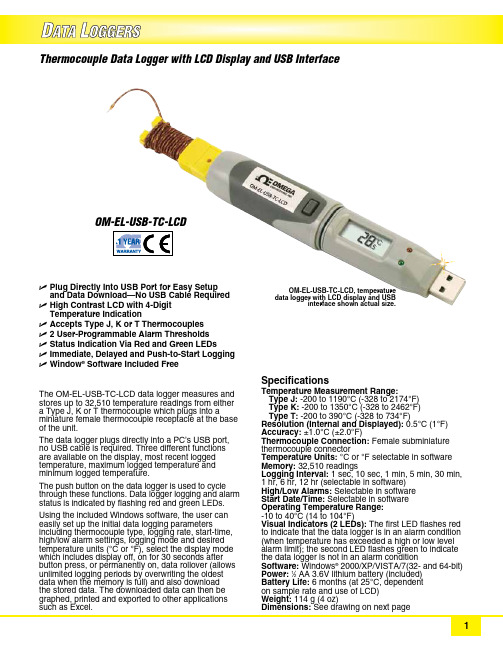
U P lug Directly Into USB Port for Easy Setup and Data Download—No USB Cable RequiredU H igh Contrast LCD with 4‑Digit Temperature IndicationU A ccepts Type J, K or T ThermocouplesU 2 User‑Programmable Alarm ThresholdsU S tatus Indication Via Red and Green LEDsU I mmediate, Delayed and Push‑to‑Start LoggingU Window ® Software Included FreeThe OM‑EL‑USB‑TC‑LCD data logger measures and stores up to 32,510 temperature readings from either a Type J, K or T thermocouple which plugs into a miniature female thermocouple receptacle at the base of the unit.The data logger plugs directly into a PC’s USB port, no USB cable is required. Three different functions are available on the display, most recent logged temperature, maximum logged temperature and minimum logged temperature.The push button on the data logger is used to cycle through these functions. Data logger logging and alarm status is indicated by flashing red and green LEDs.Using the included Windows software, the user can easily set up the initial data logging parameters including thermocouple type, logging rate, start‑time, high/low alarm settings, logging mode and desired temperature units (°C or °F), select the display mode which includes display off, on for 30 seconds after button press, or permanently on, data rollover (allows unlimited logging periods by overwriting the oldest data when the memory is full) and also download the stored data. The downloaded data can then be graphed, printed and exported to other applications such as Excel. Thermocouple Data Logger with LCD Display and USB InterfaceOM-EL-USB-TC-LCDSpecifications Temperature Measurement Range:T ype J: ‑200 to 1190°C (‑328 to 2174°F) Type K: ‑200 to 1350°C (‑328 to 2462°F) Type T: ‑200 to 390°C (‑328 to 734°F)Resolution (Internal and Displayed): 0.5°C (1°F)Accuracy: ±1.0°C (±2.0°F)Thermocouple Connection: Female subminiature thermocouple connector Temperature Units: °C or °F selectable in software Memory: 32,510 readings Logging Interval: 1 sec, 10 sec, 1 min, 5 min, 30 min, 1 hr, 6 hr, 12 hr (selectable in software)High/Low Alarms: Selectable in software Start Date/Time: Selectable in software Operating Temperature Range: ‑10 to 40°C (14 to 104°F)Visual Indicators (2 LEDs): The first LED flashes red to indicate that the data logger is in an alarm condition (when temperature has exceeded a high or low level alarm limit); the second LED flashes green to indicate the data logger is not in an alarm condition Software: Windows ® 2000/XP/VISTA/7(32‑ and 64‑bit)Power: 1⁄2 AA 3.6V lithium battery (included)Battery Life: 6 months (at 25°C, dependent on sample rate and use of LCD)Weight: 114 g (4 oz)Dimensions: See drawing on next pageOM‑EL‑USB‑TC‑LCD, temperature data logger with LCD display and USB interface shown actual size.Ordering Example: OM-EL-USB-TC-LCD , thermocouple data logger with LCD display and USB interface, OCW-3, OMEGACARE SM 3-year extended warranty (adds 3 years to standard 1 year warranty), and OM-EL-BATT replacement battery.Windows ® Software setup screenWindows ® Software shows data in graphical format 134.5 (5.3)69.2 (2.7)56.8 (2.2) 3.5(0.14)2.8(0.11)1.1(0.04) 4.4 (0.174)22.3(0.88)23.9(0.94)24.1(0.95)25.3(0.99)Includes a free 1 m (40") Type K insulated beaded wire thermocouple with subminiature connector and wire spool caddy. Order a Spare! Model No. SC-GG-K-30-36.FREE Thermocouple Included!Dimensions: mm (in)OMEGACARE SM extended warranty program is available for models shown on this page. Ask your sales representative for full details when placing an order. OMEGACARE SM covers parts, labor and equivalent loaners.。
温度数据记录仪产品说明书
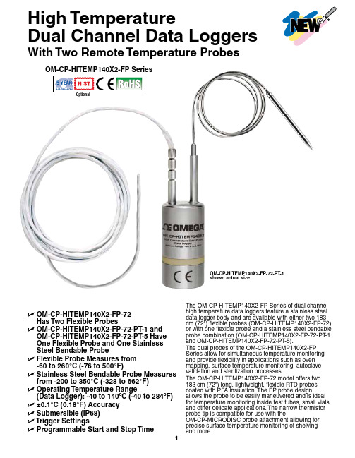
High TemperatureDual Channel Data Loggers With Two Remote Temperature ProbesOptionalU O M-CP-HITEMP140X2-FP-72Has Two Flexible ProbesU O M-CP-HITEMP140X2-FP-72-PT-1 and OM-CP-HITEMP140X2-FP-72-PT-5 HaveOne Flexible Probe and One StainlessSteel Bendable ProbeU F lexible Probe Measures from-60 to 260°C (-76 to 500°F)U S tainless Steel Bendable Probe Measures from -200 to 350°C (-328 to 662°F)U O perating Temperature Range(Data Logger): -40 to 140ºC (-40 to 284ºF) U±0.1°C (0.18°F) AccuracyU S ubmersible (IP68)U T rigger SettingsU P rogrammable Start and Stop Time The OM-CP-HITEMP140X2-FP Series of dual channel high temperature data loggers feature a stainless steel data logger body and are available with either two 183 cm (72") flexible probes (OM-CP-HITEMP140X2-FP-72) or with one flexible probe and a stainless steel bendable probe combination (OM-CP-HITEMP140X2-FP-72-PT-1 and OM-CP-HITEMP140X2-FP-72-PT-5).The dual probes of the OM-CP-HITEMP140X2-FP Series allow for simultaneous temperature monitoring and provide flexibility in applications such as oven mapping, surface temperature monitoring, autoclave validation and sterilization processes.The OM-CP-HITEMP140X2-FP-72 model offers two 183 cm (72") long, lightweight, flexible RTD probes coated with PFA insulation. The FP probe design allows the probe to be easily maneuvered and is ideal for temperature monitoring inside test tubes, small vials, and other delicate applications. The narrow thermistor probe tip is compatible for use with theOM-CP-MICRODISC probe attachment allowing for precise surface temperature monitoring of shelvingOM-CP-HITEMP140X2-FP-72-PT-1shown actual size.The OM-CP-HITEMP140X2-FP-72-PT-1 andOM-CP-HITEMP140X2-FP-72-PT-5 models feature a 61 cm (24") stainless steel bendable probe with the option of either a 2.5 cm (1") or 12.7 cm (5") probe tip (sheath). The stainless steel probe can be bent, angled, and coiled in any direction and formed into position as needed. The sharp probe tip allows for easy insertion and has an extended measurement range of-200 to 350°C (-328 to 662°F).The body of the OM-CP-HITEMP140X2-FP data loggers are capable of operating in temperatures from -40 to 140°C (-40 to 284°F). All models have the capacity to store up to 32,700 time and date stamped readings and feature non-volatile solid state memory that will retain data even if the battery becomesdischarged.The OM-CP-HITEMP140X2-FP utilizes the latest software. The device can be started, stopped, and data can be downloaded quickly and easily. Once in the software, the data can be reviewed in graphic, tabular, or summary form as well as exported to Excel® for further analysis and calculations.The OM-CP-MULTIMOUNTis a versatile mount orstand for use with theOM-CP-HITEMP140 series ofdata loggers. It can be usedto stabilize a logger inside anautoclave, or screwed to aflat surface to create ananchored base. Made of316 stainless steel, theOM-CP-MULTIMOUNTis able to withstandtemperatures up to150°C (302°F) making it ideal for use in autoclavesterilization processes.All modelsshown smallerthan actual size.OM-CP-HITEMP140X2-FP-72OM-CP-HITEMP140X2-FP-72-PT-5OM-CP-IFC400, Windows® software displays datain graphical or tabular format.SPECIFICATIONSTEMPERATURETemperature Sensor:OM-C -HITEM 140X2-F : Flexible RTD probe O M-CP -HITEMP 140X2-FP -P T: Flexible RTD Probe and bendable RTD probeProbe Measurement Range:Flexible Probe: -60 to 260°C (-76 to 500°F) Bendable Probe: -200 to 350°C (-328 to 662°F)Temperature Resolution: 0.01°C (0.02°F)Calibrated Accuracy: ±0.1°C (±0.18°F)GENERALReading Rate: 1 reading every second up to 1 reading every 24 hoursMemory: 32,767 readings Start Modes:• Software programmable immediate start • Delay start up to 18 months in advanceStop Modes: Manual or Timed (specific date and time)Real Time Recording: May be used with PC to monitor and record data in real timePassword Protection: An optional password may beprogrammed into the device to restrict access to configuration options. Data may be read out without the password Readings in Trigger Settings Mode: 16,383 readingsTrigger Settings: High and Low limits may be set. Once data meets or exceed set limits, the device will record to memory. Bi-level start and stop triggers can also be programmed. Users can specify the number of readings to take after the device triggers. (T riggering on channel 1 only)Memory Wrap Around: Y es (software selectable)Battery Type: 3.6V high-temperature lithium battery included; user replaceableBattery Life: 1 year typical [1 minute reading rate at 25°C (77°F)]Calibration: Digital calibration through softwareOM-CP-IFC406 multiplexer data logger interface, shown smaller than actual size (data loggers sold separately).Calibration Date: Automatically recorded within device Data Format: Date and time stamped °C, °F , °R, K Time Accuracy: 1 minute/month @ 25°C (77°F) • 1 minute/month at 25°C (77°F)Computer Interface: OM-CP-IFC400 USB docking station or OM-CP-IFC406 multiplexer interface required; 125,000 baudSoftware: Windows XP SP3/Vista/7 and 8 (32- and 64-bit)Operating Environment: -40 to 140°C (-40 to 284°F), 0 to 100% RH, 0.002 to 100 psia IP Rating: IP68Dimensions (Body): 48 H x 24.6 mm dia (1.89 x 0.97")Dimensions (Probe):OM-C -HITEM 140X2-F -72: Flexible robe: 1829 L x 2.5 mm dia (72 x 0.1") OM-CP-HITEMP140X2-FP-72-PT -1 with 2.5 cm (1") Bendable robe: robe Tip: 42 L x 3.2 mm dia (1.7 x 0.125") Bendable ortion: 559 L x 1.6 mm dia (22 x 0.062") OM-CP-HITEMP140X2-FP-72-PT -5 with 12.7 cm (5") Bendable robe: robe Tip: 121 L x 3.2 mm dia (4.8 x 0.125") with25 L x 4.8 mm dia (1 x 0.188") handle Bendable ortion: 559 L x 1.6 mm dia (22 x 0.062")Weight:OM-C -HITEM 140X2-F -72: 115 g (4.1 oz) OM-C -HITEM 140X2-F -72-T: 110 g (3.9 oz)Materials: Body: 316 stainless steel, PEEK Bendable Probe: 316 stainless steel Flexible Probe: PFA insulated cableOM-CP-MICRODISC surface temperature probe attachment (shown with probepackage and OM-CP-IFC406 multiplexer. OM-CP-IFC400 required for data logger operation. Both models sold separately.Ordering Example: OM-CP-HITEMP140X2-FP-72-CERT high temperature data logger with two 183 cm (72") flexible probes and NIST calibration certificate.To OrderModel No.DescriptionOM-CP-HITEMP140X2-FP-72-PT -5 shown smaller than actual size.。
DTU1706 USB一次性PDF温度记录仪说明书
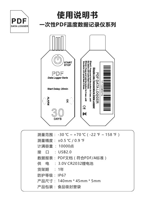
一次性PDF 温度数据记录仪系列使用说明书PDF DATA LOGGER 测量范围: -30 ℃ ~ +70 ℃(-22 ℉ ~ 158 ℉)测量精度: ±0.5 ℃ / 0.9 ℉计满容量 : 10000点接 口 : USB2.0数据报表: PDF 文档(符合PDF/A 标准)供 电 : 3.0V CR2032锂电池货架期 : 1年防护等级: IP67产品尺寸: 140mm * 45mm * 5mm产品包装: 食品级封塑袋30DAYSOKALARMSTARTSTOPStart Delay: 20minData Logger SerisPDF按住按键5秒钟以开始记录,ALARM LED快速闪烁5次表示设备启动成功。
计满自动停止,或者按住按键5秒钟,ALARM LED 快速闪烁3次表示设备停止记录。
撕开塑胶袋,露出USB接口。
将设备插入电脑USB口,等待设备自动生成PDF文件,设备生成PDF时OK LED和ALARM LED交替闪烁。
当电脑系中出现U盘设备时,打开U盘,直接读取PDF报表。
ALARM快速闪烁1次 记录中快速闪烁2次 没有开始记录快速闪烁3次 计满或已停止记录OK快速闪烁1次 电池电量低快速闪烁3次 记录停止指示快速闪烁5次 记录开始指示OK + ALARM交替闪烁 设备正在生成PDF文档同时常亮 设备跟计算机已连接LED状态 指示内容30DAYSOKALARMSTARTSTOP Start Delay: 20min Single Use Temperature Data LoggerData Logger SerisStart:5Press and hold the button forsec. untilthem LED quick flashtimes.alar5Press and hold the button for 3 sec. until Stop: the LED quick flash 3 times.alarm PDF DATA LOGGERPDFPDF Single Use Temperature Data LoggerUser ManualPDFDATA LOGGERMeasure Range: -30 ℃ ~ +70 ℃(-22 ℉ ~ 158 ℉)Accuracy : ±0.5 ℃ / 0.9 ℉Capacity : 10000 GroupInterface : USB2.0Data Report : PDF File (PDF / A standard)Power Supply : 3.0V CR2032Li BatteryValid period : 1 YearIngress Protection Rating: IP67Size : 140mm * 45mm * 5mmPackage : Food-grade sealed plastic bag30DAYSOKALARMSTARTSTOPStart Delay: 20minData Logger SerisPDFPress button for 5 seconds tostart recording, ALARM LEDflashing 5 times to indicatestart successfully.Stop automatically when memoryfull, or perss button for 5 secondsto stop recording, ALARM LEDflashing 3 times to indicate stopsuccessfully.Tear the plastic bag and exposethe USB port.Insert the device into the computerUSB port, wait for the device togenerate PDF report. The OK LEDand ALARM LED flash alternatelyin this period. When the computersystem appears Udisk, open it andget the PDF report.ALARMQuick Flash 1 time RecordingQuick Flash 2 times Not startedQuick Flash 3 times Stoped or Memory Full OKQuick Flash 1 time Low BatteryQuick Flash 3 times Stop Recording indicationQuick Flash 5 times Start Recording indication OK + ALARMAlternating flashing Generating PDF reportAlways ON Connected to the computer LED Status Indication。
TP700多路温度记录仪说使用明书
� � � �
基本误差小于±0.2%F·S,数字显示范围-999.99~1999.99 测量分辨力:1/60000,24 位 AD 转换器 实时曲线记录间隔 1 秒~9999 秒,对应整屏曲线时间 30 秒~300 分 追忆曲线记录间隔从 1 秒到 9999 秒连续可设
3.2 输入信号
输入信号包括直流电流,直流电压,热电阻,热电偶,远传压力表五类, 通 过按键输入选择。隔离万能输入,无需跳线器。 直流电流: (4~20)mA, (0~10)mA, (0~20)mA; 直流电压: (0~5)V ,(0~10)V,-20~+20mA ; 热电阻:Pt100,Cu50; 热电偶:K,S,R,B,N,E,J,T ; 其它输入信号或分度号需在订货时注明。
5.3 开机画面
屏幕会显示点击屏幕进入启动属性窗口,这时我们不需要去点击屏幕,让屏 幕直接进入显示开机启动画面。
5.4 显示界面
11
TP700 多路温度记录仪 显示界面可以对当前的状况有比较全面的了解,包括测量名称,测量值,工 程量单位,报警指示,报警输出状态等。画面的形式如下:
5.5(数显)数字显示界面
2
TP700 多路温度记录仪
二、 功能特点
本产品显示信息量大、界面友好、操作简单,下面是主要功能特点:
� 不需要笔和纸记录,日常维护工作量非常小,运行费用低; � 采用高亮度触控彩色 TFT 液晶屏,CCFL 背光、画面清晰; � 采用 ARM 微处理器,可同时实现多路(仪器内部最高 64 路信号采集、
TP700 多路温度记录仪说明书
目
一、 二、 三、 四、 五、 六、 七、 八、
录
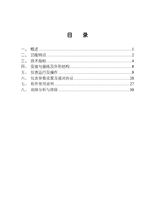
概述...................................................................................................... 1 功能特点 ............................................................................................. 2 技术指标 ............................................................................................. 4 安装与接线及外形结构 ....................................................................6 仪表运行及操作.................................................................................9 仪表参数设置及通讯协议..............................................................20 软件使用说明 ...................................................................................27 故障分析与排除...............................................................................30
Temp101A 温度数据记录仪说明书
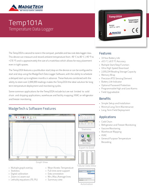
The Temp101A is second to none in the compact, portable and low cost data logger class. This device can measure and record ambient temperature from -40 °C to 80 °C (-40 °F to +176 °F) and is approximately the size of a matchbox which allows for easy placement even in tight spaces.The Temp101A features a pushbutton start/stop on the device or can be configured to start and stop using the MadgeTech Data Logger Software, with the ability to schedule a delayed start up to eighteen months in advance. These features combined with the ability to store over 2,000,000 readings makes the Temp101A the ideal solution for long term temperature deployment and monitoring cycles.Some common applications for the Temp101A include but are not limited to cold chain and shipping applications, warehouse and facility mapping, HVAC or refrigerator and freezer monitoring.• Multiple graph overlay • Statistics• Digital calibration • Zoom in/ zoom out• Lethality equations (F0, PU)MadgeTech 4 Software FeaturesStatisticsGraph ViewTabular Data ViewAutomation• Mean Kinetic Temperature • Full time zone support • Data annotation• Min./Max./Average lines • Summary viewFeatures• 10 Year Battery Life• ±0.5 °C (±0.9 °F) Accuracy • Multiple Start/Stop Function • Ultra High Speed Download• 2,095,104 Reading Storage Capacity • Memory Wrap• Precision RTD Sensing Element • Battery Life Indicator• Optional Password Protection• Programmable High and Low Alarms •Field UpgradeableBenefits• Simple Setup and Installation • Minimal Long-Term Maintenance • Long-Term Field DeploymentApplications• Cold Chain• Refrigerator and Freezer Monitoring • Vaccine Monitoring • Warehouse Mapping • HVAC•General Purpose Temperature RecordingSPECIFICATIONSSpecifications are subject to change without notice. Specific warranty remedy limitations apply. Call (603) 456-2011 or go to for details.6 Warner Road, Warner, NH 03278 (603) 456-2011 | DOC-1214009-00 REV 10 2021.02.01Ordering InformationBATTERY WARNING: FIRE, EXPLOSION AND SEVERE BURN HAZARD. DO NOT RECHARGE, DISASSEMBLE, HEAT ABOVE 100 °C (212 °F), INCINERATE, CRUSH, OR EXPOSE CONTENTS TO WATER.。
温湿度记录仪操作流程说明书
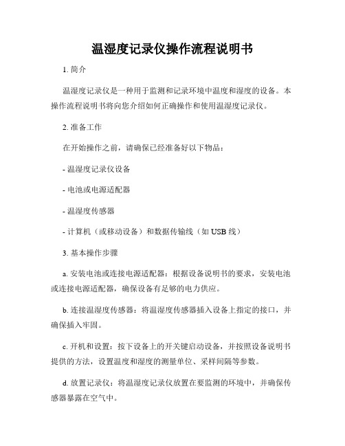
温湿度记录仪操作流程说明书1. 简介温湿度记录仪是一种用于监测和记录环境中温度和湿度的设备。
本操作流程说明书将向您介绍如何正确操作和使用温湿度记录仪。
2. 准备工作在开始操作之前,请确保已经准备好以下物品:- 温湿度记录仪设备- 电池或电源适配器- 温湿度传感器- 计算机(或移动设备)和数据传输线(如 USB 线)3. 基本操作步骤a. 安装电池或连接电源适配器:根据设备说明书的要求,安装电池或连接电源适配器,确保设备有足够的电力供应。
b. 连接温湿度传感器:将温湿度传感器插入设备上指定的接口,并确保插入牢固。
c. 开机和设置:按下设备上的开关键启动设备,并按照设备说明书提供的方法,设置温度和湿度的测量单位、采样间隔等参数。
d. 放置记录仪:将温湿度记录仪放置在要监测的环境中,并确保传感器暴露在空气中。
e. 数据记录和存储:温湿度记录仪将按照设置的采样间隔自动记录环境中的温度和湿度数据,并将其存储在内部存储器中。
f. 数据传输:根据需要,将记录仪与计算机或移动设备连接,使用数据传输线将数据传输到计算机或移动设备上的相应软件中进行进一步分析和处理。
g. 数据分析和报告生成:使用相关软件,对传输到计算机或移动设备上的数据进行分析和处理,并生成相应的报告和图表。
4. 注意事项在操作和使用温湿度记录仪时,请注意以下事项:- 请按照设备说明书提供的方法正确操作设备,避免不必要的损坏或故障。
- 请确保温湿度传感器插入牢固,并暴露在要监测的环境中以获得准确的数据。
- 定期检查电池电量,并及时更换电池以确保设备正常运行。
- 在进行数据传输前,请确保设备与计算机或移动设备的连接稳定,并使用正规和可信赖的数据传输线。
- 在数据分析过程中,请根据需要进行准确的数据处理和结果生成。
5. 故障排除如果在使用温湿度记录仪时遇到任何故障或问题,请参考设备说明书提供的故障排除方法,或联系设备供应商寻求帮助和支持。
6. 结束操作在使用完温湿度记录仪后,请将设备关机,并根据需要将其存放在干燥和安全的地方,以防止损坏或丢失。
温度记录仪说明书
CONTENT PageI. SAFETY INFORMATION ----------------- 2 II. FEATURE ------------------------------------- 2 III. GENERAL SPECIFICATION -----------3 IV. NAME AND FUNCTION ------------------ 4 V. OPERATION INSTRUCTIONS:5.1 Setup Menu-----------------------------6 5.2 Measurement ------------------------10 5.3 Print ---------------------------------------12 5.4 Load Thermal Paper -----------------14 5.5 Replace Battery ---------------------15 VI. ATTENTION6.1 Cancel Timed Printing -------------16 6.2 Cancel Timed Recording -----------16 6.3 Master Reset -------------------------17 VII. Software7.1 Installation ---------------------------18 7.2 Introduction --------------------------19servicing not covered in this manual.3. Periodically wipe the case with a dry cloth. Do not use2. Text Print Out.3. The easy access menu buttons and text area in the LCDdisplay provide a simple and intuitive hierarchical menu operation for system setup.4. Built in system clock.5. Photo coupler isolated RS-232 interface.6. With Windows software.7. 32,000 Records Data Logger.8. T1 & T2 dual display with swapping display area.9. MAX / MIN function.10. REL function.2I. GENERAL SPECIFICATION1. Measurement Range: TYPE K -200¡C ~ 1370¡C -328¡F ~ 2498¡F TYPE J -200¡C ~ 760¡C -328¡F ~1400¡F2. Accuracy: -200¡C ~ 1370¡C –0.1% + 0.8¡C-328¡F ~ 2498¡F –0.1% + 1.6¡F3. Resolution: 0.1¡C / 0.1¡F4. Sample Rate: 2 times / second5. Input Protection: 60V DC or 24Vrms AC6. Data Logger: 32,000 Records7. Storage Condition: -10¡C ~ 60¡C (14¡F ~ 140¡F)0 ~ 80% RH8. Operating Condition: 0¡C ~ 50¡C (32¡F ~ 122¡F)0 ~ 80% RH9. Battery: Size AA 1.5V x 6 (alkaline battery)10. AC Adapter: DC 9V ~ 12V , 1A Min11. Thermal Paper: 58mm width, 31_12. Dimension: 242 x 98 x 42mm13. Weight: 580g Approx.14. Accessory: Tool BoxAlkaline Battery Size AA 1.5V x 6Instruction MenuK Type Sensor x 2 (-50¡C ~ 200¡C)Thermal Paper x 2 (31_x 58mm)RS-232 Connection CableWindows Software Disk34V. NAME AND FUNCTIONDC 9VT2T1T2¢X F RELPRINTINST RECFEEDMINMAX C¢X C T1TEMPERATURE RECORDEROPENMENUCMENUINSTPRINTFEEDREC REL MAX MIN¢X C ¢X F T1T2Paper SoltPaper Output Manual Feed Knob Print Head LevelL C DDC 9V JackSetup Panel Function PanelPrint PanelTemperature Sensor Input ConnectorFunction Panel:Setup Panel:Print Panel:Exit without savingEnterBrowse menu or number down Browse menu or number up Paper feed 2/3 inchStart / Stop printingPrint present data Power button¢X C / ¢X F button Record buttonT1 / T2 button Relative readout button MAX / MIN button6V. OPERATION INSTRUCTIONS5.1 Setup MenuPress Menu select button to select menuCMENU MENUTEMPERATURE RECORDEROPENExit without savingEnterBrowse menu or number down Browse menu or number up7Menu itemMenu description Set system clock Set thermocouple typeNote: Thermocouple type must be the same as thetype of sensor.369875421Set system clock Set start/stop printing time and print mode Set Thermocouple Typerecord interval Set start/stop recording time and Clear Datalogger memory Power management setup Alarm limit setupPrinter test printingPrint out setup information1Set time Set date Set year2Select J TypeSelect K Type16VII. Software7.1 InstallationSystem Required:Windows 95 / Windows 98 / Windows MEWindows NT 4.0.Minimum Hardware Required:PC with Pentium 90MHz or higher.32 MB RAM.4X CD-ROM Drive or higher.Recommended resolution 800X600.At least 5 MB byte hard disk space available toinstall TestLink.Installation :1.We recommend close all other applicationbefore installing TestLink.2.Insert the setup CD disc to CD-ROM drive and theinstallation program should start automatically.3.If installation do not start automatically, choose thestart button on the Taskbar and select Run.4.Type E:\SETUP and choose OK, then it will copySE500.exe (executable file) and help file to yourhard disk (default is c:\programfiles\TestLink\SE500).1819.2 IntroductionMain ScreenMain menuTool menuReading display Real time graphReal time list Max/Min/Avgdisplay Main ScreenFile : Open - Open files saved previously from the disk. Save - Save the active window(when the caption baris highlighted) data to the disk. Print - Print the data of the active window(graph or list).Printer Setup - Select printer.Exit - Terminates TestLink program.DataLogger : By opening the D ataLogger Window,the user can load recorded data ofmeter to PC in this window.Real Time Data : Run - Start recording real time data.Stop - Stop recording real time data.Option : Setup Temperature Recorder from PC. COM port : Select PC connector port manually.View : LCD - Open LCD simulation window.Real Time Graph - Open Real-Time Graphwindow to graph the presentdata.Window : Arrange windows Help : On line help.20DataLoggerata Sets ListData ListWhen you have Temperature Recorder meter connected to PC and select "DataLogger" from main menu or click from tool bar to load recorded data from the meter and there will be a progress indicator to show the loading progress. If error occurs, just click "D ataLogger" again.After the data was loaded completely, the top left hand side will show how many data sets were loaded and detail information for each data set (start data, start time,recording rate and record numbers).For examples, the figure below means there are two data sets, set 1 recorded 1325 records and set 2 recorded 19349 records.It will transfer first data set to graph on the right hand side and list data after loading, You can click other data set to view the graph and list of the data set you select.Tutorial Quick StartRecording real time data from PC.1.Power on the Temperature Recorder first and connect it to a PC RS-232 serial port wit the cable,2.Run the Software.3.If the connection is successful the LCD simulation willdisplay the same value as the Temperature Recorder.If fail to connect the meter with PC, it will display "NoConnection" on the LCD simulation window .4.When the connection is successful, select Real TimeData | Run from main menu or click from tool bar,there will be a dialog for you to select record intervaland record numbers and click start button to startrecording.5. When the recorded data numbers reach to theamount you set, it will stop recording, or click to stoprecording .How to save the recorded real time data to a file ?1.Click the window you want to save and the windowwill become active , then choose File | Save frommain menu or click from the tool bar.2.There will be a save dialog window for you to choosethe file name and file type to save.3.There are three types of file name you can choose,they are binary file(*.ghf), text file(*.txt) and EXCELformat file(*.csv). The *.ghf file use much fewer diskspace to save the data than the other two file format,but it can only be used in TestLink SE500. Text filecan be opened by TestLink SE500 and any otherword processor program like word, notepad etc.EXCEL format file can b e opened by TestLink SE500and Microsoft EXCEL.21How to load the recorded data from the memoryofTemperature Recorder and save it to a file ?1. Power on the Temperature Recorder.2. Connect the Temperature Recorder to PC3. Start SE500 program.4. Choose Data Logger from main menu or clickfrom tool bar.5. In reference to Data Logger, see [Page 20] aboutDataLogger.For more operation instruction, please refer to theonline help while executing SE500.22。
S100 温湿度记录仪使用说明手册说明书
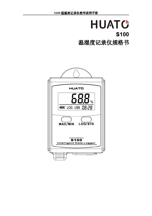
S100温湿度记录仪规格书目录第一章产品介绍 (1)1.1介绍 (1)1.2特性 (1)1.3应用环境 (1)1.4记录仪数据 (2)1.5温湿度记录仪S100-ET/S100-EX外观 (2)1.6温湿度记录仪S100-T/S100-TH外观 (3)1.7S100系列温度记录仪显示屏 (3)1.8S100系列温湿度记录仪显示屏 (4)1.9按键功能介绍 (4)1.10设备状态说明 (4)第二章软件使用指南 (7)2.1计算机硬件的要求 (7)2.2USB驱动安装 (7)2.3LogPro软件使用 (9)2.3.1读取和设置记录仪属性 (9)2.3.2参数设置说明 (10)2.3.3查看数据 (10)2.3.4删除数据 (11)3.1液晶屏显示暗淡 (12)3.2日期&时间错误 (12)3.3软件运行错误 (12)第一章产品介绍1.1介绍华图S100系列记录仪是华图公司最新推出的用于疫苗、冷藏运输、低温冷库等场所的具有国内领先水平的温度测量仪器,采用原装进口之温湿度传感器,精度高,一致性非常好,两节1.5V7号电池供电,连续工作时间达6个月以上,是国家技术监督总局认可的计量仪器。
1.2特性(1)外形小巧精致,使用方便;(2)传感器由瑞士生产,精度高;(3)2节1.5V7号电池可以工作6个月以上,25℃环境(采样间隔60秒,记录间隔300秒);(4)主机尺寸:57x92x20mm;(5)LCD屏幕尺寸:37x17mm;(6)温度和湿度外探针直径:16mm;(7)温度外探头直径:6mm;1.3应用环境(1)疫苗(2)冷藏运输(3)低温冷库(4)工作及生活区域(5)超市1.4记录仪数据1.5温湿度记录仪S100-ET/S100-EX外观LCD显示区型号标签LOG/STD:记录和开关机按键电池盖,打开可更换电池MIN/MIN:最大最小值查看按键USB接口外置传感器接口外置温湿度传感器(S100-EX/S100-EX+)挂孔外置温度传感器(S100-ET/S100-ET+)1.6温湿度记录仪S100-T/S100-TH外观LCD显示屏挂孔LOG/STD按键型号标签MAX/MIN按键电池盖传感器USB端口1.7S100系列温度记录仪显示屏温湿度数值显示区域USB连接标志记录过程中的最大值显示年-月日-时分切换显示记录过程中的最小值华氏度单位符号电池电量摄氏度单位符号记录状态标志1.8S100系列温湿度记录仪显示屏温湿度数值显示区域USB连接标志记录过程中的最大值显示年-月日-时分切换显示记录过程中的最小值湿度单位符号电池电量华氏度单位符号记录状态标志摄氏度单位符号1.9按键功能介绍:进行当前值与记录过程中的最大值、最小值切换(数值锁定);:设备关机时,长按5S后开机进入待机模式,再按3S进入记录模式;记录模式下,按3S可进入待机模式(仅进入待机模式),在待机模式下,按5S 关闭设备。
TempaChek-DL 温度数据记录仪说明书
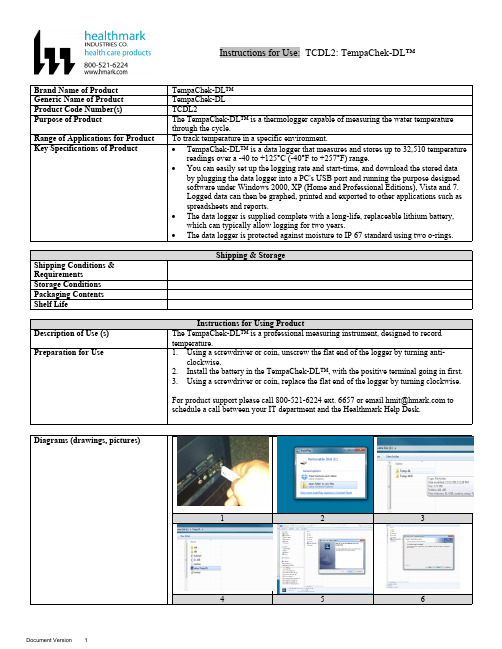
Instructions for Use: TCDL2: TempaChek-DL™Brand Name of Product TempaChek-DL™Generic Name of Product TempaChek-DLProduct Code Number(s)TCDL2Purpose of Product The TempaChek-DL™ is a thermologger capable of measuring the water temperaturethrough the cycle.Range of Applications for Product To track temperature in a specific environment.Key Specifications of Product∙TempaChek-DL™ is a data logger that measures and stores up to 32,510 temperaturereadings over a -40 to +125°C (-40°F to +257°F) range.∙You can easily set up the logging rate and start-time, and download the stored databy plugging the data logger into a PC's USB port and running the purpose designedsoftware under Windows 2000, XP (Home and Professional Editions), Vista and 7.Logged data can then be graphed, printed and exported to other applications such asspreadsheets and reports.∙The data logger is supplied complete with a long-life, replaceable lithium battery,which can typically allow logging for two years.∙The data logger is protected against moisture to IP 67 standard using two o-rings.123456789 1012 131415 161718 192020aSteps for Use of Product 1.Insert software flash drive into USB port on your computer.2.Select “Open folder to view files”.3.Next select folder “Temp-DL”.4.Then select the icon that reads, “Set up Temp DL”.5.Install window will be prompt open, click “Install”.6.Then click “Next”.7.When installation is finished, select “Finished” when window is prompted open.8.Unscrew cap of the TempaChek-DL™ Datalogger.9.Insert the TempaChek-DL into a free USB port on your computer.10.The computer will automatically detect the presence of the TempaChek-DL™ andstart the hardware installation process.11.Double-click the EasyLog USB icon on your desktop to launch the control software.You will be presented with three options on the Main Screen.12.Click on the green button to set up and start the TempaChek-DL™ Data Logger andfollow the setup procedure:B Data Logger Name, Temperature Scale and Sample Rate: - enter the LoggerName, - select the Temperature Scale, - select the Sample Rate, - then click “Next”.a.Note: If you are using this Data Logger for the first time, then it maycontain some sample data, in which case you will receive a warningmessage. Click “OK” to continue.14.Logger Options: - select whether the logger should stop saving data when full orbegin overwriting the oldest data. Then click “Next”.15.Setting alarm levels for the USB Data Logger: - select the Alarms, if required, -select the Alarm Trigger Levels for any selected alarms, - select Hold for anyselected alarms, - then click “Next”.16.Setting the start time and date: - either click Finish if you want to start loggingimmediately or - select the Start Time and Start Date for logging to commence, andthen click “Finish”. The summary screen will now appear.17.Remove the TempaChek-DL™ from the computer and place it in the location whereyou want to measure temperature.a.Note: If you leave the TempaChek-DL™ connected to your PC, the DataLogger will operate at an elevated temperature, due to a self-heating effect.This will cause the Data Logger to record erroneous temperature readings.If the Data Logger is connected to the USB port for a long time (e.g. 15minutes), then you should allow time for the Data Logger to cool down afterdisconnecting it from the USB port.18.Click on the “red” button to stop the datalogger and download and stored data.a.You will be asked to confirm that you wish to stop the USB Data logger,click “yes”.19.A window will pop up to show that the Data Logger has stopped. It will also displaythe name and amount of readings stored.20.Save the file under a suitable file name.a.The data will remain in the logger’s memory until it has been set up again. Interpretation of ResultsContraindications of Test ResultsDocumentationSpecial Warnings and Cautions∙When the TempaChek-DL™ is connected to the USB port, the battery inside theData Logger is discharged at a higher rate than normal. To conserve battery life, donot leave the TempaChek-DL™ connected to the USB port for a prolonged period oftime.∙The TempaChek-DL™ is a professional measuring instrument, designed to recordTEMPERATURE. Care must be taken when:o 1. Removing the logger from extreme environment- The logger is metal andwill retain heat or will remain cold when it has been removed from theenvironment under measurement. Personal protection, such as suitable heatresistant gloves or tools must be used to remove the logger from anyenvironment. See data sheet for maximum and minimum temperatures thatthe logger can be used in.o 2. Replacing batteries- Always operate TempaChek-DL™ and replace itsbatteries according to the instructions.∙The TempaChek-DL™ will work in extreme temperatures. However, many batterieswill not work at these extremes. Always ensure the specific battery as detailed byHealthmark is used. Serious injury can occur if the incorrect battery is used.∙TempaChek-DL™ is not authorized for use as a critical component in life supportdevices or systems.DisposalRelated Healthmark ProductsOther Product Support Documents For more information go to “Help” file contents on the software installation flash drive. Reference Documents ProFormance™ Brochure, ProFormance™ Price ListCustomer Service Contact Healthmark Industries Company, Inc.18600 Malyn Blvd.Fraser, MI 480261-586-774-7600********************。
data test 温度记录仪说明书
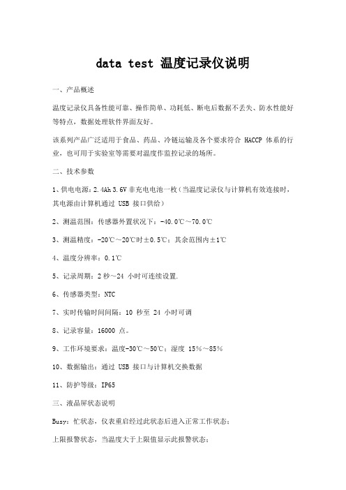
data test 温度记录仪说明一、产品概述温度记录仪具备性能可靠、操作简单、功耗低、断电后数据不丢失、防水性能好等特点,数据处理软件界面友好。
该系列产品广泛适用于食品、药品、冷链运输及各个要求符合 HACCP体系的行业,也可用于实验室等需要对温度作监控记录的场所。
二、技术参数1、供电电源:2.4Ah 3.6V非充电电池一枚(当温度记录仪与计算机有效连接时,其电源由计算机通过 USB 接口供给)2、测温范围:传感器外置状况下:-40.0℃~70.0℃3、测温精度:-20℃~20℃时±0.5℃;其余范围内±1℃4、温度分辨率:0.1℃5、记录周期:2秒~24 小时可连续设置.6、传感器类型:NTC7、实时传输时间间隔:10 秒至 24 小时可调8、记录容量:16000 点。
9、工作环境要求:温度-30℃~50℃;湿度 15%~85%10、数据输出:通过 USB 接口与计算机交换数据11、防护等级:IP65三、液晶屏状态说明Busy:忙状态,仪表重启经过此状态后进入正常工作状态;上限报警状态,当温度大于上限值显示此报警状态;下限报警状态,当温度小于下限值显示此报警状态Wait:记录未启动状态,可持续按键 5 秒启动记录Record:处于记录状态 End:记录停止状态Max:已记录数据的最大值 Min:已记录数据的最小值Act:当前数据 Log:历史数据(最大值、最小值、已记录容量)EE:传感器故障状态℃:温度单位电池容量电量表显示蓝色表明电量剩余25%~100%电量表显示黄色表明电量剩余10%~25%电量表显示红色表明电量剩余<10%(建议更换电池)四、主要功能该仪表可对记录仪属性进行设置,包括用户信息、仪表站号、报警上下限参数;工作状态指示;单键操作,状态指示灯可指示各工作状态、可启动记录、可选择停止记录;符合 HACCP 的要求;温度传感器可内置亦可外置(出厂配置为外置传感器)。
汤姆斯 温度记录仪 TC-9200 使用说明书
1、前言谢谢您的惠顾!仔细阅读本说明书。
1.3、注意事项·当您收到汤姆斯的产品后,请先检查仪表外观是否有损坏和仪表的型号是否与您的定货相符,若有出现上述的问题请立即与本公司取得联系。
·请在了解了仪表的接线和操作后再测试或者安装仪表,仪表初次使用将需要较长时间初始化(大概需要3到9分钟左右)。
·请在仪表允许的工作条件下使用仪表。
一般情况下用户不要擅自拆开仪表,以免发生危险;如仪表出现故障,请先与本公司联系,在技术人员允许和指导下方可拆开仪表。
·请不要用有机溶液清洗LCD 屏幕,以免损伤屏幕。
·仪表每年应进行一次计量检定,如果仪表误差超出范围,通常都是由于潮湿、灰尘或腐蚀气体所导致,可对仪表内部进行清洁及干燥处理,通常这样就能解决问题。
如仍不能解决问题请与本公司技术人员联系。
�采用128×64点阵LCD ,宽视角,高亮度,高对比度。
�全中文菜单设计,画面直观,信息丰富,人机界面友好,易学易用,操作快捷。
�采用贴片技术(SMT),设计更加简洁。
�多通道输入,支持多种输入类型,现场配置灵活方便。
�热电偶、热电阻输入采用非线性修正,测量精度高,稳定性好。
�存储容量大,基本配置2MB (用户有特殊需要可再增加),超长记录时间。
2.2、技术指标●输入规格(一台仪表即可兼容):热电偶:K 、S 、E 、J 、T 、B 、N 热电阻:Cu50、Pt100、Cu100线性电压:0-5V 、1-5V 等线性电流:0-10mA 、4-20mA 等(若订货时未注明需外接500Ω或250Ω精密电阻)扩充规格:在保留上述输入规格基础上,允许用户指定一种额外输入规格(非线性输入可能需要提供分度表)●测量范围:K (-50~1300℃)、S (-50~1700℃)、T (-200~350℃)、E (0~800℃)、J (0~1000℃)、B (300~1800℃)、N (0~1300℃)、Wre325(0~2300℃)Cu50(-50~150℃)、Pt100(-200~600℃)、Cu100(-50~150℃)线性输入:-29999-29999由用户定义●测量精度:0.2级(热电阻、线性电压、线性电流及热电偶输入且采用铜电阻补偿或冰点补偿冷端时);0.2%FS ±2.0℃(热电偶输入且采用仪表内部元件测温补偿冷端时)●响应时间:≤1秒(设置数字滤波参数等于0时)●报警功能:上限、上上限、下限、下下限等4种方式,最多可带2路报警输出,可共用。
海康威视 HC-2000 温度记录仪说明书
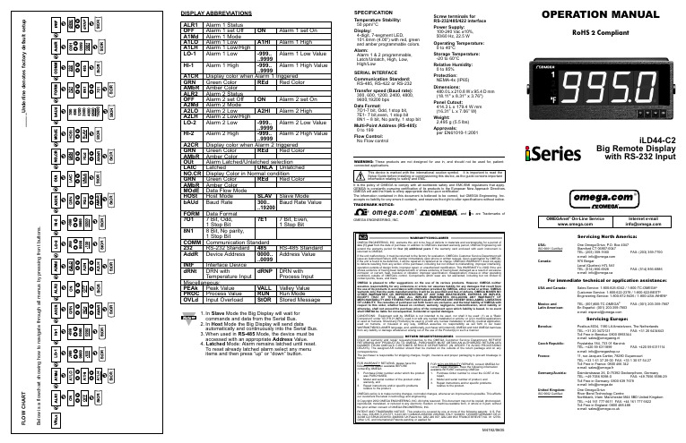
SPECIFICATIONTemperature Stability:50 ppm/°C Display:4-digit, 7-segment LED,101.6mm (4.00”) with red, green and amber programmable colors.Alarm:Alarm 1 & 2 programmable, Latch/Unlatch, High, Low, High/LowSERIAL INTERFACECommunication Standard:RS-485, RS-422 or RS-232Transfer speed (Baud rate):300, 600, 1200, 2400, 4800, 9600,19200 bps Data Format:7O1-7 bit, Odd,1stop bit,7E1- 7 bit,even, 1 stop bit8N1 – 8 bit, No parity, 1 stop bit Multi-Point Address (RS-485):0 to 199Flow Control:No Flow controlScrew terminals forRS-232/485/422 interface Power Supply:100-240 Vac ±10%,50/60 Hz, 22.5 WOperating Temperature:0 to 40°CStorage Temperature:-20 to 60°CRelative Humidity:0 to 85%Protection:NEMA-4x (IP65)Dimensions:480.0L x 210.8W x 95.4D mm (18.11" x 8.31" x 3.76")Panel Cutout:414.3 L x 179.4 W mm (16.31” L x 7.06” W)Weight:2,495 g (5.5 lbs)Approvals:per EN61010-1:2001DISPLAY ABBREVIATIONSALR1Alarm 1 Status OFF Alarm 1 set Off ON Alarm 1 set On A1Md Alarm 1 Mode A1LO Alarm 1 LowA1HIAlarm 1 HighA1LH Alarm 1 Low/High LO-1Alarm 1 Low-999..Alarm 1 Low Value ..9999HI-1Alarm 1 High -999..Alarm 1 High Value..9999A1CR Display color when Alarm 1 triggered GRN Green Color REd Red Color AMbR Amber Color ALR2Alarm 2 Status OFF Alarm 2 set Off ON Alarm 2 set On A2Md Alarm 2 Mode A2LO Alarm 2 Low A2HI Alarm 2 High A2LH Alarm 2 Low/High LO-2Alarm 2 Low -999..Alarm 2 Low Value..9999HI-2Alarm 2 High -999..Alarm 2 High Value..9999A2CR Display color when Alarm 2 triggered GRN Green Color REd Red Color AMbR Amber Color OUt Alarm Latched/Unlatched selection LAtC Latched UNLA Unlatched NO.CR Display Color in Normal condition GRN Green Color REd Red Color AMbR Amber Color MOdE Data Flow Mode HOSt Host Mode SLAV Slave Mode bAUd Baud Rate 300..Baud Rate Value..19200FORM Data Format 7O17 Bit, Odd,7E17 Bit, Even,1 Stop Bit 1 Stop Bit8N18 Bit,No parity,1 Stop BitCOMM Communication Standard 232RS-232 Standard 485RS-485 Standard AddR Device Address 0000..Address Value..0099INtF Interface Device dRNt DRN with dRNP DRN withTemperature Input Process InputMiscellaneous:PEAk Peak Value VALL Valley Value PROC Process Value RUN Run Mode OVLd Input Overload StOR Stored Message1.In Slave Mode the Big Display will wait forcommands and data from the Serial Bus.2.In Host Mode the Big Display will send dataautomatically and continuously into the Serial Bus.3.When used in RS-485Mode, the device must be accessed with an appropriate Address tched Mode: Alarm remains latched until reset.To reset already latched alarm select any menu items and then press “up” or “down” button.M4192/0605WARNING:These products are not designed for use in, and should not be used for, patient-connected applications.It is the policy of OMEGA to comply with all worldwide safety and EMC/EMI regulations that apply. OEMGA is constantly pursuing certification of its products to the European New Approach Directives. OMEGA will add the mark to every appropriate device upon certification.The information contained in this document is believed to be correct, but OMEGA Engineering, Inc. accepts no liability for any errors it contains, and reserves the right to alter specifications without notice.TRADEMARK NOTICE:®,®,, andare Trademarks ofOMEGA ENGINEERING, INC.®Mounting Big Display on Bail:1.Mark the location of mounting screws on the flat surface.2. Be sure to leave enough room around the bail to allow for removal and rotation of the display.3.The display can be rotated for the best viewing angle.Disassembly Instruction:DESCRIPTION:The iLD44 is a 4-digit master/slave display providing remote readout from instruments such as programmable controllers, digital panel meters and other instruments with serial output. Communication interfaces supported are RS-232 or RS-485 standards. BothRS-232 or RS-485 are programmable through front panel buttons.The Big Display features a large three color programmable display with the capabitity to change color every time an Alarm is triggered.Refer to the separate Signal Conditioner Manual for your specific Input details.SAFETY:•The instrument is a panel mount device protected in accordance with EN61010-1:2001.EMC:•Whenever EMC is an issue, always use shielded cables. •Never run signal and power wires in the same conduit.•Use signal wire connections with twisted-pair cables.•Install Ferrite Bead(s) on signal wire close to the instrument if EMC problems persist.MOUNTINGMounting Big Display Through Panel:ing the panel cutout diagram shown above, cut an opening in the panel.2. Remove six screws at the back of Big Display to remove back cover.3.Insert the unit into the opening from the front of the panel, so the gasket seals between the bezel and the front of the panel.4.Align back cover to Big Display and reinstall screws.。
TP700温度记录仪使用说明书(1)
目录一、概述 (1)二、功能特点 (2)三、技术指标 (4)四、安装与接线及外形结构 (6)五、仪表运行及操作 (9)六、仪表参数设置及通讯协议 (20)七、软件使用说明 (27)八、故障分析与排除 (30)一、概述触控数据记录仪以其丰富的显示画面、灵活的操作方式以及强大的记录、运算、控制和管理功能,在各行各业中获得了极其广泛的应用。
本产品吸纳了各种国内外数据记录仪的优点,应用最新的显示技术、微电子技术、数据存储和通讯技术,是一款功能齐全、操作方便、精确可靠、高性价比的产品。
本产品配置丰富,有蓝屏和彩色两种显示屏。
可以接收多种类型的直流电流、电压和电阻信号,实现温度、湿度、压力、液面、流量、成分以及力、力矩、位移等物理量的显示、记录、越限监控、报表生成、数据通讯、信号变送以及流量累计等功能。
本产品主要由触控液晶屏、按键、ARM微处理器为核心的主板、主电源、外供变送器电源、智能通道板、大容量FLASH等构成:可配备不同类型的智能通道板,根据应用要求选择。
内置大容量FLASH,可通过U盘快速将FLASH中的数据转储到计算机中。
内置的FLASH的容量为70M字节,8通道时若20秒记录一次可记录865天,最快1秒记录一次所有通道的数据。
数字显示界面、棒图显示画面、实时曲线画面、追忆曲线画面追忆曲线读数光标功能。
测量、显示基本误差:±0.2% F·S可参数设置多点报警功能。
1二、功能特点本产品显示信息量大、界面友好、操作简单,下面是主要功能特点:不需要笔和纸记录,日常维护工作量非常小,运行费用低;采用高亮度触控彩色TFT液晶屏,CCFL背光、画面清晰;采用ARM微处理器,可同时实现多路(仪器内部最高64路信号采集、记录、显示和报警;采用70MB 大容量的FLASH 闪存芯片存贮历史数据,掉电永不丢失数据;全隔离万能输入,可同时输入多种信号,无需更换模块,直接在仪器上设置即可;显示工程量数据的数值范围更宽可显示6位数值:-999,99~1999.99;可以参数设置、显示工程位号,工程单位,有流量累积;具有闪动报警显示,同时指示各路通道的下下限、下限、上限、上上限报警;8路继电器报警输出(订做产品);显示精度高,基本误差为±0.2% F·S;内置GB2312汉字库,使用全拼输入法输入;支持外接微型打印机,手动打印数据、曲线,自动定时打印数据,满足用户现场打印的需求(订做产品);配备标准USB2.0接口。
HiLOGGER 8420-51、8421-51、8422-51 温度数据记录仪用户说明书

Data LoggersMEMORY HiLOGGERAs demand for multi-channel temperature recording for environmental protec-tion, energy conservation and HACCP activities increase steadily, portability to enable measurement everywhere and at all times, and communications support for connecting to IT (information technology) networks are becoming indispensable capabilities for measurement instruments. Furthermore, at measurement sites, ac-curate measurements are required in severe conditions such as the presence of dif-ferent electrical potentials, hum noise from commercial power lines, and switch-ing noise from inverters. In response to these requirements, we have developed theInternal memory capacity is greatly increased – four times that of previous models!New multi-channel loggers with enhanced noise immunity2● Numerical data logging/recording and trend graph display ● Completely isolated input channelsNo need to worry about potential difference between measure-ment objects● Real-time saving to large capacity memory cardUse a large capacity memory card for long-term data recording ● Data collection to a PC via LAN• Real-time measurements on PCs running 9334 LOGGERCOMMUNICATOR• Data acquisition by FTP client/server functions • Send e-mail notification of anomalies by SMTP• Monitor and control over the Web using HTTP server functionsGet measurement result printouts on site by docking with the 8992 PRINTER UNIT . Record long-period trend graphs and print hard copies of screens.Send control signals to an external device by docking with the 8993 DIGITAL I/O UNIT (available with up to 16 channels). Sixteen logic input channels are also provided. In addition to analog and pulse inputs such as for temperature, 16 points of simultaneous logic signal input are supported.ApplicationsFeaturesch 32ch 31ch 2ch 19329 TERMINAL UNIT (optional)Attached CoverM3 Screw TerminalsThe recommended wire diameter for the instrumentʼs terminal block is 0.32mm (0.0126 inch). Use the Model 9329 TERMINAL UNIT to secure smaller-diameter wire.External Docking Printer External Docking Input-Output unitEnhanced functionality in response to user demands- Main features and product outline -● Four Times More Internal MemoryInternal memory has been increased from 8 to 32 megabytesin the new models, which can now store up to about 16.77 million data points.● Enhanced Noise ImmunityThe circuitry was reviewed from the ground up, and a delta-sigma type A/D converter was incorporated. The effects ● Battery Charging Available During OperationPreviously, the battery could be charged only when the instru-ment was turned off, but it can now be charged while measur-ing. Because of this, if an unexpected power outage occurs during long-term measurement and recording, situations such as measurement discontinuation resulting from battery self discharge can be avoided, significantly improving the reliability of long-term measurement.Improved Accuracy of Internal ClockClock accuracy has been greatly improved (0.2 seconds/dayis the same as the previous Model 8422-01).Chatter Filter Installed for External TriggerThe filter function installed for external triggering preventsmalfunctioning when starting and ending measurement using a mechanical relay.Functions upgraded from former models● Power and Gas• Trend measurement of machinery output/temperature• Watt-hour meter pulse count/output recording of machinery● Electronic Device and Component Manufacturing• Product testing, quality control recording● Automobiles, Trains and Distribution Transportation• Collect the necessary data during their development● Building Maintenance, Factory Facilities• Long-term data acquisition for maintenance • Food-related temperature recording9641 Trigger Output Terminals3Universal isolated temperature, voltage and pulse inputs, Universal measurement inputs, voltage, temperature (thermocouple and Pt inputs*1) and humidity*1,2 can be selected for each channel. In addition, four input channels are provided for measuring pulse inputs (totalization/rotation count) simultaneously with voltage, temperature and hu m id it y. I n add it ion to cha n nel-to -cha n nel i nput isolation, the PC connection interface is completely isolated from the measurement terminals. Shock hazard is minimized even when thermocouples and voltage inputs are measured at the same time.(Maximum rated voltage above ground is 60 V DC.)*1 Pt and humidity measurement inputs are supported only by the 8420-51 and 8421-51.*2 Requires the 9653 humidity sensor (both optional).Universal isolated temperature, voltage and pulse inputsMeasurement data can be automatically saved to a PC Card. Binary (real-time) and text (post-measurement) formats can be selected. High-capacity Flash ATA cards up to 512 MB can be used for continuous long-term recording. Choose binary in normal use.This recording method is linked to writing measurements in real time. The supplied Wv Wave Viewer software can convert the data into text format on a PC.Real-Time Save to High-Capacity Memory CardScroll through the displayed graph while saving measurements in real time to PC Card to verify earlier measurements. You can also read the values at the movable cursors.Color LCD displays waveforms and numerical values simultaneously, and allows viewing earlier data while measuringReal-Time Storage Recording Times with 64 MB Card (approximate times)Note:Recording times are calculated values, and cannot be guaranteed. For calculations, one year = 365 days. Calculated values resulting in extremely long periods are omitted.Standard Measurement Screen(Measured values appear numerically at the left, and plotted as a graph at the right together with the measured values at the cursors.)Display of Earlier Waveforms(The green bar at the bottom indicates the relative location of the current display in internal memory.)Display of Current Measurements(The green bar at the bottom indicates the relative location of the current display in internal memory.)All input channels are quickly scanned, measured and stored within 100 ms (200 ms or more with channels 17 to 32 in Model 8422-51, and withinabout 5 seconds for mixed humidity measurements). As stand-alone instruments, Model 8420-51 provides 4 pulse input channels, plus 8 temperature/voltage channels, Model 8421-51 provides 4 pulse input channels, plus 16 temperature/voltage channels, and Model 8422-51 provides 4 pulse input channels, plus 32 temperature/voltage channels. The 32MB of internal memory records about 16.77 million data points.Sample multiple channels at high speedsTemperature/Analog, all inputs isolated- Measurement Functions -What happens if a power failure occurs while measuring ?We recommend using the real-time saving function of the 8420-51, 8421-51 and 8422-51 MEMORY HiLOGGERs with a PC Card. This exclusive technology has been developed to preserve data as reliably as possible even in the event of a power failure by incorporating PC card technology with the know-how built into the MEMORY HiCORDER series recording instruments. When recording only to internal memory withoutusing a card, stored data is retained for about ten minutes in the event of a power failure.*1n = pulses per rotation (1 to 1,000)Remote measurements by HTTP server operationThe HTTP server function can be used to make instrument settings, control a common web browser such as Internet Explorer, without requiring any special software • The instrument screen is duplicated in the web browser.• Key inputs can be made using the same panel configuration as on the actual instrument.• Monochrome/color display and screen refresh rate are selectable.• The lit/unlit state of the Start LED is refreshed whenever the screen is refreshed.• By clicking inside the window, the lighting cursor can be moved without having to use the up, down, left and right arrow keys.[Remote Control Screen]• Start and stop measurement using the web browser.• Current measurement status can be displayed.[Starting and Stopping Measurement]• Measurement data can be displayed as numerical values.• During measurement, data acquired on each channel at every recording interval can be monitored.• Instantaneous data input to each channel can be monitored even when measurement is stopped.• Selectable screen refresh rate.[Current Value Display]• Data acquired in internal memory can betransferred to the browser during measurement, or the data over an optionally specified range can be transferred after measurement stops. All data in internal memory can be transferred.• Either binary or text data can be selected.• Data can be freely transferred to MS Excel for graphing.[Data Acquisition in Internal Memory]• Acquired data in files on a PC Card in the instrument, andmeasurement data in internal memory can be transferred by the web browser using FTP.• Data being acquired into internal memory cannot be transferred while measuring. Transfer data after measurement has finished.• While measuring, data previously transferred from internal memory can be viewed on the Data Acquisition Screen.[Data Acquisition by FTP]MEMORY HiLOGGER series[Example of Sent E-mail] MEMORY HiLOGGER seriesMEMORY HiLOGGER series6Data from a HiLOGGER connected to a LAN can be stored on the hard disk of a PC in real time. Other functions include waveform display, CSV conversion, printing, numerical value calculations and searching.Acquired data can be subjected to parameter calculations such as maximum value, time and average value.A table shows time difference and potential dif ference between A andB cursors, and the time and potential at each cursor on the waveform screen.The waveform image of acquired data is displayed. It can be drawn in real time during data acquisition. Up to 512 analog channels, 256 logic channels and 64 pulse channels are supported.Acquired data can be displayed as numerical values for time series’. Waveform image and numerical values can be displayed simultaneously.Acquired data can be printed out as a waveform image on a connected printer.Acquired data can be searched for specific event marks, as well as for conditions such as date, maximum and minimum values.Acquired data (either all data, or only that between marker cursors) can be converted to CSV format text data. Data in this format can be loaded into a spreadsheet program such as Excel.Collect Data on a PC via EthernetControl up to 16 Instruments Over LAN Connections- PC Application -9334 LOGGER COMMUNICATOR (optional software)■ Product SpecificationsGeneral Specifications Measurement parameters8420-51/8421-518422-51Temperature (thermocouple, Pt), voltage, humidity, totalized pulses, rotation count Tem p e r a t u r e (t h e r m o c o u pl e only), voltage, totalized pulses, rotation count Input System/ChannelsAnalog: 8 channels isolated by Photo-MOS relays/16 channels scanning isolated inputs (voltage, temperature and humidity independentlyselectable for each channel)Pulse Inputs: 4 channelsLogic Inputs: 16 channels (using Model 8993 DIGITAL I/O UNIT )Analog: 32 channels isolated by Photo-MOS relays (voltage and temperature can be independently selected for each channel)Pulse Inputs: 4 channelsLogic Inputs: 16 channels (usingModel 8993 DIGITAL I/O UNIT )Recording intervals100 ms to 1 hour (5 s to 1 hour when combined with humidity measurement)100 ms to 1 hour (200 ms to 1 hourwhen using channels 17 to 32)Note: All input channels are scanned at high speed during each recording interval.Data recording capacity Internal: 32 MB (about 16.77 million data points: each data point = 2 bytes/16 bits)External: up to 528 MB (Flash ATA Card)Real time saveWaveforms are saved as binary data to the PC Card in real time, and can be saved to separate fi les at preset times, selectable as full fi les or an endless loop with automatic deletion of oldest data. Stored data can be recalled by the instrument in 32-MB blocks by specifying a time point (for one channel. For n channels, 32 MB / 2n data points are recalled.)File operations PC Card type I I slot: accepts Flash ATA (up to 528 MB)Stores binary data (custom format), text data (Excel format), BMP data (screen images), numerical calculation results and measurement values. A-B cursors can be used select data to be saved (manual operation only).PC InterfaceRS-232C (Round 9-pin mini-DIN connector)LAN (supports 10Base-T, DHCP, DNS)A/D Converter One internal delta-sigma type A/D converter with digital filtering External control connectors Trigger input, trigger output (push-button type terminal block)Memory backup function (@23˚C)Time and settings: 10 years or more,Measurement data: 10 minutes or more after turninginstrument power off (Retained from at least 2 minutes after power on)Environmental conditions(non-condensating)Operating temperature and humidity: 0 (32˚F) to 40˚C (104˚F), 30 to 80% rh(charging temperature range: 10 (32˚F) to 30˚C (86˚F))Storage temperature and humidity: -10 (14˚F) to 50˚C (122˚F), 30 to 80% rh Conforming standards Safety: EN61010, EMC: EN61326, EN61000Power supply(1) Using Model 9418-15 AC ADAPTER , 100 to 240 VAC, 50/60 Hz (2) Model 9447 BATTERY PACK (when used with the AC ADAPTER, the AC ADAPTER has priority)(3) 12 V Battery (voltage may range from +30 to −20%, although chargeable range is12 VDC ±5%)Power consumption 16 VA (maximum load under battery power), 20 VA (maximum load using AC Adapter)Continuous usage timewith one Model 9447 BATTERY PACK , when measuring voltageApprox. 5 hours (with 5-min backlight saver setting, after about 10 hours charging)Approx. 2.5 hours (with bright backlight, after about 2.5 hours charging)Charging Battery pack Available with the battery pack and AC Adapter connected: quick charging time is approx. 2.5 hours (@23˚C), after which trickle charging prevents battery self-discharge. Printing interrupts quick charging.Dimensions & Mass (without battery)Approx. 234 mm (9.21 in) W × 170 mm (6.69 in) H × 52 mm (2.05 in) D mm, 1.4 kg (49.4 oz) (instrument only)Approx. 310.5 (12.22 in) W × 170 (6.69 in) H × 52 (2.05 in) D mm, 1.7 kg (60.0 oz) (with printer attached)Approx. 302.5 (11.91 in) W × 170 (6.69 in) H × 52 (2.05 in) D mm, 1.7 kg (60.0 oz) (with Digital I/O Unit)Accessories9418-15 AC ADAPTER ×1, Application disk ×1 (Wave Viewer Wv, Communication Commands Operating Manual), Flat-blade Screwdriver (×1, for terminal block), Detailed Operating Manual ×1, Communication Function/Wave Viewer Operating Manual ×1, Quick Start Manual ×1■ Specification Overview 9334 LOGGER COMMUNICATOR (PC application, sold separately)Functions■Interface: Ethernet ■Controllable instruments: 16 ■Datatransfer: data transferred from instrument's internal memory, data acquired in real time ■Display: displays image of acquired waveform data on-screen, real-time data image during acquisition, numerical values, and simultaneous display of image and numerical values ■Maximum channels: 512 analog, 256 logic and 64 pulse channels ■Data conversion: converts all data or data between AB cursors to CSV-format text data ■Printing: available ■Parameter calculation: available ■Other functions: marking function, search functionPC operating systems Windows 95/98/Me, Windows NT 4.0 (SP3 or later), 2000, XP7■ Product Specifications8All information correct as of Dec. 27, 2005. All specifications are subject to change without notice.8420-51E3-5ZE-05P Printed in JapanOptions in DetailNote: Product names in this publication are trademarks or registered trademarks of their respective companies.Supplied Accessories: 9418-15 AC ADAPTER ×1, Application Disk ×1 (Wave Viewer Wv, Communication Commands Operating Manual), Flat-blade Screwdriver (×1, for terminal block), Detailed Operating Manual ×1, Communication Function/Waveform Viewer Operating Manual ×1, Quick Start Manual ×1PrintingCases and StandAlarm Output andLogic Input8420-51 MEMORY HiLOGGER (8ch)8421-51 MEMORY HiLOGGER (16ch)8422-51 MEMORY HiLOGGER (32ch)Note: The 8993 isrequired for dual-battery HiLOGGER operation.9642 LAN CABLE9334 LOGGER COMMUNICATORData collection application software required for LANconnection on Windows 95/98/Me, 9652-01 FIXED STANDEnables installation in standard DIN rails, other features include belt attachment, wall hanging and slanted bench mounting9649 PROTECTIVE CASE Includes storage for options, simple water-resistant type withrubber grommets for cables to permit measuring while the case is closed9648 CARRYING CASE (includes space for options)Supplied Accessories:9418-15 AC ADAPTER(100 to 240 V AC, 2.5 A/12 V)8993 DIGITAL I/O UNITInput type: No-voltage 'a' contact (normally open contact), open collector, or voltage common with 16 channels/GND, Output type: 16 channels, open collector isolated, used in combination with the HiLOGGER instrument8992 PRINTER UNIT(Prints 100 mm, 3.94" wide, attaches to the HiLOGGER )9234RECORDING PAPER (Set of ten 18m, 59.06 ft rolls)220HPAPER WINDER(70 to 220 mm, 2.76" to 8.66" paper width, 100 V AC)■ Appearance/Dimension Illustration Screen contrast adjustmentPulse input terminals Type II PC Card slotAnalog input section(screw-on terminal block)Terminal Cover(for 9447 BATTERY PACK)LAN connection terminal (10Base-T)RS-232C connector(9-pin mini-DIN)9329 TERMINAL UNIT (option)This photo shows the optional 9329 TERMINAL UNIT installed. Remove the supplied terminal block to install the optional unit. M3 screw terminal input connections are available.Note: Thermocouples are not provided by HIOKI , and must be purchased from a separate vendor.9329 TERMINAL UNITM3 (mm) screw terminals. The recommended wire diameter for the instrument's terminal block is 0.32 mm (0.0126 inch). Use this unit to secure smaller-diameter wire.。
温度记录仪的操作指南说明书
温度记录仪的操作指南说明书一、产品概述温度记录仪是一种用于测量和记录环境温度的设备,广泛应用于冷链物流、药品储运、食品加工和仓储等领域。
本操作指南旨在帮助用户正确操作温度记录仪,确保数据准确性和设备可靠性。
二、安全须知1. 请勿将温度记录仪暴露于高温、低温、潮湿或强磁场环境中,以免影响测量准确性和设备寿命。
2. 使用前请检查温度记录仪是否完好,如有损坏请勿使用,并及时联系售后服务。
3. 在更换电池或连接数据线时,请确保设备已关闭。
4. 请勿将温度记录仪投入水中或与液体直接接触。
三、操作步骤1. 打开设备按住电源按钮3秒,设备将会开机,屏幕将显示设备信息和当前温度数值。
2. 温度测量将设备置于所需测量的环境中,等待片刻,温度记录仪将会自动测量当前环境的温度。
同时,设备将会在屏幕上显示实时温度数据。
3. 温度记录按下记录按钮,温度记录仪将会开始记录温度数据并显示记录状态。
记录状态包含开始时间、结束时间、记录时长等信息。
4. 数据存储温度记录仪将自动将记录的数据存储在内置存储器中,用户可以随时查看存储的数据。
建议用户定期将数据导出到电脑或其他存储介质中,以便长期保存和分析。
5. 设置功能温度记录仪提供了一些基本的设置功能,如温度单位设置、时间设置、报警阈值设置等。
用户可按照设备操作说明进行相应设置。
6. 数据导出用户可以通过数据线将温度记录仪连接到电脑,使用数据管理软件将记录的温度数据导出,并生成数据报告。
7. 关闭设备长按电源按钮3秒,设备将会关闭。
四、故障排除1. 若设备无法开机,请检查电池电量是否耗尽,如需更换电池请确保使用正确型号的电池。
2. 如设备出现异常数据或无法正常记录,请检查是否存储器已满,如需清空存储器,请确保已将数据导出到其他存储介质中。
3. 若设备操作异常,请参考操作说明进行恢复出厂设置。
五、注意事项1. 请勿随意拆卸设备,以免造成损坏或影响测量准确性。
2. 温度记录仪仅适用于常规温度测量,不适用于特殊场合或特殊要求。
温度记录仪使用说明书
温度记录仪使用说明书一、前言温度记录仪是一种用于监测和记录环境或物体温度的设备。
本使用说明书旨在帮助用户了解温度记录仪的基本功能和操作方法,以确保正确和有效地使用该仪器。
二、产品简介温度记录仪是一种便携式设备,通常由外壳、显示屏、控制按钮和传感器等组成。
它能够实时测量和记录所监测环境或物体的温度,并可通过下载数据进行进一步分析。
三、使用方法1. 开机与关机a. 开机:长按电源按钮直至显示屏亮起,并进行自检过程。
b. 关机:长按电源按钮,确认设备已停止工作并关闭。
2. 温度测量a. 将传感器插入待测环境或物体中,确保与之充分接触。
b. 温度记录仪将自动开始测量环境或物体的温度,并实时显示在屏幕上。
3. 记录数据a. 温度记录仪能够存储多个温度记录,可根据需要进行设置。
b. 按下记录按钮,设备将自动记录当前的温度数值及时间,并存储在内部存储器中。
4. 数据下载a. 使用数据线将温度记录仪与计算机连接。
b. 计算机将自动识别设备并打开相关软件(需提前安装)。
c. 在软件界面中选择下载数据,并按照提示进行后续操作。
5. 数据分析a. 打开数据分析软件,导入下载的数据。
b. 使用软件提供的工具和图表进行数据分析,并生成相应的报告。
四、注意事项1. 在使用温度记录仪之前,请仔细阅读并理解本使用说明书,并按照说明进行操作。
2. 避免将温度记录仪置于高温、低温或潮湿等恶劣环境中,以免影响仪器正常工作。
3. 请轻拿轻放温度记录仪,避免剧烈震动或摔落,以免损坏设备。
4. 在使用过程中,如出现任何故障或异常现象,请及时联系售后服务中心。
5. 温度记录仪可以记录时间段内的温度变化,因此请合理设置记录间隔以便获取准确的数据。
6. 温度记录仪的内部存储器可存储一定数量的记录数据,当存储满后,请及时下载并备份数据,以防数据丢失。
五、维护保养1. 请定期使用干净柔软的布进行设备表面的清洁,避免灰尘或污渍对仪器造成影响。
2. 避免使用化学药品或溶剂来擦拭温度记录仪,以免损坏外壳或显示屏。
- 1、下载文档前请自行甄别文档内容的完整性,平台不提供额外的编辑、内容补充、找答案等附加服务。
- 2、"仅部分预览"的文档,不可在线预览部分如存在完整性等问题,可反馈申请退款(可完整预览的文档不适用该条件!)。
- 3、如文档侵犯您的权益,请联系客服反馈,我们会尽快为您处理(人工客服工作时间:9:00-18:30)。
使用手册OPERATION GUIDE
WINDOWS 98/2000/XP -安装USB数据记录仪配置软件USB Data Logger Configuration Software Installation
1. 请把“USB数据记录仪”安装CD放入电脑的光驱中,自动运行后,将出现如下界面,单击“下一步”。
Insert the software CD into the CD drive of your computer. It will start automatically, and show this interface, then click “Next”.
2. 阅读“重要须知”后,选择“同意”,进行下一步安装;
Read the “IMPORTANT NOTICE”, select “Accept”and next.
3. 根据需求,选择“典型安装”或者“简洁安装”单击“下一步”;
Choose “typical/compact installation”. Click “Next”.
4. 选择安装路径,单击“下一步”。
默认为:C:\Program Files\欧诺仪器\USB温度记录仪;Click “Next”. Or change to install to another path, then Click “Next”. Default path: “C:\Program Files\欧诺仪器\USB温度记录仪\”.
5. 单击“安装”,开始安装。
Click “Install” to start the installation.
6. 安装进度结束后,单击“完成”。
然后,提示安装USB驱动。
详细请阅读提示或者查看“安装USB驱动”。
After the process of installation closed, click “Finish”. Then, USB driver’s installation will be informed. Read hint or USB Driver Installation in detail.
安装USB 驱动
USB Driver Installation
1.将USB数据记录仪插入电脑的USB接口。
然
后,将会在屏幕右下角自动出现如下提示:
Insert the USB data logger into a USB port on the computer. The following screens should automatically appear. Windows XP refers to the data logger as “USB API”and “USBExpress Device” throughout this installation.
2.确保“安装CD”放入CD驱动中,在弹出“找
到新的硬件向导”窗口中,选择“自动安装软件(推荐)”,单击“下一步”。
Ensure the CD is in the CD drive. Select “Install the software automatically (Recommended)”
then click “Next”.
NOTE - A screen appears, showing files being copied to your computer.
3.出现安装对话框,默认安装路径:
C:\WINDOWS\System32\Drivers。
When the installing dialog appears, default path: C:\WINDOWS\System32\Drivers.
NOTE–A progress bar will be displayed until the installation has been completed
4.安装完毕,单击“完成”。
Installation is now complete, click “Finish”.
5.安装窗口自动关闭,将出现如图提示:
The window will close and you will see the following message.
6.现在即可单击“确定”,使用USB数据记录仪。
You can now click “Confirm”, and begin using your USB data logger.
Battery Installation
使用USB数据记录仪之前,必须插入3.6V 1/2AA的电池,如下所示:
Before using the data logger you will need to insert the 3.6V 1/2AA battery provided, following the instructions below.。