Rexroth—IndraMotion MTX调试手册(简化版)
哈雷冲压系统调试手册
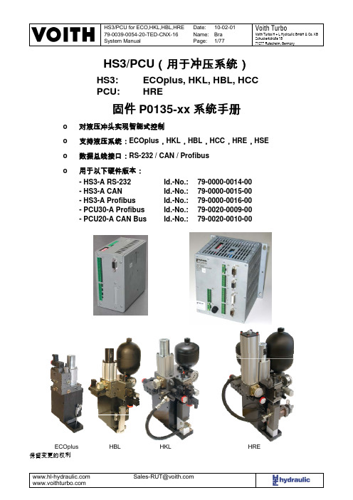
目录
1. 修改记录 .............................................................................................................................................. 5 2. 总说明.................................................................................................................................................. 5 3. 概要 ..................................................................................................................................................... 6
Id.-No.: Id.-No.: Id.-No.: Id.-No.: Id.-No.:
79-0000-0014-00 79-0000-0015-00 79-0000-0016-00 79-0020-0009-00 79-0020-0010-00
ECOplus 保留变更的权利
ECOplus, HKL, HBL, HCC HRE
固件 P0135-xx 系统手册
o 对液压冲头实现智能式控制
o 支持液压系统:ECOplus,HKL,HBL,HCC,HRE,HSE
o 数据总线接口:RS-232 / CAN / Profibus
o 用 HS3-A CAN - HS3-A Profibus - PCU30-A Profibus - PCU20-A CAN Bus
RexrothMTX简明调试手册
2.2.4 键盘------------------------------------------------------------------------------13 2.2.5 RECO Inline 模块-------------------------------------------------------------14 2.2.6 驱动器---------------------------------------------------------------------------17
修订时间 08 / 2007
前言
首先,欢迎您使用博世力士乐的产品,本手册主要面向机床及相似应用的 OEM 厂商所编制,里面主要介绍了 MTX 在应用方案中的常用配置、接线方式及一个简 单的工程实例,希望对您的设计有所帮助。如果您在设计初期,对安装尺寸有所 需求,可以直接参阅我们在附录中的硬件尺寸介绍。
2.2.2 工控机---------------------------------------------------------------------------7
2.2.3 操作面板------------------------------------------------------------------------10
3. PLC 主程序的编制-----------------------------------------------------------------------------40
5) 编译、下载及运行 PLC 程序--------------------------------------------------------40
六、螺距补偿----------------------------------------------------------------------------------------------56 七、数据的备份与恢复----------------------------------------------------------------------------------58
力士乐驱动器使用说明
力士乐驱动器参数调试说明本说明书针对非正弦用力士乐驱动器。
主要讲述驱动软件的使用、参数配置、PID调节等。
一、软件使用1.MLC04v16软件的安装安装文件夹内有CD1、CD2、CD3三个文件夹,打开CD1文件夹,⏹双击setup.exe进行安装,如图所示选择英文后,点Next⏹按如图所示选择,点Next。
⏹点击Next⏹点击Next⏹选择接受,后点击Next⏹输入名称,点击Next⏹选择安装目录,然后点击Next⏹点Install⏹安装进度如下:真个过程可能要10多分钟,看电脑性能。
⏹完成窗口如下:⏹完成后需要重启。
点”是”自动重启,点”否”则不重启。
2.软件操作⏹打开软件●双击桌面快捷方式,如下图所示。
●通过点击开始菜单->程序->Rexroth->IndraWorks7.14.166.0->Engineering.来打开。
⏹软件使用●工程的使用如下图点击Create an empty project为建立一个新工程。
点击Open project打开一个现有工程。
点击Scan for devices扫描串口总线上的设备点击Restore project把保存的已压缩工程,解压缩。
点击下面快捷按钮,第一个为新建工程,第二个位打开现有工程。
点击File下拉菜单后,New:新建工程;Open:打开工程。
与伺服启动器联机打开工程后变为点黄色图标进入虚拟模式。
点蓝色图标连接实际驱动器。
如果端口配置正常则直接联机,否则会弹出如下窗口。
点击Scan for Device后弹出如下窗口点Next后自动寻找设备。
未找到设备则弹出下面创库示波器功能点Diagnostics下拉菜单,点击Oscilloscope下图所示为示波器窗口。
采集时间配置:点击右上角的Configure后弹出,时间配置。
其中Memory depth,采集的点数Time period:每10ms采集一个点Recording time:前面两项相乘得出的总采样时间。
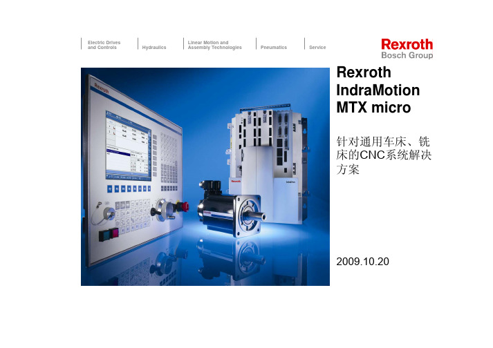
micro 演示资料(力士乐)
Electric Drives and ControlsHydraulicsLinear Motion and Assembly TechnologiesPneumaticsServiceRexroth IndraMotion MTX micro针对通用车床、铣 床的CNC系统解决 方案2009.10.201目录1. 引言 2. 系统概述 3. 硬件组成4-轴 NC-Drive HCQ 3-轴 NC-Drive HCT 伺服电机 主轴电机 操作面板 VDP80 附件 4. 软件功能 CNC PLC 驱动 标准循环 机械补偿 5. 用户界面 基本界面 刀具管理Electric Drives and Controls 4/2/2009, IndraMotion MTX micro - Launch Package © Bosch Rexroth AG 2009. All rights reserved, also regarding any disposal, exploitation, reproduction, editing, distribution, as well as in the event of applications for industrial property rights.4. 调试 简明安装调试文档 IW-Engineering IW-Drive 5. 目前使用情况2IndraMotion MTX micro+ 为通用数控机床定制的操作面板用于车床 (8,4“) 用于铣床(10.4‘‘)+ 一体化多轴伺服驱动与电源模块,32位处理器,数字输入和输出,百兆以太 网口的通讯+ 伺服和主轴电机均采用 高分辨率、绝对值编码器 = 中低档数控车, 钻和铣床的系统 解决方案Electric Drives and Controls 4/2/2009, IndraMotion MTX micro - Launch Package © Bosch Rexroth AG 2009. All rights reserved, also regarding any disposal, exploitation, reproduction, editing, distribution, as well as in the event of applications for industrial property rights.3IndraMotion MTX micro 系统组成 (2伺服轴 + 1主轴)DNC VDP80.1 8,4“ 真彩液晶显示器 HMIIndraWorks Engineering以太网 TCP/IPPLC I/OUSB存储卡 LVDS外接手轮(选项)系统IndraDrive HCT主轴编码器QSK 伺服电机CF 存储卡标准变频主轴电机Electric Drives and Controls 4/2/2009, IndraMotion MTX micro - Launch Package © Bosch Rexroth AG 2009. All rights reserved, also regarding any disposal, exploitation, reproduction, editing, distribution, as well as in the event of applications for industrial property rights.4IndraMotion MTX micro 系统组成 (3伺服轴 + 1主轴)DNC VDP80.1 10,4“ 真彩液晶显示器 HMIIndraWorks EngineeringUSB 存储卡以太网 TCP/IPPLC I/OLVDS外接手轮系统IndraDrive HCQ第二主轴编码器QSK伺服电机CF 存储卡MAD主轴电机Electric Drives and Controls 4/2/2009, IndraMotion MTX micro - Launch Package © Bosch Rexroth AG 2009. All rights reserved, also regarding any disposal, exploitation, reproduction, editing, distribution, as well as in the event of applications for industrial property rights.5IndraMotion MTX micro 系统 (2伺服轴 + 2主轴)DNC VDP80.1 8,4“ 真彩液晶显示器 HMIIndraWorks EngineeringUSB 存储卡以太网 TCP/IPPLC I/OLVDS手轮 (选项)系统IndraDrive HCQQSK伺服电机 第二主轴编码器MAD主轴电机CF 存储卡Electric Drives and Controls 4/2/2009, IndraMotion MTX micro - Launch Package © Bosch Rexroth AG 2009. All rights reserved, also regarding any disposal, exploitation, reproduction, editing, distribution, as well as in the event of applications for industrial property rights.6IndraMotion MTX micro IndraDrive HCT 和 HCQ内置多轴驱动模块电源模块 3-轴的IndraDrive HCT (20kW) -或4-轴的IndraDrive HCQ (25kW) 回馈能量释放器用于连接外部制动电阻 可外接编码器 (TTL, 1Vpp, Endat…) CNC 处理器 PLC 处理器 数字输入和输出 (24V) 以太网通讯 USB 接口 CF卡用于存储所有机床数据Electric Drives and Controls 4/2/2009, IndraMotion MTX micro - Launch Package © Bosch Rexroth AG 2009. All rights reserved, also regarding any disposal, exploitation, reproduction, editing, distribution, as well as in the event of applications for industrial property rights.7IndraMotion MTX micro IndraDrive HCT 和 HCQHCQ02.1E-W0025 HCT02.1E-W0020轴 (包括. 主轴) 主轴432 5 11kW 5kW/3,5kW/3,5kW 17Nm/12Nm/12Nm 25kW1 4多相编码器接口 主轴最大额定功率 伺服轴额定功率 伺服轴最大扭矩3,5kW/3,5kW 12Nm/12Nm 20kW轴模块额定功率 电源电压和频率 直接连接至电网200..500V, 50..60Hz 是,非再生反馈Electric Drives and Controls 4/2/2009, IndraMotion MTX micro - Launch Package © Bosch Rexroth AG 2009. All rights reserved, also regarding any disposal, exploitation, reproduction, editing, distribution, as well as in the event of applications for industrial property rights.8IndraMotion MTX micro IndraDrive HCT 和 HCQHCQ02.1E-W0025 HCT02.1E-W0020CNC 处理器 RAM 内存 CF 存储卡 IPO 循环周期 CNC 通道 进给轴 主轴-C轴 USB 接口32 bit / 500 MHz / Intel兼容 512 MByte 128 MByte4 ms2 4 2 是 3 1以太网通讯接口高速Electric Drives and Controls 4/2/2009, IndraMotion MTX micro - Launch Package © Bosch Rexroth AG 2009. All rights reserved, also regarding any disposal, exploitation, reproduction, editing, distribution, as well as in the event of applications for industrial property rights.9IndraMotion MTX micro IndraDrive HCT 和 HCQHCQ02.1E-W0025 HCT02.1E-W0020PLC 进程 (循环) PLC 循环时间 (典型) PLC 每条语句时间 (1000 instr.) 内置数字输入和输出 数字输入和输出 (选项) 最大输出电流 数字HMI 输入 / 输出 编程 IEC61131 通过HMI 编程2 进程, 1024 句程序 10 ms 30 us32 I / 16 O 24V DC2 x (32 I / 16 O) 24V DC 500 mA 256 I / 128 O IL,LD,FUP,ST,SFC 准备中Electric Drives and Controls 4/2/2009, IndraMotion MTX micro - Launch Package © Bosch Rexroth AG 2009. All rights reserved, also regarding any disposal, exploitation, reproduction, editing, distribution, as well as in the event of applications for industrial property rights.10号轴接口(HCTElectric Drives and Controls 4/2/2009, IndraMotion MTX micro -Launch PackageBosch Rexroth AG 2009. All rights reserved, also regarding any disposal, exploitation, reproduction, editing, distribution, as well as in the event of applications for industrial property12Electric Drives and Controls 4/2/2009, IndraMotion MTX micro -Launch Package©Bosch Rexroth AG 2009. All rights reserved, also regarding any disposal, exploitation, reproduction, editing, distribution, as well as in the event of applications for industrial property rights.IndraMotion MTX micro IndraDrive HCT 和HCQ超强的性价比一体化的多轴模块 直接连接电源无需变压器 系统结构简洁可直接连接24V 信号500mA 输出电流可节省继电器 简单的配线系统所有的接线板都在正面集成电缆卡口集成的屏蔽连接11kW 主轴, 17/12/12Nm 伺服,64点输入, 32点输出13Electric Drives and Controls 4/2/2009, IndraMotion MTX micro -Launch Package©Bosch Rexroth AG 2009. All rights reserved, also regarding any disposal, exploitation, reproduction, editing, distribution, as well as in the event of applications for industrial property rights.IndraMotion MTX micro IndraDyn伺服电机伺服电机可用的伺服电机: QSK061 和QSK075 扭矩范围从3.5 至17Nm 最高转速3000 min-1编码器: 多圈绝对值,分辨率: 128x213 电子铭牌 调试简单可转动的电缆接头高可靠性,历经上万次试验15Electric Drives and Controls 4/2/2009, IndraMotion MTX micro -Launch Package©Bosch Rexroth AG 2009. All rights reserved, also regarding any disposal, exploitation, reproduction, editing, distribution, as well as in the event of applications for industrial property rights.IndraMotion MTX micro IndraDyn 伺服电机自带内存的多圈编码器带来的优势无需极限开关在断电时仍保留轴绝对位置信息-无需电池无需轴回零电子铭牌使电机的调试变得简单QSK 编码器M5技术数据光学编码器, HIPERFACE© 角度偏差:±80 角秒128 x 213= 1.048.576 个信息/ 电机每转 绝对值编码器范围为±2048转-10mm 节距, 齿轮比:i=0.5=±2048*10mm*0.5=±10.240mm 绝对值编码器行程范围Bosch Rexroth AG 2009. All rights reserved, also regarding any disposal, exploitation, reproduction, editing, distribution, as well as in the event of applications for industrial property功能强大的异步主轴电机高扭矩宽功率范围最高转速9000min-1单圈编码器,分辨率: 2048x213编码器数据不易丢失无需电池标准参数可使用接线盒IP65 防护等级包括风扇高可靠性,历经上万次试验Bosch Rexroth AG 2009. All rights reserved, also regarding any disposal, exploitation, reproduction, editing, distribution, as well as in the event of applications for industrial property20Electric Drives and Controls 4/2/2009, IndraMotion MTX micro -Launch Package©Bosch Rexroth AG 2009. All rights reserved, also regarding any disposal, exploitation, reproduction, editing, distribution, as well as in the event of applications for industrial property rights.IndraMotion MTX micro IndraView VDP80.1HMI 面板集成以下功能:高亮度8,4“或10,4“彩色TFT 显示屏 ASCII 键盘用于参数设定和NC 程序修改 进给及主轴倍率开关 集成手轮(车床版) 可连接外部手轮PLC 输入和指示灯显示 循环启动/进给保持按键 急停按键(双通道)USB接口用于数据传输和备份IndraMotion MTX micro IndraView VDP80.1车床版 VDP80.1FAN 屏幕大小 (彩色 TFT) 显示分辨率 8,4” 640x480px 24V DC±20%, 36W 铣床版 VDP80.1FBN 10,4”供电 防护等级 (已安装的) 尺寸 (LxWxH) 手轮IP54 420x327x80mm 1 x 内部, 1 x 外部 进给 1 x 外部 进给,主轴倍率开关 MOP 键 (PLC 输入和指示灯) K 键 (为OEM提供)34 638 10Electric Drives and Controls 4/2/2009, IndraMotion MTX micro - Launch Package © Bosch Rexroth AG 2009. All rights reserved, also regarding any disposal, exploitation, reproduction, editing, distribution, as well as in the event of applications for industrial property rights.21IndraMotion MTX micro IndraView VDP80.1FAN – 车床版 HMIVDP80.1FAN-..Electric Drives and Controls 4/2/2009, IndraMotion MTX micro - Launch Package © Bosch Rexroth AG 2009. All rights reserved, also regarding any disposal, exploitation, reproduction, editing, distribution, as well as in the event of applications for industrial property rights.22IndraMotion MTX micro IndraView VDP80.1FBN – 铣床版 HMIVDP80.1FBN-..Electric Drives and Controls 4/2/2009, IndraMotion MTX micro - Launch Package © Bosch Rexroth AG 2009. All rights reserved, also regarding any disposal, exploitation, reproduction, editing, distribution, as well as in the event of applications for industrial property rights.23IndraMotion MTX micro IndraView VCH 手轮手轮VCH急停开关 轴运动有效开关双通道 NC 单通道 NO 100 脉冲/转 可选手轮 电缆长度 轴选择 倍率开关X,Y,Z,4 1,10,100 (x0.001mm)Electric Drives and Controls 4/2/2009, IndraMotion MTX micro - Launch Package © Bosch Rexroth AG 2009. All rights reserved, also regarding any disposal, exploitation, reproduction, editing, distribution, as well as in the event of applications for industrial property rights.24IndraMotion MTX micro CNC 功能车削 – 精确和完整刚性攻丝 主轴刀塔复合轴 柱面和端面的车铣加工 C轴功能和动力刀具功能铣削 – 高速和高效语句预读功能 缩放和镜像 倒角功能 轴相关的急进限制,扭矩限制其它功能 …移动及倾斜工件坐标系统 CPL高级语言提供广泛的功能扩展 多种机械补偿Electric Drives and Controls 4/2/2009, IndraMotion MTX micro - Launch Package © Bosch Rexroth AG 2009. All rights reserved, also regarding any disposal, exploitation, reproduction, editing, distribution, as well as in the event of applications for industrial property rights.25IndraMotion MTX micro CNC 功能车削 – 精确和完整集成的加工循环:车,钻,铣 刚性攻丝 主轴刀塔复合轴 C轴功能 柱面和端面的车铣加工 缩放和镜像 刀具补偿 刀具定向补偿 主轴可外接编码器 自动选择档位 自动选择电机绕组Electric Drives and Controls 4/2/2009, IndraMotion MTX micro - Launch Package © Bosch Rexroth AG 2009. All rights reserved, also regarding any disposal, exploitation, reproduction, editing, distribution, as well as in the event of applications for industrial property rights.26IndraMotion MTX micro CNC 功能铣削 – 高效和高速预读功能 缩放和镜像 倒角功能 倒圆角 立铣刀半径补偿 纳米插补 在加工区域内移动及倾斜工件坐标系统 扭矩限制 转台使用Hirth轴或roll-over轴Electric Drives and Controls 4/2/2009, IndraMotion MTX micro - Launch Package © Bosch Rexroth AG 2009. All rights reserved, also regarding any disposal, exploitation, reproduction, editing, distribution, as well as in the event of applications for industrial property rights.27IndraMotion MTX micro CNC 功能其它功能 …CPL高级语言提供广泛的功能扩展 可编程加速度 刀具的几何和磨损补偿 最多管理999把刀 螺距误差补偿 交叉补偿 (交叉轴) 程序与IndraMotion MTX产品家族相兼容Electric Drives and Controls 4/2/2009, IndraMotion MTX micro - Launch Package © Bosch Rexroth AG 2009. All rights reserved, also regarding any disposal, exploitation, reproduction, editing, distribution, as well as in the event of applications for industrial property rights.28IndraMotion MTX micro CNC 功能丝杆螺距误差补偿(LSEC) 可实现螺距的双向补偿 MTX micro系统使用双向丝杆螺距补偿,补偿方法简单, 12000个补偿点,最大 限度保证机床精度直接使用内置NC程序编辑器输入测量的数据,简单(lsecc01.tab – 轴1补偿文件) 20000.0 10000.0 (start at 20mm, 10mm increment) 2.0 -6.0 (20mm) 2.0 -4.0 (30mm) 4.0 2.0 (40mm) 6.0 2.0 (50mm) 2.0 6.0 (60mm) -4.0 0.0 (70mm) -4.0 -6.0 (80mm)Electric Drives and Controls 4/2/2009, IndraMotion MTX micro - Launch Package © Bosch Rexroth AG 2009. All rights reserved, also regarding any disposal, exploitation, reproduction, editing, distribution, as well as in the event of applications for industrial property rights.29IndraMotion MTX micro CNC 功能交叉补偿 (CCOMP) 依据其它轴的位置信息进行轴错误补偿 双向误差补偿 最高至12.000补偿点, 用户自定义距离(0.1µm 步) 直接使用内置NC程序编辑器输入测量的数据,简单(cnc03r02.tab – CCOMP file axis 3 > axis 2) 20000.0 100000.0 (start at 20mm, 100mm increment) 0.0 0.0 (20mm) 4.0 3.0 (120mm) 6.0 6.0 (220mm) 6.5 6.5 (320mm) 6.0 6.0 (420mm) 4.0 3.0 (520mm) 0.0 0.0 (620mm)Electric Drives and Controls 4/2/2009, IndraMotion MTX micro - Launch Package © Bosch Rexroth AG 2009. All rights reserved, also regarding any disposal, exploitation, reproduction, editing, distribution, as well as in the event of applications for industrial property rights.30IndraMotion MTX micro CNC零件编程标准G代码编程遵循 DIN ISO 66025 / RS274 集成CNC编辑器用于程序编辑 内置可用于车,钻和铣的标准加工循环 – 例如 …钻孔, 镗孔, 多点钻 钻孔, 镗孔, 多点钻 绞孔 绞孔 攻丝 攻丝 矩阵分布或圆周分布钻加工 矩阵分布或圆周分布钻加工 轮廓车削循环和精车削循环 轮廓车削循环和精车削循环 凹槽加工及表面凹进 凹槽加工及表面凹进 根据切削次数自动计算切削量 根据切削次数自动计算切削量标准G-代码轮廓编程直接输入图纸数据 轮廓元素可以用G代码简单快速地描述图纸CNC程序工件Electric Drives and Controls 4/2/2009, IndraMotion MTX micro - Launch Package © Bosch Rexroth AG 2009. All rights reserved, also regarding any disposal, exploitation, reproduction, editing, distribution, as well as in the event of applications for industrial property rights.31IndraMotion MTX micro CNC零件编程 从图纸到最终工件直接输入图纸数据至NC零件程序 轮廓元素可以用G代码简单快速地描述 使用内置的车/铣循环进行轮廓加工 在CNC程序中定义轮廓 -或在子程序中定义轮廓 使用专门的固定循环定义和加工常用轮廓元素 螺纹 凹槽 表面凹进 型腔 轮廓的定义可包含轮廓元素Electric Drives and Controls 4/2/2009, IndraMotion MTX micro - Launch Package © Bosch Rexroth AG 2009. All rights reserved, also regarding any disposal, exploitation, reproduction, editing, distribution, as well as in the event of applications for industrial property rights.32IndraMotion MTX micro CNC零件编程从图纸到最终工件 – 车削举例N110 G1 X0 Z0 // A N120 G1(CHL1) X14 N130 G1 Z-15 N140 G1(CHL2) X28 N150 G1(RND2) Z-40 N160 G1(CHL1) X38 N170 G1 Z-50 // BN10 G0 G18 G54 G90 DIA N20 T1 M6 N30 G95 G96 S200M3 F.25 N40 X45 Z5 // 粗加工 N50 G171(S110,E170,CD2,LD1,CR.3,CA.3) N60 T2 M6 N70 G95 G96 S200M3 F.15 N80 X15 Z5 // 精加工 N90 G170(S110,E170)Electric Drives and Controls 4/2/2009, IndraMotion MTX micro - Launch Package © Bosch Rexroth AG 2009. All rights reserved, also regarding any disposal, exploitation, reproduction, editing, distribution, as well as in the event of applications for industrial property rights.33IndraMotion MTX micro CNC零件编程从图纸到最终工件 – 车削举例N10 G0 G18 G54 G90 DIA N20 T3 M6 N30 G95 G96 S200M3 F.125 N40 X30 Z-20 // 表面开槽 N50 G191(ORI8,SR28,SA-25,W5,DT4,TW2) N10 G0 G18 G54 G90 DIA N20 T2 M6 N30 G95 G96 S200M3 F.25 N40 X18 Z-10 // 用户自定义表面凹槽 N50 G176(ORI3,DN14,DG12,SA-15,WL5,R1,ANG30)N10 G0 G18 G54 G90 DIA N20 T4 M6 N30 G95 G97 S200M3 N40 X18 Z5 // 车螺纹 N50 G167(SR14,SA3,EA-10,TP1,DT-.541,FD.3)Electric Drives and Controls 4/2/2009, IndraMotion MTX micro - Launch Package © Bosch Rexroth AG 2009. All rights reserved, also regarding any disposal, exploitation, reproduction, editing, distribution, as well as in the event of applications for industrial property rights.34IndraMotion MTX micro CNC 用户界面系统主界面主屏幕的显示界面依赖于操作选择键 (自动, 手动, MDI) 可从主屏幕编辑加工程序Electric Drives and Controls 4/2/2009, IndraMotion MTX micro - Launch Package © Bosch Rexroth AG 2009. All rights reserved, also regarding any disposal, exploitation, reproduction, editing, distribution, as well as in the event of applications for industrial property rights.35IndraMotion MTX micro CNC 用户界面界面通道状态及选 择的操作模式 当前诊断信息选择的通道和 用户登陆状态 轴位置和轴状 态选择的零件程 序选择子操作模 式清晰的软键实 现简易的操作进给倍率和主 轴倍率显示Electric Drives and Controls 4/2/2009, IndraMotion MTX micro - Launch Package © Bosch Rexroth AG 2009. All rights reserved, also regarding any disposal, exploitation, reproduction, editing, distribution, as well as in the event of applications for industrial property rights.36IndraMotion MTX micro CNC 用户界面刀具管理 所有的刀具数据和补偿在同一列表 可在刀具表中直接编辑数据刀套可用M键来实现 PB,TL等的切换T4刀的全部数据 都可以在一行内 找到Electric Drives and Controls 4/2/2009, IndraMotion MTX micro - Launch Package © Bosch Rexroth AG 2009. All rights reserved, also regarding any disposal, exploitation, reproduction, editing, distribution, as well as in the event of applications for industrial property rights.37IndraMotion MTX micro CNC用户界面刀具管理界面 刀具的数据管理和刀具的偏置信息刀具数据每个刀刃 • 几何偏置 • 刀具定向 • 磨损偏置 刀具管理刀具寿命Electric Drives and Controls 4/2/2009, IndraMotion MTX micro - Launch Package © Bosch Rexroth AG 2009. All rights reserved, also regarding any disposal, exploitation, reproduction, editing, distribution, as well as in the event of applications for industrial property rights.38IndraMotion MTX micro CNC用户界面程序管理 操作风格与Windows类似。
Rexroth 标准型力量单元说明说明书
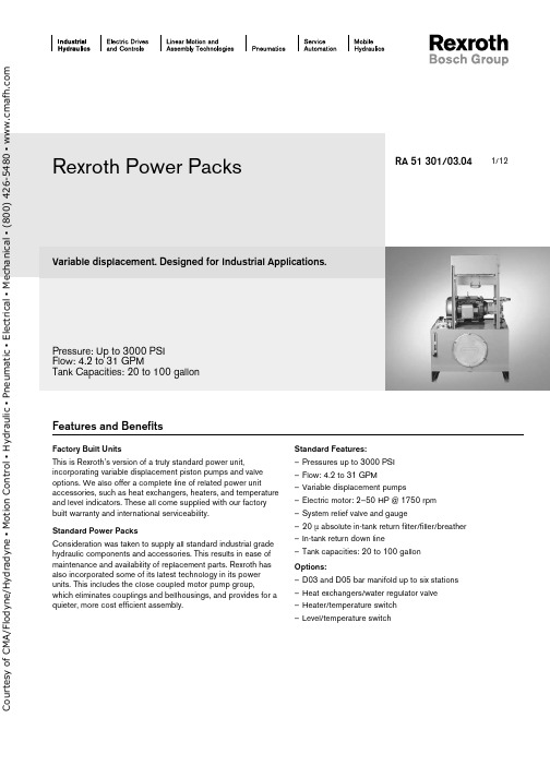
1/12Variable displacement. Designed for Industrial Applications.Pressure: Up to 3000 PSI Flow: 4.2 to 31 GPMTank Capacities: 20 to 100 gallonRA 51 301/03.04Factory Built UnitsThis is Rexroth’s version of a truly standard power unit,incorporating variable displacement piston pumps and valve options. We also offer a complete line of related power unitaccessories, such as heat exchangers, heaters, and temperature and level indicators. These all come supplied with our factory built warranty and international serviceability.Standard Power PacksConsideration was taken to supply all standard industrial grade hydraulic components and accessories. This results in ease of maintenance and availability of replacement parts. Rexroth has also incorporated some of its latest technology in its power units. This includes the close coupled motor pump group,which eliminates couplings and bellhousings, and provides for a quieter, more cost efficient assembly.Standard Features:– Pressures up to 3000 PSI – Flow: 4.2 to 31 GPM – Variable displacement pumps – Electric motor: 2–50 HP @ 1750 rpm – System relief valve and gauge– 20 µ absolute in-tank return filter/filler/breather – In-tank return down line– Tank capacities: 20 to 100 gallon Options:– D03 and D05 bar manifold up to six stations – Heat exchangers/water regulator valve – Heater/temperature switch – Level/temperature switchRexroth Power PacksFeatures and Benefitso u r t e s y o f C M A /F l o d y n e /H y d r a d y n e ▪ M o t i o n C o n t r o l ▪ H y d r a u l i c ▪ P n e u m a t i c ▪ E l e c t r i c a l ▪ M e c h a n i c a l ▪ (800) 426-5480 ▪ w w w .c m a f h .c o m2/12 Bosch Rexroth Corp. | Industrial Hydraulics Variable Displacement Power Packs | RA 51 301/03.04Model codePPV*Power Pack Variable Reservoir Size= 20= 40= 60= 100Pump SizeA10VSO 10 DR A10VSO 10 DFR A10VSO 18 DR A10VSO 18 DFR AA10VSO 28 DR AA10VSO 28 DFR AA10VSO 45 DR AA10VSO 45 DFR A10VO 71 DR A10VO 71 DFR(20 Gallon)(20 Gallon)(20 Gallon)(20 Gallon)(40 Gallon)(40 Gallon)(60 Gallon)(60 Gallon)(100 Gallon)(100 Gallon)= A = B = 1= 2= 3= 4= 5= 6= 7= 8Motor HorsepowerSee basic unit table for horsepower (hp based on reservoir & pump size)Valve OptionsRelief Valve and GaugeD03 Parallel Bar Manifold, one thru six stations w/ pressure gauge and relief D05 Parallel Bar Manifold, one thru six stations w/ pressure gauge and relief= RV= 3BMR1–6= 5BMR1–6Specify Flow & PressureLevel/Temp. Switch Options0 = None LT = Level/Temp. Switch0 =2 =3 =Heater OptionsNoneElectric Heater, 3 phase with Temperature Switch Electric Heater, single phasewith Temperature Switch 0 =1 =2 =3 =4 =Heat Exchanger OptionsNoneAir/Oil, Leakage Line Water/Oil, Leakage Line Water/Oil, Return LineAir/Oil, 3-phase Motor, Return Linewith Temperature Switch1 =2 =Pressure Gauge Option0–3000 PSI 0–5000 PSIExample: PPV403103BMR1120LT - 10 GPM / 1000 PSICircuits (see page 10 for Connection Sizes)Relief Valve Option (RV)Bar Manifold (BMR) Option with D03 or D05,with Relief Valveo u r t e s y o f C M A /F l o d y n e /H y d r a d y n e ▪ M o t i o n C o n t r o l ▪ H y d r a u l i c ▪ P n e u m a t i c ▪ E l e c t r i c a l ▪ M e c h a n i c a l ▪ (800) 426-5480 ▪ w w w .c m a f h .c o m20 Gallon Steel Reservoir: dimensions in inches (millimeters)Model CodePump Model Motor Frame Power*hp (kw)Displacement in 3/rev (cm 3/rev)Max. Flow GPM (L/min)Max. PressurePSI (bar)PPV20/ /2A10VSO10145 2.0 (1.4)0.64 (10) 4.2 (16)3000 (200)PPV20/ /3A10VSO10182 3.0 (2.2)0.64 (10) 4.2 (16)3000 (200)PPV20/ /5A10VSO10 184 5.0 (3.7)0.64 (10) 4.2 (16)3000 (200)PPV20/ /7.5A10VSO102137.5 (5.5)0.64 (10) 4.2 (16)3000 (200)PPV20/ /10A10VSO1021510.0 (7.4)0.64 (10) 4.2 (16)3000 (200)PPV20/ /2A10VSO18145 2.0 (1.4) 1.10 (18)8.0 (30)3000 (200)PPV20/ /3A10VSO18182 3.0 (2.2) 1.10 (18)8.0 (30)3000 (200)PPV20/ /5A10VSO18184 5.0 (3.7) 1.10 (18)8.0 (30)3000 (200)PPV20/ /7.5A10VSO182137.5 (5.5) 1.10 (18)8.0 (30)3000 (200)PPV20/ /10A10VSO1821510.0 (7.4)1.10 (18)8.0 (30)3000 (200)Note: Flows and pressures are factory set according to customer specifications * – Motors are closed-coupled, 3 phase, 1750, 230/460 volt, 1.15 S.F.AB A B A B AB 121212121212RA 51 301/03.04 | Variable Displacement Power Packs Industrial Hydraulics | Bosch Rexreoth Corp. 3/12o u r t e s y o f C M A /F l o d y n e /H y d r a d y n e ▪ M o t i o n C o n t r o l ▪ H y d r a u l i c ▪ P n e u m a t i c ▪ E l e c t r i c a l ▪ M e c h a n i c a l ▪ (800) 426-5480 ▪ w w w .c m a f h .c o m40 Gallon Steel Reservoir: dimensions in inches (millimeters)Model CodePump Model MotorFrame Power*hp (kw)Displacement in 3/rev (cm 3/rev)Max. Flow GPM (L/min)Max. Pressure PSI (bar)PPV40/ /5AA10VSO28 213 5.0 (3.7) 1.7 (28)12.0 (45)3000 (200)PPV40/ /7.5AA10VSO282137.5 (5.5) 1.7 (28)12.0 (45)3000 (200)PPV40/ /10AA10VSO2821510.0 (7.4) 1.7 (28)12.0 (45)3000 (200)PPV40/ /15AA10VSO2825415.0 (11.1) 1.7 (28)12.0 (45)3000 (200)PPV40/ /20AA10VSO2825620.0 (14.9) 1.7 (28)12.0 (45)3000 (200)PPV40/ /25A10VO2828425.0 (18.6)1.7 (28)12.0 (45)3000 (200)34Note: Flows and pressures are factory set according to customer specifications * – Motors are closed-coupled, 3 phase, 1750, 230/460 volt, 1.15 S.F.34343434344/12 Bosch Rexroth Corp. | Industrial Hydraulics Variable Displacement Power Packs | RA 51 301/03.04o u r t e s y o f C M A /F l o d y n e /H y d r a d y n e ▪ M o t i o n C o n t r o l ▪ H y d r a u l i c ▪ P n e u m a t i c ▪ E l e c t r i c a l ▪ M e c h a n i c a l ▪ (800) 426-5480 ▪ w w w .c m a f h .c o m60 Gallon Steel Reservoir: dimensions in inches (millimeters)Model CodePump Model MotorFrame Power*hp (kw)Displacement in 3/rev (cm 3/rev)Max. Flow GPM (L/min)Max. Pressure PSI (bar)PPV60/ /7.5AA10VSO45 2137.5 (5.5) 2.7 (45)19.5 (74)3000 (200)PPV60/ /10AA10VSO4521310.0 (7.4) 2.7 (45)19.5 (74)3000 (200)PPV60/ /15AA10VSO4525415.0 (11.1) 2.7 (45)19.5 (74)3000 (200)PPV60/ /20AA10VSO4525620.0 (14.9) 2.7 (45)19.5 (74)3000 (200)PPV60/ /25A10VO4528425.0 (18.6) 2.7 (45)19.5 (74)3000 (200)PPV60/ /30A10VO4528630.0 (22.4)2.7 (45)19.5 (74)3000 (200)565656565656Note: Flows and pressures are factory set according to customer specifications * – Motors are closed-coupled, 3 phase, 1750, 230/460 volt, 1.15 S.F.RA 51 301/03.04 | Variable Displacement Power Packs Industrial Hydraulics | Bosch Rexreoth Corp. 5/12o u r t e s y o f C M A /F l o d y n e /H y d r a d y n e ▪ M o t i o n C o n t r o l ▪ H y d r a u l i c ▪ P n e u m a t i c ▪ E l e c t r i c a l ▪ M e c h a n i c a l ▪ (800) 426-5480 ▪ w w w .c m a f h .c o m100 Gallon Steel Reservoir: dimensions in inches (millimeters)Model CodePump Model MotorFrame Power*hp (kw)Displacement in 3/rev (cm 3/rev)Max. Flow GPM (L/min)Max. Pressure PSI (bar)PPV100/ /25A10VO7128425.0 (11.1) 4.3 (71)31.0 (117)3000 (200)PPV100/ /30A10VO7128630.0 (14.9) 4.3 (71)31.0 (117)3000 (200)PPV100/ /40A10VO7132440.0 (18.6) 4.3 (71)31.0 (117)3000 (200)PPV100/ /50A10VO7132650.0 (22.4)4.3 (71)31.0 (117)3000 (200)78Note: Flows and pressures are factory set according to customer specifications * – Motors are closed-coupled, 3 phase, 1750, 230/460 volt, 1.15 S.F.7878786/12 Bosch Rexroth Corp. | Industrial Hydraulics Variable Displacement Power Packs | RA 51 301/03.04o u r t e s y o f C M A /F l o d y n e /H y d r a d y n e ▪ M o t i o n C o n t r o l ▪ H y d r a u l i c ▪ P n e u m a t i c ▪ E l e c t r i c a l ▪ M e c h a n i c a l ▪ (800) 426-5480 ▪ w w w .c m a f h .c o mPower Pack Accessory ListOption20 Gallon 40 Gallon 60 Gallon 100 Gallon 1R978808140 = Exchanger R978808140 = Exchanger R978808140 = Exchanger R978808140 = Exchanger 2R978808105 = H20 Valve R978884023 = Exchanger R978808105 = H20 Valve R978884023 = Exchanger R978808105 = H20 Valve R978884023 = Exchanger R978808105 = H20 Valve R978888744 = Exchanger 3R978808105 = H20 Valve R978888727 = Exchanger R978808106 = H20 Valve R978888738 = Exchanger R978808106 = H20 Valve R978888738 = Exchanger R978808107 = H20 Valve R978888744 = Exchanger 4R978881427 = Temp. Switch R978907474 = Exchanger R978881427 = Temp. Switch R978907475 = Exchanger R978881427 = Temp. Switch R978907476 = Exchanger R978881427 = Temp. Switch R978907477 = Exchanger 2R978881427 = Temp. Switch R978805726 = Heater 3PH, 1 kw, 480 Volt R978881427 = Temp. Switch R978805726 = Heater 3PH, 1 kw, 480 Volt R978881427 = Temp. Switch R978805727 = Heater 3PH, 2 kw, 480 Volt R978881427 = Temp. Switch R978805728 = Heater 3PH, 3 kw, 480 Volt 3R978881427 = Temp. Switch R978802712 = Heater Single PH, 1 kw, 120 VoltR978881427 = Temp. Switch R978802712 = Heater Single PH, 1 kw, 120 VoltR978881427 = Temp. Switch R978802714 = Heater Single PH, 1 kw, 120 VoltR978881427 = Temp. Switch R978802716 = Heater Single PH, 1 kw, 120 Volt**LTR978903431R978903431R978903432R978903432E l e c t r i c H e a t e r s T e m p e r a t u r eS w i t c hH e a t E x c h a n g e r s / W a t e r R e g u l a t o r V a l v e / T e m p . S w i t c h** Temperature Switch, fixed setting at 135°F, Level Switch, non-adjustable, set at low level alarm.Heat Exchanger – Option 1 (R978808140)15105H e a t D i s s i p a t i o n (h p )O i l P r e s s u r e D r o p (p s i )Oil Flow (gpm)Material: Aluminum, Cabinet SteelRA 51 301/03.04 | Variable Displacement Power Packs Industrial Hydraulics | Bosch Rexreoth Corp. 7/12o u r t e s y o f C M A /F l o d y n e /H y d r a d y n e ▪ M o t i o n C o n t r o l ▪ H y d r a u l i c ▪ P n e u m a t i c ▪ E l e c t r i c a l ▪ M e c h a n i c a l ▪ (800) 426-5480 ▪ w w w .c m a f h .c o m8/12 Bosch Rexroth Corp. | Industrial Hydraulics Variable Displacement Power Packs | RA 51 301/03.04Heat Exchanger – Options 2 and 3H e a t D i s s i pat i o n (h p )Oil Flow (gpm)9876One PassTwo Pass❶ – Hot oil in ❸ – Cooling water in ❷ – Cool oil out ❹ – Cooling water outCommon dimensions: dimensions in inches (millimeters)Rexroth Part Number A B C D E F H SAER978884023 3.85 (98)8.19 (208)10.44 (262) 2.5 (64) 2.28 (57) 1.62 (41)#12 1 1/16 - 12 UN-2B R9788887277.85 (199)12.19 (310)14.14 (363) 2.5 (64) 2.28 (57) 1.62 (41)#12 1 1/16 - 12 UN-2B R978888738 3.00 (76)8.19 (208)10.71 (272) 3.0 (76) 2.84 (72) 2.59 (66)#24 1 7/8 - 12 UN-2B R978888744 6.18 (157)12.02 (305)15.45 (392)4.0 (102)3.12 (79)4.0 (102)#32 2 1/2 - 12 UN-2BRexroth Part Number JK Dia.L M NPT N P Q NPT R9788840230.34 (9) x 0.62 (16) 2.55 (65)10.38 (263)0.75N/A 3.26 (82) 2 (1/4”)R9788887270.34 (9) x 0.62 (16) 2.55 (65)14.38 (365)0.75N/A 3.26 (82) 2 (1/4”)R9788887380.44 (11) x 0.75 (19) 3.52 (89)9.69 (246) 1.00 1.62 (41) 3.46 (87)1/4”R9788887440.44 (11) x 1.00 (25)5.05 (128)14.33 (363)1.502.38 (60)4.45 (113)1/4”o u r t e s y o f C M A /F l o d y n e /H y d r a d y n e ▪ M o t i o n C o n t r o l ▪ H y d r a u l i c ▪ P n e u m a t i c ▪ E l e c t r i c a l ▪ M e c h a n i c a l ▪ (800) 426-5480 ▪ w w w .c m a f h .c o mRA 51 301/03.04 | Variable Displacement Power Packs Industrial Hydraulics | Bosch Rexreoth Corp. 9/12Water Regulating ValveCopper Bulb 11/16 Dia.Relief Valve Option – RVSize (NPT)Rexroth Part Number A B C 3/4”R978808105 3.567.66 3.801”R978808106 4.8410.70 4.721-1/4”R9788081074.8611.084.91Max. Water Flow:SizeGPM 3/4”401”551-1/4”75Temperature:Size Range Opening Pt.3/4” – 1-1/4”75° – 135°FPart No.P1P2T1,T2G1, G2A B C D Relief ValveSize R978904345Relief Block 3/4”Code 61–12 SAE (1-1/16-12)–8 SAE (3/4-16)–4 SAE (7/16-20) 4.50(115) 2.25(57) 3.00(76) 2.68(68)DBD10R900424149R978904347Relief Block1”Code 61–16 SAE (1-5/16-12)–12 SAE (1-1/16-16)–4 SAE (7/16-20)4.50(115)2.25(57)3.00(76)2.68(68)DBD10R900424149o u r t e s y o f C M A /F l o d y n e /H y d r a d y n e ▪ M o t i o n C o n t r o l ▪ H y d r a u l i c ▪ P n e u m a t i c ▪ E l e c t r i c a l ▪ M e c h a n i c a l ▪ (800) 426-5480 ▪ w w w .c m a f h .c o m10/12 Bosch Rexroth Corp. | Industrial Hydraulics Variable Displacement Power Packs | RA 51 301/03.044.00(102)5.00(127)3.27(83)5.00(127)5BMR16.88(175)5BMR210.13(257)5BMR313.38(340)5BMR416.62(422)5BMR519.87(505)5BMR611.61(295)9.78(248)3.50(89) 3.00(76) 3.27(83)3.75(95)3BMR14.25(121)3BMR2 6.50(165)3BMR38.50(216)3BMR410.63(270)3BMR512.76(324)3BMR62.83(72)9.03(229)6.19(157)Bar Manifold Options: dimensions in inches (millimeters)3BMR5BMRo u r t e s y o f C M A /F l o d y n e /H y d r a d y n e ▪ M o t i o n C o n t r o l ▪ H y d r a u l i c ▪ P n e u m a t i c ▪ E l e c t r i c a l ▪ M e c h a n i c a l ▪ (800) 426-5480 ▪ w w w .c m a f h .c o mRA 51 301/03.04 | Variable Displacement Power Packs Industrial Hydraulics | Bosch Rexreoth Corp. 11/12In-Tank Return Line Filter Replacement CartridgePPV 20= P/N R978008660PPV 40, 60, & 100 = P/N R978008659Customer Connection Port SizesRV Option (Relief Valve w/GaugePPV 20 P = 1-1/16-12 (SAE-12)T = 1-1/16-12 (SAE-12) D = 3/4-16 (SAE-8)PPV 40 P = 1-1/16-12 (SAE-12) T = 1-5/16-12 (SAE 16) D = 1-1/16-12 (SAE-12)PPV 60 P = 1-5/16-12 (SAE-16) T = 1-5/16-12 (SAE-16) D = 1-1/16-12 (SAE-12)PPV 100 P = 1-5/16-12 (SAE-16) T = 1-7/8-12 (SAE 24)D = 1-5/16-16 (SAE-16)3BMR & 5BMR Options(D03 or D05 Parallel Bar Manifold w/Relief Valve & Gauge)3BMR1–6 X1 - X12 = 3/4-16 (SAE-8)5BMR1–6X1 - X12 = 1-1/16-12 (SAE-12)C o u r t e s y o f C M A /F l o d y n e /H y d r a d y n e ▪ M o t i o n C o n t r o l ▪ H y d r a u l i c ▪ P n e u m a t i c ▪ E l e c t r i c a l ▪ M e c h a n i c a l ▪ (800) 426-5480 ▪ w w w .c m a f h .c o mBosch Rexroth Corp.Industrial Hydraulics 2315 City Line RoadBethlehem, PA 18017-2131USATelephone (610) 684-8300Facsimile (610) © 2004 Bosch Rexroth CorporationAll rights reserved. Neither this document nor any part of it may be reproduced, duplicated circulated or disseminated, whether by copy, electronic format or any other means, without the prior consent and authorization of Bosch Rexroth Cor p o r a t ion.The data and illustrations in this brochure/data sheet are intended only todescribe or depict the products. No representation or warranty, either express or implied, relating to merchantability or fi tness for intended use, is given or intended by virtue of the information contained in this brochure/data sheet. The information contained in this brochure/data sheet in no way relieves the user of it obligation to insure the proper use of the products for a specifi c use or applica-tion. All products contained in this brochure/data sheet are subject to normal wear and tear from usage.Subject to change.12/12 Bosch Rexroth Corp. | Industrial Hydraulics Variable Displacement Power Packs | RA 51 301/03.04NotesC o u r t e s y o f C M A /F l o d y n e /H y d r a d y n e ▪ M o t i o n C o n t r o l ▪ H y d r a u l i c ▪ P n e u m a t i c ▪ E l e c t r i c a l ▪ M e c h a n i c a l ▪ (800) 426-5480 ▪ w w w .c m a f h .c o m。
热尔罗斯(Bosch Rexroth AG)IndraDrive MPx-16函数应用手册说明书
Electric Drives and ControlsPneumaticsServiceLinear Motion andAssembly TechnologiesHydraulicsy o f C M A /F l o d y n e /H y d r a d y n e ▪ M o t i o n C o n t r o l ▪ H y d r a u l i c ▪ P n e u m a t i c ▪ E l e c t r i c a l ▪ M e c h a n i c a l ▪ (800) 426-5480 ▪ w w w .c m a f h .c o mRexroth IndraDrive MPx-16FunctionsApplication ManualDOK-INDRV*-MP*-16VRS**-AP02-EN-PRS-deef18a199b3fae50a6846a0019461ed-2-en-US-2This documentation describes all the functional properties of the IndraDrive firmware in the variants MPB-16, MPM-16 and MPE-16.EditionRelease DateNotes DOK-INDRV*-MP*-16VRS**-AP01-EN-P 2009-06-26First edition DOK-INDRV*-MP*-16VRS**-AP02-EN-P2010-10-15Second editionCopyright© Bosch Rexroth AG 2010Copying this document, giving it to others and the use or communication of the contents thereof without express authority, are forbidden. Offenders are liable for the payment of damages. All rights are reserved in the event of the grant of a patent or the registration of a utility model or design (DIN 34-1).TrademarkEtherCAT® is registered trademark and patented technology, licensed by Beckhoff Automation GmbH, Germany.ValidityThe specified data is for product description purposes only and may not be deemed to be guaranteed unless expressly confirmed in the contract. All rights are reserved with respect to the content of this documentation and the availa‐bility of the product.Published byBosch Rexroth AGBgm.-Dr.-Nebel-Str. 2 ■ 97816 Lohr a. Main, Germany Telephone +49 (0)93 52/ 40-0 ■ Fax +49 (0)93 52/ 40-48 85/Dept. DC-IA/EDYE-mail: ***************************NoteThis document has been printed on chlorine-free bleached paper.TitleType of Documentation Document Typecode Internal File Reference Purpose of DocumentationRecord of RevisionBosch Rexroth AGDOK-INDRV*-MP*-16VRS**-AP02-EN-P Rexroth IndraDrive MPx-16 Functionsy o f C M A /F l o d y n e /H y d r a d y n e ▪ M o t i o n C o n t r o l ▪ H y d r a u l i c ▪ P n e u m a t i c ▪ E l e c t r i c a l ▪ M e c h a n i c a l ▪ (800) 426-5480 ▪ w w w .c m a f h .c o mTable of ContentsPage1System Overview (23)1.1 General Information.............................................................................................................................. 231.1.1 About This Documentation................................................................................................................ 231.1.2How to Use This Documentation....................................................................................................... 23Structure of the Functional Description.......................................................................................... 23Markers and Terms........................................................................................................................ 24Cross References........................................................................................................................... 25Reference Documentations ........................................................................................................... 251.1.3Overview of Drive Firmware.............................................................................................................. 27Firmware Variants.......................................................................................................................... 27Organization of the Firmware......................................................................................................... 281.1.4Terms, Basic Principles..................................................................................................................... 28Parameters..................................................................................................................................... 28Data Storage and Parameter Handling.......................................................................................... 28Password........................................................................................................................................ 29Commands..................................................................................................................................... 30Operation Modes............................................................................................................................ 30Warnings........................................................................................................................................ 30Errors.............................................................................................................................................. 311.2 Drive Controllers................................................................................................................................... 321.2.1 Overview............................................................................................................................................ 32Standard Design of the IndraDrive Controllers............................................................................... 321.2.2 Power Section................................................................................................................................... 331.2.3 Control Sections................................................................................................................................ 33Supported Optional Modules ......................................................................................................... 331.3 Supported Motors and Measuring Systems.......................................................................................... 341.3.1 Supported Motors.............................................................................................................................. 341.3.2 Supported Measuring Systems......................................................................................................... 341.4 Overview of Master Communication..................................................................................................... 341.5 Overview of Functions/Functional Packages........................................................................................ 351.5.1Overview............................................................................................................................................ 35General Information........................................................................................................................ 35Deactivating Axes of Multi-Axis Devices........................................................................................ 35Scaling the Drive Functionality....................................................................................................... 36Brief Description of the Functional Packages................................................................................. 381.5.2Base Packages.................................................................................................................................. 39General Information........................................................................................................................ 39Basic Functions.............................................................................................................................. 39Scope of Functions of Base Packages........................................................................................... 391.5.3Alternative Functional Packages....................................................................................................... 40General Information........................................................................................................................ 40Servo Function............................................................................................................................... 40Synchronization.............................................................................................................................. 40Main Spindle Function.. (41)DOK-INDRV*-MP*-16VRS**-AP02-EN-P Rexroth IndraDrive MPx-16 FunctionsBosch Rexroth AG I/865Table of Contentsy o f C M A /F l o d y n e /H y d r a d y n e ▪ M o t i o n C o n t r o l ▪ H y d r a u l i c ▪ P n e u m a t i c ▪ E l e c t r i c a l ▪ M e c h a n i c a l ▪ (800) 426-5480 ▪ w w w .c m a f h .c o mPage1.5.4 Firmware Types................................................................................................................................. 411.6 Performance Data................................................................................................................................. 421.6.1Overview............................................................................................................................................ 42Levels of Control Performance....................................................................................................... 42Performance and Clock Rates........................................................................................................ 421.6.2 Control Section Design and Performance......................................................................................... 431.6.3Performance with Reduction of Switching Frequency (43)2Important Directions for Use (45)2.1 Appropriate Use ................................................................................................................................... 452.1.1 Introduction........................................................................................................................................ 452.1.2 Areas of Use and Application............................................................................................................ 452.2Inappropriate Use (46)3Safety Instructions for Electric Drives and Controls (47)3.1 Definitions of Terms.............................................................................................................................. 473.2 General Information.............................................................................................................................. 483.2.1 Using the Safety Instructions and Passing Them on to Others......................................................... 483.2.2 Requirements for Safe Use............................................................................................................... 483.2.3 Hazards by Improper Use.................................................................................................................. 493.3 Instructions with Regard to Specific Dangers....................................................................................... 513.3.1 Protection Against Contact With Electrical Parts and Housings........................................................ 513.3.2 Protective Extra-Low Voltage as Protection Against Electric Shock ................................................ 523.3.3 Protection Against Dangerous Movements....................................................................................... 523.3.4 Protection Against Magnetic and Electromagnetic Fields During Operation and Mounting.............. 543.3.5 Protection Against Contact With Hot Parts........................................................................................ 543.3.6 Protection During Handling and Mounting......................................................................................... 553.3.7 Battery Safety.................................................................................................................................... 553.3.8 Protection Against Pressurized Systems........................................................................................... 563.4Explanation of Signal Words and the Safety Alert Symbol (56)4Master Communication (59)4.1 Basic Functions of Master Communication.......................................................................................... 594.1.1Brief Description................................................................................................................................ 59General Information........................................................................................................................ 59Features......................................................................................................................................... 60Pertinent Parameters...................................................................................................................... 61Pertinent Diagnostic Messages...................................................................................................... 614.1.2 Protocol Selection.............................................................................................................................. 624.1.3Command Processing....................................................................................................................... 62Overview......................................................................................................................................... 62Command Execution...................................................................................................................... 62Command Change Bit.................................................................................................................... 644.1.4Device Control and State Machines.................................................................................................. 65Overview.. (65)Bosch Rexroth AGDOK-INDRV*-MP*-16VRS**-AP02-EN-P Rexroth IndraDrive MPx-16 FunctionsII/865Table of Contentsy o f C M A /F l o d y n e /H y d r a d y n e ▪ M o t i o n C o n t r o l ▪ H y d r a u l i c ▪ P n e u m a t i c ▪ E l e c t r i c a l ▪ M e c h a n i c a l ▪ (800) 426-5480 ▪ w w w .c m a f h .c o mPageDevice-Internal State Machine....................................................................................................... 66State Machine of Master Communication....................................................................................... 68Communication Phases of Master Communication........................................................................ 70Control Words and Status Words of Master Communication......................................................... 72Timing Diagrams for Device Control............................................................................................... 73Commands and Diagnostic Messages for Mode Change and Phase Switch................................ 754.2 Control Options/Additional Functions................................................................................................... 784.2.1Configurable Signal Control Word..................................................................................................... 78Brief Description............................................................................................................................. 78Notes on Commissioning of the Signal Control Word.................................................................... 78Diagnostic Messages and Error Messages.................................................................................... 794.2.2Configurable Signal Status Word...................................................................................................... 79Brief Description............................................................................................................................. 79Notes on Commissioning of the Signal Status Word...................................................................... 79Diagnostic Messages and Error Messages.................................................................................... 804.2.3Multiplex Channel.............................................................................................................................. 80Brief Description............................................................................................................................. 80Functional Description.................................................................................................................... 81Notes on Commissioning................................................................................................................ 84Diagnostic and Status Messages................................................................................................... 854.3 Operating Modes of Master Communication........................................................................................ 864.3.1Introduction and Overview................................................................................................................. 86Overview of Operating Modes and Possibilities of Command Triggering...................................... 86Normal Operation (via Internal or External Control Unit)................................................................ 87Local Setting-Up Mode/Emergency Mode (Easy Startup Mode).................................................... 874.3.2 Normal Mode (Remote or Local)....................................................................................................... 88Remote Mode with External Control Unit and Active Master Communication................................ 884.3.3Setting-Up Mode (Easy Startup Mode).............................................................................................. 88Brief Description of Easy Startup Mode.......................................................................................... 88Functional Description of Easy Startup Mode................................................................................ 89Notes on Commissioning for Easy Startup Mode........................................................................... 924.3.4Local Mode........................................................................................................................................ 96Overview......................................................................................................................................... 96Emergency Mode (when Master Communication has Failed)........................................................ 964.3.5Notes on Commissioning and Utilization........................................................................................... 97Using the Operating Modes............................................................................................................ 97Control Words of the Operating Modes and Master Communications........................................... 97Special Cases of Operation with External Control Unit.................................................................. 984.4 Profile Types (with Field Bus Interfaces).............................................................................................. 994.4.1Supported Profile Types.................................................................................................................... 99Overview......................................................................................................................................... 99Basic Principles and Terms.......................................................................................................... 1004.4.2I/O Mode (Positioning and Preset Velocity)..................................................................................... 101Brief Description........................................................................................................................... 101State Machine in I/O Mode........................................................................................................... 102Notes on Parameterization/Commissioning (105)DOK-INDRV*-MP*-16VRS**-AP02-EN-P Rexroth IndraDrive MPx-16 FunctionsBosch Rexroth AG III/865Table of Contentsy o f C M A /F l o d y n e /H y d r a d y n e ▪ M o t i o n C o n t r o l ▪ H y d r a u l i c ▪ P n e u m a t i c ▪ E l e c t r i c a l ▪ M e c h a n i c a l ▪ (800) 426-5480 ▪ w w w .c m a f h .c o mPage4.4.3Freely Configurable Mode (IndraDrive Profile Type)....................................................................... 106Brief Description........................................................................................................................... 106State Machine in Freely Configurable Mode (IndraDrive Profile Type)........................................ 107Exemplary Configurations............................................................................................................ 1094.5 SERCOS III......................................................................................................................................... 1134.5.1 Brief Description.............................................................................................................................. 1134.6 EtherCAT®......................................................................................................................................... 1174.6.1 Brief Description.............................................................................................................................. 1174.6.2 Notes on Commissioning................................................................................................................. 1204.7 EtherNet/IP(TM) Interface................................................................................................................... 1204.7.1 Brief Description.............................................................................................................................. 1204.7.2Configuring the EtherNet/IP(TM) Slave........................................................................................... 123EDS File....................................................................................................................................... 123Setting the IP Address of the Slave.............................................................................................. 123Configuring the Cyclic Data.......................................................................................................... 1234.7.3 Specification of the EtherNet/IP(TM) Interface................................................................................ 1244.7.4Cyclic Communication via the Process Data Channel (Class 1)..................................................... 124EtherNet/IP(TM) Connection Types............................................................................................. 124Characteristic of the Cyclic Data Transmission............................................................................ 125Configuring the Cyclic Process Data............................................................................................ 1264.7.5Diagnostic and Status Messages.................................................................................................... 126Diagnostic Messages via Display................................................................................................. 126Diagnostic Messages of IndraDrive.............................................................................................. 1274.8 PROFINET.......................................................................................................................................... 1274.8.1 Brief Description.............................................................................................................................. 1274.8.2Configuring the PROFINET Slave................................................................................................... 131Device Data Sheet for IndraDrive................................................................................................. 131Displaying the Device Name/IP Address of the IndraDrive Device.............................................. 132Configuring the Process Data Channel........................................................................................ 132Length of the Process Data Channel (Real-Time Data Channel)................................................. 1334.8.3Cyclic Communication via Process Data Channel.......................................................................... 133Communication Cycle Time.......................................................................................................... 133Axis-Specific Process Data Channel............................................................................................ 134Safe, Axis-Specific Process Data Channel (PROFIsafe)............................................................. 135Parameter Channel in the Cyclic Channel (Device-Specific)....................................................... 1354.8.4Monitoring Functions and Diagnostic Functions.............................................................................. 135Diagnostic Possibilities................................................................................................................. 135Error Codes of PROFINET Communication................................................................................. 1364.9 PROFIBUS-DP................................................................................................................................... 1374.9.1 Brief Description.............................................................................................................................. 1374.9.2Configuring the PROFIBUS-DP Slave............................................................................................. 141Device Data Sheet for IndraDrive................................................................................................. 141Configuring the Process Data Channel........................................................................................ 142Length of the Process Data Channel (Real-Time Data Channel)................................................. 1434.9.3Cyclic Communication via Process Data Channel.......................................................................... 144Communication Cycle Time. (144)Bosch Rexroth AGDOK-INDRV*-MP*-16VRS**-AP02-EN-P Rexroth IndraDrive MPx-16 FunctionsIV/865Table of Contentsy o f C M A /F l o d y n e /H y d r a d y n e ▪ M o t i o n C o n t r o l ▪ H y d r a u l i c ▪ P n e u m a t i c ▪ E l e c t r i c a l ▪ M e c h a n i c a l ▪ (800) 426-5480 ▪ w w w .c m a f h .c o mPageAxis-Specific Process Data Channel............................................................................................ 144Safe, Axis-Specific Process Data Channel (PROFIsafe)............................................................. 145Parameter Channel in the Cyclic Channel (Device-Specific)....................................................... 1454.9.4 Acyclic Data Exchange (DPV1)....................................................................................................... 145Overview of Acyclic Communication ........................................................................................... 1454.9.5Monitoring Functions and Diagnostic Functions.............................................................................. 146Monitoring Functions.................................................................................................................... 146Diagnostic Possibilities................................................................................................................. 146Error Codes of PROFIBUS Communication................................................................................. 1474.10 Analog Interface.................................................................................................................................. 1494.10.1 Brief Description.............................................................................................................................. 1494.10.2Functional Description..................................................................................................................... 151Control.......................................................................................................................................... 151Analog Command Value Input...................................................................................................... 1524.10.3Notes on Commissioning/Parameterization.................................................................................... 153Analog Inputs................................................................................................................................ 153Main Spindle Drive with Analog Interface..................................................................................... 1534.10.4Diagnostic and Status Messages.................................................................................................... 154Information on General Drive Status............................................................................................ 154Status of Digital Inputs/Outputs and Analog Inputs. (155)5Motor, Mechanical Axis System, Measuring Systems (157)5.1 General Information on Operation of Motors with IndraDrive............................................................. 1575.1.1 Basics on the Motors to be Controlled............................................................................................. 157Brief Description........................................................................................................................... 1575.1.2Motor Temperature Monitoring........................................................................................................ 159Brief Description........................................................................................................................... 159Functional Description.................................................................................................................. 159Notes on Commissioning.............................................................................................................. 1615.2 Rexroth Motors................................................................................................................................... 1615.2.1Basics on Rexroth Motors............................................................................................................... 161Brief Description........................................................................................................................... 161Functional Description.................................................................................................................. 164Notes on Commissioning.............................................................................................................. 1655.2.2Rexroth Housing Motors.................................................................................................................. 165Rexroth Housing Motors with Encoder Data Memory.................................................................. 165Rexroth Housing Motors without Encoder Data Memory............................................................. 1675.2.3Rexroth Kit Motors........................................................................................................................... 167General Information...................................................................................................................... 167Rexroth Kit Motors, Synchronous................................................................................................. 168Rexroth Kit Motors, Asynchronous............................................................................................... 1695.3 Third-Party Motors at IndraDrive Controllers ..................................................................................... 1695.3.1 General Information on Third-Party Motors..................................................................................... 1695.3.2General Information on Controlling Third-Party Motors................................................................... 170Pertinent Parameters and Diagnostic Messages......................................................................... 170Hardware Data.. (170)DOK-INDRV*-MP*-16VRS**-AP02-EN-P Rexroth IndraDrive MPx-16 FunctionsBosch Rexroth AG V/865Table of Contentsy o f C M A /F l o d y n e /H y d r a d y n e ▪ M o t i o n C o n t r o l ▪ H y d r a u l i c ▪ P n e u m a t i c ▪ E l e c t r i c a l ▪ M e c h a n i c a l ▪ (800) 426-5480 ▪ w w w .c m a f h .c o m。
优迈系统调试指导书
XGM1 控制系统产品说明书调试指导手册目录1 控制系统概述 (4)1.1 总体框图 (4)2 调试指导 (4)2.1 检查控制柜 (5)2.2 接线检查 (5)2.3 绝缘检查 (5)2.4 检查输入电压 (5)2.5 检查控制变压器输出电压 (5)3 检修模式ALMCB 上电检查 (5)3.1 检查ALMCB 的输入输出电压 (5)3.2 上电检查LMCB 的状态 (6)4 A LMCB 驱动部分参数设置 (8)5 LMCB 驱动部分调试 (15)5.1 运行状态设置 (15)5.2 使用同步电机的主机 (16)5.3 使用异步电机的主机 (18)6 电梯运行方向检查 (19)7 点动运行模式 (19)7.1 紧急电动运行(ERO ) (19)7.2 轿顶检修运行(TCI ) (19)8 位置参考系统调整 (20)8.1 极限开关的调整 (20)8.2 调整轿顶光电开关和井道隔光板 (20)9 首次正常运行准备 (21)9.1 安全、门锁回路检查 (21)9.2 确认井道信号 (21)10 井道位置自学习 (21)11 DCS (门检测运行)操作 (22)12 正常运行 (22)13 正常运行的平层位置的调整 (23)14 起动力矩调整 (23)15 振动性能调整 (23)16 故障排除 (24)1控制系统概述新XGM1系统引用了ALMCB (逻辑控制板)作为电梯控制系统的核心,充分吸收了先进技术,利用高可靠性的串行通讯系统,将电梯的各个部件紧密的连在一起。
驱动部分则采用高精度的矢量变频技术,使电梯的运行更加平稳舒适,同时其流畅简洁的外观也令人赏心悦目。
ALMCB内部包括四个部分:逻辑控制部分、运动控制部分、门机部分、驱动控制部分,见图1。
图1逻辑控制功能框图1.1总体框图XGM1控制系统的基本框图和信号流程图,见图2。
T15 H 綁「脸审开]LZ,2LS^^^皿H门应荷号门性制图2控制系统的基本框图和信号流程图2调试指导提示:在动慢车之前,所有的机械部件都已经调试完成,具体请参考相关安装指导书。
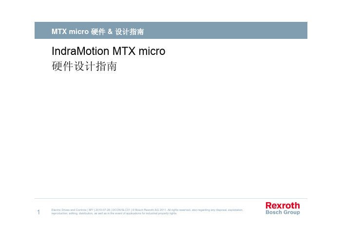
力士乐简明调试
多轴伺服驱动与系统模块 轴3
编码器 轴4
主电源输入 制动电阻 轴2
CF 卡 以太网 HMI
SERCOSIII
11
Electric Drives and Controls | MY | 2010-07-26 | DCCN/SLC31 | © Bosch Rexroth AG 2011. All rights reserved, also regarding any disposal, exploitation, reproduction, editing, distribution, as well as in the event of applications for industrial property rights.
12Leabharlann Electric Drives and Controls | MY | 2010-07-26 | DCCN/SLC31 | © Bosch Rexroth AG 2011. All rights reserved, also regarding any disposal, exploitation, reproduction, editing, distribution, as well as in the event of applications for industrial property rights.
9
Electric Drives and Controls | MY | 2010-07-26 | DCCN/SFA2 | © Bosch Rexroth AG 2011. All rights reserved, also regarding any disposal, exploitation, reproduction, editing, distribution, as well as in the event of applications for industrial property rights.
IndraMotion MTX micro商品说明书
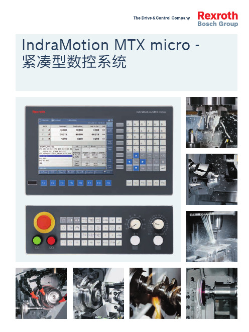
经久耐用的 22mm 开关用于急停,当前操作模式Graphical assistance for every ▲Drilling ▲Milling ▲Contouring ▲Engraving▲Turning 加工循环范例车削加工钻铣轮廓加工雕刻10图形轮廓编辑器IndraMotion MTX micro 轮廓编辑器极大简化了对从简单到复杂轮廓定义的编程。
编辑器引导用户一步步输入轮廓元素。
每一个元素都带有直观的参数输入框。
向导式显示至下一轮廓元素的选项和过渡。
参数的变化及时显示在轮廓图形上。
最后轮廓会以 DIN G 代码的形式保存在 NC 程序中。
功能f轮廓元素:水平 & 垂直线, 角线和正向 & 反向弧线f轮廓元素的数量不受限制f轮廓可定义在子程序中或直接在 NC 程序中f同一 NC 程序中允许多轮廓定义f轮廓输入时有效性检查f在 NC 程序中轮廓以 DIN G 代码写入f可在轮廓编辑结束后再次修改轮廓或手动调整高效 CNC 编程符合 DIN66025 的 NC 编程通用的 NC 编程 - 通过 DIN 编程描述运动顺序及其限制条件(几何形状,运动限制,动态性,偏置等)。
标准的编程用于指定机床的运动和特殊的机床功能。
高级语法的 NC 编程针对更有效的 NC 编程是在符合 DIN 66025 标准 G 代码编程的基础上扩展了功能。
高级语法增强了NC程序的可读性。
例如:scale (全称)或 SCL(缩写)用于放大或缩小已编程的轮廓。
CPL 语言编程(Customer Programming Language)源自 BASIC 高级语言编程,简单易学。
CPL 可以用于变量编程,数学运算,程序结构控制例如通过 REPEAT, WHILE, FOR, IF, CASE, GOTO 和访问系统状态。
通过使用 CPL 您可以:f通过例如循环或类似的程序结构缩短程序量f条件判定的程序f通用子程序用户加工循环使用 DIN 和 CPL 编程创建单独的加工循环。
力士乐IndraMotionMTXmicro针对通用机床的CNC系统解决方案71257CN_03_10
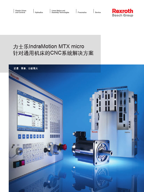
力士乐IndraMotion MTX micro针对通用机床的CNC系统解决方案紧凑、简单、功能强大2力士乐 IndraMotion MTX micro –经济却功能强大今天数控机床市场的多元化对通用机床的CNC系统提出经济有效性的要求。
力士乐成功开发了IndraMotion MTX micro系列通用型CNC系统,它非常适合经济性的应用范围。
力士乐IndraMotion MTX micro 是一款为通用机床市场提供的紧凑、简单、功能强大并且经济的CNC系统解决方案,它由多轴集成伺服驱动,高性能NC控制器和用户友好的人机界面组成。
优势Control City-自动化之城。
来自于自动化之城的IndraMotion MTX micro是针对通用机床的经济型CNC系统解决方案。
••••所有需要的硬件/软件功能都集成在一个核心部件上。
功能强大的32位处理器确保了较短的CNC和PLC处理时间。
它使得IndraMotion MTX micro成为一款最紧凑,并且功能强大的CNC系统。
力士乐成熟的IndraMotion、IndraLogic和IndraDrive技术确保了最高的可靠性和加工精度—甚至达到纳米级。
力士乐全系列产品为您提供全球范围内的服务:- 数控系统- 伺服驱动- 输入/输出外围设备- 液压- 气动- 线性传动技术3IndraMotion MTX micro 为以下设备提供通用的CNC 解决方案功能特性•••••••••••经济型数控车床全机能数控车床车削中心钻床铣床加工中心集成了机床动作的PLC 程序,以及大量可供用户使用的功能模块,实现了完美的交钥匙方案IndraWorks 调试软件减少调试和诊断时间可实现中英文在线切换集成化的加工循环兼容IndraMotion MTX compact 、MTX standard 、MTX performance 和MTX advanced4针对三轴通用机床的应用方案轴15四轴通用机床的应用方案轴2车削-精确和完整IndraMotion MTX micro为您提供标准车削功能6详细功能—工艺铣削-高速和高效IndraMotion MTX micro 为铣削加工提供了完整的功能:扩展功能针对所有加工,许多扩展功能使用相同格式可以被使用:刀具管理进行灵活配置:•••••恒线速切削刚性攻丝主轴-回转轴C 轴功能和动力刀架功能柱面和端面的车铣加工••••扭矩限制自由定义工件坐标系集成的加工循环:车、钻、铣CPL 高级语言提供广泛的功能扩展•••••预读功能缩放和镜像4ms NC 插补时间实时直接从USB 并进行加工倒角功能••••••••最多管理999把刀每把刀两个刀刃几何和磨损补偿刀具寿命管理半径补偿刀尖补偿特殊刀具固定编号/变量编号7位置和加工参数显示刀具列表和刀具编辑器PC 风格的控制系统基于文本信息的诊断HMI 为所有操作提供直观的操作界面:人性化的编辑功能使程序的编写和语法检测更加轻松。
Rexroth—IndraMotion MTX调试手册(简化版)
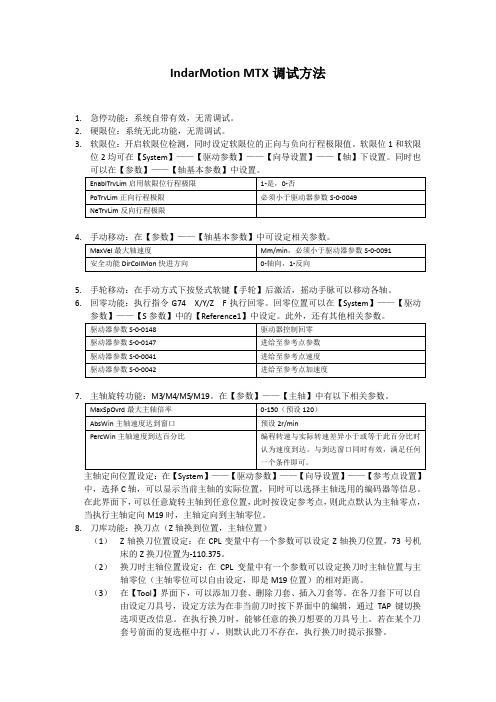
IndarMotion MTX调试方法1.急停功能:系统自带有效,无需调试。
2.硬限位:系统无此功能,无需调试。
3.软限位:开启软限位检测,同时设定软限位的正向与负向行程极限值。
软限位1和软限位2均可在【System】——【驱动参数】——【向导设置】——【轴】下设置。
同时也可以在【参数】——【轴基本参数】中设置。
4.5.手轮移动:在手动方式下按竖式软键【手轮】后激活,摇动手脉可以移动各轴。
6.回零功能:执行指令G74 X/Y/Z F执行回零。
回零位置可以在【System】——【驱动参数】——【S参数】中的【Reference1】中设定。
此外,还有其他相关参数。
7.主轴定向位置设定:在【System】——【驱动参数】——【向导设置】——【参考点设置】中,选择C轴,可以显示当前主轴的实际位置,同时可以选择主轴选用的编码器等信息。
在此界面下,可以任意旋转主轴到任意位置,此时按设定参考点,则此点默认为主轴零点,当执行主轴定向M19时,主轴定向到主轴零位。
8.刀库功能:换刀点(Z轴换到位置,主轴位置)(1)Z轴换刀位置设定:在CPL变量中有一个参数可以设定Z轴换刀位置,73号机床的Z换刀位置为-110.375。
(2)换刀时主轴位置设定:在CPL变量中有一个参数可以设定换刀时主轴位置与主轴零位(主轴零位可以自由设定,即是M19位置)的相对距离。
(3)在【Tool】界面下,可以添加刀套、删除刀套、插入刀套等。
在各刀套下可以自由设定刀具号,设定方法为在非当前刀时按下界面中的编辑,通过TAP键切换选项更改信息。
在执行换刀时,能够任意的换刀想要的刀具号上。
若在某个刀套号前面的复选框中打√,则默认此刀不存在,执行换刀时提示报警。
(4)刀库回零:在手动方式下,按【刀库旋转】(左边这个按键)。
若是出现报警号为602,则是刀库未回零导致的。
(5)换刀宏程序路径:usr/fep/TCH就是换刀宏程序。
(6)宏程序内容:不写,太长。
MX&QX 调试手册(简易中文版)

内供24VDC
监视继电器(综合故障报警触点)(52、53)是常闭触点,故障时断开(53、54)是常开触点,故障时闭合R1(44,45) “关到位反馈”。
常开点,关到位闭合R2(46,47) “开到位反馈”。
常开点,开到位闭合R3(48,49) “关到位反馈”。
常闭点,关到位断开R4(50,51) “开到位反馈”。
常闭点,开到位断开R1-R4每一个触点均可以在设定菜单“更改报警、状态触
点”菜单里面进行组态,可以定义为24种功能的任意一种,且常开、常闭可以任意选择 外供3线控制接线方法,3线保持和3线点动模式在设定菜单里面设
定
)。
内供
目前图纸反应信息为执行机构在全关
位,电源处于断电状态
R5(36,37) “电机超温”。
常开点,故障时闭合
R6(38,39) “远方/就地”。
常开点,故障时闭合
内供24VDC 监视继电器(综合故障报警触点)(52、53)是常闭触点,故障时断开(53、54)是常开触点,故障时闭合R1(44,45) “关到位反馈”。
常开点,关到位时闭合R2(46,47) “开到位反馈”。
常开点,开到位时闭合R3(48,49) “关到位反馈”。
常闭点,关到位时断开R4(50,51) “开到位反馈”。
常闭点,开到位时断开每一个触点均可以在设定菜单“更改报警、状
态触点”菜单里面进行组态,可以定义为的任意一种,且常开、常闭可以任意选择目前图纸反应信息为执行机构在全关位
电源处于断电状态
)。
内供4-20ma 模拟量输出。
17(﹣),18(﹢)。
新蒂平台MT系列精细调节线性阶臂操作手册说明书
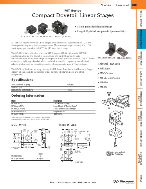
MT-AB2 (M-MT-AB2) MT-CL (M-MT-CL)
Related Products
The MT-CL table clamp securely mounts the MT Series Translation and Rotation Stages directly on tables and breadboards or rail carriers, tilt stages, posts and other components.
Hardened precision rods are preloaded against a four corner hardened slider for smooth, wear-resistant motion. A return spring provides built-in preload to eliminate backlash. The unique carriage design eliminates wobble while providing an extremely robust stage.
.50 (12.7)
.50 (12.7)
.175 (44.5)
1.00 (25.4)
.625 (15.9)
THD A
.50 (12.7)
.50 (12.7)
MS Series
Miniature Linear Stages
• Low profile • Precision 80 TPI adjustment • High load/size ratio • Zero backlash • <0.01 mrad wobble • Over 16 unique configurations
Rexroth IndraDrive Cs ACS01 伺服驱动器 产品手册说明书
Rexroth IndraDrive Cs ACS01伺服驱动器版本03产品手册R912008283Rexroth IndraDrive Cs ACS01伺服驱动器产品手册DOK-INDRV*-ACS01******-PR03-ZH-PRS-6d0559b3a9217a2a0a347e8600d30991-3-zh-CN-7●Rexroth IndraDrive Cs 系统概述●Rexroth IndraDrive Cs 系统组件组合方式说明●Rexroth IndraDrive Cs 系统组件选择●操作规范●系统特性应用说明出版颁发日期备注012020-01第一版022020-04功能新增032020-06参数更新版权© 博世力士乐(西安)电子传动与控制有限公司 2020保留所有权利, 也保留包括任何使用、利用、翻印、编辑、转让以及申请知识产权的权利。
责任规格数据仅用于产品说明,如果未在合同中明确规定,不得视为对特性的保证。
本公司保留关于该文档内容和产品可用性的所有权利。
题目文件类型文件类型代号内部存档附注文件用途更改过程Rexroth IndraDrive Cs ACS01伺服驱动器Rexroth IndraDrive Cs ACS01伺服驱动器 I目录目录页数1 系统介绍 (1)1.1 Rexroth IndraDrive Cs 系列 (1)1.1.1 概述–Rexroth IndraDrive Cs (1)1.1.2 行业应用 (2)1.1.3 特性 (3)1.2 系统配置 (5)1.2.1 系统结构 (5)1.2.2 驱动器组件 (6)2 安全使用说明 (9)2.1 合理使用 (9)2.1.1 使用须知 (9)2.1.2 应用场合 (9)2.2 不当使用 (10)2.3 使用安全说明 (10)2.3.1 安全使用要求 (10)2.3.2 使用不当引发的危险 (10)2.3.3 与电气元件和外壳接触的防护 (10)2.3.4 危险动作的防护 (11)2.3.5 与高温部件接触的防护 (12)2.3.6 电池安全 (12)2.4 警示词和安全提示符号 (13)3 组件组合 (15)3.1 各组件简介 (15)3.1.1 ACS01---简要说明及设计构成 (15)3.2 配置驱动系统 (15)3.2.1 伺服驱动器 (15)3.2.2 设备功能 (16)3.2.3 电机 (16)3.2.4 电机电缆 (21)3.3 安装条件 (21)3.3.1 安装条件与操作环境 (21)3.3.2 控制柜设计结构与散热 (24)3.4 机械项目规划 (25)3.4.1 驱动器 (25)3.5 电气项目规划 (31)3.5.1 连接图 (31)3.5.2 控制电压项目规划 (32)3.5.3 电源连接电源电压 (36)3.5.4 直流母线耦合 (60)3.6 验收测试及认证 (67)R912008283_版本03 Bosch Rexroth AG页数4供货、标签、运输及存放 (69)4.1 供货................................................................................... 694.1.1 出厂测试.............................................................................. 694.1.2 用户测试.............................................................................. 694.2 标签................................................................................... 704.2.1 铭牌.................................................................................. 704.2.2 包装清单.............................................................................. 714.3 组件运输............................................................................... 724.4组件存放 (72)5安装 (73)5.1 控制柜内安装ACS01...................................................................... 735.2 电气连接............................................................................... 745.2.1 连接图................................................................................ 745.2.2 连接点................................................................................ 755.2.3 板载连接点............................................................................ 765.2.4设计与安装过程中的电磁兼容措施 (96)6组件参数 (105)6.1 控制单元.............................................................................. 1056.1.1 EC-多类型编码器接口.................................................................. 1056.1.2 ET-多协议实时以太网网口.............................................................. 1296.1.3 数字量输入/输出...................................................................... 1356.1.4 电压型模拟量输入..................................................................... 1406.1.5 电流型模拟量输入..................................................................... 1416.1.6 模拟量输出........................................................................... 1416.1.7 继电器触点........................................................................... 1426.2 控制面板.............................................................................. 1436.2.1 设计................................................................................. 1436.3 电源.................................................................................. 1446.3.1 控制电压............................................................................. 1446.3.2 电源电压............................................................................. 1456.3.3 直流母线............................................................................. 1496.3.4 集成制动电阻......................................................................... 1516.3.5逆变器 (151)7电缆、配件及附加组件 (155)7.1 概述.................................................................................. 1557.1.1 电缆................................................................................. 1557.1.2 配件................................................................................. 1557.1.3 附加组件............................................................................. 1567.2 配件.................................................................................. 1577.2.1 安装及配件连接(HAS09).............................................................. 1577.2.2 直流母线连接器(RLS0778/K06)........................................................ 1637.2.3RKB0013,以太网通讯 (164)II 目录Rexroth IndraDrive Cs ACS01伺服驱动器Bosch Rexroth AG R912008283_版本03Rexroth IndraDrive Cs ACS01伺服驱动器 III目录页数7.3 附加组件 (165)7.3.1 电源滤波器NFD / NFE (165)7.3.2 电源电抗器 (168)7.3.3 HLR外部制动电阻 (172)7.3.4 直流侧电容单元HLC (179)8 环境保护及废弃处置 (183)8.1 环境保护 (183)8.2 废弃处置 (183)9 服务与支持 (185)10 附录 (187)10.1 电缆横截面及保险丝尺寸选型 (187)10.2 测量泄露电容 (194)10.3 电容泄露 (195)10.3.1 电机电容泄露 (195)10.3.2 电力电缆电容泄露 (196)索引 (199)R912008283_版本03 Bosch Rexroth AGIV Rexroth IndraDrive Cs ACS01伺服驱动器Bosch Rexroth AG R912008283_版本03Rexroth IndraDrive Cs ACS01伺服驱动器 1/201系统介绍1 系统介绍1.1 Rexroth IndraDrive Cs 系列1.1.1 概述–Rexroth IndraDrive Cs表格1-1:Rexroth IndraDrive Cs 系列组件R912008283_版本03 Bosch Rexroth AG1.1.2行业应用通用自动化、搬运、组装自动化组装及搬运系统码垛系统、取放系统、物流......机床小型机(例如木材加工)、辅机......食品及包装行业灌装及密封、码垛、装箱、封箱、贴标......印刷机械标签打印、贴标、数字印刷、定位......半导体行业半导体/晶圆生产、处理、金属化、清洗、太阳能电池生产......表格1-2:目标应用2/201系统介绍Rexroth IndraDrive Cs ACS01伺服驱动器Bosch Rexroth AG R912008283_版本031.1.3 特性功能特性●结构紧凑●防护等级IP20●具有存储和控制功能的操作面板●多类型编码器接口支持多种主流编码器(ACUROlink、HIPERFACE®、EnDat2.1、EnDat2.2、SSI、TTL、 sin/cos 、旋转变压器、MS2N 编码器、MSC编码器 )●直流母线连接●1个模拟量输入 (14位, ±10 V)●8个数字量输入–2个探针输入–1个组合式数字量端口,可配置为数字量输入或输出●可调节的风扇控制●集成制动电流测量和监控●电机输出端绕组短路触发停机保护机制●支持MSC永磁同步伺服电机●霍尔传感器适配盒SHL03.1,用于操作带有数字霍尔传感器的MCL直线电机性能特征规格(宽:50 mm;高:215 mm)规格(宽:70 mm;高:268 mm)规格(宽:130 mm;高:268 mm)ACS1-W00...→0818283654主电源V 3 AC 200 … 500 V最大输出电流(4kHz)A rms818283654表格1-3:ACS01伺服驱动器规格参数Rexroth IndraDrive Cs ACS01伺服驱动器 3/201系统介绍R912008283_版本03 Bosch Rexroth AG接口概述●兼容IndraDrive 平台●支持以下协议的实时以太网通讯:–sercos III –EtherCAT(SoE)–EtherCAT(CoE)–PROFINET IO –EtherNet/IP●多类型编码器接口●模拟量输入●可自由配置的数字量输入/输出可用编码器可用编码器供电电压为5 V 和12 V 的编码器:●MSC 电机编码器●MSK 电机编码器●MS2N 电机编码器●ACUROlink 编码器●1V pp 正弦编码器,HIPERFACE®●1V pp 正弦编码器,EnDat 2.1、EnDat 2.2●1V pp 正弦编码器(配置参考信道)●省线式TTL 编码器●SSI●组合式编码器SSI(SSI 及1V pp 正弦编码器)●旋转变压器●SHL02.1霍尔传感器适配盒●数字霍尔传感器与SHL03.1霍尔传感器适配盒可配合使用4/201系统介绍Rexroth IndraDrive Cs ACS01伺服驱动器Bosch Rexroth AG R912008283_版本031.2系统配置1.2.1系统结构*可选项24V 控制电压COM 通讯DST 自耦变压器F 保险丝ACS01伺服驱动器HLC 直流母线电容单元(用于连接直流母线的设备)HLR 外部制动电阻HNL 电源电抗器NF 电源滤波器K1外部电源接触器M 电机RB内部制动电阻(位于驱动器后方)插图1-1:Rexroth IndraDrive Cs 驱动系统系统介绍系统介绍1.2.2 驱动器组件ACS01 伺服驱动型号系统介绍表格1-4:ACS01型号说明HAP01 键盘图示插图1-2:HAP01 键盘型号表格1-5:HAP01型号说明系统介绍2安全使用说明2.1合理使用2.1.1使用须知Bosch Rexroth 产品代表着先进的开发和制造水平。
Rexroth IndraMotion for Trans单轴金属切割解决方案简介说明书
T0 (no tool), T1 .. T20 (tool length offset)
Dwell timer
Feed to positive stop
PLC interface: I/O, Profibus, DeviceNet, Ethernet/IP i.p.
Absolute multi-turn feedback w/o battery (MSK)
for compatible Trans-01 retrofit solutions but also for new
applications - whenever single axis metal cutting axis is
required using the latest technology and connectivity.
Electrical Enclosure
T R TTA VDN MMS 0 1
PLC system
Digital I/O‘s
TAM
Machine Station MAC Motor
IndraMotion for Trans – latest technology
Solutions for at the machine installation can be created by putting the IndraDrive C and VCP08 HMI with Trans-01 functionality into a compact enclosure. Connectivity to the machine PLC can be digital I/O or Fieldbus reducing wiring.
Rexroth 驱动技术产品手册
1/8For information regarding the available spare parts see:/spcPressure relief valve,pilot operatedType DB . KNominal sizes 6 and 10Component series 4XMaximum operating pressure 315 bar Maximum flow 60 l/min (NS6) 100 l/min (NS10)RE 25731/10.05Replaces: 08.03Overview of contentsMerkmale 1Ordering details 2Preferred types2Function, section, symbol 3T echnical data 3Characteristic curves 4Unit dimensions – NS6 5Cavity – NS66Unit dimensions – NS10 7Cavity – NS108Features– Cartridge valve – 4 pressure stages– 4 adjustment types, optional:• Rotary knob• Sleeve with hexagon and protective cap • Lockable knob with scale • Rotary knob with scaleK4278-1FeaturesOrdering detailsscope of supply.Nominal size 6Type Material No. DB 6 K2-4X/50YV R900487903 DB 6 K2-4X/100YV R900483440 DB 6 K2-4X/200YV R900486196 DB 6 K2-4X/315YV R900483441Nominal size 10Type Material No. DB 10 K2-4X/50YV R900422817 DB 10 K2-4X/100YV R900453240 DB 10 K2-4X/200YV R900438123 DB 10 K2-4X/315YV R900438126Preferred typesFunction, section, symbolPressure valves type DB..K.. are pilot operated pressure relief valves for installation in manifolds. They are used to limit the pressure in a hydraulic system. Setting of the system pressure is via adjustment element (4).At rest, the valves are closed. Pressure in the main port 1 acts on the spool (1). At the same time, pressure is passed through orifice (2) onto the spring loaded side of the spool (1) and through orifice (3) to the pilot poppet (6). If the pressure in main port 1 rises above the value set at spring (5), then the pilot poppet opens (6). Pressure fluid can now flow from the spring loaded side of the spool (1), through the orifice (3) andchannel (7) into main port 3. The resulting pressure drop moves piston (1) causing this to open the main port from 1 to 2, whilst the pressure set at spring (5) is maintained. Pilot oil drain from the two spring chambers is taken externally via main port 3.Back pressures (main port 3) are added to the set pressure.1)The maximum operating pressure results from 2) The cleanliness class stated for the components must beadhered to in hydraulic systems. Effective filtration preventsTechnical data (for applications outside these parameters, please consult us!)GeneralNominal size 610Weight kgApprox. 0.15Approx. 0.2InstallationOptional Ambient temperature range°C –20 to +80HydraulicMax. operating pressure 1)– Main port 1 (P)bar 315Max. settable pressure – Main port 1 (P)bar 50; 100; 200; 315Max. permissible back pressure 1) – Main port 2 (T)bar 315– Main port 3 (Y)bar 315Maximum flow l/min60100Pressure fluidMineral oil (HL, HLP) to DIN 51524; fast bio-degradable pressue fluids to VDMA 24568 (also see RE 90221); HETG (rape seed oil); HEPG (polyglycole); HEES (synthetic ester); other pressure fluids on request Pressure fluid temperature range °C –20 to +80Viscosity rangemm 2/s 10 to 800Maximum permissible degree of pressure fluid contamination Cleanliness class to ISO 4406 (c)Class 20/18/15 2)faults from occurring and at the same time increases the component service life.For the selection of filters see data sheets RE 50070, RE 50076, RE 50081, RE 50086 and RE 50088.3 = Main port 3 (Y)1020304050605010020031535001020304050605101520020406080100501002003153500204060801005101520Characteristic curves – NS6 (measured with HLP46, ϑoil = 40 °C ± 5 °C)Flow in l/min →S e t t a b l e p r e s s u r e i n b a r →Flow in l/min →M i n . s e t t a b l e p r e s s r u e i n b a r →p E -q V -characteristic curvesp E min -q V-characteristic curvesThe characteristic curves are valid for an outlet pressure = zero over the entire flow range!Characteristic curves – NS10 (measured with HLP46, ϑoil = 40 °C ± 5 °C)Flow in l/min →S e t t a b l e p r e s s u r e i n b a r →Flow in l/min →M i n . s e t t a b l e p r e s s u r e i n b a r →p E -q V -characteristic curvesp E min -q V-characteristic curvesThe characteristic curves are valid for an outlet pressure = zero over the entire flow range!Unit dimensions – NS6 (nominal dimensions in mm)1Adjustment type "1"2Adjustment type "2"3Adjustment type "3"4Adjustment type "7"5Space required to remove the key6Locknut 24A/F7 Hexagon 10A/F8Key width 24A/F, tightening torque M= 50 NmA1 = Main port 1 (P)2 = Main port 2 (T)3 = Main port 3 (Y)LS = Location ShoulderCavity – NS6; 3 main ports; thread M20 x 1 (nominal size in mm)1 = Main port 1 (P)2 = Main port 2 (T), location; optional about the circumference3 = Main port 3 (Y)LS = Location Shoulder1) Depth of fitUnit dimensions – NS10 (nominal dimensions in mm)1Adjustment type "1"2Adjustment type "2"3Adjustment type "3"4Adjustment type "7"5Space required to remove the key6Locknut 24A/F7 Hexagon 10A/F8Hexagon 30A/F, tightening torque MA = 50 Nm1 = Main port 1 (P)2 = Main port 2 (T)3 = Main port 3 (Y)LS = Location ShoulderBosch Rexroth AGHydraulicsZum Eisengießer 197816 Lohr am Main, GermanyT elefon +49 (0) 93 52 / 18-0T elefax +49 (0) 93 52 / 18-23 58 documentation@boschrexroth.de www.boschrexroth.de © This document, as well as the data, specifications and other informations set forth in it, are the exclusive property of Bosch Rexroth AG. Without their consent it may not be reproduced or given to third parties.The data specified above only serves to describe the product. No statements concerning a certain condition or suitability for a certain application can be derived from our information. The details stated do not release you from the responsibility for carrying out your own assessment and verification. It must be remembered that our products are subject to a natural process of wear and ageing.Cavity – NS10; 3 main ports; thread M20 x 1 (nominal dimensions in mm)1 = Main port 1 (P)2 = Main port 2 (T), location: optional about the circumference3 = Main port 3 (Y)LS = Location Shoulder1) Depth of fit。
如何使用IndraMotion MTX micro来配置双通道工程
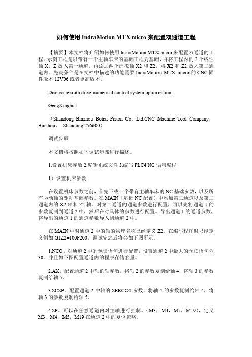
如何使用IndraMotion MTX micro来配置双通道工程【摘要】本文档将介绍如何使用IndraMotion MTX micro来配置双通道的工程。
示例工程是以带有一个主轴车床的基础工程为基础,并将工程内的2个线性轴X,Z放入第一通道,再添加两个虚拟轴X2和Z2,将X2和Z2放入第二通道内。
先决条件是在文档中描述的功能需要IndraMotion MTX micro的CNC固件版本12V06或者更高版本。
Discuss rexroth drive numerical control system optimizationGengXinghua(Shandong Binzhou Bohai Piston Co,C Machine Tool Company,Binzhou,Shandong 256600)调试步骤本文档将按照如下调试步骤进行描述。
1.设置机床参数2.编辑系统文件3.编写PLC4.NC语句编程1)设置机床参数在设置机床参数之前,首先下载一个带有主轴车床的NC基础参数,以及所有驱动轴的驱动基础参数。
在MAIN(基础NC配置)中添加第二通道以及第二通道内的X2轴和Z2轴。
对第二通道的通道参数进行配置,可以先将通道1的参数复制到通道2中,然后在对具体的参数进行配置。
导出通道1的通道参数,将导出的通道1的通道参数导入到通道2中。
在MAIN中对通道2中的轴的物理名称已经定义Z2。
在编写程序时只能定义例如G1Z2=100F200,调试完之后将会如下图所示。
1.NCO。
对通道2中的预读语句进行配置,设置通道2中最大的预读语句为30。
并且如下图配置通道内的程序存储容量。
2.AX。
配置通道2中轴的轴参数,将轴2的参数复制给轴4,将轴3的参数复制给轴5。
3.SCSP。
配置通道2中轴的SERCOS参数,将轴2的参数复制给轴4,将轴3的参数复制给轴5。
4.SP。
可以在任意通道内对主轴进行控制。
(M3,M4,M5,M19),定义M3,M4,M5,M19在通道2中的复位策略。
- 1、下载文档前请自行甄别文档内容的完整性,平台不提供额外的编辑、内容补充、找答案等附加服务。
- 2、"仅部分预览"的文档,不可在线预览部分如存在完整性等问题,可反馈申请退款(可完整预览的文档不适用该条件!)。
- 3、如文档侵犯您的权益,请联系客服反馈,我们会尽快为您处理(人工客服工作时间:9:00-18:30)。
IndarMotion MTX调试方法
1.急停功能:系统自带有效,无需调试。
2.硬限位:系统无此功能,无需调试。
3.软限位:开启软限位检测,同时设定软限位的正向与负向行程极限值。
软限位1和软限
位2均可在【System】——【驱动参数】——【向导设置】——【轴】下设置。
同时也可以在【参数】——【轴基本参数】中设置。
4.
5.手轮移动:在手动方式下按竖式软键【手轮】后激活,摇动手脉可以移动各轴。
6.回零功能:执行指令G74 X/Y/Z F执行回零。
回零位置可以在【System】——【驱动
参数】——【S参数】中的【Reference1】中设定。
此外,还有其他相关参数。
7.
主轴定向位置设定:在【System】——【驱动参数】——【向导设置】——【参考点设置】中,选择C轴,可以显示当前主轴的实际位置,同时可以选择主轴选用的编码器等信息。
在此界面下,可以任意旋转主轴到任意位置,此时按设定参考点,则此点默认为主轴零点,当执行主轴定向M19时,主轴定向到主轴零位。
8.刀库功能:换刀点(Z轴换到位置,主轴位置)
(1)Z轴换刀位置设定:在CPL变量中有一个参数可以设定Z轴换刀位置,73号机床的Z换刀位置为-110.375。
(2)换刀时主轴位置设定:在CPL变量中有一个参数可以设定换刀时主轴位置与主轴零位(主轴零位可以自由设定,即是M19位置)的相对距离。
(3)在【Tool】界面下,可以添加刀套、删除刀套、插入刀套等。
在各刀套下可以自由设定刀具号,设定方法为在非当前刀时按下界面中的编辑,通过TAP键切换
选项更改信息。
在执行换刀时,能够任意的换刀想要的刀具号上。
若在某个刀
套号前面的复选框中打√,则默认此刀不存在,执行换刀时提示报警。
(4)刀库回零:在手动方式下,按【刀库旋转】(左边这个按键)。
若是出现报警号为602,则是刀库未回零导致的。
(5)换刀宏程序路径:usr/fep/TCH就是换刀宏程序。
(6)宏程序内容:
不写,太长。
(7)相关换刀指令:
9.注意事项:Rexroth-IndraMotion MTX启动必须要CF卡,CF卡内存储这个系统及驱动中
的数据,同时系统启动需要CF引导,无此卡系统无法启动。
10.维修人员密码:123456
IndraMotion MTX相关参数
IndraMotion MTX micro系统图解
由于图片过大,导致整个DOC文件过大无法上传,故将
图片删除,同时删除部分内容。
1.IndraMotion MTX micro集成驱动:以下所有图均可复制出来放大查看。
在这个集成驱动上,可以连接4个轴,X/Y/Z/主轴以及输入输出接口、编码器接口、网络接口、通讯接口等。
可以将图放大观察各接口详细情况。
2.CF卡:此卡极度重要,存储系统数据及作为系统启动引导盘,无此卡整台系统报废。
3.切换参数与参数树之间的TAP键:
4.CPL变量:可以设置Z轴换刀位置,主轴换刀位置、刀具总数及其他相关参数。
5.刀具页面:此页面下可以设定各刀套对应的刀具号,也可以在PB框中打√号,表示消
除此刀,消除后换此刀时系统会产生报警:刀具号不存在。
6.刀具编辑页面:进入此页面下编辑刀具相关内容。
7.设置向导:进入设置向导中可以设定机床零点及主轴零点和查看各轴实时信息。
