CISCO UCS_C210操作系统安装手册
Cisco UCS C240服务器安装与维护指南说明书
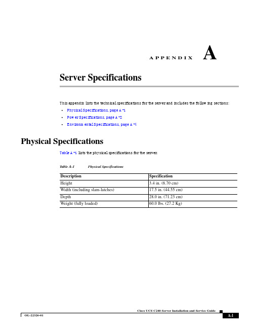
A P P E N D I X AServer SpecificationsThis appendix lists the technical specifications for the server and includes the following sections:•Physical Specifications, page A-1•Power Specifications, page A-2•Environmental Specifications, page A-4Physical SpecificationsTable A-1 lists the physical specifications for the server.Table A-1Physical SpecificationsDescription SpecificationHeight 3.4 in. (8.70 cm)Width (including slam-latches)17.5 in. (44.55 cm)Depth28.0 in. (71.23 cm)Weight (fully loaded)60.0 lbs. (27.2 Kg)Appendix A Server Specifications Power SpecificationsPower SpecificationsThe power specifications for the two power supply options are listed in the following sections:•650 W AC Power Supply, page A-2•1200 W AC Power Supply, page A-3•930W DC Power Supply, page A-3You can get more specific power information for your exact system configuration by using the CiscoUCS Power Calculator:650 W AC Power SupplyTable A-2 lists the specifications for each 650 W power supply (Cisco part number UCSC-PSU-650W).Table A-2Power Supply SpecificationsDescription SpecificationAC input voltage Nominal range: 100–120 VAC, 200–240 VAC(Range: 90–132 VAC, 180–264 VAC)AC input frequency Nominal range: 50 to 60Hz(Range: 47–63 Hz)Maximum AC input current7.6 A at 100 VAC3.65 A at 208 VACMaximum input volt-amperes760 VA at 100 VACMaximum output power per PSU650 WMaximum inrush current33 A (sub-cycle duration)Maximum hold-up time12 ms at 650 WPower supply output voltage12 VDCPower supply standby voltage 3.3 VDCEfficiency rating Climate Savers Platinum Efficiency (80Plus Platinumcertified)Form factor RSP1Input connector IEC60320 C14Appendix A Server SpecificationsPower Specifications1200 W AC Power SupplyTable A-3 lists the specifications for each 1200 W power supply(Cisco part number UCSC-PSU2-1200).Table A-3Power Supply SpecificationsDescription SpecificationAC input voltage Nominal range: 100–120 VAC, 200–240 VAC(Range: 90–132 VAC, 180–264 VAC)AC input frequency Nominal range: 50 to 60Hz(Range: 47–63 Hz)Maximum AC input current11 A at 100 VAC7 A at 200 VACMaximum input volt-amperes1456 VAMaximum output power per PSU800 W at 90–180 VAC1200 W at 180–264 VACMaximum inrush current30 A (sub-cycle duration)Maximum hold-up time12 ms at 1200 WPower supply output voltage12 VDCPower supply standby voltage12 VDCEfficiency rating Climate Savers Platinum Efficiency (80Plus Platinumcertified)Form factor RSP1Input connector IEC60320 C14930W DC Power SupplyTable A-4 lists the specifications for each 930 W DC power supply(Cisco part number UCSC-PSU-930WDC).Table A-4930 W DC Power Supply SpecificationsDescription SpecificationDC input voltage range Nominal range: –48 to –60 VDC nominal(Range: –40 to –60 VDC)Maximum DC input current23 A at –48 VDCMaximum input W1104 WMaximum output power per PSU930 WMaximum inrush current35 A (sub-cycle duration)Maximum hold-up time8 ms at 930 WPower supply output voltage12 VDCAppendix A Server SpecificationsEnvironmental SpecificationsEnvironmental SpecificationsTable A-5 lists the environmental specifications for the server.Power supply standby voltage 12 VDCEfficiency rating > 92% at 50% load Form factor RSP1Input connectorRemovable connector block UCSC-CONN-930WDC=Table A-4930 W DC Power Supply SpecificationsDescriptionSpecification Table A-5Environmental SpecificationsDescriptionSpecificationTemperature, operating:41 to 104°F (5 to 40°C)Derate the maximum temperature by 1°C per every 305 meters of altitude above sea level.Temperature, non-operating (when the server is stored)–40 to 149°F (–40 to 65°C)Humidity (RH), noncondensing 10 to 90%Altitude, operating 0 to 10,000 feet Altitude, non-operating (when the server is stored)0 to 40,000 feetSound power level Measure A-weighted per ISO7779 LwAd (Bels)Operation at 73°F (23°C)5.8Sound pressure level Measure A-weighted per ISO7779 LpAm (dBA)Operation at 73°F (23°C)43。
思科CISCO设备的基本操作详解

CISCO设备的基本操作网络设备交换机、路由器、防火墙、VPN……..共同特性有智能,能识别数据报文中的控制信息,对数据进行定向转发。
交换机能识别数据帧中的MAC地址信息,在同一网段转发数据。
效率比集线器高。
默认工作在第二层。
主要用于组建局域网。
路由器能识别数据报文中的第三层信息(IP地址),在不同网段转发数据。
主要用于连接局域网和广域网。
路由器的内部组件:主板 CPU 存贮系统接口存贮系统ROM 只读存贮器基本的引导文件 1 →FLASH 闪存操作系统IOS 2 → RAM 随机存贮器 NV RAM 非易失内存配置文件 3→启动顺序寄存器的值( 注册表)正常 1 2 3 0X2102特殊 1 2 0X2142 跳过配置文件(用于密码的恢复)路由器的接口类型:Router>sh ip int briefInterface IP-Address OK? Method Status ProtocolFastEthernet0/0 unassigned YES unset administratively down downFastEthernet0/1 unassigned YES unset administratively down downSerial0/0 unassigned YES unset administratively down downSerial0/1 unassigned YES unset administratively down downSerial0/2 unassigned YES unset administratively down downSerial1/0 unassigned YES unset administratively down downSerial1/1 unassigned YES unset administratively down downSerial1/2 unassigned YES unset administratively down downSerial1/3 unassigned YES unset administratively down down一、局域网接口RJ-45 (以太网接口)100M F0/0 F0/1 fast ethernet 模块化设备2600以上1000M G0/0 G0/110G Ten3/1二、广域网接口异步串行口(用于异步拨号网络,淘汰)同步串行口( 用于DDN和帧中继网络)(铜缆)2Mserial S0 S1 S0/0 S0/1V.24 最大支持64K 淘汰V.35 可支持64k-2MPOS接口(packet over SDH)POS 1/0/0 POS 1/0/1 SDH专线(光纤)155M插槽/模块/接口2M、4M、8M、10M…. 155M…622M …2.5G…10G…40G设备的登录在网络管理中,希望这些网络设备按我们的要求去工作→指令(相关参数)控制台console 命令行网络 1. telnet 命令行2. SDM WEB页面一.控制台方式登录。
思科C20管理员手册
思科 C20 系统手册
2010 年 3 月
目
1
录
TANDBERG C20 产品手册 ........................................................................................................... 3 1.1 1.2 TANDBERG C20 产品介绍.................................................................................................... 3 TANDBERG C20 安装标准.................................................................................................... 4 设备标准连接 .................................................................................................................. 4 会场标准布局 .................................................................................................................. 5 网络环境 .......................................................................................................................... 7 会场环境 .......................................................................................................................... 7
CISCO服务器Linux系统安装步骤
开机进入CISCO LOGO界面,按ESC,进入DOS界面。
根据提示,按CTRL+C进入RAID界面。
在RAID界面的Adapter下选择1064E,单击回车。
选择RAID Properties,点击回车。
选择Create IM Volume。
在Slot Num行中,把光标移至RAID DISK下,点击“+”。
按D选择,Overwrite existing data, create a new IM array ALL DATA on ALL disks in the array will be DELETED!! No Synchronization performed.服务器自动调回前一步界面,但Slot Num项下的RAID DISK已经由原先的NO变为YES。
把光标移至下行,Slot Num 1的RAID DISK选项,点击“+”,服务器自动按最近一次配置把NO转换成YES。
此时,Drive Status下,Slot Num 0 已经变为Primary, Slot Num 1 变为Secondary,按C,选择保存改变并退出目录。
服务器自动进行RAID操作,操作完毕后,按两次ESC键,选Exit the Configuration Utility and Reboot选项,服务器将重启。
2.1.2Linux系统安装及设置系统统一安装Red Hat Enterprise Linux 5.4,启动机器插入光盘。
在Welcome to Red Hat Enterprise Linux Server的CD found中,选择“SKIP”进。
进入安装界面后点击“NEXT“,在安装语言选择栏里选择语言为“简体中文”后,点击“NEXT”。
键盘选项选择“美国英语式”,点击“NEXT”,弹出“安装号码”窗口,选择“跳过输入安装号码”后“确认”,在“跳过”界面继续选择“跳过”,在“警告”窗口选择“是”。
进入分区界面,在下拉菜单中选择“建立自定义的分区结构”后点击“下一步”。
思科UCS安装部署手册
Cisco Unified Computing System(统一计算系统)思科UCS安装部署手册目录目录1概述 (3)编写目的 (3)文档适用人员 (3)实施原则 (3)2网络设计 (5)UCS系统网络设计(可根据实际情况修改) (5)3实施方案设计 (7)控制器设备命名参数表 (7)设备登录信息表 (7)IP地址规划表 (7)硬件配置信息 (8)3.4.1Fabric Interconnect mode信息表 (8)3.4.2Fabric Interconnect port角色信息表 (9)3.4.3设备连接信息表 (11)3.4.4Port Channel信息表 (13)服务配置信息 (13)3.5.1Service profile信息表 (13)3.5.2MAC pool信息表 (14)3.5.3WWNN pool信息表 (15)3.5.4WWPN pool信息表 (15)3.5.5UUID Suffix pool信息表 (15)3.5.6VLAN信息表 (15)策略信息 (16)3.6.1Local Disk (16)3.6.2Boot策略 (16)4实施过程 (18)6248XP初始化 (18)4.1.16248XP接线准备 (18)4.1.26248XP 初始化6248XP-A (18)4.1.36248XP初始化6248XP-B (19)4.1.4登陆UCS Manager (19)刀箱发现 (20)4.2.1配置刀箱发现策略 (20)4.2.2配置存储上联口 (20)4.2.3配置网络上联口 (22)4.2.4配置刀箱下联口 (23)4.2.5刀箱发现状态 (23)刀片管理IP配置 (24)资源池和策略配置 (25)4.4.1UUID Pool (25)4.4.2MAC Pool (28)4.4.3WWNN POOL (29)4.4.4WWPN Pool (31)4.4.5Vlan定义 (34)4.4.6Local Disk Raid策略 (36)4.4.7Boot启动策略 (37)创建Service Profile(根据现场实施画面更改) (39)关联Service Profile到指定的刀片服务器上 (48)刀片服务器的操作系统安装 (51)4.7.1KVM Console (51)4.7.2操作系统安装 (55)4.7.3操作系统驱动安装 (57)1概述编写目的本文的是铁姆肯虚拟化平台UCS部分的项目技术实施的详细描述和规划,撰写本文的目的是在实际实施工作前,将所有实施步骤、方法和各方需完成的任务明确。
UCSC安装手册
UCS C系列机架服务器安装手册Version 1.1撰写人:Ian Liu System EngineerAnHui Harme Science&Technology Co.,Ltd刘寅系统工程师安徽华脉科技发展有限公司yliu@UCS C-Series Rack Servers Installer Guide (1)一、物理设备安装 (3)1.1 服务器硬件安装 (3)1.2 服务器内存安装 (4)1.3 LSI 9261阵列卡安装配置 (9)1.4 LSI MegaRAID 配置方法 (10)1.5 进行板载ICH10R SATA RAID的配置 (20)二、操作系统安装 (40)1、连接准备工作 (40)2、设置DHCP服务器 (41)3、开电源获取CIMC的IP地址 (41)4、登陆CIMC管理界面 (42)5、更改CIMC管理地址 (43)6、重新登录CIMC管理接口,升级CIMC固件 (44)7、点击Launch KVM Console (51)8、安装操作系统 (51)VMware vSphere5安装 (51)工具下载地址 (62)Windows系统安装 (64)一、物理设备安装1.1 服务器硬件安装思科UCS C系列机架式服务器安装硬盘时需要注意硬盘安装托架,用力按压托架上的按钮,然后将托架抽出,然后插入新硬盘即可,注意最后扣好拉手,观察是否安装完成。
VGA排线在实际工作中,发现当我们使用了前置的console口扩展的KVM线缆之后,我们经常使用的后置的VGA就没有了输出信号,对于用户来说,机柜后侧才是各种线缆的走线方向,对于只是想通过前置KVM扩展两个USB端口的话,我们只需要打开上面的面板,拔出前置输出的VGA排线。
这样前置的VGA就不再输出信号,也不会影响后面的VGA信号输出,前面扩展的USB也可以正常使用。
1.2 服务器内存安装由于思科自有研发的大内存扩展技术,使用自己的内存管理芯片,加之Intel E5家族CPU的发布,业界CPU的内存控制数量都随之翻倍,思科与其他厂商的内存插槽插法也有不同。
思科Cisco交换机配置手册配置教程
思科Cisco交换机配置手册配置教程配置接口特性这一章详细说明交换机上的接口和描述怎么配置他们。
这章有以下这些内容:●理解接口类型●使用接口命令●配置二层接口●监控和维护第二层接口●配置第三从接口注意:需要完整的有关该章的语法和应用信息,请参考Catalyst 3550 Multilayer Switch Command Reference和Cisco IOS Interface Command Referencefor Release 12.1.理解接口类型这个部分描述了不同的接口类型,以及其它章节所包括的详细配置这些接口的一些参考内容。
其他章节描述了物理接口特性的配置过程。
这部分包括:基于端口的VLAN (Port-Based VLANs)交换端口(Switch Ports)以太网通道端口组(EtherChannel Port Groups)交换虚拟接口(Switch Virtual Interfaces)被路由端口(Routed Ports)连接接口(Connecting Interfaces)基于端口的VLAN (Port-based Vlans)一个Vlan是一个按功能、组、或者应用被逻辑分段的交换网络,并不考虑使用者的物理位置。
要更多关于Vlan的信息请看“Configuring VLANS”。
一个端口上接受到的包被发往属于同一个Vlan的接收端口。
没有一个第三层的设备路由Vlan间的流量,不同Vlan的网络设备无法通讯。
为了配置普通范围(Normal-range) Vlan(Vlan IDs 1-1005),使用命令:config-vlan模式(global) vlan vlan-id或vlan-configuration模式(exec) vlan database针对Vlan ID 1-1005的vlan-configration模式被保存在vlan数据库中。
为配置扩展范围(extended-range)Vlans (Vlan ID 1006-4094),你必须使用config-vlan模式,并把VTP的模式设为transparent透明模式。
Cisco设备安装指南

Distribution 一般不会本层使用. Layer
分布层
提供访问层与分布层之间的连接. 提供从分 布层到核心层的连接. 提供从服务器群到核 心层的连接.
Co核re心L层ayer 一般不会在本层使用.
提供交换机间的互连.
以太网介质比较
10BaseT
双工型介质接口 连接器 (MIC) ST
区分不同的连接类型
棕 棕 绿 蓝蓝 绿 橙橙 白白 白白
两端的线序相同
UTP实现交叉线
交叉连接10BaseT/ 100BaseT
交叉线
集线器/交换机
针线 1 RD+ 2 RD3 TD+ 4 NC 5 NC 6 TD7 NC 8 NC
集线器/交换机
针线 1 RD+ 2 RD3 TD+ 4 NC 5 NC 6 TD7 NC 8 NC
DTE
Data Communications Equipmen 数据通讯设备
• WAN服务商方的最后通讯设备 • DCE提供时钟
DCE
调制解调器 通道服务单元/ 数据服务单元
SS
S
S
SS
DTE
DCE
DCE
DTE
• DTE/DCE—责任分界点
固化的端口
2500 路由器—背板一览
WAN串口可以采用固化方式
图例
快速以太网/ 以太网 ISDN 专线
核心 服务器
ISDN 云
专线/ 帧中继
WAN物理层实现
• 物理层实现多种多样 • 连线规范定义了连接速率
HDLC PPP 帧中继
EIA/TIA-232 EIA/TIA-449 X.121 V.24 V.35
HSSI
UCS系统部署技术手册,UCS,Cisco
UCS系统部署技术手册,UCS,Cisco UCS系统部署技术手册UCS,Cisco1.简介1.1 本文档目的1.2 UCS系统概述1.3 UCS系统部署流程概述2.系统规划和设计2.1 硬件规划2.1.1 服务器选型和配置2.1.2 网络设备选型和配置2.2 软件规划2.2.1 UCS Manager版本选择2.2.2 UCS软件部署架构设计2.3 安全性规划2.3.1 访问控制策略2.3.2 安全补丁和固件升级策略3.系统部署3.1 UCS硬件安装和连接3.1.1 服务器安装和连接3.1.2 网络设备安装和连接3.2 UCS Manager安装和配置3.2.1 UCS Manager HA部署3.2.2 UCS Manager初始化配置3.3 物理主机操作系统安装和配置3.3.1 操作系统选择和准备3.3.2 操作系统安装和配置3.4 虚拟机管理平台安装和配置3.4.1 VMware vCenter安装和配置3.4.2 Microsoft Hyper-V安装和配置4.系统集成和测试4.1 物理主机与UCS系统集成4.1.1 物理主机添加到UCS系统4.1.2 物理主机配置样板创建 4.2 虚拟机创建和部署4.2.1 虚拟机网络配置4.2.2 虚拟机存储配置4.3 高可用性测试4.3.1 服务器故障模拟测试 4.3.2 网络故障模拟测试4.4 性能测试4.4.1 虚拟机性能评估4.4.2 网络和存储性能评估5.系统管理和维护5.1 用户管理5.1.1 用户角色权限配置5.1.2 用户访问控制5.2 设备管理5.2.1 设备固件升级5.2.2 硬件故障检测和替换5.3 系统监控和告警5.3.1 系统性能监控5.3.2 日志收集和分析5.4 故障排除和维修5.4.1 常见故障排查方法5.4.2 维修流程和注意事项6.附件- 附件1、UCS硬件选型手册- 附件3、操作系统安装指南- 附件4、虚拟机管理平台安装指南法律名词及注释:- 版权:指对原创的文学、艺术、科技、工程等作品享有的精神财产权。
cisco c210服务器的安装

Cisco 服务器安装
CISCO UCS C210 M2(R210-BUN-1)
1.用笔记本的网线直连服务器的控制口【CIMC】,用dhcp软件给控制口分发一个ip地址。
如果dhcp软件不能分发地址给服务器,就手动开启服务器电源,等到开机出现cisco 图标的时候,按【f8】键,手动设置控制口ip地址。
有的地址的cimc的地址已经有了,知道对方地址后,如果设置同网段的ip无法ping 通,那么把对方的ip地址设置成网关。
还是无法ping通,
2.确定服务器获取到ip地址后,用ie浏览器登录服务器的ip。
登录的用户名:admin 密码:password
3.
如果点击键盘图标有报错的话,在控制面板里面删除ie 增强,安装java 软件。
看到显示界面后,在点击左上角的【键盘图标】,会开启,一个新的ie可视窗口,先选
择窗口上的【tool】菜单,在选择最下面的一行,进行挂载操作系统的iso文件和raid 卡的驱动,在一般的情况下,操作系统的iso文件是被挂载到光驱中,而radi卡的驱动是被挂载到软驱中,也就是a:盘。
,
还有种方法是在加载raid卡驱动和windows2003 ,在启动的时候,按f6键选择安装raid卡驱动,在选择按S键,会弹出选择raid卡驱动,选择正确的raid卡驱动继续。
4.选择power on开启服务器电源,然后等待系统自动检测iso文件,正常安装操作系统。
CISCO路由器配置完全手册(一)

在router>提示符下键入enable,路由器进入特权命令状态router#,这时不但可以执行 所有的用户命令,还可以看到和更改路由器的设置内容。
3.
router(config)#
在router#提示符下键入configure terminal,出现提示符router(config)#,此时路由 器处于全局设置状态,这时可以设置路由器的全局参数。
状态,这时可通过对话方式对路由器进行设置。
作者笔名 :
察看评论详细内容 我要发表评论
简短内容
[1] [2] [3] [4] [5] [下一页]
发表时间
PConline姊妹网站PCauto热点推荐-[专题]雨燕 颐达 开迪 最新动向 [专题]你有你的PCauto地盘没?
发给好友
我要报错
投稿给我们
加入收藏
4.
router(config-if)#; router(config-l…
路由器处于局部设置状态,这时可以设置路由器某个局部的参数。
5.
>
路由器处于RXBOOT状态,在开机后60秒内按ctrl-break可进入此状态,这时路由器不 能完成正常的功能,只能进行软件升级和手工引导。
手 机 数码相机 随身听 DIY配件 笔记本 台式机 摄像机 酷品秀
首页 | 动态 | 网络 | 系统 | 开发 | 其它认证 | 课程 | 考题 | 找工作 | 找人才 | 服务指南
您现在的位置:招聘与培训 > 网络技术 > cisco认证 > 其它Cisco
CISCO路由器配置完全手册(一)
出处:
奇偶校验: 无
二、命令状态
1.
router>
路由器处于用户命令状态,这时用户可以看路由器的连接状态,访问其它网络和主 机,但不能看到和更改路由器的设置内容。
usr-c210 说明书

USR-C210说明书文件版本:V1.5.4产品特点:●支持********GHz802.11b/g/n无线标准●支持WEP/WPA/WPA2安全模式●支持AP、STA、AP+STA工作模式●完全集成的串口转无线TCP/UDP传输功能,多个串口速率选择●局域网搜索和无线参数设置功能●支持TCP/UDP Client注册包机制●支持Simple Config/Airkiss/usrlink快速联网配置●支持类RFC2217自动波特率适配功能●支持简单AT+指令集配置●Httpd Client功能●3.3V单电源供电●超低功耗模式,支持深度休眠●可选择内置天线,外置天线(IPEX连接器)●超小尺寸:26.6mm*18.2mm*2.8mm SMT封装目录USR-C210说明书 (1)1.快速入门 (3)1.1.模块测试硬件环境 (3)1.2.数据传输测试 (5)2.产品概述 (7)2.1.产品简介 (7)2.2.模块基本参数 (7)2.3.模块工作电源及功耗 (8)2.4.硬件描述 (10)3.产品功能 (13)3.1.WIFI无线配网方式 (13)3.1.1.模块作为STA方式 (14)3.1.2.模块作为AP方式 (15)3.1.3.模块作为AP+STA模式 (15)3.1.4.加密方式 (16)3.2.工作模式 (16)3.2.1.透明传输模式 (17)3.2.2.命令模式 (19)3.2.3.HTTPD Client模式 (19)3.3.串口参数 (21)3.3.1.串口参数简介 (21)3.3.2.类RFC2217自动波特率功能 (22)3.4.特色功能 (24)3.4.1.GPIO功能 (24)3.4.2.局域网内搜索 (25)3.4.3.TCP/UDP Client注册包机制 (26)3.4.4.快速联网协议(usrlink) (27)3.4.5.Simple Config/Airkiss智能配网 (28)3.4.6.模块休眠模式介绍 (28)3.4.7.心跳包机制 (29)3.4.8.自定义网页功能 (31)3.4.9.Wi-Fi连接异常处理 (31)4.设置方法 (32)4.1.Web页面设置 (32)4.2.AT指令配置 (33)4.2.1.AT指令集 (34)5.联系方式 (38)6.免责声明 (39)7.更新历史 (40)1.快速入门USR-C210是有人WiFi模块USR-C21系列的一款低成本模块。
思科统一计算系统(Cisco UCS)容量规划和系统更新操作说明书
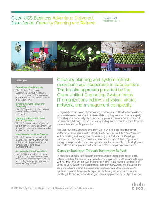
Capacity planning and system refresh Highlightsoperations are inseparable in data centers.optimum approach ties capacity expansion to the regular server refresh cycle,enabling IT to plan for demand and gain computing power in an intelligent manner.addition, built-in management functions provide exceptional visibility into and control over the entire infrastructureto streamline and coordinate administrative effort and eliminate common errors that delay deployment and disrupt operation.that supports blade and rack-mountservers to deliver scalability andperformance. A unified fabric supportedby a single, distributed virtual switchinterconnects all server resources.Servers and virtual machines areinterconnected equally and consistently,eliminating multiple layers of switching.This radically simplified architecturepacks more computing power intoless space while allowing IT to choosefrom a portfolio of servers to delivermassive computing density andcreates barriers to resource sharing and requires additional dedicated servers standing by to take over work in the event of a failure. Cisco UCS eliminates architectural silos through on-demand provisioning. Any computing resource potentially can be used for any application at any time. The infrastructure is “wire once” with all configuration managed through Cisco UCS Manager, eliminating the physical barriers that used to prevent applications from sharing resources.The intelligent infrastructure providedby Cisco UCS enables the entireconfiguration to be programmedthrough the intuitive Cisco UCSManager GUI and open standard XMLAPI. While other vendors supportthe automatic configuration of a fewparameters, Cisco UCS Managerincludes nearly 100 server identityparameters, eliminating the needfor manual tasks or the creationof scripts or the use of tools andagents that further complicate the ITenvironment. With Cisco UCS Manager,IT organizations can plan capacity on aholistic, data center wide basis, sharinginfrastructure across applications andharnessing it to best meet businesspriorities and service-level agreements(SLAs).Eliminating Networkand Cable Sprawl andComplexityUsing traditional implementations, theconnection of servers and storagesystems to growing numbers of userapplications and services requires extensive networking infrastructure. The resulting dramatically increased connectivity uses massive numbersof cables, creating significant management challenges. Administrators find it difficult to locate ports for new servers, to map and zone connectivity, and to track and locate sourcesof failures. In addition, this cable proliferation and sprawl requires vast numbers of switch ports and switches, which consume power and increase management complexity.Simplified Network Infrastructure Addressing the increasing need for better design and control, Cisco UCS provides greater network density with less cabling and complexity. Cisco’s unified fabric integrates Cisco UCS servers with a single high-bandwidth, low-latency network that supportsall system I/O. This fabric carries IP, storage, and management traffic over redundant 10 Gigabit Ethernet and Fibre Channel over Ethernet (FCoE) networks. This approach simplifies the architecture and reduces the number of I/O interfaces, cables, and access-layer switch ports that are required for traditional platforms. This unification can reduce network complexity by up to a factor of three, and the system’s wire-once network infrastructure increases agility and accelerates deployment with zero-touch configuration.All I/O traffic meets at a single specific and redundant point at which it is efficiently and consistently managed, increasing network security, simplifying management, and reducing errors. This approach eliminates blade-server and hypervisor-resident switching, condensing three network layersinto one and reducing capital andoperating costs. With the capability tointerconnect physical servers and virtualmachines as functional equivalents,the architecture delivers outstandingvisibility and control that lets virtualnetworks be managed with the samelevel of control as physical networks.Simplifying and AcceleratingServer Refresh OperationsThe ad hoc approach to expansionused in many data centers makes itdifficult to refresh and consolidate theenvironment. Cumbersome processesthat are tied to a complicated physicaland virtual infrastructure hamper IT’sability to install and configure newsystems and to rehost virtual serversand applications. Administrators mustperform tedious, repetitive, and time-consuming tasks that are often thesource of errors or result in inconsistentconfigurations or application ofcorporate policies and security. Thesedelays and inconsistencies affectapplication and service redeploymentand keep the IT organization fromsupporting real-time business needsand priorities.Automated Configuration for FastDeploymentCisco UCS simplifies and acceleratesserver refresh operations throughautomated configuration. The intelligentinfrastructure abstracts server identity,personality, and I/O connectivityfrom the hardware, enabling thesecharacteristics to be applied ondemand. Every aspect of a server’sconfiguration, from firmware revisionsand BIOS settings to network profiles,can be assigned through the system’sopen, documented, standards-basedXML API or Cisco UCS Manager GUI.As a result, server configurations canbe replicated easily. A new server canappear to the software stack just likethe old server, making server refreshoperations as simple as applying aCisco service profile and rebooting tolaunch the new system.Service Profiles Support PrestagingCisco service profile templatesestablish policy-based configurationfor server, network, and storageresources and can be used to logicallypreconfigure these resources evenbefore they are deployed in the datacenter. By preparing service profiles inadvance, administrators can prestageIP addresses and storage world-widenames (WWNs) and attach mappingsto components. In addition, CiscoUCS blade server slots can be set toautomatically configure blade serversupon insertion with network andstorage settings that are in compliancewith the policies established byappropriate data center administrators.Configuration also can be performed asa manual process as needed, with fullserver identity parameter control andintegration with network and storageresources.Making Virtualization MoreEffectiveAs data centers reach the limits oftheir physical capacity, virtualizationstrategies to consolidate workloadsonto fewer resources can be importantaids. Yet the virtualization effortsdeployed by many data centers haveresulted in new challenges. The useof blade server chassis-resident networks and hypervisor-resident software switches creates a complex set of switching layers that makes managing, debugging, and securing virtual networks difficult. Server sprawl continues unabated, with a proliferation of physical servers added to the environment to support a vast arrayof virtual machines, delivering ever-increasing numbers of applications and services. With a patchworkof technologies in place, physicaland virtual systems are deployed, connected, and managed in many different ways, further complicating infrastructure administration and management.More Virtualization at Less Cost Cisco UCS enables IT organizations to meet ever-increasing guest operating system memory footprint demands on fewer physical servers. The system’s high density, high-performance design,including Cisco Extended MemoryTechnology, increases consolidationratios for 2-socket servers, saving thecapital, operating, physical space, andlicensing costs of running virtualizationsoftware on larger, 4-socket servers.With support for up to 1 terabyte(TB) of high-speed memory in a2-socket server, organizations canhost applications using less-expensiveservers without sacrificing performance.As a result, IT organizations can putmore virtual machines on each server,reducing physical server sprawl andbreaking down management silos.Greater Visibility and ControlIT organizations need to simplifyphysical infrastructure to break downsilos and make the data center moreeffective. They also need to improvetheir virtual infrastructure so that it canbe managed just as simply and easilyas it scales. Traditional virtualizedenvironments require the use ofsoftware-based switches that reside inthe hypervisor. The insertion of a newswitch can cause a loss of visibility fromthe physical network interface to virtualmachines. The result is a network ofvirtual machines with connection pointsthat cannot be seen. If connectionscannot be seen, they cannot bemanaged or secured.Cisco UCS uses virtualization-optimizednetworking that makes managingvirtual machine networks equivalentto managing physical networks.Cisco FEX Technology architectureextends the visibility of network andstorage access all the way to individualvirtual machines, without hypervisorintervention. These connectionsterminate in the fabric interconnects asvirtual ports that are managed exactlythe same way as physical ports. VirtualDistributed Virtual Blade Chassis+=+Servers Fabric Interconnects Fabric ExtendersFigure 2. Cisco UCS Combines Blade and Rack Servers, Networking, and Storage Resources in a Distributed, Virtual Blade Chassis with a Single, Redundant Point of Connectivity and ManagementAmericas Headquarters Cisco Systems, Inc. San Jose, CA Asia Pacific Headquarters Cisco Systems (USA) Pte. Ltd. Singapore Europe HeadquartersCisco Systems International BV Amsterdam, The NetherlandsCisco has more than 200 offices worldwide. Addresses, phone numbers, and fax numbers are listed on the Cisco Website at /go/offices .Cisco and the Cisco logo are trademarks or registered trademarks of Cisco and/or its affiliates in the U.S. and other countries. To view a list of Cisco trademarks, go to this network interface cards (vNICs) are attached to virtual machines, and their network profiles remain constant and attached, even when virtual machines are moved from one physical server to a different server, enhancing mobility and security. Workloads can bemigrated between physical devices, optimizing performance and maintaining security protocols and policies, without requiring intervention by the network team to reset quality of service (QoS) and security for each migrated virtual machine.The Cisco UCS design results in a distributed, virtual blade chassis that combines the performance and management of physical networks with the scalability of virtual networks. Administrators can use familiar management models on virtualmachines and take advantage of built-in automation and intelligence to gain outstanding visibility into, and control over, virtualized environments. Forexample, bandwidth can be flexibly and dynamically managed with a QoS policy to help guarantee bandwidth for priority workloads running in virtual machines, while also helping ensure that overall bandwidth is used efficiently and not wasted (Figure 2).More Capacity and Reduced ComplexityData center infrastructure management has become a complicated challenge. The proliferation of management points and the physical devices to which they are connected has resulted in a new kind of sprawl that must be contained. Typically, administrators have to use a variety of element managers to interact with dozens of management touch points that are distributedacross multiple servers, blade chassis, racks, networking, and storageresources. Unfortunately, most vendors attempt to solve this management challenge by introducing additional layers of management tools that are patched together into an accidental architecture that creates more work for administrators.Less Complex and Easier to Manage The unified infrastructure andarchitecture-by-design approach of Cisco UCS delivers the scalability needed to perform capacity planning and refresh activities without the complexity of traditional systems. The dramatic reduction in the number of physical components results in a system that makes effective use of limited space, power, and cooling by deploying less infrastructure to perform the same, or even more, work.The system’s unified fabric results in fewer NICs, host bus adapters (HBAs), cables, and upstream switch ports, and eliminates the need for a parallel Fibre Channel end-to-end network. Traditional blade server chassis resident switches are replaced by a low-cost, low-power, zero-management fabric extender that enables the entire system to scale across multiple blade chassis and rack servers without addingmanagement points. All hardware and software components are managed through the unified, embedded Cisco UCS Manager to improve operation efficiency with seamless scaling.ConclusionDeployment of Cisco UCS systems enables data centers to reap the benefits of a simplified infrastructure. By consolidating from a large-footprint rack or complex and network-intensive blade environment to Cisco UCS, IT organizations can reduce the footprint and complexity of the entire datacenter. Server refresh and consolidationoperations become easy, scalable, and repeatable exercises that optimize data center investments.Learn MoreTo learn more about Cisco UCS, visit /go/ucs or contact your local account representative.。
思科认证辅导给你的路由器安装系统

思科认证辅导给你的路由器安装系统Cisco路由器IOS映像恢复及升级方法由于历史原因,Cisco公司的路由器产品丰富且繁杂,Cisco路由器的专用操作系统IOS 映像也同时存在多个版本,以下就分别针对两类加载不同版本的IOS映像文件的Cisco路由器做讨论。
一、Cisco 1000,1600,2500,4000系列1、IOS映像恢复的方法及步骤1)连接PC的COM1口与路由器的console口,使用PC的超级终端软件访问该路由器;2)开启路由器的电源开关,并在30秒内按下键盘的Ctrl+break,中断路由器的正常启动以进入rom监视模式,屏幕上提示符如下:>3)键入如下命令:>o /r 0x2101改变路由器虚拟寄存器的默认值(0x2102);4)键入重启命令:>i路由器重启,当屏幕显示以下信息表明路由器重启完毕:System Bootstrap,Version 5.2(8a),RELEASE SOFTWARECopyright(c)1986-1995 by cisco Systems2500 processor with 1024 Kbytes of main memory…Press RETURN to get started!5)路由器在虚拟寄存器的值为0x2101时自动进入rom启动模式:router(boot)>6)此时,将TFTP服务器上的IOS映像文件恢复至路由器flash memory中,依次键入以下命令:router(boot)>enrouter(boot)#copy tftp flashSystem flash directory:No files in System flash[0 bytes used,4194304 available,4194304 total] Address or name of remote host [255.255.255.255]?192.168.18.168(IP 地址已作技术处理,下同)Source file name?igs-i-l.110-22a.bin(IOS映像文件名)Destination file name [igs-i-l.110-22a.bin]?Accessing file 'igs-i-l.110-22a.bin' on 192.168.18.168……Loading igs-i-l.110-22a.bin from 192.168.18.168 (via Ethernet0):![OK]Device needs erasure before copying new fileErase flash device before writing?[confirm] Copy 'igs-i-l.110-22a.bin' from server as 'igs-i-l.110-22a.bin' into Flash WITH erase?[yes/no]yErasing device……eeeeeeeeeeeeeeee……erasedLoading igs-i-l.110-22a.bin from 192.168.18.168 (via Ethernet0):(!表示恢复成功)7)还原路由器虚拟寄存器的默认值(0x2102),恢复路由器的正常启动顺序,依次键入以下命令:router(boot)#conf trouter(boot)(config)#config-register 0x2102router(boot)(config)#exitrouter(boot)#wrrouter(boot)#reload2、IOS映像升级的方法及步骤1)升级之前先备份,将相关文件备份至TFTP服务器,键入如下命令:router#copy bootflash tftp(Cisco 2500系列路由器不存在bootflash,相应的是rom)router#copy flash tftprouter#copy startup-config tftp2)因为Cisco 1000,1600,2500,4000系列路由器不允许在正常工作状态下重写flash memory,所以只有进入rom(或bootflash)启动模式才能升级IOS映像,依次键入以下命令:router#conf trouter(config)#config-register 0x2101router(config)#exitrouter#wrrouter#reload3)路由器重启完毕后进入rom(或bootflash)启动模式,从TFTP服务器将新的IOS 映像文件拷贝至路由器的flash memory中:router(boot)#copy tftp flash4)还原路由器虚拟寄存器的默认值(0x2102),恢复路由器的正常启动顺序,依次键入以下命令:router(boot)#conf trouter(boot)(config)#config-register 0x2102router(boot)(config)#exitrouter(boot)#wrrouter(boot)#reload二、Cisco 1700,2600,3600,7200系列1、IOS映像恢复的方法及步骤1)连接PC的COM1口与路由器的console口,使用PC的超级终端软件访问该路由器;2)开启路由器的电源开关,并在30秒内按下键盘的Ctrl+break,中断路由器的正常启动以进入rom监视模式,屏幕上提示符如下:rommon 1>3)键入xmodem命令:rommon 1>xmodem c3640-i-mz.120-10.bin(IOS映像文件名)4)然后,路由器一直等待从PC上接收该IOS映像文件,此时在超级终端软件中点击发送选项,选择存放在PC本地硬盘中的IOS映像文件,确定后即开始下载文件至路由器的flash memory中,由于通讯带宽只有9600波特,整个文件下载时间约为1.5小时(依文件大小而定),屏幕显示信息如下:Do not start the sending program yet……device does not contain a valid magic numberdir:cannot open device flash:W ARNING:All existing data in flash will be lost!Invoke this application only for disaster recovery. Do you wish to continue?y/n[n]:yReady to receive file c3640-i-mz.120-10.bin ……Erasing flash at 0x307c0000program flash location 0x30380000Download Complete!program load complete,entry point:0x80008000,size:0x38f410 5)接着,路由器将自动重启,屏幕显示信息如下:Self decompressing the image:################################# [OK]…Press RETURN to get started!2、IOS映像升级的方法及步骤1)同理,升级之前先备份,将关键文件备份至TFTP服务器,键入下列命令:router#copy bootflash tftp(Cisco 3600系列路由器不存在bootflash)router#copy flash tftprouter#copy startup-config tftp2)因为Cisco 1700,2600,3600,7200系列路由器允许在正常工作状态下重写flash memory,所以直接键入以下命令就可完成IOS映像的在线升级:router#copy tftp flashrouter#reload或者,为保险起见(以路由器停止服务为代价),在进入rom监视模式后才进行IOS映像的升级,则依次进行下列操作:2)在路由器重启加电后30秒内按下键盘的Ctrl+break,中断路由器的正常启动直接进入rom监视模式,屏幕上提示符如下:rommon 1>或者,在路由器重启过程完成后进行以下操作,同样可以进入路由器的rom监视模式:router#conf trouter(config)#config-register 0x0router(config)#exitrouter#wrrouter#reloadrommon 1>3)键入以下命令,将IOS映像的升级文件从TFTP服务器复制至路由器的flash memory 中:rommon 1>b c3640-i-mz.121-2.T 192.168.18.168 program load complete,entry point:0x80008000,size:0x4ed478Self decompressing the image:##################################[OK]Loading c3640-i-mz.121-2.T from 192.168.18.168 (via Ethernet0/0):[OK - 5166484/10332160 bytes]4)还原路由器虚拟寄存器的默认值(0x2102),恢复路由器的正常启动顺序,依次键入以下命令:rommon 1>confreg 0x21025)键入重启命令,使得新配置生效,完成IOS映像的离线升级:rommon 2>reset。
UCS系统实施手册
U C S系统实施手册(总21页) -CAL-FENGHAI.-(YICAI)-Company One1-CAL-本页仅作为文档封面,使用请直接删除UCS系统实施手册目录1.背景介绍 (4)2.Cisco统一计算系统部署过程 (6)2.1.UCS部署端口连接与IP地址分配 (6)2.2.Fabric interconnect初始配置 (6)2.3.UCSM管理界面登录 (7)2.4.端口属性设置 (8)2.5.建立Service Profile (10)直接创建单个Service Profile (10)设置Profile名称及UUID (11)设置存储属性 (11)设置网卡属性 (12)设置设备启动顺序 (13)关联Service Profile与刀片 (14)从template中生成Service Profile (15)配置MAC Pool (15)创建 VLAN (17)创建Service Profile模板 (17)设置存储属性 (19)设置网卡属性 (20)创建服务配置文件并关联到刀片服务器 (21)1.背景介绍本文旨在介绍思科统一计算系统的核心特性能够如何简化服务器,网络以及虚拟环境的部署、增强管理、提供出色性能和安全性。
文章中介绍了该系统的统一阵列、统一内嵌管理、服务配置文件。
本文也介绍了如何配置统一阵列,如何产生和配置service profile,以及如何利用service profile快速配置服务器,同时也介绍如何实现高可用配置。
服务器虚拟化为世界各地的数据中心带来了众多优势,但同时它也向数据中心提出了挑战。
如果有统一的I/O配置和足够的带宽,在每台物理服务器上支持大量VM,则资源池的管理会较为容易。
资源池将能更快速地应对迅速变化的业务情况和工作负载,新服务器资源的添加能在几分钟内完成,然后设置并投入使用。
而无需通过数小时甚或数天繁琐、耗时且易于出错的人工配置,来准备服务器及其接口、固件和设置。
CISCO_设备安装与调试
Cisco 设备安装与调试一、PIX 515防火墙介绍也应用Cisco Secure PIX防火墙系列通过其业界领先的性能和端到端安全服务的有机组合,确立了Cisco在独立防火墙市场上的领先地位。
Cisco Secure PIX防火墙系列通过其业界领先的性能(参见Key实验室给出的Firebech测试结果)和Cisco端到端安全服务的有机组合,确立了在独立防火墙市场龙头老大的地位。
集成硬件/软件Cisco Secure PIX防火墙系列提供了很高的安全性,能够满足客户的所有需求,但不会影响客户网络的性能。
虽然PIX 520是高端外围安全产品当之无愧的领导者,但随着虚拟专网(VPN)的出现和越来越多的中小公司进入Internet市场,防火墙市场的需求越来越大。
目前,各组织机构需要价格合理且功能强大的防火墙,为全球化的VPN、地区性分支机构和那些希望以预算内的价格实现安全性的中小公司提供必要的安全手段。
PIX 515正是为了满足以上需求而设计。
现在,利用PIX v5.0软件以及所有的后续v5.x版本,所有的设备包括PIX515-R和PIX515-UR都完全支持IPSec。
这类版本使PIX可以在两个PIX、一个PIX和任意Cisco VPN路由器、一个PIX和Cisco安全VPN客户机之间创建和端接VPN隧道。
PIX-515:无限软件捆绑具有无限软件许可证的PIX 515-R是为那些正在寻求使用基本防火墙功能来实现高性能安全性的企业而提供的入门级Cisco解决方案。
它所提供的能力可以处理50000余个同时连接,吞吐量高达170Mbps。
支持多达3个以太网接口的PIX 515-R-BUN是一种具有特别高效费比的解决方案,特别适合那些选择在防火墙之外托管自己的网站或者通过Internet服务提供商(ISP)托管网站,并且需要较合理性价比防火墙解决方案的小型公司。
另外,也非常适合那些仅需要与自己企业网进行双向通信的远程站点,或由企业网在自己的企业防火墙上提供所有的Web服务的情况。
CISCO产品配置手册6

参考Cisco路由器口令恢复当Cisco路由器的口令被错误修改或忘记时1. 开机时按<Ctrl+Break>使进入1600系列boot#set ios-conf=0x2142Cisco800系列正常值为0x21023. 重新启动路由器4. 在模式5 255.255.248.0 30 28466 255.255.252.0 62 18227 255.255.254.0 126 5188 255.255.255.0 254 2549 255.255.255.128 518 12610 255.255.255.192 1822 6211 255.255.255.224 2846 3012 255.255.255.240 4894 1413 255.255.255.248 8198 614 255.255.255.252 16382 2C类地址2 255.255.255.192 2 623 255.255.255.224 6 304 255.255.255.240 14 145 255.255.255.248 30 66 255.255.255.252 62 2三任务 命令 copy flash: tftp 将系统软件备份到TFTP服务器 copy tftp flash: 将TFTP服务器中的系统软件下载到路由器中 TFTP软件可以从cisco公司网站或思科网络加油网站上下载此软件可在Windows 95/98/2000及NT 上安装并通过菜单设置Root目录为新系统文件所在目录设置PC机IP地址与路由器以太网口 IP地址在相同网段 假设计算机的IP地址为a.a.a.a假设IOS文件放在C:\ios子目录下参考在这台计算机上运行TFTP SERVER软件switch>enable switch# configure t switch(config)# interface VLAN1 switch(config-if)# ip address IP地址 掩码 switch(config-if)#^z switch# write memory ping 主机地址应能ping通 查看当前的系统文件 switch# dir Directory of flash:/ 2 -rwx xxx Mar 01 1993 00:15:41 info 3 -rwx xxxxx Dec 10 1999 19:12:29 c2900XL-diag-mz-112.8-SA2 4 drwx xxxxx Mar 01 1993 00:17:43 html 179 -rwx xxxx Mar 01 1993 00:02:46 config.text 6 -rwx xxxx Jan 01 1970 00:36:10 c2900XL-h-mz-112.8-SA2 230 -rwx xxx Mar 01 1993 00:17:43 info.ver 231 -rwx xxx Jan 01 1970 00:42:00 env_vars 其中c2900XL-h-mz-112.8-SA2就是系统文件接着使用delete命令将其删除 switch# delete flash:c2900XL-h-mz-112.8-SA2 还要将html目录中的文件删除 switch# delete flash:/html/*.* switch# delete flash:/html/Snmp/*.* 你需要按回车键来确认每个文件的删除 将新的系统软件传送到flash中 switch# tar /x tftp://tftp_server_ip_address/c2900XL-hs-mz-112. 8-SA5.tar flash: Loading /path/filename.tar from server_ip_address (via!) extracting c2900XL-hs-mz-112.8-SA5.bin (xxxxxx bytes) !!!!!!!!!!!!!!!!!!!!!!!!!!!!!!!!!!!!!!!!!!!!!!!!!!!!!!!!!!!!!!!!!!!!!!!!!!!!!!!!!!!!!!!!!!!!!!!!!!!!!!!!!!!!!!!!!!!!!!!!!!!!!!!!!!!!!!!!!!!!! extracting advanced.gif (2648 bytes) extracting amber.gif (530 bytes)! extracting bar.gif (4156 bytes)! extracting cool.gif (530 bytes) extracting daytona.gif (1470 bytes) extracting duplgnd.gif (639 bytes)! . . . 指定启动时使用的系统文件名 switch#config terminal switch(config)# boot system flash: c2900XL-hs-mz-112.8-SA5.bin switch(config)# ^z 重启交换机可用xmodem协议将系统文件送入交换机 switch: copy xmodem: flash:c2900XL-c3h2s-mz-120.5-XP.binBegin the Xmodem or Xmodem-1K transfer now... CCC...................................................................................................................................................... .............................................................................................................................................................. ........................................................................File "xmodem:" successfully copied to "flash:c2900XL-c3h2s-mz-120.5-XP.bin"switch: flash:c2900XL-c3h2s-mz-120.5-XP.bin3. 在rom monitor状态升级2600系列路由器如果因非正常原因导致2600系列路由器的IOS丢失rommon 1 > IP_ADDRESS=172.15.19.11 rommon 2 > IP_SUBNET_MASK=255.255.255.0 rommon 3 > DEFAULT_GATEWAY=172.16.19.1 rommon 4 > TFTP_SERVER=172.15.20.10 (存放IOS文件的主机名) rommon 5 > TFTP_FILE=c2600-i-mz (IOS文件名) rommon 6 > tftpdnld IP_ADDRESS=172.15.19.11 IP_SUBNET_MASK=255.255.255.0 DEFAULT_GATEWAY=172.16.19.1 TFTP_SERVER=172.15.20.10 TFTP_FILE=2600-i-mz Invoke this command for disaster recovery only. WARNING: all existing data in all partitions on flash will be lost! Do you wish to continue? y/n: [n]: 键入 y 开始下载IOS 软件. 四 解答但是需要注意的是支持这两种接口卡的网络模块如下所示 NM-2FE2W NM-2W如下所示NM-2E2W 2. Cisco3600系列路由器的NM−4A/S解答也能够支持同步最大同步速率均为128Kbps解答 DB60转V35或RS232 如 WIC-2T 449等电缆 CAB-SS-V35-MT CE1有什么区别 Cisco 7000上的ME1可配置为E1而Cisco 2600/3600上的E1Cisco 2600系列路由器对IOS软件有何需求Cisco2600系列路由器中并且如果支持VLAN间路由5. Cisco3660路由器与3620/3640路由器相比在硬件上有那些不同 不同点如下而Cisco3620/3640基本配置中不包括以太网接口而 Cisco3620/3640不支持网络模块热插拔 而Cisco3620/3640的冗余电源为外置的解答ÈçºÎÑ¡ÓÃÄ¿Ç°´æÔÚµÄÁ½ÖÖ½»»»Ä£¿é(²úÆ·±àºÅÈçÏÂ)这两个模块的使用环境不同 • WS-X4306-GB 是一个6口的千兆交换模块适合做网络的主干也可以与具有千兆网卡的服务器相连其中有两个口是独占千兆的带宽另外16个口共享8G的全双工的带宽此模块适合在服务器比较集中的地方连接千兆的服务器 3. 关于堆叠技术Catalyst 3500XL/2900XL的堆叠是如何实现的a. 需要使用专门的堆叠电缆b. 可以选用2种堆叠方法c. 2种方法都可以做备份点对点法最多可支持8台Catalyst 3500 XL系列交换机做堆叠时 解答菊花链方式和点到点方式堆叠的交换机依次连接• 当使用点到点方式时 其余的交换机通过堆叠GBIC卡和堆叠线缆与3508G相连两种方法分别见图1 图1点到点连接方式 这两种方法都分别支持堆叠的冗余连接冗余连接是通过将最上面的交换机与最下面的交换机用堆叠线缆相连接完成的是通过使用第2台3508交换机来完成的 图3 3.3 另外一个千兆口是否可以连接千兆的交换机或千兆的服务器可以 4. 关于集群技术 4.1 能够支持Cluster技术的产品目前主要有哪几种名称 软件版本要求 交换机类别 Catalyst 1900/2820 9.00.00及以上系列(A, EN) 如何使用• 可以应用在交换机之间交换机和服务器之间 • 可以将2个或4个10/100Mbps或1000Mbps端口使用 Ethernet Channel Tech.4G(1000Mbps端口) 或800M(10/100Mbps端口) 5.2 解 答 负载均衡当端口设置成 Ethernet Channel时 解 答 决定从哪条链路输出以决定链路的输出Ethernet Channel Technology 与 PAgP (Port Aggregation Protocol ) 的区别解 答 它支持在 Ethernet Channel 上的 Spanning Tree Protocol和Uplink Fast6. Cisco Catalyst系列千兆交換机上的 SX解答解答和 300米(中間有1个中繼器)但在實際使用百兆模塊經常用來傳輸距离在1-2公里左右的多模光纖或距离在30-40公里左右的单模光纤上的數据流量其传输速率已經達不到百兆解答这是因为该模块虽然可以实现第三层的功能因此它只能在内部网(Intranet)中实现第三层交换功能9. Catalyst 5000上WS-X5012与WS-X5012A (48 端口 Ethernet switchingmodule) 有什么区别?解答:WS-X5012A是WS-X5012为降低生产成本而形成的改进版,两者功能相同,价格相同。
- 1、下载文档前请自行甄别文档内容的完整性,平台不提供额外的编辑、内容补充、找答案等附加服务。
- 2、"仅部分预览"的文档,不可在线预览部分如存在完整性等问题,可反馈申请退款(可完整预览的文档不适用该条件!)。
- 3、如文档侵犯您的权益,请联系客服反馈,我们会尽快为您处理(人工客服工作时间:9:00-18:30)。
UCS C210安装windows2003指南
一、名词解释
UCS即Cisco Unified Computing System,思科的数据存储系统。
二、准备工作
1、随设备带的DVD光盘驱动
2、Windows2003安装光盘或者IOS镜像
3、将UCS的管理网卡连接到有DHCP Server网络
4、给UCS连接上显示器、键盘、鼠标
三、登录到CIMC
CIMC即Cisco Integrated Management Controller (CIMC) utility,是思科UCS的管理界面。
启动服务器后,在显示器上可以看到CIMC信息,如图:
在IE浏览器输入在显示器上看到的IP地址,进入登录界面
输入账号密码登录,默认账号为admin,默认密码为password。
四、CIMC中的操作
CIMC界面如下:
在CIMC中我们可以看到UCS型号,Serial Number,Server Status,CPU频率,内存容量,风扇,电源状态等众多信息,我们可以修改UCS的启动顺序,修改管理网卡的IP地址,启动/关闭/软重启/硬重启服务器,登
录KVM控制台等众多操作。
五、配置raid
1、ctrl + H 进入raid配置界面
2、选择配置向导–>新建配置-> 下一步
3、自定义配置
4、添加磁盘到磁盘组
5、确认
6、下一步
7、添加SPAN
8、选择raid 级别,选择磁盘容量。
9、确认raid5 容量
10、下一步
11、确认
12、完成
六、登录KVM控制台
在登录KVM控制台之前,请先在PC上安装有JRE(java运行环境),然后在CIMC中点击Launch KVM Console,弹出窗口提示该Web站点的证书无法验证,点击“是”继续,如图
等待几秒钟后,系统会弹出一个Cisco Virtual KVM Console窗口,在这个窗口下,我们可以像控制自己电脑一样控制UCS,如图:
七、虚拟光驱及软驱
从Virtual KVM Console窗口我们可以将电脑上的文件、光驱虚拟成UCS的软驱、光驱,不过开始之前应该要先做一个准备工作。
6.1开启Virtual Media
在将管理PC上的文件、光驱虚拟成UCS的软盘、光驱之前,需要开
启Virtual Media,否则就会弹出以下错误。
系统告知我们虚拟媒体不可映射,要解决这个问题,操作如下:
回到UCS的CIMC界面,点击server标签下的Remote presence,在右边的界面中点击Virtual Media,界面如下:
将Virtual Media Properties下面的Enabled后边的复选框勾上,并点击右下边的Save Changes保存。
如图
6.2将管理PC的光驱虚拟为UCS的光驱
点击Tools——>Launch Virtual Media,如图
弹出如下窗口
在弹出的窗口中,我们将光驱盘符前的Mapped前打上勾就能将管理PC的光驱虚拟成UCS的光驱。
6.3将管理PC的光驱虚拟为UCS的光驱
如果需要使用ISO镜像安装操作系统,则需要将操作系统的ISO镜像虚拟成UCS的光驱,操作如下
点击Tools——>Launch Virtual Media,如图
在弹出的窗口中点击Add Image,选择windows2003安装镜像,如图添加完成后如图
将ISO镜像文件前边复选框打勾完成映射
这样就完成了将管理PC上的ISO镜像虚拟成UCS的光驱。
6.4将管理PC的文件虚拟为UCS的软驱
UCS的硬盘windows2003一般不能识别,在安装操作系统时需要安装硬盘驱动。
操作如下
点击Tools——>Launch Virtual Media,在弹出的对话框中点击Add Image,选择UCS硬盘驱动。
注意:UCSraid卡驱动的位置一般在
\Windows\Storage\LSI\9261\W2K3\x86\9261E_W2K3_x86.img。
将驱动前边的Mapped复选框勾上,就成功的将PC上的文件虚拟成软驱了。
八、更改启动顺序
回到Virtual console窗口,点击Macros——>Ctrl-Alt-Del重启UCS
等系统重启到如下界面时
根据提示按F2进入BIOS,如图
按方向键移动到Boot Options标签,按方向键移动到Floppy Order选项,按回车,如图
在Boot Option #1选项上,按回车键,如图
移动到Cisco Virtual Floppy 1.20,按回车键,将软盘第一启动方式改为Virtual Floppy。
修改后的界面如下:
按ESC回到BIOS的主界面,如图
如果是用ISO镜像安装操作系统,就需要将CMROM order的启动顺序修改为Virtual CDROM为第一启动顺序,修改方式与软盘启动顺序的修改方式一样。
修改后如图,表示Virtual CDROM优先于物理CDROM启动
移动到Boot Option #1,选择第一启动顺序为操作系统安装盘所在的位
置,物理光驱为SATA5:HL-DT-STDVDRAM 虚拟光驱则为Cisco Virtual CDROM
将第二启动方式修改为软驱启动方式,如图
按F10保存并退出,UCS将自动重启。
九、安装操作系统
UCS启动过程中,UCS将先显示CIMC界面,然后根据启动顺序进入windows2003的安装界面,根据提示按F6给UCS的硬盘安装驱动程序。
注意:该提示显示时间很短,建议刚进入windows2003的安装界面后就一直按着F6,直到系统提示指定硬盘驱动程序的位置。
等待一段时间后,进入硬盘驱动程序安装界面,如图
根据提示按“S”键指定驱动程序的位置,如果前边虚拟软盘成功,将显示如下:
按Enter继续
这里将返回到指定硬盘驱动程序界面,如图
界面与指定驱动程序前一样,不要怀疑,按Enter继续,安装程序继续,直到如下界面
按Enter继续
同意微软的条款按F8进入如下界面
安装到所需的分区,点击下一步,安装大约需要40分钟。