FLUKE187、189真有效值多用表校准手册(中文版)
(完整版)数字多用表直流电压表测量审核不确定度评定

数字多用表直流电压、交流电压、直流电阻测量结果的不确定度评定一、直流电压测量不确定度的评定1 概述1.1测量依据: JJF 1587-2016 数字多用表校准规范。
1.2测量环境条件: 环境温度20℃,相对温度60%。
1.3测量标准: 多功能标准源HG6501。
1.4 被测对象: 数字多用表FLUKE187,直流电压示值误差。
1.5 测量方法: 采用直接测量法,将多功能标准源HG6501电压输出端与数字多用表输入端连接直接测量。
将数字多用表电压示值与多功能标准源HG6501参考值相减,其差值即为数字多用表直流电压的示值误差。
2 数学模型n x V V -=∆式中: ∆—示值的绝对误差;x V —数字多用表FLUKE187示值; n V —多功能标准源HG6501参考值;3 不确定度传播律)()()(2222212n x c R u c R u c u +=∆ 灵敏系数 11=∂∆∂=x R c ,12-=∂∆∂=nR c 4 测量不确定度来源分析与标准不确定度分量的评定不确定度来源主要为被测仪器的测量重复性、所用标准器的误差、分辨力以及环境条件的影响等。
因校准时按照规范要求的环境条件进行,故其引入的不确定度分量可以忽略不计。
4.1多功能标准源HG6501引入的标准不确定度分量u 1:由多功能标准源HG6501技术指标得知,直流电压100mV 绝对不确定度为:读数×0.02%+0.02mV (k =2),因此校准100mV 时绝对不确定度为100mV ×0.02%+0.02mV =0.04 mV ,则标准不确定度u 1=0.023mV 同理可求得其它校准点引入的标准不确定度结果如下表:4.2被校数字多用表分辨力引入的标准不确定度分量u2:数字多用表FLUKE187在示值(100mV)时的分辨力为0.01mV, 半宽a=0. 005mV, 在区间可以认为服从均匀分布,包含因子k=3,则u2= 0. 005mV /3=0.0029 mV 同理可求得其它校准点分辨力引入的标准不确定度结果如下表:4.3被测仪器测量重复性引入的标准不确定度分量u A按照重复性测量要求对直流电压100mV点进行连续10次测量,结果如下表:主要来源是由数字多用表的测量重复性引起的。
福禄克187万用表维修手册_主板关键测试点说明书
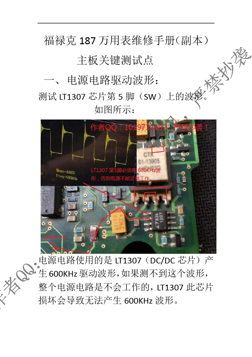
福禄克187万用表维修手册(副本)主板关键测试点一、电源电路驱动波形:测试LT1307芯片第5脚(SW)上的波形。
如图所示:电源电路使用的是LT1307(DC/DC芯片)产生600KHz驱动波形,如果测不到这个波形,整个电源电路是不会工作的,LT1307此芯片损坏会导致无法产生600KHz波形。
二、主时钟驱动波形。
测试7.37MHz晶振两端波形,为7.3M正弦波,如果这个晶振损坏或者没有波形,则整机无法正常工作(此晶振是给FLUKE2000单片机芯片提供时钟信号)。
93C56(EEPROM芯片)供电电压来自钽电容的3V供电。
提示:以上所有测试点都是以电源负极为参考点测量的电压和波形。
三、显示驱动芯片时钟波形。
FLUKE1998是LCD液晶屏驱动芯片,此芯片旁边有一颗32.768KHz的实时时钟晶振,此晶振波形为32K正弦波。
此32.768KHz实时时钟晶振如果损坏,会导致显示不正常,(FLUKE1998)液晶屏驱动芯片本身损坏也会导致显示不正常。
四、(主控芯片)/液晶屏驱动芯片供电电压。
FLUKE1998是液晶屏驱动芯片。
FLUKE2000是主控芯片(MCU)。
FLUKE1998(液晶屏驱动芯片)的供电是(TPS77030)LDO芯片输出的3.3V经过管子转换为3.09V左右的供电提供给液晶屏驱动芯片供电。
FLUKE2000(主控芯片)的供电来自电源电路中的钽电容产生的3.11V提供给主控芯片供电。
测试点如果图所示:↓五、模拟芯片(FLUKE669918)供电和基准电压。
FLUKE669918(模拟芯片),此芯片内部集成了:A/D转换,真有效值(RMS)模块,功能测量都是这个芯片完成的。
FLUKE669918芯片的供电电压来自TPS77001(LDO)芯片输出的5V供电。
LMC6042双运算放大器的供电电压也来自TPS77001输出的5V 供电。
REF43G是电压基准芯片,该芯片的6脚输出2.5V基准电压提供给FLUKE669918芯片内部的A/D转换电路基准电压。
FLUKE 189的事件记录功能
!"#$%&'(!")*"+, !"#$%!"&!" OL !"#$%&'()*(+ ! !"#$%& 2
#$%&'()
!"#$%&'()* !"#$%& !"#$% MEM !"#$%&!'() 001 !"#$%& !"#$% CANCEL Hz SHIFT !" ! SHIFT LOGGING ! REL
!"#$
!"
!"#
3
72
4320
!"
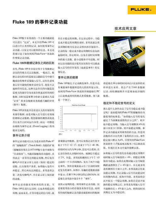
!"#$%&'( !"#$%& 00:00 !" 4320 288 !"# !" 72 $ !" =15
!"#$%&'()*+,!"#$ !" 15 !"#! 995 !"#$%&' !"#$%&' !"# !"#$ 288 &'()* $ 707 !
!"#$%&'()*#$+ !"#$%&'()*+ 1 !"#$%&'()*+,-. !"
!"#$%&'()*+ !"#$%&'()!*
!"#$%&'()* !"#$ 002 !"#$ !" !" !"#$
福禄克 Fluke 287真有效值电子记录万用表 安全须知 说明书

287/289 True-rms Digital Multimeters安全须知访问以注册您的产品并获取更多信息。
警告表示可能对用户造成危险的状况和操作。
XW警告为了防止可能发生的触电、火灾或人身伤害:•使用仪表前请先阅读“安全须知”。
•必须按照本手册的规定使用仪表,否则仪表提供的保护措施可能会失效。
•切勿使用已损坏的仪表。
使用仪表之前,请检查仪表的外壳,检查是否存在裂纹或塑胶缺损。
特别注意接头周围的绝缘。
•使用仪表之前,请确定电池盖已经闭合并且扣紧。
•打开电池盖之前,请先取下仪表上的测试导线。
•检查测试导线的绝缘是否损坏或导线金属是否裸露在外。
检查测试导线是否导通。
若导线有损坏,请更换以后再使用仪表。
•在端子间或任何一个端子与接地点之间施加的电压不能超过仪表上标示的额定值。
•在外盖取下或机壳打开时,请勿使用仪表。
•对 30 V 交流(有效值)、42 V 交流(峰值)或 60 V直流以上的电压,应格外小心。
这些电压有电击危险。
•必须使用本手册指定的替换保险丝。
•测量时,必须使用正确的端子、功能档和量程档。
•不要单独工作。
•测量电流时,应先切断电路的电源,再把仪表连接到电路上。
记住:仪表必须和电路串联。
•在进行电气连接时,先连接公用测试导线,然后再连接带电测试导线;拆线时,先拆除带电测试导线,然后再拆除公用测试导线。
•若仪表工作失常,请勿使用。
产品的保护功能可能受损。
若有疑问,应将仪表送修。
PN 4271782 (Simplified Chinese)August 2012 Rev. 1, 1/18© 2012-2018 Fluke Corporation. All rights reserved.All product names are trademarks of their respective companies. Specifications are subject to change without notice.•切勿在有爆炸性的气体、蒸汽或灰尘附近使用仪表。
福禄克 Fluke 177C真有效值数字万用表 数据表

技术资料FLUKE 170 系列真有效值万用表非常容易使用、坚固耐用且十分可靠如果您的工作离不开您的量表,那么 Fluke 175、 177 和 179 一定是您开展日常工作的完美之选通过真有效值测量提高精度在测量复杂的交流信号时获得精确的电压和电流读数 容易理解不断变化的信号通过模拟柱状图可以很容易地查看波动信号的变化 趋势只需轻动指尖即可测量温度(仅限 179)内置温度计,无需另外携带仪表便可获取温度读数Fluke 170 系列数字万用表是用于电气和电子系统的行业标准故障排除工具Fluke 170 系列数字万用表是为全球专业技术人员提供的理想解决方案。
它们具有对电气和电子系统进行故障排除和维修所需的众多功能,而且它们具有福禄克产品的坚固性、可靠性和精确度。
所有的 170 系列数字万用表都具有真有效值响应能力。
在如今充满谐波和变速驱动器的电气环境中,这些数字万用表能够为复杂的、非正弦曲线信号提供精确的交流电压和电流读数。
福禄克开创性地在数字万用表中引入了模拟柱状图,今天它依然是行业的标准。
对于随时间变化的信号,柱状图比不断变化的数字更容易理解。
Fluke 170 系列数字万用表在满足限制条件的前提下全部享有终身保修。
如果您的工作离不开您的测量工具,那么请确保在您的腰带上挂上一部 Fluke 170 系列数字万用表。
HOLD/AutoHOLDBacklightFunction dialSecondary function °C/°F selection (179 only)Manual/autorange Analog bar graph6000 count digital display 400 mA, 10 A current,with fused inputMIN/MAX/AVG1 所有交流电压和交流电流的量程指定为从量程的 5 % 至量程的 100 %。
2 波峰系数 ≤3(满量程,不超过 500 V ),线性降低至波峰系数 ≤1.5(1000 V )。
数字万用表FLUKE187+189 原始记录 数据选点

5
100.5 2.5 5 1 10交流电压: 量程(mV) 50
500
3000 量程(V) 5
50
500
1000 交流频率:50Hz
标准值(mV) 5 25 50 50 250 500 300 1500 3000 标准值(V) 0.5 2.5 5 5 25 50 50 100 250 400 500 100 500 1000
500
3000
量程(V) 5
50
500
1000
直流电阻: 量程(Ω) 500 量程(kΩ) 5
50
标准值(Ω) 50 250 500 标准值(kΩ) 0.5 2.5 5 5 25 50 50
显示值(Ω)
显示值(kΩ)
500
量程(MΩ) 5
32
50
100
500
100 150 200 250 300 350 400 450 500 标准值(MΩ) 0.5 2.5 5 3.2 16 32 5 25 50 10 50 100 50 250 500
5 5 50 50 500 100 1000
量程(mV) 50 500 3000 量程(V) 5 50
标准值(mV) 5 50 50 500 300 3000 标准值(V) 0.5 5 5 50
显示值(mV) 交流频率:20kHz 交流频率:100kHz
福禄克 Fluke a3000 FC 系列无线万用表 校准手册 说明书

a3000 FCWireless AC ClampCalibration Manual July 2014 Rev. 1, 5/17© 2014-2017 Fluke Corporation. All rights reserved. Specifications are subject to change without notice.All product names are trademarks of their respective companies.LIMITED WARRANTY AND LIMITATION OF LIABILITYEach Fluke product is warranted to be free from defects in material and workmanship under normal use and service. The warranty period is three years and begins on the date of shipment. Parts, product repairs, and services are warranted for 90 days. This warranty extends only to the original buyer or end-user customer of a Fluke authorized reseller, and does not apply to fuses, disposable batteries, or to any product which, in Fluke's opinion, has been misused, altered, neglected, contaminated, or damaged by accident or abnormal conditions of operation or handling. Fluke warrants that software will operate substantially in accordance with its functional specifications for 90 days and that it has been properly recorded on non-defective media. Fluke does not warrant that software will be error free or operate without interruption.Fluke authorized resellers shall extend this warranty on new and unused products to end-user customers only but have no authority to extend a greater or different warranty on behalf of Fluke. Warranty support is available only if product is purchased through a Fluke authorized sales outlet or Buyer has paid the applicable international price. Fluke reserves the right to invoice Buyer for importation costs ofrepair/replacement parts when product purchased in one country is submitted for repair in another country.Fluke's warranty obligation is limited, at Fluke's option, to refund of the purchase price, free of charge repair, or replacement of a defective product which is returned to a Fluke authorized service center within the warranty period.To obtain warranty service, contact your nearest Fluke authorized service center to obtain return authorization information, then send the product to that service center, with a description of the difficulty, postage and insurance prepaid (FOB Destination). Fluke assumes no risk for damage in transit. Following warranty repair, the product will be returned to Buyer, transportation prepaid (FOB Destination). If Fluke determines that failure was caused by neglect, misuse, contamination, alteration, accident, or abnormal condition of operation or handling, including overvoltage failures caused by use outside the product’s specified rating, or normal wear and tear of mechanical components, Fluke will provide an estimate of repair costs and obtain authorization before commencing the work. Following repair, the product will be returned to the Buyer transportation prepaid and the Buyer will be billed for the repair and return transportation charges (FOB Shipping Point).THIS WARRANTY IS BUYER'S SOLE AND EXCLUSIVE REMEDY AND IS IN LIEU OF ALL OTHER WARRANTIES, EXPRESS OR IMPLIED, INCLUDING BUT NOT LIMITED TO ANY IMPLIED WARRANTY OF MERCHANTABILITY OR FITNESS FOR A PARTICULAR PURPOSE. FLUKE SHALL NOT BE LIABLE FOR ANY SPECIAL, INDIRECT, INCIDENTAL OR CONSEQUENTIAL DAMAGES OR LOSSES, INCLUDING LOSS OF DATA, ARISING FROM ANY CAUSE OR THEORY.Since some countries or states do not allow limitation of the term of an implied warranty, or exclusion or limitation of incidental or consequential damages, the limitations and exclusions of this warranty may not apply to every buyer. If any provision of this Warranty is held invalid or unenforceable by a court or other decision-maker of competent jurisdiction, such holding will not affect the validity or enforceability of any other provision.Fluke CorporationP.O. Box 9090 Everett, WA 98206-9090 U.S.A. Fluke Europe B.V. P.O. Box 1186 5602 BD Eindhoven The Netherlands11/99Table of ContentsPage TitleIntroduction (1)Contact Fluke (1)Safety Information (2)Symbols (4)Specifications (5)Required Equipment (6)Performance Tests (6)Test the Display (6)Backlight (7)Keypad Test (7)AC Current Test (7)Before Calibration Adjustment (10)Maintenance Mode (10)Password Entry (10)Change the Password (10)Restore the Default Password (11)Calibration Adjustment (12)Maintenance (13)Clean the Product (13)Battery Replacement (13)User-Replaceable Parts (14)ia3000 FCCalibration ManualiiIntroductionWarningRead all safety information before you use the Product.This manual has the verification and calibration adjustment procedures for thea3000 FC Wireless AC Clamp (the Product). Please see the a3000 FC QuickReference Guide for usage information.Contact FlukeTo contact Fluke, call one of the following telephone numbers:•Technical Support USA: 1-800-44-FLUKE (1-800-443-5853)•Calibration/Repair USA: 1-888-99-FLUKE (1-888-993-5853)•Canada: 1-800-36-FLUKE (1-800-363-5853)•Europe: +31 402-675-200• Japan: +81-3-6714-3114• Singapore: +65-6799-5566• China: +86-400-921-0835•Anywhere in the world: +1-425-446-5500Or, visit Fluke's website at .To register your product, visit .To view, print, or download the latest manual supplement, visit/usen/support/manuals.1a3000 FC Calibration Manual2 Safety InformationA Warning identifies conditions and procedures that are dangerous to the user.A Caution identifies conditions and procedures that can cause damage to theProduct or the equipment under test.WarningTo prevent possible electrical shock, fire, or personal injury:•Read all safety information before you use the Product.•Do not alter the Product and use only as specified, or theprotection supplied by the Product can be compromised.•Limit operation to the specified measurement category,voltage, or amperage ratings.•Do not touch voltages >30 V ac rms, 42 V ac peak, or60 V dc.•Do not use the Product around explosive gas, vapor, or indamp or wet environments.•Do not use the Product if it is damaged.•Disable the Product if it is damaged.•Do not use the Product if it operates incorrectly.•The battery door must be closed and locked before youoperate the Product.•Replace the batteries when the low battery indicator showsto prevent incorrect measurements.•Have an approved technician repair the Product.•Use only specified replacement parts.•Do not work alone.•Comply with local and national safety codes. Use personalprotective equipment (approved rubber gloves, faceprotection, and flame-resistant clothes) to prevent shockand arc blast injury where hazardous live conductors areexposed.•Before each use, examine the Product. Look for cracks ormissing pieces of the clamp housing or output cableinsulation. Also look for loose or weakened components.Carefully examine the insulation around the jaws.•Do not operate the Product with covers removed or the caseopen. Hazardous voltage exposure is possible.•Remove the input signals before you clean the Product.For safe operation and maintenance of the Product:•Remove batteries to prevent battery leakage and damage tothe Product if it is not used for an extended period.Wireless AC Clamp Safety Information3• Repair the Product before use if the battery leaks.• Be sure that the battery polarity is correct to prevent battery leakage.• Batteries contain hazardous chemicals that can cause burns or explode. If exposure to chemicals occurs, clean withwater and get medical aid.• When measuring, keep fingers behind the Tactile Barrier. See Figure 1.a3000 FC Calibration Manual4 SymbolsThe symbols in Table 1 are used on the Product or in this manual.Table 1. SymbolsSymbol Meaning WARNING. RISK OF DANGER.WARNING. HAZARDOUS VOLTAGE. Risk of electric shock.Consult user documentation.DoubleInsulatedBatteryConforms to relevant South Korean EMC standards.Measurement Category III is applicable to test and measuring circuits connected to the distribution part of the building’s low-voltage MAINS installation.Measurement Category IV is applicable to test and measuring circuits connected at the source of the building’s low-voltage MAINS installation.Conforms to European Union directives.Certified by CSA Group to North American safety standards.Conforms to relevant Australian EMC requirements.This product complies with the WEEE Directive marking requirements. The affixed labelindicates that you must not discard this electrical/electronic product in domestic householdwaste. Product Category: With reference to the equipment types in the WEEE DirectiveAnnex I, this product is classed as category 9 "Monitoring and Control Instrumentation”product. Do not dispose of this product as unsorted municipal waste.Wireless AC ClampSpecifications SpecificationsRange ..................................................................... 400.0 A acResolution ............................................................... 0.1 AAccuracy400.0 A ............................................................... 2 % ±5 digits (45 Hz to 65 Hz), 2.5 % ±5 digits (65 Hz to 400 Hz)Inrush .................................................................. Maximum displayed reading is 999.9 ACrest Factor (50 Hz/60 Hz) ..................................... 3 at 180 A, 2.5 at 220 A, 1.42 at 400 A, add 2 % for C.F. >2LCD w/Backlight ...................................................... 3 ½ digitsLog Rate/Interval ..................................................... 1 second to 1 hour adjustable by PC, default, 1 minuteBattery Type ............................................................ Two AA, IEC LR6Battery Life .............................................................. 250 hoursMemory ................................................................... Record a maximum of 65,000 readingsRadio Frequency Communications ......................... 2.4 GHz ISM BandRadio Frequency Communication Range ............... 20 m (66 ft)Radio Frequency Certification................................. FCC: T68-FBLE; IC: 6627A-FBLEOperating Temperature ........................................... -10 °C to +50 °C (14 °F to 122 °F)Storage Temperature .............................................. -40 °C to +60 °C (-40 °F to 140 °F)Operating Humidity ................................................. 90 % at 35 °C, 75 % at 40 °C, 45 % at 50 °C(90 % at 95 °F, 75 % at 104 °F, 45 % at 122 °F)Operating Altitude ................................................... 2000 mStorage Altitude ...................................................... 12 000 mIngress Protection ................................................... IEC 60529: IP30 (non-operating)SafetyGeneral ............................................................... IEC 61010-1: Pollution Degree 2Measurement ...................................................... IEC 61010-2-032 CAT IV 300 V /CAT III 600 VElectromagnetic Compatibility (EMC)International ........................................................ IEC 61326-1: Portable Electromagnetic EnvironmentCISPR 11: Group 1, Class AGroup 1: Equipment has intentionally generated and/or uses conductively-coupled radio frequency energy that isnecessary for the internal function of the equipment itself.Class A: Equipment is suitable for use in all establishments other than domestic and those directly connected to alow-voltage power supply network that supplies buildings used for domestic purposes. There may be potentialdifficulties in ensuring electromagnetic compatibility in other environments due to conducted and radiateddisturbances.Caution: This equipment is not intended for use in residential environments and may not provide adequate protection toradio reception in such environments.Emissions that exceed the levels required by CISPR 11 can occur when the equipment is connected to a test object.Korea (KCC) ....................................................... Class A Equipment (Industrial Broadcasting & CommunicationEquipment)Class A: Equipment meets requirements for industrial electromagnetic wave equipment and the seller or user shouldtake notice of it. This equipment is intended for use in business environments and not to be used in homes.USA (FCC) .......................................................... 47 CFR 15 subpart B. This product is considered an exempt device perclause 15.103.Wireless RadioFrequency Range ............................................... 2412 MHz to 2462 MHzOutput Power ...................................................... <10 mWTemperature Coefficient ......................................... Add 0.1 X (specified accuracy)/ °C (<18 °C or >28 °C)Add 0.1 X (specified accuracy)/ °F (<64.4 °F or >82.4 °F)Size ......................................................................... 185.5 mm x 75.0 mm x 35.5 mm (7.3 in x 2.9 in x 1.4 in)Weight ..................................................................... 0.283 kg (10 oz)Jaw Opening ........................................................... 30.0 mm (1.2 in)5a3000 FC Calibration Manual6 Required EquipmentThe equipment in Table 2 is necessary for performance tests and calibrationadjustment.Table 2. Required EquipmentEquipment Required Characteristics Recommended Model Calibrator4.5-digit resolutionAC Current Accuracy:600 μA to 10 A ±0.25 %Fluke 5522A Calibrator(or equivalent) Wired coil 50 turns 5500A/COIL Performance TestsWarningTo prevent possible electrical shock, fire, or personal injury,do not perform the performance test procedures unless theProduct is fully assembled.The performance tests verify the full operation of the Product and measure theaccuracy of each function against Product specifications. If the Product fails apart of the test, calibration adjustment and/or repair is necessary. SeeCalibration Adjustment.Test the DisplayTo verify that all segments of the display function:1. With the Product OFF, push and hold .2. Push while you keep pushed until all of the display segments areshown. See Figure 2.hby002.epsFigure 2. All Segments of the DisplayIf segments of the display are missing, repair is necessary. SeeContact Fluke.Performance TestsBacklightTo verify that the backlight functions:1. With the Product ON, push .2. The backlight will come on. If it does not, repair is necessary. SeeContact Fluke.Keypad TestTo verify that the keypad functions, turn ON the Product and push each buttonseparately. Each button push will turn on a display annunciator, and will turnon the backlight. If the buttons do nothing, repair is necessary. SeeContact Fluke.AC Current TestBefore you do the ac current test:1. Make sure that you have the necessary equipment. See Table2.2. Make sure the Product battery is good and replace it if necessary. SeeBattery Replacement.3. Warm up the Calibrator as necessary. Refer to its specifications.4. Let the temperature of the UUT become stable to room temperature.To do the ac current test:1. Connect the Calibrator A ac output and ground to the 50-Turn Coil. SeeFigure 3.2. Apply the input level for each step shown in Table3.3. Compare the indication on the Product display with the UUT reading limits inTable 3.4. If the display indication falls outside of the range shown in Table 3, calibrationadjustment or repair of the Product is necessary. See Calibration Adjustment.Table 3. Performance TestsTest CalibratorOutputResolution SpecificationUUT Reading LimitLow HighAC Amps (with 50-Turn Coil) 0.2 A,50 Hz0.12.0 %9.3 10.71 A,50 Hz 48.5 51.52 A,50 Hz 97.5 102.54 A,50 Hz 195.5 204.58 A,50 Hz 391.5 408.50.2 A,150 Hz2.5 %9.25 10.75 4 A,150 Hz 194.5 205.58 A,150 Hz 389.5 410.50.2 A,400 Hz 9.25 10.752 A,400 Hz 97 1034 A,400 Hz 194.5 205.58 A,400 Hz 389.5 410.5Calibration ManualFigure 3. Performance Test ConnectionsPerformance TestsSemiconductors and integrated circuits can be damaged by electrostaticdischarge during handling. This notice explains how to minimize damage tothese components.1. Understand the problem.2. Learn the guidelines for proper handling.3. Use the proper procedures, packaging, and bench techniques.Follow these practices to minimize damage to static sensitive parts.WarningTo prevent electric shock or personal injury. De-energize the product and all active circuits beforeopening a product enclosure, touching or handlingany PCBs or components.• Minimize handling. • Handle static-sensitive parts by non-conductiveedges.•Do not slide static-sensitive componentsover any surface. •When removing plug-in assemblies, handle onlyby non-conductiveedges.•Never touch open-edge connectors except at astatic-free work station. •Keep parts in the originalcontainers until ready foruse.• Use static shieldingcontainers for handlingand transport.•Avoid plastic, vinyl, andStyrofoam® in the workarea.• Handle static-sensitiveparts only at a static-free work station.•Put shorting strips onthe edge of theconnector to helpprotect installed static-sensitive parts.•Use anti-static typesolder extraction toolsonly.• Use grounded-tipsoldering irons only.Calibration ManualBefore Calibration AdjustmentBefore the Product calibration can be adjusted, you must go through themaintenance mode menu and enter your password.Maintenance ModeThe Product maintenance mode can be used to set different parameters on theProduct that include auto power off, backlight adjustment, and calibration. To usethe maintenance mode:1. With the Product OFF, push and hold .2. Push . Keep pushed until all the display segments are shown.3. Release and .The Product is now in maintenance mode.Password EntryTo go to the calibration mode, push until CAL is shown. You will need toenter a password to access calibration mode.To enter the password:1. Push and the CAL counter is shown. For example n002.2. Push to show “”. The first “?” flashes.3. Push to change the flashing “?” to the first digit of your password(default: 1234).4. Push to confirm your choice. The subsequent “?” flashes.5. Do steps 3 and 4 again to enter the subsequent digits of the four-numberpassword.6. When all of the correct digits are entered, push to confirm the input.If the correct password is entered, “C-01” is shown. If the incorrect passwordis entered, “” is shown and the password must be correctly entered togo to the first calibration point, “C-01”.Change the PasswordNoteIf you change the password and then lose it, see the “Restore theDefault Password” section.To change the password:1. Do steps 1 through 5 in the Password Entry section.2. Before you push to confirm your final input (step 6), push to show “----”on the display. The first “-” flashes.3. Push to change the first “-” to the first digit of your new password.4. Push to confirm your choice. The next “-” flashes.5. Repeat steps 3 and 4 to enter the subsequent digits of the new four-numberpassword.6. When the correct digits are entered, push to confirm the input and changethe password. If the Product has been calibrated, it will go to normalmeasurement mode, or it will show “donE”.Before Calibration AdjustmentRestore the Default PasswordIf the calibration password is lost, the default password (1234) can be manuallyrestored with the subsequent steps:WarningTo prevent electric shock or personal injury, remove all inputsignals before you open the Product.1. Remove the Product battery door. See Battery Replacement.2. With a Phillips screwdriver, remove the bottom case screws. Two of thescrews are inside of the battery door.3. Keep the pca in the top case.4. Apply 3.0 V across the battery contacts on the pca. Note the polarity that isshown in Figure 4.5. Push on the front of the Product.6. Short across the CAL keypad on the pca. See Figure 4. The default passwordis now restored.7. Remove the 3.0 V supply and replace the bottom case, batteries, and batterydoor.Figure 4. Calibration Password ResetCalibration ManualCalibration AdjustmentThe Product features closed-case calibration adjustment and uses knownreference sources. The Product measures the applied reference source,calculates correction factors, and stores the correction factors in nonvolatilememory.Should the Product fail any of the performance tests, do the calibrationadjustment procedure.When “C-01” is shown on the display, apply the correct input signal shown inTable 4 to the Product. Then push to confirm the calibration step. If the inputsignal does not satisfy the calibration requirement, “Err” is shown. If the signal isnot stable, it can be necessary to push several times to confirm the calibration.After confirmation, the Product goes to the subsequent calibration step.NoteAfter you push , wait until the calibration step number advancesbefore you change the calibrator source. Some adjustment stepscan take several seconds to execute before the Product goes to thesubsequent step.Set the Calibrator to Standby after you complete adjustment of eachfunction.Input each signal to the Product in the sequence shown in Table 4. When the lastcalibration point is recorded, “End” shows on the display.NoteWhile the calibration adjustment points are shown in Table 4, theProduct also can show the necessary inputs. For each step, pushto see the necessary current input and then push to see thenecessary frequency input.Table 4. Calibration AdjustmentCalibration Step Calibrator Output SignalC-01 0 A, 0 HzC-02 0.2 A, 45 HZC-03 1.0 A, 45 HZC-04 4.0 A, 45 HZC-05 3.0 A, 45 HZC-06 3.0 A, 135 HZC-07 3.0 A, 225 HZC-08 3.0 A, 315 HZC-09 3.0 A, 405 HZMaintenanceMaintenanceClean the ProductCautionTo prevent possible damage to the Product or to equipmentunder test, do not use abrasive cleaners. They will damage thecase.To clean the Product, use a cloth with a mild cleaning solution.Battery ReplacementWarningTo prevent possible explosion, fire, or personal injury, Replacethe batteries when the low battery indicator ( ) shows toprevent incorrect measurements.CautionTo prevent possible damage to the Product or to equipmentunder test:•Remove batteries to prevent battery leakage and damage tothe Product if it is not used for an extended period.•Be sure that the battery polarity is correct to prevent batteryleakage.To change the batteries, see Figure 5:1. Make sure the Product is OFF.2. Turn over the Product to access the battery compartment door screw.3. Use a flat-head screwdriver to loosen the battery compartment door screwand lift off the battery compartment door.4. Replace the two AA batteries. Make sure to use the correct polarity when youput the batteries into the battery compartment door.5. Reattach the battery compartment door.6. Tighten the battery compartment door screw.Calibration Manualhby001.epsFigure 5. Battery ReplacementUser-Replaceable PartsUser-replaceable parts are shown in Table 5.Table 5. User-Replaceable PartsFluke Part Number Description Qty4108300 FLK-A3000-2003, DOOR, BATTERY 1376756 Battery, AA 1.5 V, NEDA 15 A, IEC LR6 24466320 INFORMATION PACK, FLK-A3000 FC 1。
FLUKE 多功能电气安全校准器 说明书
AmPac and Asia Regions VersionFLUKE Corporation / FLUKE International Corporation / PO Box 9090 / Everett WA 98206-9090 USA.(206) 356 5500 / FAX (206) 356-5116Page 1产品发布多功能电气安全校准器利用单台仪器校准和计量各种电气安全测试设备福禄克精密仪器部(FPM )发布了FLUKE5320A —— 一款多功能校准器,为各种各样的电气安全测试仪器的校准提供了齐全的功能和全面解决方案——高电压、大电流、大功率测量和驱动能力,所有这些都集成到了一台仪器内。
通过将多种功能集成到一台仪器,可以用一台校准器替代那些难以找得到的、高电压和大电流、大功率的电阻器和许多旧型号的仪器。
5320A 还包括一台精密数字多用表和电压校准器,可以完全校准多功能电气安装测试仪、兆欧表、环路测试仪、漏电保护测试仪、大地电阻测试、便携式电器设备测试仪、接地连接测试仪、医疗仪器电气安全测试仪,等等。
用户会对5320A 的精密度、可重复测量结果充满信心,并且会通过将5320A 与MET/CAL® Plus 校准管理软件相集成,实现自动化校准,从而实现生产力的大幅提高。
利用5320A 覆盖最多的被校准对象FLUKE 5320A 在单台仪器中集成了多种功能,可保证各种电气安全测试设备校准的产出效率和测量准确度。
谁是目标客户?主要的客户为直流/低频(DC/LF)校准实验室:第三方实验室内部校准实验室(公用事业部门、电信、电气制造厂商)部队/政府电气安全测试仪器制造商5320A的自动测试功能使其非常适合于生产测试和用于校准实验室。
被校准对象是什么?随着全球范围内电气安全标准的日益增多(包括英国的第16版测试标准和德国的VDE 0100及0700标准),电气安装和电器设备的测试成为电工和测试人员从事越来越多的常见任务。
Fluke F-179数字万用表产品说明书

Fluke F-179数字万用表产品说明书Fluke F-179产品特点:坚固耐用的Fluke 170系列万用表,完全适应工业现场应用的数字万用表。
恶劣的环境和高压很容易损伤万用表,但对Fluke 170系列数字万用表来说却是微不足道的事。
这两种万用表内外设计坚固,一体化的保护套和符合人体工程学的流线型外壳,使现场应用更加舒适、方便且具有以下特性:·过压保护装置可抗高达6千伏冲击电压,并有IEC61010-1过压安全等级认证。
·输入保护确保万用表在欧姆档时,仪器不会由于误接入高压而损坏。
·福禄克专利的接触保持TouchHold模式,可以锁定读数,使阅读更加方便。
· 79Ⅲ型具有真有效值测量功能,即使有谐波也可得到正确结果。
· 179随机附带温度探头。
·所有型号享受终身保修服务。
· 6000个计数的显示器·自动显示保留和手动显示保留· IEC1010等级:CAT IV600V/CAT III 1000V·用于能见度低的环境下测量背景灯·测量摄氏温度和华氏温度,包含热电偶·电池盖的设计使得不需要破坏校准封就可以够及电池·与Fluke ToolPakTM仪表悬挂组件兼容技术参数:技术参数:可选配件:仪表悬挂ToolPak磁体以及索带组件仪表箱C510革制仪表箱C50衬垫仪表箱C20硬质仪表箱测试引线全部的Fluke附件引线电流夹钳全部的Fluke电流夹钳附件温度80TK热电偶模块80T-150U通用温度探头80AK热电偶适配器(仅适用于179)80T-IR/80PK-IR温度探头特殊附件80K-6、80K-40高电压探头PV350压力模块POM光纤仪表。
福禄克 Fluke 87V MAX 真有效值数字万用表 校准手册 说明书
87V MAXDigital MultimeterCalibration Information IntroductionWarningTo prevent electric shock or injury, do not do the performance tests or calibrationadjustment procedures unless qualified to do so.The information provided in this document is for the use of qualified personnelonly.This document provides adjustment and performance test procedures for the Fluke 87V MAX Digital Multimeter (the Meter or the Product).See the 87V MAX Users Manual for complete operating instructions. Contact FlukeFluke Corporation operates worldwide. For local contact information, go to our website: .To register your product, or to view, print, or download the latest manual or manual supplement, go to our website.+1-425-446-5500********************January 2020 Rev. 1, 10/24©2020-2024 Fluke Corporation. All rights reserved.Specifications are subject to change without notice.All product names are trademarks of their respective companies.87V MAXCalibration InformationSafety InformationGeneral Safety Information is in the printed Safety Information document that ships with the Product and at . More specific safety information is listed where applicable.A Warning identifies hazardous conditions and procedures that are dangerous to the user. A Caution identifies conditions and procedures that can cause damage to the Product or the equipment under test.SpecificationsProduct specifications are in the Users Manual available at . Basic MaintenanceWarningTo prevent possible electrical shock, fire, or personal injury:●Remove the input signals before you clean the Product.●Do not operate the Product with covers removed or the case open. Hazardousvoltage exposure is possible.●Use only specified replacement parts.●Have an approved technician repair the Product.General MaintenancePeriodically wipe the case with a damp cloth and mild detergent. Do not use abrasives or solvents.Dirt or moisture in the terminals can affect readings and can falsely activate the Input Alert feature.To clean the terminals:1.Turn the Meter off and remove all test leads.2.Shake out any debris that may be in the terminals.3.Soak a clean swab with mild detergent and water. Work the swab around in each terminal.4.Dry each terminal with canned air to force the water and detergent from the terminals. Product DisposalDispose of the Product in a professional and environmentally sound manner:●Delete personal data on the Product before disposal.●Remove batteries that are not integrated into the electrical system before disposal anddispose of batteries separately.●If this Product has an integral battery, put the entire Product in the electrical waste.Digital MultimeterBasic MaintenanceSemiconductors and integrated circuits can be damaged by electrostatic discharge during handling. This notice explains how to minimize damage tothese components.1.Understand the problem.2.Learn the guidelines for proper handling.e the proper procedures, packaging, and bench techniques.Follow these practices to minimize damage to static sensitive parts.WarningTo prevent electric shock or personal injury. De-energize theproduct and all active circuits before opening a product enclosure,●Minimize handling.●Handle static-sensitive parts by non-conductive edges.●Do not slide static-sensitive components over any surface.●When removing plug-in assemblies, handle only by non-conductive edges.●Never touch open-edge connectors except at a static-free work station. ●Keep parts in the originalcontainers until ready foruse.●Use static shieldingcontainers for handling andtransport.●Avoid plastic, vinyl, andStyrofoam® in the work area.●Handle static-sensitiveparts only at a static-free work station.●Put shorting strips onthe edge of theconnector to helpprotect installed static-sensitive parts.●Use anti-static typesolder extraction toolsonly.●Use grounded-tipsoldering irons only.87V MAXCalibration InformationFuse TestTo test the fuse:1.Put the Meter into the function.2.Insert a test lead into the jack.3.Place the probe tip on the other end of the test lead against the metal of the current input jack.See Figure1.If shows on the display, the probe tip has been inserted too far into the amp input jack. 4.Back the lead out until the display message disappears and either or a resistance readingshows.The resistance value will be as they are shown in Figure1. If the tests give readings other than those shown, have the Meter serviced.WarningTo prevent possible electrical shock, fire, or personal injury:●Replace a blown fuse with exact replacement only for continued protection againstarc flash.●Use only specified replacement fuses.Figure 1. Current Fuse TestDigital MultimeterBasic Maintenance Replace the BatteriesReplace the batteries with three AA batteries (NEDA 15A IEC LR6).WarningTo prevent possible electrical shock, fire, or personal injury:●Batteries contain hazardous chemicals that can cause burns or explode. If exposureto chemicals occurs, clean with water and get medical aid.●Repair the Product before use if the battery leaks. Battery leakage may create ashock hazard or damage the Product.●Do not put battery cells and battery packs near heat or fire. Do not put in sunlight.●MSHA approved for use with three Energizer P/N E91 or three Duracell P/N MN15001.5 Volt “AA” alkaline batteries only. All cells are to be replaced at the same timewith identical part number cells in fresh air locations only.To replace the battery, refer to Figure2:1.Turn the rotary switch to OFF and remove the test leads from the terminals.2.Remove the six Phillips-head screws from the case bottom and remove the battery door ( ).NoteAs you lift the battery door, make sure the rubber gasket stays attached to the battery compartment barrier.3.Remove and replace the three batteries ( ).4.Make sure the battery compartment gasket ( ) is properly installed around the outside edge ofthe battery compartment barrier.5.To replace the battery door, align the battery compartment barrier with the battery compartment,and secure the door with the six Phillips-head screws.Replace the FusesTo examine or replace the Meter fuses, see Figure2.1.Turn the rotary switch OFF and remove the test leads from the terminals.2.Refer to step 2 under Replace the Batteries to remove the battery door.3.Remove the fuse compartment seal ( ) from the fuse compartment.4.Gently lift out the fuse compartment door ( ) from the fuse compartment.5.To remove the fuse, gently pry one end loose, then slide the fuse out of its bracket ( ).WarningTo prevent possible electrical shock, fire, or personal injury, i nstall ONLY specifiedreplacement fuses with the amperage, voltage, and speed ratings shown in Table5.87V MAXCalibration InformationThe 440-mA fuse is shorter than the 10-A fuse. For correct placement of each fuse, note the marking on the printed circuit board (PCA) under each fuse.6.To replace the fuse compartment door, align the arrow on the fuse door with the arrow on thecase bottom and lower the door into the fuse compartment.7.To replace the fuse compartment seal, align the tab on the seal with the outline on the casebottom. Make sure that the seal ( ) is properly seated.8.To reinstall the battery door, follow steps 4-6 under Replace the Batteries.Performance TestsWarningTo prevent electric shock, do not do the performance test procedures unless theMeter is fully assembled.These performance tests verify the complete operation of the Meter and check the accuracy of each Meter function against its specifications. Performance tests should be performed bi-annually to ensure that the Meter is within accuracy specifications. If the Meter fails any part of the test, calibration adjustment and/or repair is indicated.In the performance tests, the Meter is referred to as the device under test (DUT).Digital MultimeterPerformance Tests Required EquipmentTable1 lists the equipment required to conduct performance tests on the Meter. Array Test Meter AccuracyTo test the accuracy of the Meter, do the steps in Table2.87V MAX Calibration InformationDigital MultimeterCalibration AdjustmentsDo the calibration adjustment procedure if the Meter fails any performance tests. If the adjustment procedure is discontinued prior to completion, no changes are made to the calibration constants that are stored in memory. Below is an explanation of the pushbutton features and requirements to enter the calibration mode.87V MAXCalibration InformationCalibration (CAL) Mode Pushbutton Functions●The CAL mode is initiated when you hold down at power up and enter a four-digitpassword.● acts as an ENTER key and advances through the CAL initiation and adjustmentprocedure steps.●Use the pushbuttons to select a four-digit password.During initiation of the CAL mode, a display count shows how many times calibration constants have been written to memory.Enter and Display the Four-Digit PasswordWhen the Meter was manufactured it was given a default password of 1234. These pushbuttons are used to select the password. Each pushbutton represents the indicated digit:= 1, = 2, = 3, = 4, = 5, = 6, = 7, = 8After you select the password, there are two choices:●Push to show which indicates the correct password and successful entry. You mayproceed with the first calibration step.●Push to show , which indicates the correct password, proceed to select a newpassword.If the password is incorrect, the concluding or push instead causes the Meter to double beep and the display to show . The password entry process was unsuccessful and can be tried again or exit this mode by turning the Meter OFF.Change the PasswordTo change the Meter password:1.Turn the Meter Rotary Switch from OFF to VAC as you hold down simultaneously.The display shows .2.Push twice.The display shows .e the pushbuttons to select the old password (do not use to save the password).4.Push . The Meter displays _ _ _ _.e the pushbuttons to select a new password.6.Push to save the new password.Digital MultimeterCalibration Adjustments Restore the Default PasswordIf the password is forgotten, restore the default password (1234):1.Turn the Meter Rotary Switch to OFF.2.Remove the bottom case and bottom shield of the Meter.3.Check the revision number on the printed circuit board (PCB). The board revision location is identified in Figure3 and Figure4.If the revision number is 010:1.Remove the PCB from the top case.2.Apply power to the PCB. Clip on a dc voltage between3.5 V and 5V at the test points marked + and - at the edge of the board. See Figure3.87V MAXCalibration Information3.As you short across the keypad button S7, turn the Rotary Switch one position clockwise.4.Short across keypad button S11.5.Turn the rotary switch back to its original position.The default password is now restored.6.Reassemble the Meter before you do the adjustments or any tests.If the revision number is 011 or higher:1.Apply power to the PCB. Clip on a dc voltage between 3.5 V and 5V at the test points marked+ and - at the edge of the board. See Figure4.Digital MultimeterCalibration Adjustments 2.Turn the Rotary Switch from OFF to as you hold down at the same time.The Meter shows .3.Short across keypad button S11 on the back of the PCB.The Meter beeps.4.Turn the rotary switch to OFF.The default password is now restored.5.Reassemble the Meter before you do adjustments or any tests.Other Pushbutton FunctionsTable3 lists and describes the Meter pushbuttons and describes what happens when pushed after the password has been entered and is pushed.Some adjustment steps in this procedure take longer to execute than others (10 seconds to 15seconds). For some of these steps the Meter gives a double beep to indicate completion. Not all steps have this feature.1.Turn the Rotary Switch from OFF to as you hold down simultaneously.The Meter shows .2.Push once to see the number of completed calibrations. Push again to enablepassword entry. The Meter shows .e the pushbuttons to enter the existing password and then push .The Meter shows .4.Apply the value listed in Table4 for each calibration step, and/or (optional) push to showthe required input signal level and push to show the required input signal frequency.87V MAXCalibration InformationNoteAfter you push , wait for the step number to advance before you change the calibrator source or turn the Meter Rotary Switch. If the reference source input is not within therequired range value, the Meter double beeps and does not allow completion of the step.Before you change the Meter switch position or after you complete adjustment of eachfunction, set the calibrator to standby. If the calibration adjustment is not completed correctly, the Meter will not operate correctly.Digital MultimeterDisassemble the MeterTo disassemble the Meter, see Figure5:1.Place the Meter face down.e a Phillips screwdriver (the screwdriver) to remove the six battery-door screws (H1).3.Lift the battery door (MP1) at the top end of the Meter and remove it from the case back.4.Remove all batteries.5.Remove the fuse access door (MP4).6.Remove the fuse cap (MP5).e the screwdriver to remove the bottom-case screws (H2) with their O-rings (H3).8.Separate the bottom case (MP6) from the top case (MP19).e the screwdriver to remove the bottom-shield screw (H4).10.Remove the Meter bottom shield (MP9).e the screwdriver to remove four Printed Circuit Assembly (PCA) input screws (H5).e the screwdriver to remove six PCA screws (H4) from the board.13.Remove the PCA from the top case.14.Remove the top shield (MP13) from the top case.15.Remove the elastomeric (MP10) from the top shield.16.Unsnap mask (MP15) from the top shield (MP13).17.Remove the LCD (DS1) from the top shield.18.Remove the backlight (MP14) from the top shield.19.Remove the keypad (MP18) from the top case.87V MAXCalibration Information20.Remove the RSOB spacer (MP16) from the top case.21.Remove the E-clip holding the spring detent (MP17) from the top case.22.Remove the sprint detent from the top case.23.Remove the knob (MP20) from the top case.Reassemble the MeterNoteBefore you reassemble the Meter, read How to Retain the IP67 Rating.To reassemble the Meter, do the disassembly steps in the reverse order.How to Retain the IP67 RatingThis section identifies parts of the Meter that can compromise the IP67 rating due to leakage if assembly instructions are not carried out carefully.1.Knob: The knob has an overmold seal that fits tight against the top case. This area must belubricated, and the lubrication must be spread evenly around the seal area.2.E-clip: Make sure it is installed correctly.3.Keypad: The keypad must be correctly seated, and all six board screws tightened to 6 in-lbstorque.4.Bottom Case Gasket: The gasket must be installed so that the gasket does not have anytwists, bends, waves, or distortions. The gasket must be completely flat in the bottom case groove. To accomplish this, use a modified top case to push the gasket into position.5.Battery Door Gasket: Place the gasket over the battery compartment walls and push eachcorner down as far as they will go. Install the battery door screws with 6 in-lbs torque.6.Fuse Access Door: Place onto bottom case and wiggle it to make sure it is fully seated. Installthe battery door screws with 6 in-lbs torque.7.Case Screw O-ring: Torque case screws to 12 in-lbs torque. Verify that the o-rings are notsticking out of the sides of the screw head.NoteTo ensure your Meter meets the IP67 rating, return the Meter to a qualified Fluke ServiceCenter.Digital MultimeterReplacement Parts Replacement PartsTable5 lists replaceable parts of the Meter that are identified in Figure5.87V MAX Calibration InformationDigital Multimeter Replacement Parts87V MAXCalibration InformationLifetime Limited WarrantyEach Fluke 20, 70, 80, 170, 180 and 280 Series DMM will be free from defects in material and workmanship for its lifetime. As used herein, “lifetime” is defined as seven years after Fluke discontinues manufacturing the product, but the warranty period shall be at least ten years from the date of purchase. This warranty does not cover fuses, disposable batteries, damage from neglect, misuse, contamination, alteration, accident or abnormal conditions of operation or handling, including failures caused by use outside of the product’s specifications, or normal wear and tear of mechanical components. This warranty covers the original purchaser only and is not transferable. For ten years from the date of purchase, this warranty also covers the LCD. Thereafter, for the lifetime of the DMM, Fluke will replace the LCD for a fee based on then current component acquisition costs. To establish original ownership and prove date of purchase, please complete and return the registration card accompanying the product or register your product on . Fluke will, at its option, repair at no charge, replace or refund the purchase price of a defective product purchased through a Fluke authorized sales outlet and at the applicable international price. Fluke reserves the right to charge for importation costs of repair/replacement parts if the product purchased in one country is sent for repair elsewhere.If the product is defective, contact your nearest Fluke authorized service center to obtain return authorization information, then send the product to that service center, with a description of the difficulty, postage and insurance prepaid (FOB Destination). Fluke assumes no risk for damage in transit. Fluke will pay return transportation for product repaired or replaced in-warranty. Before making any non-warranty repair, Fluke will estimate cost and obtain authorization, then invoice you for repair and return transportation.THIS WARRANTY IS YOUR ONLY REMEDY. NO OTHER WARRANTIES, SUCH AS FITNESS FOR A PARTICULAR PURPOSE, ARE EXPRESSED OR IMPLIED. FLUKE SHALL NOT BE LIABLE FOR ANY SPECIAL, INDIRECT, INCIDENTAL OR CONSEQUENTIAL DAMAGES OR LOSSES, INCLUDING LOSS OF DATA, ARISING FROM ANY CAUSE OR THEORY. AUTHORIZED RESELLERS ARE NOT AUTHORIZED TO EXTEND ANY DIFFERENT WARRANTY ON FLUKE’S BEHALF. Since some states do not allow the exclusion or limitation of an implied warranty or of incidental or consequential damages, this limitation of liability may not apply to you. If any provision of this warranty is held invalid or unenforceable by a court or other decision-maker of competent jurisdiction, such holding will not affect the validity or enforceability of any other provision.5/07Fluke Corporation 6920 Seaway Blvd. Everett, WA 98203 U.S.A.Fluke Europe B.V. P.O. Box 1186 5602 BD Eindhoven The Netherlands。
Fluke 18B用户手册中文版(数字万用表)

PN 3441799June 2009, Rev. 1, 1/10 (Simplified Chinese)© 2009, 2010 Fluke Corporation. All rights reserved. Printed in China. Specifications are subject to change without notice. All product names are trademarks of their respective companies.18B Digital Multimeter有限担保和有限责任Fluke 保证产品从购买日起两年内,没有材料和工艺上的缺陷但此保修不包括保险丝(熔断)、一次性电池,或由于意外、疏忽、滥用、改造、污染、及操作环境的反常而形成的损害经销商无权以 Fluke 的名义给予其它任何担保.要在保修期内获得维修服务,请联系离您最近的 Fluke 授权服务中心获得设备返还授权信息,然后将产品连同问题描述一同寄至该服务中心。
本项担保是您能获得的唯一补偿除此以外,Fluke 不提供任何明示或隐含的担保,例如适用于某一特殊目的的隐含担保 Fluke 对基于任何原因或推测的任何特殊的、间接的、偶发的或后续的损坏或损失概不负责由于某些州或国家不允许对默示担保及附带或继起的损坏加以限制,故上述的责任限制与规定或许对您不适用。
Fluke CorporationP.O. Box 9090Everett, WA 98206-9090USA维修站地址:福禄克北京维修站北京建国门外大街22号赛特大厦401室 热线:400.810.3435上海世禄仪器有限公司上海市虹梅南路2638弄139号邮编:201108标准号: Q/SXAV 1-2002目录标题 页码概述 (1)安全须知 (1)仪器概述 (5)接线端 (5)显示屏 (5)电池节能功能 (6)如何测量 (6)手动及自动量程选择 (6)数据保持 (6)AC 或 DC 电压测量 (7)交流或直流电流测量 (8)电阻测量 (8)通断性测试 (8)二极管测试 (9)电容测量 (9)i18B用户手册LED 测试 (10)维护 (12)一般维护 (12)测试保险丝 (12)更换电池和保险丝 (12)维修和零件 (13)一般规格 (14)精确度规格 (15)交流和直流电压 (15)二极管测试,电阻和电容 (16)LED 测试 (17)AC 和 DC 电流 (17)输入特性 (18)ii18B Digital Multimeter概述XW警告为避免受到电击或人员伤害,使用电表前请先阅读“安全须知”及“警告和注意事项”。
福禄克FLUKE过程校准仪使用说明书
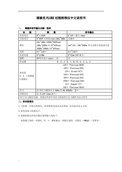
福禄克FLUKE过程校准仪中文说明书一,测量和信号输出功能一览表二、初识校准仪1.当你第一次取出校准仪,你需要将电池充电见图9,给电池充电2小时。
2.将电池放入校准仪中。
3.连接校准仪的电压输出端和输入端如下:连接最左端的一对插孔(V、Ω、RTD输出)和最右端的一对插孔(VMEAS)(见图3)。
图3 跨接线连接图4 输入输出的例子4.开机按⊙,按▲,▼以调整对比度。
以达到最好的显示效果。
校准仪在接通电源时是直流电压的测量功能,可以在一对VMEAS输入插孔中得到读数。
5.按SETUP键,进入输出屏幕显示,校准仪将仍测量直流电压,并且你可以在显示屏顶部看到其测量情况。
6.按V—…键,选择直流电压输出。
按数字键5和ENTER=开始输出5.0000V直流电压。
7.按MEAS SOURCE键,进入双重显示屏幕。
测量、输出同时工作。
校准仪同时输出和测量直流电压。
你将在上半部屏幕看到测量读数,在下半部屏幕看到输出值,如图4所示。
三、操作功能1.输入和输出插孔图5所示,校准器输入和输出插孔,表2解释它的用途。
表2 输入/输出插孔和连接器序号性能说明1 外接电源插孔BE9005电源阻隔器插孔,可在交流电供工作室内使用。
本输入不能给电池充电。
2 !串行接口连接校准仪与个人计算机。
3 压力模块连接器连接校准仪与压力模块4 TC输入/输出测量或模拟输出热电偶插孔。
本插孔接受微型扁平(中心距离7.9mm或0.312英寸)的电偶插头5,6 !MEAS V插孔测量电压、频率、或三线或四线RTDS(热电阻温度计)输入插孔7,8 !SOURCE(输出)mA测量mAΩRTD插孔输出或测量电流、电阻和RTDS插孔,并提供回路电源9,10 !SOURE(输出)V Ω RTD插孔输出电压、电阻、频率、和模拟RTDS输出插孔图5 输入/输出插孔和连接2.按键校准仪按键如图6所示,表3解释它们的功能,有4个未带标记的兰色按键,在显示屏幕下面称之为功能键。
Fluke175 177 179(万用表)说明书

Models 175, 177 & 179True RMS MultimetersMay 2003 Rev. 1, 10/08 (Simplified Chinese)© 2003-2008 Fluke Corporation. All rights reserved. Printed in USA.Specifications are subject to change without notice.All product names are trademarks of their respective companies.终生有限保证Fluke保证每一台Fluke 20、70、80、170和180系列的DMM,其用料和做工都是终生毫无瑕疵的。
此处所谓的“终生”是指Fluke终止制造本产品后七年,但本项保证期应自产品购买日起至少十年内有效。
本项保证不包括保险丝、可弃置的电池以及因疏忽、误用、污染、改变、意外或非正常状况下的使用或处理所造成的损坏(包括使用产品规范以外的测量所引起的故障或机械部件的正常损耗)。
本项保证仅适用于原购买者并且不得转让。
自购买日起十年内,本保证也包括LCD。
十年以后直到仪表的终生,Fluke将以收费的方式更换DMM的LCD(根据当时该组件的成本价格收取费用)。
欲建立原购买者与购买日期的根据,请填妥并寄回产品所附上的注册登记卡,或在上注册产品。
对于从Fluke授权销售处以适当的国际价格所购买而损坏的产品,Fluke可选择免费修理、更换或以原购买价退款的方式处理该产品。
若产品是从一个国家购买却被送到其它地区修理,Fluke保留收取修理/更换零件的进口费用的权利。
如果发现产品损坏,请和最靠近您的Fluke授权服务中心联络以取得同意退回产品的信息,然后请把产品寄到该服务中心。
请说明遭遇到困难的地方,并预付邮资和保险费(目的地离岸价格)。
Fluke不负责产品在运输上的损坏。
福禄克FLUKE-287和FLUKE-87V参数
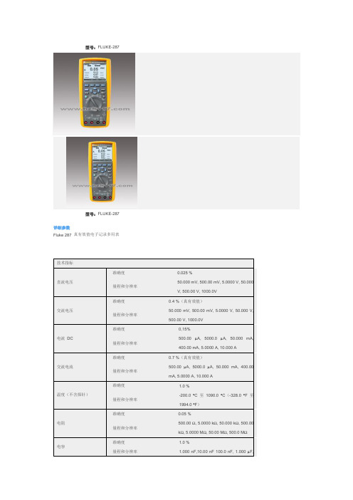
型号:FLUKE-287型号:FLUKE-287详细参数Fluke 287 真有效值电子记录多用表技术指标准确度0.025 %直流电压50.000 mV, 500.00 mV, 5.0000 V, 50.000量程和分辨率V, 500.00 V, 1000.0V准确度0.4 %(真有效值)交流电压50.000 mV, 500.00 mV, 5.0000 V, 50.000 V,量程和分辨率500.00 V, 1000.0V准确度0,15%500.00 µA, 5000.0 µA, 50.000 mA, 电流DC量程和分辨率400.00 mA, 5.0000 A, 10.000 A准确度0.7 %(真有效值)交流电流500.00 µA, 5000.0 µA, 50.000 mA, 400.00量程和分辨率mA, 5.0000 A, 10.000 A准确度 1.0 %温度(不含探针)-200.0 °C 至1090.0 °C(-328.0 °F 至量程和分辨率1994.0 °F)准确度0.05 %电阻500.00 Ω, 5.0000 kΩ, 50.000 kΩ, 500.00量程和分辨率kΩ, 5.0000 MΩ, 50.00 MΩ, 500.0 MΩ准确度 1.0 %电容量程和分辨率 1.000 nF,10.00 nF 100.0 nF, 1.000 µF,10.00 µF, 100.0 µF, 1000 µF, 10.00 mF,100.00 mF Ω频率准确度0.005% + 1量程和分辨率999.99 kHz附加功能/特性多个屏显是真有效值交流带宽100 kHzDBV/dBm 是电导率50.00nS通断蜂鸣器是温度(°C & °F) -200°C 至1090°C电池/保险丝拆装电池/保险丝峰值250 μS计时时钟是时钟是最小-最大-平均是占空比0.01 % 至99.99 %脉宽0.025 ms, 0.25 ms, 2.5 ms, 1250.0 ms 保持是绝缘光学接口是自动/接触保持是读数存储器是记录到PC 是时间间隔/事件记录是记录存储器多达10,000 个读数环境技术指标操作温度-20 °C 至+55 °C 存放温度-40 °C 至+60 °C相对湿度0% 至90%(0 °C 至37 °C)0% 至65%(0 °C 至45 °C)0% 至45%(45 °C 至55 °C)电磁兼容性EMC EN6 1326-1振动随机振动符合MIL-PRF-28800f 标准,2 级仪器撞击 1 米掉落,符合IEC/EN 61010-1 第 2 版安全特性过压保护类别CAT III 1000 V / CAT IV 600 V 安全标准认证CSA, UL, TÜV, CE机械和通用技术指标任意接线端子和接地线之间的最大电压1000V尺寸高x宽x长22.2 cm x 10.2 cm x 6 cm (8.75 in x 4.03 in x 2.38in)重量870.9 g (28 oz)电池寿命最小100 小时,记录模式下200 小时电池类型 6 节AA 电池,NEDA 15A 或IEC LR6型号:FLUKE-87V型号:FLUKE-87V详细参数Fluke 80 系列V 数字多用表技术指标直流电压最大电压:1000V准确度:Fluke 83 V: ±(0.1%+1)Fluke 87 V: ±(0.05%+1) 最大分辨率:Fluke 83 V: 100 µVFluke 87 V: 10 µV交流电压最大电压:1000V准确度:Fluke 83 V: ±(0.5%+2)Fluke 87 V: ±(0.7%+2) 真有效值交流带宽Fluke 83 V: 5kHzFluke 87 V: 20kHz**使用低通滤波器;3db @ 1kHz 最大分辨率:0.1 mV直流电流(20 A ,30 秒,最大) 最大电流:10A电流准确度:Fluke 83 V: ±(0.4%+2)Fluke 87 V: ±(0.2%+2) 最大分辨率:Fluke 83 V: 0.01 mAFluke 87 V: 0.01 µA交流电流(20 A ,30 秒,最大)最大电流:10A电流准确度:Fluke 83 V: ±(1.2%+2)Fluke 87 V: ±(1.0%+2) 真有效值最大分辨率:0.1 µA电阻最大电阻:50 MΩ准确度:Fluke 83 V: ±(0.4%+1)Fluke 87 V: ±(0.2%+1) 最大分辨率:0.1Ω电容最大电容9,999 µF 准确度±(1%+2) 最大分辨率0.01 nF频率最大频率200 kHz准确度±(0.005%+1) 最大分辨率0.01 Hz占空比最大占空比准确度±(0.2% /khz +0.1%) 最大分辨率温度测量Fluke 83 V, 87 V/E: -200.0°C - 1090°C-328.0°F - 1994.0°F不包括探头。
福禄克 Fluke 287真有效值电子记录万用表 内存易失性声明 说明书
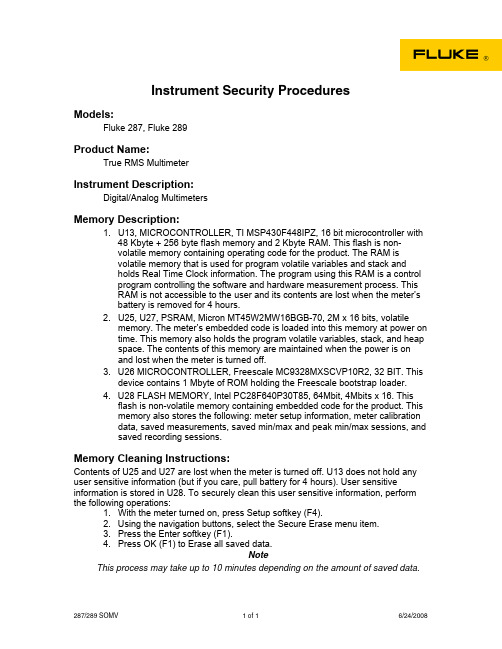
Instrument Security ProceduresModels:Fluke 287, Fluke 289Product Name:True RMS MultimeterInstrument Description:Digital/Analog MultimetersMemory Description:1. U13, MICROCONTROLLER, TI MSP430F448IPZ, 16 bit microcontroller with48 Kbyte + 256 byte flash memory and 2 Kbyte RAM. This flash is non-volatile memory containing operating code for the product. The RAM isvolatile memory that is used for program volatile variables and stack andholds Real Time Clock information. The program using this RAM is a controlprogram controlling the software and hardware measurement process. ThisRAM is not accessible to the user and its contents are lost when the meter’sbattery is removed for 4 hours.2. U25, U27, PSRAM, Micron MT45W2MW16BGB-70, 2M x 16 bits, volatilememory. The meter’s embedded code is loaded into this memory at power ontime. This memory also holds the program volatile variables, stack, and heapspace. The contents of this memory are maintained when the power is onand lost when the meter is turned off.3. U26 MICROCONTROLLER, Freescale MC9328MXSCVP10R2, 32 BIT. Thisdevice contains 1 Mbyte of ROM holding the Freescale bootstrap loader.4. U28 FLASH MEMORY, Intel PC28F640P30T85, 64Mbit, 4Mbits x 16. Thisflash is non-volatile memory containing embedded code for the product. Thismemory also stores the following: meter setup information, meter calibrationdata, saved measurements, saved min/max and peak min/max sessions, andsaved recording sessions.Memory Cleaning Instructions:Contents of U25 and U27 are lost when the meter is turned off. U13 does not hold any user sensitive information (but if you care, pull battery for 4 hours). User sensitive information is stored in U28. To securely clean this user sensitive information, perform the following operations:1. With the meter turned on, press Setup softkey (F4).2. Using the navigation buttons, select the Secure Erase menu item.3. Press the Enter softkey (F1).4. Press OK (F1) to Erase all saved data.NoteThis process may take up to 10 minutes depending on the amount of saved data. 287/289 SOMV 1 of 1 6/24/2008。
福禄克Fluke a283 FC 真有效值 CAT III 1500 V 无线电流钳 校准手册说明书
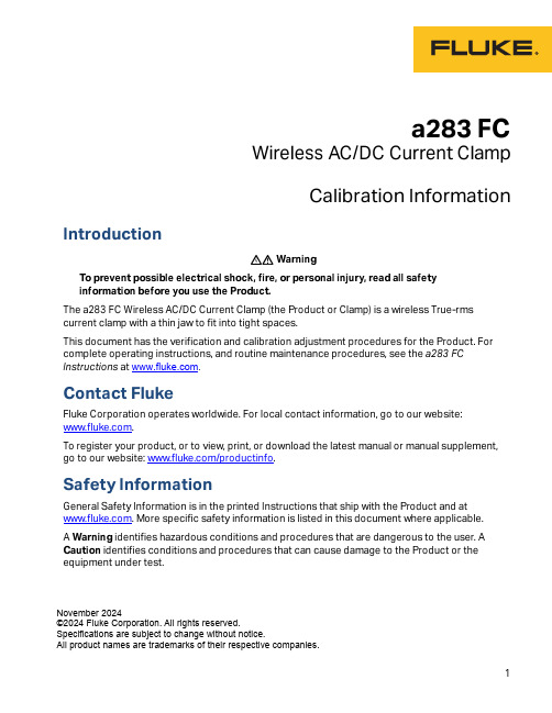
a283 FCWireless AC/DC Current ClampCalibration Information IntroductionXW WarningTo prevent possible electrical shock, fire, or personal injury, read all safetyinformation before you use the Product.The a283 FC Wireless AC/DC Current Clamp (the Product or Clamp) is a wireless True-rms current clamp with a thin jaw to fit into tight spaces.This document has the verification and calibration adjustment procedures for the Product. For complete operating instructions, and routine maintenance procedures, see the a283 FC Instructions at .Contact FlukeFluke Corporation operates worldwide. For local contact information, go to our website:.To register your product, or to view, print, or download the latest manual or manual supplement, go to our website: /productinfo.Safety InformationGeneral Safety Information is in the printed Instructions that ship with the Product and at . More specific safety information is listed in this document where applicable.A Warning identifies hazardous conditions and procedures that are dangerous to the user. A Caution identifies conditions and procedures that can cause damage to the Product or the equipment under test.November 2024©2024 Fluke Corporation. All rights reserved.Specifications are subject to change without notice.All product names are trademarks of their respective companies.a283 FCCalibration InformationXW WarningTo prevent possible electrical shock, fire, or personal injury, keep fingers behind thetactile barrier when you take measurements. See Figure1.Figure 1. Tactile Barrier ArraySpecificationsFor complete specifications, refer to the Users Manual at . Performance TestsXW WarningTo prevent possible electrical shock, fire, or personal injury, do not do theperformance test procedures unless the Product is fully assembled.The performance tests verify the full operation of the Product and measure the accuracy of each function against Product specifications. If the Product fails a part of the test and/or calibrationadjustment, repair is necessary. See Calibration Adjustment.Wireless AC/DC Current ClampPerformance TestsThe performance tests and calibration adjustment require the equipment in Table 1.XW WarningTo prevent possible electrical shock, fire, or personal injury, see the Safety Information document for the 5560A Calibrator available at .Wireless Connection with Fluke 283 FCUse the 283 FC to pair and connect to the Device Under Test (DUT). Check the current output value with the 283 FC. See the 283 FC Users Manual for more detailed information.AC/DC Current TestBefore this test:1.Make sure that you have the necessary equipment. See Table 1.2.Make sure the Product battery is good and replace if necessary.3.Warm up the Calibrator as necessary. Refer to its specifications.4.Let the temperature of the DUT become stable to room temperature.To do the ac/dc current test:1.Place the Product on the 10-turn Coil. See Figure2.2.Connect the Calibrator amp output HI and LO to the 10-Turn Coil. See Figure 2.3.Apply the input current for each step shown in Table 2.pare the indication on the 283 FC with the DUT reading limits in Table 2.5.If the display indication falls outside of the range shown, adjustment or repair of the Productis necessary. See Calibration Adjustment .Table 1. Required EquipmentEquipment Required CharacteristicsRecommended Model Calibrator 4.5-digit resolution AC Current Accuracy:600μA to 30A ±0.25%Fluke 5560A Calibrator (or equivalent)Wired coil 10 turns55XXA/COIL 10Wireless DMM Display current valueFluke 283 FCTTBLE dongleWrite Serial Number for Device Under Test(DUT) and adjust-a283 FCCalibration InformationTable 2. Performance TestsWireless AC/DC Current ClampPerformance Tests Before Calibration AdjustmentBefore you adjust Product calibration, you must turn on the DUT and use the TTBLE dongle to pair and connect to the DUT with the command below.Use the serial communication tool or METCAL to send the command to TTBLE dongle with the serial port set: 115200,8,1,N:AT...AT+BLEMODE=1AT+RESETAT...AT+CLRCONADDAT+SA VEAT+RESETAT...AT+SCAN=ON // wait for the scanned MACAT+CONADD=scanned MACAT+SA VEAT+RESETWhen the PC gets the current value from the DUT, this designates a successful connection.a283 FCCalibration InformationCalibration AdjustmentThe Product features closed-case calibration adjustment and uses known reference sources. The Product measures the applied reference source, calculates correction factors, and stores the correction factors in nonvolatile memory. If the Product fails any of the performance tests, do the calibration adjustment procedure.Connect the Calibrator to the10-turn coil. Clamp the DUT to the coil and then turn on the DUT. See Figure2.Send the command below to check, adjust and change MAC according to serial number of DUT.CAL START // enter calibration mode.LED GREEN // check LEDs colorLED NULL // turn off LEDLED ORANGELED NULLLED REDLED NULLLED BLUELED NULLBALANCE WRITE 124 // step1 Balance, default: 124GET V ALUE//Write and find the value between 32~223 to make the reading difference to be //within ±0.03A at top and bottom of clamp, use GET V ALUE to get reading and //compare.RAW ADCL DATA //step2, ADC zeroRAW ADCH DATA //step3, ADC gainRAW AAC0 DATA//step4, AAC zeroRAW AACL DATA//step5, AAC gainRAW AACM DATA//step6, AAC gainRAW AACH DATA//step7, AAC gainRAW AACMAX DATA//step8, AAC gainIDN WRITE 123456789WS//write in the serial number, example: 123456789WS or 123456789NU// WS: shifu, NU: FPM in NorwichTEMP CALDATE WRITE 20250131// temperature calibration// calibration date, year/month/ dayCAL EXIT // exit the calibration mode.Wireless AC/DC Current ClampMaintenanceRestart the DUT and check the new MAC (serial number) and performance with Fluke 283 FC.For each step in Table 3, output the listed current, and then send the command.MaintenanceClean the ProductW CautionTo prevent possible damage to the Product or to equipment under test, do not useabrasive cleaners. They will damage the case.To clean the Product, use a cloth with a mild cleaning solution.Table 3. Calibration AdjustmentAdjustment PointsSteps Function PointsUnit 5522 Output 1BalanceBalance up:10 turns down:10 turns 60A,60H z6 A, 60 Hz2ADCzeroMiddle:10 turns 0A,0 Hz 0 A3GainMiddle:10 turns 30A,0 Hz 3 A 4AAC zeroMiddle:10 turns 0A,60 Hz 0 A5GainMiddle:10 turns 0.6A,60 Hz 0.06 A,60 Hz 6GainMiddle:10 turns 2A,60 Hz 0.2 A,60 Hz 7GainMiddle:10 turns 30A,60 Hz 3 A,60 Hz 8GainMiddle:10 turns60A,60 Hz6 A,60 Hza283 FCCalibration InformationBattery ReplacementXW WarningTo prevent possible explosion, fire, or personal injury, replace the batteries whenthe low battery indicator (red LED under the power button) shows to preventincorrect measurements.W CautionTo prevent possible damage to the Product or to equipment under test:●Remove batteries to prevent battery leakage and damage to the Product if it is notused for an extended period.●Make sure that the battery polarity is correct to prevent battery leakage.To change the batteries, see Figure3.1.Make sure the Product is OFF.2.Turn the Product over to access the battery compartment door screw.e a flat-head screwdriver to loosen the battery compartment door screw and lift off thebattery compartment door.4.Replace the two AAA batteries. Make sure to observe the correct polarity before you put thebatteries into the battery compartment door.5.Reattach the battery compartment door.6.Tighten the battery compartment door screw.Figure 3. Replace the BatteriesWireless AC/DC Current ClampUser-Replaceable PartsUser-Replaceable PartsUser-replaceable parts are shown in Table4.Table 4. User-Replaceable PartsFluke Part Number Description Qty2687457BATTERY PAD,URETHANE,ADHESIVE-BACK,20.0MM L,20.0MMW,5.0MM THK1 2838018Battery, AAA, IEC LR032 5591547a283 FC CLAMP-2023,RUBBER,SEAL,BATTERY DOOR1 5009651SCREW,CAPTIVE,M3-0.5X8MM,PAN,PHILLIPS,#2,STEEL,BLACK1 4941124SPRING WASHER,M2.5,CARBON STEEL,NICKEL PL16007834 6007847a283 FCCLAMP-8002 STICKER,TTBLE,CLAMP,APAC,-01a283 FC CLAMP-8003STICKER,TTBLE,CLAMP,EMEA&AME&S.AFRICA,-021a283 FC Calibration Information。
- 1、下载文档前请自行甄别文档内容的完整性,平台不提供额外的编辑、内容补充、找答案等附加服务。
- 2、"仅部分预览"的文档,不可在线预览部分如存在完整性等问题,可反馈申请退款(可完整预览的文档不适用该条件!)。
- 3、如文档侵犯您的权益,请联系客服反馈,我们会尽快为您处理(人工客服工作时间:9:00-18:30)。
FLUKE187/189
真有效值
多用表校准手册
适用于Fluke83/87/88V系列数字多用表
Jhand译
目录
标题页码简介 (1)
联系Fluke (1)
预防和安全信息 (2)
电气符号 (2)
技术指标 (5)
精度 (5)
特性概要 (5)
基本技术指标 (6)
详细精度技术指标 (7)
频率计数器灵敏度 (10)
负载电压(A,mA,μA) (10)
输入特性 (10)
所需设备 (11)
基本维护 (12)
数表表壳的开启 (12)
电路板组件的拆卸和安装 (12)
更换LCD (13)
数表表壳的重新安装 (14)
测试保险管(F1和F2) (14)
更换保险 (15)
更换电池 (15)
清洁数表 (16)
性能测试 (17)
测试显示屏 (17)
测试背光 (17)
电流插孔感应能力测试 (17)
按键测试 (18)
IR通信端口验证 (18)
测试温度 (18)
测试电压、电流、电阻、电容和二级管功能 (19)
校准 (23)
按键接口 (23)
一般步骤 (24)
特殊需求 (24)
校准输入 (24)
远程接口 (27)
温度校准 (27)
设置 (27)
步骤 (27)
重新对序列号或型号进行编程 (28)
部件和附件 (29)
校准
数表应当每年进行一次校准,以确保性能满足技术指标的要求。
在校准前,首先在数表后盖上(在附件支架)下找到校准按键,该按键位于校准标签的下面,如图5所示,小心地用校准工具刺破校准标签,按下校准按钮就可以启动校准。
图5. 校准按键的位置
按键接口
启动校准步骤时,将拨动开关置于DC mV位置,然后按住数表的校准按键一秒钟,此时数表进入如图6所示的校准模式,数表将保持在校准状态,直到拨动开关被置于OFF为止。
图6.校准显示
一般步骤
每个所要校准的功能都需要一系列的信号输入,在第二显示位置显示了下一步校准所需要的输入信号,主显示显示的是测量值,测量值与所施加的信号可能会有所不同,这是因为显示的是为校准的测量结果,校准的一般步骤如下:
1.将拨动开关置于你所要校准的功能。
2.按照第二显示的数字设置标准装置的输出。
3.等待一段时间直到主显示上的测量结果稳定。
4.按下UP按键进行下一个校准步骤,数表将记录新的校准因子。
5.重复步骤2至4,直到第二显示处出现End。
这表明该测量功能的校准步骤已经完成,在出现End之前,新的校准因子并不会被保存。
6.如果还有其它功能需要校准,将拨动开关置于响应的功能,然后从步骤1开始校准,否则,将拨动开关置于OFF位置以退出校准。
注意
DC mV校准对所有功能都会产生影响,而AC mV校准将影响所有交流测量功能。
如果校准器的输出与校准点的正常值相差超过15%,那么工厂默认校准常数将自动启用,以替代标准源的输出,此时,数表可能通不过校准测试,因此需要再校准。
特殊需求
DC mV校准会对所有测量功能产生影响,因此,DC mV的校准必须在其它功能校准前进行,同样的,AC mV的校准必须在其它AC功能校准之前进行。
在DC mV校准后,其它
功能的校准的次序可以随意。
温度校准只需要在更换以下元件后进行:U4 A/D芯片,U10 EEPROM或U100 基准节点传感器。
温度校准的过程如下:通过测量一个外部温度然后输入测量结果计算校准因子,然后把校准因子保存在校准存储器中,这个过程是通过串行接口进行的,细节请参阅“温度校准”章节。
当用户更换了U10 EEPROM,必须重新输入数表的序列号和型号,细节请参阅“重新对序列号或型号进行编程”章节。
校准输入
表5列出了每个校准步骤所需要的校准输入。
注意
稳定时间一列中的时间并不包括校准器的稳定时间。
表5.校准输入
步骤数值频率稳定时间(秒)
DC mV
mV DC 16
1 0
mV DC 16
2 50
mV DC 7
3 300
mV DC 7
4 500
mV DC 1
5 3000
温度
1 0 1
AC mV
1 700 mV 700 Hz 7
2 400 mV 700 Hz 7
3 100 mV 700 Hz 7
4 50 mV 700 Hz 7
5 3000 mV 700 Hz 7
1.使用5520A的2线补偿模式。
2.在电阻校准的其它点,欧姆清零后必须使用同一台校准器和测试电缆.
3.由于耦合电容的影响,测量结果可能会受测试电缆或操作人员移动的影响,将手指放在UP按键上,
待测量结果稳定后再按下。
表5.校准输入(序)
步骤数值频率稳定时间(秒)
AC V
1 5 V 700 Hz 7
2 50 V 700 Hz 7
3 500 V 700 Hz 7
4 500 V 700 Hz 7
DC V
1 5V DC 7
2 50 V DC 7
3 500 V DC 7
4 500 V DC 7
Ohms1
12、0 Ohms 16
2 500 Ohms 16
3 5k Ohms 7
Ohms
4 50k Ohms 7
5 500k Ohms 7
6 5M Ohms 73
7 30M Ohms 13
AC uA
1 500 uA 700 Hz 7
2 5000 uA 700 Hz 7
DC uA
1 500 uA DC 16
2 5000 uA DC 7
AC mA
1 50 mA 700 Hz 7
2 400 mA 700 Hz 7
DC mA
1 50 mA DC 16
2 400 mA DC 7
1.使用5520A的2线补偿模式。
2.在电阻校准的其它点,欧姆清零后必须使用同一台校准器和测试电缆.
3.由于耦合电容的影响,测量结果可能会受测试电缆或操作人员移动的影响,将手指放在UP按键上,待测量结果稳定后再按下。
表5.校准输入(序)
步骤数值频率稳定时间(秒)
AC A
1 5 A 700 Hz 7
2 5 A 700 Hz 7
DC A
A DC 16
1 5
A DC 7
2 5
1.使用5520A的2线补偿模式。
2.在电阻校准的其它点,欧姆清零后必须使用同一台校准器和测试电缆.
3.由于耦合电容的影响,测量结果可能会受测试电缆或操作人员移动的影响,将手指放在UP按键上,
待测量结果稳定后再按下。
远程接口
通过远程接口借助MET/CAL软件,用户可以进行半自动校准。
温度校准
所需设备:
● Fluke87/89-IV,187/189维护软件,Fluke P/N676152。
●红外串行电缆套件,Fluke P/N 1590638
●个人电脑
● Fluke80T-150U精度为±0.2℃
● Fluke 8060A 数字多用表
注意
以下的校准步骤只有在数表经过修理并更换了以下元件之一时才需要进行。
这些元件是:U4 A/D芯片,U10 EEPROM或U100 基准节点传感器。
设置
在开始校准前,将拨动开关置于OFF位置,让数表静置在恒温环境中30分钟,这可以使内部的基准节点传感器和输入插孔的稳定到同一温度。
将红外串行电缆连接到电脑的串行口,安装87/89-IV,187/189维护软件。
步骤
在拨动开关置于OFF位置时,将80T-150探头插入数表的COM插孔中(与基准节点的温度相同)。
确保探头与插孔紧密接触,测量并记录COM插孔的温度并以1/100℃为单位记
录此时的测量值,不要把这个温度装换位华氏温度,即使是数表正在使用华氏刻度作为显示输出。
将拨动开关置于温度位置,不管数表是否出于校准模式,在维护软件的菜单中,点击℃Ref. Junction。
在下一个文本框中输入温度值,然后点击OK,此时计算机通过红外串行电缆将基准节点的温度值传送到数表中。
尽管温度校准并未结束,但是此时将关闭数表电源是安全的,这样做的结果会使先前的步骤失效。
要完成温度校准,必须对DC mV功能进行校准。
在DC mV校准完成后:
1.将拨动开关转换到温度位置,按下数表后盖上的校准按钮使数表进入校准模式。
在通常用来显示所需输入值得第二显示上,出现zero字样,此时,不需要任何输入。
2.按下UP按键
此时所计算的温度修正系数被保存到EEPROM中,并结束温度校准。
3.对其它功能进行校准或将拨动开关置于OFF位置退出校准。
重新对序列号或型号进行编程
当更换了U10EEPROM后,用户必须重新输入数表的序列号和型号,如下进行操作:
1.将红外串行电缆连接到电脑,安装87/89-IV,187/189维护软件(Fluke P/N 676152)。
2.将数表的拨动开关置于任何一个功能。
3.在维护软件的菜单中,点击EEPROM,再文本框中输入序列号点击OK,输入数表型号时,在型号菜单对话框中点击Yes或No。