XL4201 中文规格书
完整word版,产品技术规格书模版
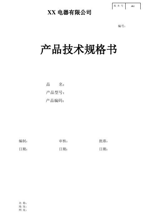
XX 电器有限公司编号:名 称: 地 址:产品技术规格书品 名: 产品型号:产品编码:编制: 审核: 批准: 日期: 日期: 日期:1.基本信息本承认书规定了进水阀的关键参数,性能要求,检验标准,测试标准,抽样判定规则及生产工艺、包装运输等1.1产品概述:本实用新型产品是属于水阀类,是一进一出单阀控制的进水阀,是一种用来控制流体的自动化基础元件,属于执行器;生活中用于控制水的流动或停止,一般会用到这种电磁阀。
其工作原理是,电磁阀里有密闭的腔,当线圈通电时,电磁铁芯吸合,卸压孔打开,在进水咀介质的压力推动,打开主阀口,介质流通。
当线圈断电时,弹簧复位并推动阀芯和伸缩套封住卸压孔,主阀口关闭,介质截止。
这样通过控制电磁阀的电流就控制了机械运动。
1.2产品结构:结构特点说明,各部件良好配合为关键。
2. 关键参数1. 零件表面光洁,无缺陷,装配牢固可靠,无松动现象,其性能应符合GB/T1291-91的要求;2.额定电压为220V-240V 50/60Hz,额定电流为30±5mA(不通水状态);3.绝缘等级为F级;4.适用水压: 0.02-1.0MPa;5.最大耐水压: 1.6MPa以下,历时10Min无渗漏;6. 绝缘电阻: 导电部分和外露金属部分,非金属部分之间均大于100MΩ;7. 匝间绝缘: 对线圈施加1500V,50Hz的脉冲电压,在示波仪上观察到的是完整的正弦波;8. 电气强度:绝缘电阻通过后,导电部分和外露不通电金属和非金属之间施加3125V 50Hz高压1Min的时间,不应击穿;9. 流量要求:(根据客户要求);10. 绕组温升: <75K;11. 线圈电阻为4.1±0.3KΩ;12. 寿命不小于30000次,常温,额定电压下通5S,断5S为一周期,厂家要每周做一次寿命试验:1)0.02MPa时,5000次;2)0.3MPa时,20000次;3) 0.8MPa时,5000次;13. 噪声,声压级小于55dB(A);14.注公差的塑料件按MT5,金属件按IT14级验收;15. 电磁部分的工作按连续工作考核。
XL2001规格书(官方版)

XL2001规格书(官⽅版)5V/1.8A 150KHz 45V Buck DC to DC Converter For USB Interface XL2001Featuresn Wide 8V to 45V input voltage range.n Fixed 5V output voltage.n Maximum 1.8A output current.n Fixed 150KHz switching frequency.n Internal optimize power MOSFET.n High efficiency up to 92%.n Built in output short shutdown function. n Excellent line and load regulation.n Built in thermal shutdown function.n Built in current limit function.n Available in SOIC-8 package. Applicationsn Car Charger.n Battery Charger.n USB Power Supply. General DescriptionThe XL2001 is a 150 KHz fixed frequency PWM buck (step-down) DC/DC converter, capable of driving a 1.8A load with high efficiency, low ripple and excellent line and load regulation. Requiring a minimum number of external components, the regulator is simple to use and include internal frequency compensation and a fixed-frequency oscillator.The XL2001 built in output short protection function. When short protection function happens, the chip will be shutdown.An internal compensation block is built in to minimize external component count.Figure1. Package Type of XL20015V/1.8A 150KHz 45V Buck DC to DC Converter For USB InterfaceXL2001Pin ConfigurationsFigure2. Pin Configuration of XL2001 (Top View)Table 1 Pin DescriptionPin Number Pin Name Description1 FB Feedback Pin (FB). The feedback threshold voltage is 5V.2 NC No Connected.3 VC Internal V oltage Regulator Bypass Capacity. In typical system application, The VC pin connect a 1uf capacity to VIN.4 VIN Supply V oltage Input Pin. XL2001 operates from 8V to 45V DC voltage. Bypass Vin to GND with a suitably large capacitor to eliminate noise on the input.5,6 SW Power Switch Output Pin (SW). SW is the switch node that supplies power to the output.7,8 GND Ground Pin. Care must be taken in layout. This pin should be placed outside of the schottky diode to output capacitor ground path to prevent switching current spikes from inducing voltage noise into XL2001.5V/1.8A 150KHz 45V Buck DC to DC Converter For USB Interface XL2001 Function BlockFigure3. Function Block Diagram of XL2001Typical Application CircuitFigure4. XL2001Typical Application Circuit (VIN=8V~45V, VOUT=5V/1.8A)5V/1.8A 150KHz 45V Buck DC to DC Converter For USB Interface XL2001 Ordering InformationPart Number Marking ID Lead Free Lead Free Packing TypePackage TemperatureRangeXL2001E1 XL2001E1 2500 Units on Tape & ReelXLSEMI Pb-free products, as designated with “E1” suffix in the par number, are RoHS compliant.Absolute Maximum Ratings(Note1)Parameter Symbol Value Unit Input Voltage Vin -0.3 to 50 V Feedback Pin Voltage V FB-0.3 to Vin V Output Switch Pin Voltage V Output-0.3 to Vin V Power Dissipation P D Internally limited mW Thermal Resistance (SOP8L)(Junction to Ambient, No Heatsink, Free Air)R JA100 oC/W Operating Junction Temperature T J-40 to 125 oC Storage Temperature T STG-65 to 150 oC Lead Temperature (Soldering, 10 sec) T LEAD260 oC ESD (HBM) >2000 V Note1: Stresses greater than those listed under Maximum Ratings may cause permanent damage to the device. This is a stress rating only and functional operation of the device at these or any other conditions above those indicated in the operation is not implied. Exposure to absolute maximum rating conditions for extended periods may affect reliability.5V/1.8A 150KHz 45V Buck DC to DC Converter For USB Interface XL2001 XL2001 Electrical CharacteristicsT a = 25℃;unless otherwise specified.Symbol Parameter Test Condition Min. Typ. Max. Unit System parameters test circuit figure4VFB FeedbackV oltageVin = 8V to 45V, V out=5VIload=0.5A to 1.8A4.9 55.1 VEfficiency ?Vin=12V ,V out=5VIout=1.8A- 90 - %Electrical Characteristics (DC Parameters)Vin = 12V, GND=0V, Vin & GND parallel connect a 47uF/50V capacitor; Iout=500mA, T a = 25℃; the others floating unless otherwise specified.Parameters Symbol Test Condition Min. Typ. Max. Unit Input operation voltage Vin 8 45 V Quiescent Supply Current I q V FB =Vin 4.7 10 mA Output Short Supply Current Iosp 5 mA Oscillator Frequency Fosc 128 150 173 KHz Switch Current Limit I L V FB =0 2 AOutput Power PMOS Rdson V FB=0V, Vin=12V,I SW=1.8A60 80 mohm5V/1.8A 150KHz 45V Buck DC to DC Converter For USB InterfaceXL2001Typical System Application (VOUT=5V/1.8A)50010001500200025000.00.51.01.52.02.53.03.54.04.55.05.5Output voltage VS Output currentO u t p u t v o l t a g e (V )Output current(mA)Figure6. XL2001 System Output Constant Current Curve5V/1.8A 150KHz 45V Buck DC to DC Converter For USB Interface XL2001404550556065707580859095100Efficiency VS Load currentE f f i c i e n c y (%)Load current(A)Figure7. XL2001 System Efficiency Curve5V/1.8A 150KHz 45V Buck DC to DC Converter For USB Interface XL2001Output short shutdown function descriptionThe output short shutdown function is built in XL2001. The short protection circuit monitors the output voltage, whenever FB pin voltage is below 1.5V, the short circuit protection circuit is triggered, the converter will be shutdown, input current less than 5mA.When the short fault is removed ,if output load is floating, then converter will restart up, the output voltage will return to normal; if output load isn ’t floating, then converter must be power reset , the output voltage will comeback.Figure8. The converter will be shutdown when output short happen.81012141618202224262830323436384042441.01.11.21.31.41.51.61.71.81.92.0Input current VS Input voltageI n p u t c u r r e n t (m A )Input voltage(V)Figure9. The input current curve when output short happen.VOUTSwithing5V/1.8A 150KHz 45V Buck DC to DC Converter For USB Interface XL2001Package InformationSOP8 Package Mechanical Dimensions5V/1.8A 150KHz 45V Buck DC to DC Converter For USB Interface XL2001Featuresn Wide 8V to 45V input voltage range.n Fixed 5V output voltage.n Maximum 1.8A output current.n Fixed 150KHz switching frequency.n Internal optimize power MOSFET.n High efficiency up to 92%.n Built in output short shutdown function. n Excellent line and load regulation.n Built in thermal shutdown function.n Built in current limit function.n Available in SOIC-8 package. Applicationsn Car Charger.n Battery Charger.n USB Power Supply. General DescriptionThe XL2001 is a 150 KHz fixed frequency PWM buck (step-down) DC/DC converter, capable of driving a 1.8A load with high efficiency, low ripple and excellent line and load regulation. Requiring a minimum number of external components, the regulator is simple to use and include internal frequency compensation and a fixed-frequency oscillator.The XL2001 built in output short protection function. When short protection function happens, the chip will be shutdown.Aninternal compensation block is built in to minimize external component count.。
STAR MICRONICS CO.,LTD. NX-4109 针窄行平推票据用打印机 说明书

NX-410操作手册序 言承蒙惠顾,购得STAR NX-410 打印机。
在使用本机前,请详细阅读本用户手册,以便能正确使用。
并且请妥善保存手册光盘,万一不了解打印机的各项性能或发生故障时,软件光盘会给您很大的帮助。
您所购的STAR NX-410打印机,STAR公司将为您提供三年免费保修服务。
如出现问题请与当地STAR授权维修商联系,或致电北京斯大天星打印维修有限公司。
维修咨询电话北京斯大天星打印机维修有限公司电话:(010) 62501499 62501772传真:(010) 62501116http://目 录目 录 (1)第一章 如何安装打印机 (3)1-1 打印机放置环境的选择 (3)1-2 打印机的开箱检查 (4)1-3 打印机外型结构 (5)1-4 安装打印机 (6)1-5 安装打印机数据线 (10)第二章 安装使用打印纸 (12)2-1 打印纸的使用 (12)1、打印纸的使用范围 (12)2、纸张的打印区域 (13)2-2 使用单页纸或多层纸(平推进纸) (14)第三章打印机控制面板 (15)3-1 控制面板的定义 (16)3-2 联机状态下的面板功能操作 (17)3-3 脱机状态下的面板功能操作 (19)3-4 面板操作开机功能 (22)第四章 调整打印机设置 (23)4-1 安装打印机驱动程序 (23)1、打印机驱动的安装 (23)2、使用打印驱动程序 (27)4-2 打印机EDS设置 (28)1、基本概念 (28)2、控制面板操作更改EDS设置 (29)3、计算机操作更改EDS设置 (31)4-3 EDS设置的功能 (33)1、EDS-1 设置 (33)2、EDS-2 设置 (36)3、EDS-3 设置 (38)4-4使用点调整模式,调校打印机 (41)1、进入点调整模式 (41)2、使用点调整模式 (42)第五章 打印机控制码 (43)5-1 概述 (43)5-2 ESC/P控制码 (44)第六章 维护与保养 (49)6-1 一般保养与使用注意事项 (49)6-2 一般故障与简单处理 (50)第七章 附 录 (52)7-1 打印机规格 (52)7-2 并行接口引脚功能 (54)7-3 打印机面板操作简图 (55)7-4 打印机字符组 (57)第一章 如何安装打印机本章描述如何安装一台新的打印机,安装步骤如下:z选择放置打印机环境z开箱z打印机各部分名称z安装盒式色带z将打印机连接到计算机上如需用打印机可选附件,安装打印机后,请参考附表选件。
MBRS4201T3G;中文规格书,Datasheet资料

ON Semiconductor MBRS4201 eliminates reverse recovery oscillations present in Ultrafast devices in the market, particularly at hot temperatures. *Test Conditions: IF = 1 A, dI/dT = 100 A/ms, VR = 30 V
Mechanical Characteristics
AYWW B421G G
Small Compact Surface Mount Package with J–Bend Leads Rectangular Package for Automated Handling Weight: 217 mg (Approximately) Finish: All External Surfaces Corrosion Resistant and Terminal Leads are Readily Solderable Lead and Mounting Surface Temperature for Soldering Purposes: 260C Maximum for 10 Seconds ESD Ratings: Machine Model = A Human Body Model = 1C Polarity: Notch in Plastic Body Indicates Cathode Lead
*For additional information on our Pb−Free strategy and soldering details, please download the ON Semiconductor Soldering and Mounting Techniques Reference Manual, SOLDERRM/D.
CDCE72010EVM;中文规格书,Datasheet资料

User's GuideSLAU250–May2008This user's guide discusses the general operation and configuration of the Texas Instruments CDCE72010 evaluation board.Contents1Features (2)2General Description (2)3Signal Path and Control Circuitry (3)4Software Selectable Options (3)5Installing the GUI Interface and USB Driver (3)6CDCE72010Control GUI Interface (5)7TI CDCE72010Control GUI Interface (5)7.1Using Software-Enabled PLL Selection (5)8Configuring the Board (10)8.1Default Configuration for Programming and Testing With USB Cable Attached (10)8.2Configuration for Programming With USB Cable Attached (10)8.3Configuration for Testing From a Saved Configuration With USB Cable Removed AfterProgramming (10)8.4Configuration for Onboard External Loop Filter (11)8.5Configuration for PLL Lock Detect (12)9CDCE72010EVM Board Schematic Diagram (13)List of Figures1CDCE72010EVM Board (2)2CDCE72010EVM External Loop Filter Topology (12)Windows is a trademark of Microsoft Corporartion.1Features2General DescriptionFeatures •Easy-to-use evaluation board to generate low-phase noise clocks up to 1.5GHz •Easy device programming via host-powered USB port •Fast configuration through provided graphical user interface (GUI)software interface •Total board power provided either through USB port or separate 3.3V and ground connections.•Single-ended or differential input reference clock •Crystal filter on output readily available for clocking high-speed analog-to-digital converters,if needed.Figure 1.CDCE72010EVM BoardThe CDCE72010is a high-performance,low-phase noise clock synchronizer and jitter cleaner.It has one main universal VCO/VCXO input buffer and an auxiliary universal input buffer.Either Input can drive the outputs and/or the feedback path to the PFD.The maximum VCXO/VCO input frequency is 1.5GHz.Itprovides support for two redundant input references and using its on-chip PLL architecture can provide up to ten differential or 20single-ended low jitter outputs.The CDCE72010supports two reference inputs,which can be differential or single-ended.It also provides two VCXO inputs,which can drive up to ten outputs.The CDCE72010then can be programmed through the SPI interface using the evaluation module (EVM)programming GUI.The evaluation module (EVM)is designed to demonstrate the electrical performance of the device.This fully assembled and factory-tested evaluation board allows complete validation of all device functions.For optimum performance,the board is equipped with 50-ΩSMA connectors and well-controlled 50-Ωimpedance microstrip transmission lines.1.5-GHz Low-Phase Noise Clock Evaluation Board 2SLAU250–May 2008 Signal Path and Control Circuitry 3Signal Path and Control CircuitryThe CDCE72010provides support for selectable tri-inputs,and two of the inputs(PRI REF and SEC REF) can accept a8-kHz to500-MHz frequency input from a differential signal source or a8-kHz to200-MHz frequency input from a single-ended signal source.The CDCE72010provides support for up to ten differential(LVDS or LVPECL)or20single-ended(LVCMOS)or any combination of outputs up to1.5GHz.On the CDCE72010EVM,output1and output8 have a footprint option for installing crystal filters that can drive the phase noise floor down by10dB or15 db.This filtered signal is intended to be used for clocking high-performance,high-speed analog-to-digital converters(ADC).The CDCE72010requires an external loop filter.The loop filter selection determines the PLL loop stability and also affects the phase noise of the output.The EVM provides four sets of filters optimized for a30.72-MHz reference and491.52-MHz VCXO.For any output of the CDCE72010,the frequency isdetermined by the selection of the VCO/VCXO and the setting of the output divider.The output jitterperformance is determined by the PLL settings(including the PFD frequency,charge pump current,and the loop filter).See the CDCE72010data sheet for more details and configuration settings.Each of the ten outputs of the CDCE72010can be selected through the software interface as LVPECL, LVDS,or LVCMOS.The CDCE72010EVM provides software selectable150-Ωcurrent-setting resistors.The LVCMOS outputs work for frequencies up to250MHz;the LVDS outputs run up to800MHz;and LVPECL outputs function up to1.175MHz(these are all minimum frequencies).4Software Selectable OptionsThe provided GUI software allows users to easily send commands to the CDCE72010through thehost-powered USB interface.The EVM includes a slave USB controller that transmits the commands to the SPI programming interface included on the CDCE72010.The DC power for the USB controller can either be derived from the5-V power pin in the USB cable or by using an external5-V DC adapter into the slot available on the EVM.If the device is accessible for programming by the SPI programming interface through the USB controller,the onboard LED D25is illuminated on power up.In addition to writing commands to the CDCE72010RAM while the board is powered,commands also can be stored in CDCE72010EEPROM.This allows users to start the EVM in the desired state withoutneeding programming at power up.Note that the CDCE72010has a permanent EEPROM lock mode.After this mode is selected,theEEPROM within the CDCE72010cannot be changed.This is useful when setting final configurations.The CDCE72010EVM software also provides support for the device GUI configurations to be saved into a configuration file,which can be opened at a later time with this GUI.5Installing the GUI Interface and USB DriverTo start installation,run the CDCE72010Control GUI v1.X.X.msi file.Make note of the installation folder because you may need to refer to it when the USB cable is connected and asks for the location of a driver file.After the setup wizard has completed,start the GUI interface from the start menu(Start→CDCE72010 Control GUI).Installing the GUI Interface and USB Driver Connect the USB cable to the EVM.If The Windows™operating system asks for an appropriate driver,do not use the automatic search option.Select a manual installation,and when prompted for the driverlocation,browse to the CDCE72010GUI file folder that was used during instillation.If the Windowsoperating system does not ask for a driver,no action is required.After the USB driver installation,the GUI software must connect properly and be ready for use.A green light in the USB Status and SPI Bus Status boxes indicates good USB connection,and a red lightindicates faulty USB connection or faulty SPI bus.1.5-GHz Low-Phase Noise Clock Evaluation Board 4SLAU250–May 20086CDCE72010Control GUIInterface7TI CDCE72010Control GUI Interface 7.1Using Software-Enabled PLL Selection CDCE72010Control GUI Interface The illustration in the software shows the block diagram of the CDCE72010.In this illustration,the usercan change the Input Frequency,Input Divider,Input type,Input selection,PFD Charge Pump,OutputDivider,and Output type.The rest are selected by the software with user-selectable options as described in the steps below.If the power to the CDCE72010is derived from the USB,the Enable EVM Powerbutton needs to be checked.If the power to the CDCE72010is derived from an external source,theEnable EVM Power button needs to be unchecked.TI CDCE72010Control GUI Interface Step1:External Control Pins SelectionBefore programming the PLL,select the External Control Pins button in the EVM Status section of theGUI.The selections on this popup window,as shown in the following illustration,must be selectedaccording to the desired working configuration of the CDCE72010.6 1.5-GHz Low-Phase Noise Clock Evaluation Board SLAU250–May2008 TI CDCE72010Control GUI Interface Step2:Primary/Secondary Reference Input SelectionThe primary or the secondary reference input buffer section on the GUI can be clicked for a popup window that opens up,as shown in the following illustration.This illustration shows selections on the external input signal type(differential or single ended),the external signal connection to the CDCE72010primary/secondary inputs(AC or DC termination),input buffer internal termination(enabled or disabled), input buffer VBB voltage polarity(normal or inverted),input buffer hysteresis,and fail-safe mode(enabled or disabled).Step3:Reference Input Selection through Smart MUXThe Smart MUX section of the GUI can be clicked for a popup window that opens up as displayed in the following illustration,showing selections of Primary,Secondary,Auto(with Primary preference),andNone.TI CDCE72010Control GUI Interface Step4:PFD and Charge Pump SelectionThe PFD and Charge Pump section of the GUI can be clicked for a popup window that opens up.Thefollowing illustration shows selections on the charge pump current and charge pump pulse width.Step5:Output DividerThe CDCE72010has10outputs and8Output Dividers.Outputs0and1share the same divider,andoutputs8and9share the same divider.The Output Divider and the Output Phase Adjust are accessed by clicking on the divider needed.8 1.5-GHz Low-Phase Noise Clock Evaluation Board SLAU250–May2008 TI CDCE72010Control GUI Interface Step6:Output Type SelectionThe Output Buffer section of the GUI for each of the five outputs can be clicked for a popup window that opens up,as displayed in the following illustration.For each output clock source,the user can selectLVPECL,LVPECL High Swing(in which cases the output150-Ωtermination is automatically enabled), LVDS,LVDS High Swing,or LVCMOS.In CMOS mode,the P and N outputs become separate CMOS outputs running at the same frequency.Either CMOS output can be active,inverting,tri-state or low.Each output can be independently disabled.Step7:Write to CDCE72010EEPROMTo write any particular setting to the EEPROM(locked or unlocked),the menu item at the top of the GUI entitled Tool must be clicked which reveals the items Write EEPROM Unlocked and Write EEPROMLocked as part of a drop-down menu.Choosing the appropriate one after setting the desired PLLconfigurations results in writing to the EEPROM in the selected mode.8Configuring the Board8.1Default Configuration for Programming and Testing With USB Cable Attached8.2Configuration for Programming With USB CableAttached8.3Configuration for Testing From a Saved Configuration With USB Cable Removed Configuring the Board The CDCE72010EVM can be powered from the USB power supply or from an external source.TheCDCE72010EVM only needs a USB cable attached for programming purposes.However,for testmeasurements,it is recommended to also use an external 3.3-V power supply.Test measurements also can be taken with only the USB-supplied power.However,due to USB port power limitations,results may degrade.It is also possible to program the CDCE72010and then disconnect the USB cable (may require minor board configuration changes).The CDCE72010EVM is configured by default to operate with the USB cable attached and a 3.3-V power supply added to EXT VDD and GND.In this configuration,the USB microcontroller is powered by the USB port’s 5-V supply whereas the CDCE72010is powered by the 3.3-V external supply.This setup is optimal for programming the CDCE72010while also taking measurements.This configuration removes the power variation found in USB power supplies by isolating the CDCE72010from the USB supply.The CDCE72010EVM can use power supplied through the USB cable as its sole power source.However,due to power supply variances in the USB supply,this configuration is not recommended formeasurements.This setup is for saving configuration settings to the CDCE72010and later powering the device from its internal memory (useful if a USB port is unavailable in a laboratory or test chamber).In this configuration,JP_3_3must be moved from its default position to the new position shown in the following illustration.Also,the Enable EVM Power box must be checked on the EVM GUI interface software.After ProgrammingWhen operating the CDCE72010without the USB programming cable (useful in laboratory settings inwhich a PC is unavailable at the laboratory station),the CDCE72010needs to be configured and saved in the EEPROM in one of the preceding configurations and then reconfigured for external power supplyusage.Prior to making these board modifications,the CDCE72010settings must be saved with one of the USB cable attached configurations.The Write EEPROM Unlocked or Write EEPROM Locked software button must be used to save the CDCE72010to its internal EEPROM.After the settings are saved to EEPROM,the USB cable can be removed.Once the cable has been disconnected,JP_3_3must be in the UsingExternal 3.3V Supply position (as seen in the preceding diagram).The EVM now is ready for use without the USB cable connected.The CDCE72010always starts from its saved configuration state in this mode.10 1.5-GHz Low-Phase Noise Clock Evaluation Board SLAU250–May 2008分销商库存信息: TICDCE72010EVM。
ZNBG2000X10中文资料(Zetex Semiconductors)中文数据手册「EasyDatasheet - 矽搜」

V I V E E fO
电源电压 电源电流 衬底电压 (内部产生) 输出噪声 漏极电压 栅极电压 振荡器频率
Min 5 I I I I
和I 和I
Typ 5 24 -2.8
=10mA -3.5 =10nF =10nF 150
=0 = -200µA
C =4.7nF, C C =4.7nF, C
330
排水特性
CAL2 )
输出电流 工作温度 储存温度
100mA -40至80℃ -40 to 85°C amb 25 C) 500mW
功耗( T
MSOP10
电气特性测试条件(除非另有
符号参数 条件
极限
UNITS Max 12 10 30 -2 -2 0.02 0.005 800 V mA mA V V Vpkpk Vpkpk kHz
V
输出高
I I
Notes: 1. The negative bias voltages specified are generated on-chip using an internal oscillator. Two external capacitors, C and C , of 47nF are required for this purpose. 2. The characteristics are measured using an external reference resistors R of value 16kΩ wired from pin R to ground. 3. Noise voltage is not measured in production. 4. Noise voltage measurement is made with FETs and gate and drain capacitors in place on all outputs. C , 4.7nF, are connected between gate outputs and 第 1期
北洋打印机BTP-L520_ARM9_ 用户手册V1.0

BTP-L520 用户手册
安全须知
在使用打印机之前,请仔细阅读下面的注意事项。 ¾ 安全警告
警告:打印头为发热部件,打印过程中和打印刚结束 时,不要触摸打印头以及周边部件;
警告:不要触摸打印头表面和连接接插件,以免因静 电损坏打印头。
¾ 注意事项 1) 打印机应安装在一个平整、稳固的地方; 2) 在打印机的周围留出足够的空间,以便操作和维护; 3) 打印机应远离水源并避免阳光、强光和热源的直射; 4) 避免在高温、高湿以及污染严重的地方使用和保存打印机; 5) 避免将打印机放在有振动和冲击的地方; 6) 避免打印机的表面结露,如果已经形成,在露水消除之前不 要打开打印机的电源; 7) 将打印机的电源连接到一个适当的接地插座上,避免与大型 电机或其它能够导致电源电压波动的设备使用同一插座; 8) 如果较长时间不使用打印机,请断开打印机的电源; 9) 避免水或导电的物质(例如:金属)进入打印机内部,一旦 发生,请立即关闭电源; 10) 避 免 在 无 纸 状 态 下 打 印 , 否 则 将 严 重 损 害 打 印 胶 辊 和 打 印 头; 11) 为了保证打印质量和产品的寿命,建议采用推荐的或同等质 量的纸张; 12) 插接或断开各个接口时,必须关掉电源,否则可能会引起 打 印机控制电路的损坏;
2 打印机操作 .............................................................................................. 3 2.1 外观和组件 ....................................................................................... 3 2.2 主要组件介绍 ................................................................................... 4 2.3 指示灯、蜂鸣器、按键和液晶功能说明........................................ 5 2.3.1 指示灯功能说明 ........................................................................ 5 2.3.2 按键功能说明 ............................................................................ 5 2.3.3 指示灯和蜂鸣器 ........................................................................ 6 2.3.4 液晶显示功能 ............................................................................ 6 2.4 安装纸卷 ........................................................................................... 8 2.5 启动打印机 ..................................................................................... 11 2.5.1 开机与自检 .............................................................................. 11 2.5.2 打印自检样张 .......................................................................... 11 2.5.3 设置纸张类型 .......................................................................... 11 2.5.4 校验标记 .................................................................................. 12 2.6 软件安装 ......................................................................................... 13 2.6.1 驱动程序安装 .......................................................................... 13 2.6.2 标签软件安装 .......................................................................... 15
2.4寸高分辨率电子纸产品规格书
Good DisplaySpecifications Type: 2.04inch E-Paper Display Module Model No. GDE024A1Description: ● 2.04” 400 x 300 dots Display ●Ultra wide viewing angle●Ultra low power consumptionPrepared: XiaoliLanChecked: MoonWuApproved: BorisJenIssue Date: 2012.6.27Dalian Good Display Co., Ltd.Good DisplayNo.17 Gonghua Street, Shahekou District, Dalian 116021 China Tel: +86-411-84619565 Fax: +86-411-84619585E-mail: info@Website: 2.4” B&W E‐Paper Display ModuleCONTENTSGDE024A1 Technical Specification (1)2.4” E‐Paper Display Module (1)CONTENTS (2)1. GENERAL DESCRIPTION (3)2. FEATURES (3)3. APPLICATION (3)4. ELECTRICAL CHARACTERISTICS (4)5 MECHANICAL DATA (7)6 OPTICAL DATA (10)7. HANDLING, SAFETY AND ENVIROMENTAL REQUIREMENTS (10)8, Reliability test (11)9, Block Diagra (13)2.4” B&W E‐Paper Display Module1. GENERAL DESCRIPTIONHigh‐Resolution AM TFT Black/White display panels, which can be used in portable electronic devices, such as E‐book Reader.The module is a TFT‐array driving electrophoretic display, with integrated circuits including source and gate drivers. The resolution of the panel is 400×300,and the active area is 2.4 inch diagonal.2. FEATURES◆400×300 display◆4:3 aspect ratios◆Ultra wide viewing angle◆Ultra low power consumption◆Pure reflective mode◆Bi –stable display◆Commercial temperature range◆High contrast ratio of 9:1 (Typical)◆High white reflectance of 35% (Typical)◆Fast response with 300ms state‐to‐state switching3. APPLICATIONDocument reader,Cell phone display,E‐book display screenESL display panel2.4” B&W E‐Paper Display Module4. ELECTRICAL CHARACTERISTICS4‐1) Panel interface descriptionThis panel is driven by ASIC GD6201E timing controller.4‐2) Panel DC characteristicsParameter Symbol Conditions Min Typ Max UnitSignal ground VSS ‐ 0 ‐ VLogic Voltage supply VDD 3.0 3.3 3.6 VIVDD VDD=3.3V 35 mAGate Positive supply VGH 19 20 23 VIVGH 100 uAGate Negative supply VGL ‐23 ‐20 ‐19 VIVGL 100 uASource Positive supply VPOS 14.61515.4 VINEG VPOS=15V 10 20 mASource Negative supply VNEG ‐15.4 ‐15 ‐14.6 VIPOS VNEG=‐15V 10 20 mA Asymmetry source VASYM VPOS+VNEG ‐80 0 80 mV Common voltage VCOM ‐2.5 Adjusted ‐1.0 VICOM ‐0.2‐ mAStandby power panel PSTBY ‐0.25 mWTypical power panel PTYP ‐ 300 700 mW Operating temperature 0 50 ℃Storage temperature ‐20‐70 ℃ Maximum image update900 mstime at 25℃The maximum power and maximum current are specified for the worst case power consumption.- The typical power is measured when “typical images” are displayed- The standby power is the consumed power when the panel controller is in standby mode.- The listed electrical/optical characteristics are only guaranteed under the controller & waveform provided by *RRG 'LVSOD\2.4” B&W E‐Paper Display Module4‐3) Panel AC characteristicsVDD=3.0V to 3.6V, unless otherwise specifiedParameter Symbol Min. Typ. Max. Unit App Pin Clock frequency fcpv 200kHz CPV Minimum “L” clock pulse width twL 0.5usClock rise time trcpv 100nsClock fall time tfcpv 100nsData setup time tSU 100ns CPV, STVData hold time tH 100nsPulse rise time trstv 100ns STV Pulse fall time tfstv 100nsClock CLK cycle time tclk 50- - ns Below tableD0 .. D7, SPH setup time tsu 8ns D0 .. D7, SPH hold time th 1ns LE on delay time tLEdly 40ns LE high-level pulse width tLEw 40ns LE off delay time tLEoff 40ns2.4” B&W E‐Paper Display ModuleCLOCK & DATA TIMING2.4” B&W E‐Paper Display Module5 MECHANICAL DATA5.1 DimensionPARAMETER VALUE UNIT RemarkDisplay format 400×300 dotsActive area dimensions WidthHeight5037.5mmmmScreen size 2.4(4:3 diagonal) InchPixel pitchHorizontal Vertical0.1250.125mmmmPixel configuration RectangleOverall dimensions Width Height Depth61.252.051.2mmmmmmMass of the module 5.5 g5.2 Electrical ConnectorsSERVICE CONNECTOR TYPE NUMBER NUMBEROF PINS MATING CONNECTORInterface JST T.B.D 30 Flex Foil,pitch=0.3mm2.4” B&W E‐Paper Display Module5.3 Mechanical Drawing of EPD Module2.4” B&W E‐Paper Display Module5.4 Input/Output Pin Assignment1VNEG Negative power supply source driver2VPOS Positive power supply source driver3VSS Ground4VDD Digital power supply drivers5CL Clock source driver6LE Latch enable source driver7OE Output enable source driver8SHR Shift direction source driver9STL Start pulse source driver10D0 Data signal source driver11D1 Data signal source driver12D2 Data signal source driver13D3 Data signal source driver14D4 Data signal source driver15D5 Data signal source driver16D6 Data signal source driver17D7 Data signal source driver18VCOM Common connection19VGG Positive power supply gate driver20NC NO Connection21VEE Negative power supply gate driver22NC NO Connection23GMODE2 Output mode selection gate driver24GMODE1 Output mode selection gate driver25XRL Shift direction gate driver26XCE1 STV1 output enable control27XCE2 STV2 output enable control28XSPV Start pulse gate driver29CLK Shift clock input30VBORDER Border connection2.4” B&W E‐Paper Display Module6 OPTICAL DATA6.1 Optical characteristicsT amb=25℃; supply voltage module is 3.3V. Measurements are made with Eye‐One Pro Spectrophotometer.Optical PerformanceColor Black and WhiteWhite Reflectivity 35% (typical)Contrast Ratio (CR) 7:1 (typical)Grayscale Capability 3‐bit (8 gray levels)Image Update Time: 900ms (grayscale mode)300 ms (1‐bit mode)Viewing Angle Nearly 180 degree7. HANDLING, SAFETY AND ENVIROMENTAL REQUIREMENTSWARNINGThe display glass may break when it is dropped or bumped on a hard surface. Handle with care. Should the display break, do not touch the electrophoretic material. In case of contact with electrophoretic material, wash with water and soap.CAUTIONThe display module should not be exposed to harmful gases, such as acid and alkali gases, which corrode electronic components. Disassembling the display moduleDisassembling the display module can cause permanent damage and invalidates the warranty agreementsObserve general precautions that are common to handling delicate electronic components. The glass can break and front surfaces can easily be damaged. Moreover the display is sensitive to static electricity and other rough environmental conditions.2.4” B&W E‐Paper Display Module8, Reliability testTEST CONDITION METHOD REMARK1High-TemperatureOperationT = +50°C, RH = 30%for 240 hrsIEC 60068-2-2BpAt the end of the test, electric,mechanical, and opticalspecifications shall be satisfied.2Low-TemperatureOperationT = 0°C for 240 hrs IEC 60068-2-2AbAt the end of the test, electric,mechanical, and opticalspecifications shall be satisfied.3High-TemperatureFunctionalT = +60°C, RH=26%for 240 hrsIEC 60068-2-2BpAt the end of the test, electric,mechanical, and opticalspecifications shall be satisfied.4Low-TemperatureFunctionalT = -10°C for 240 hrs IEC 60068-2-2AbAt the end of the test, electric,mechanical, and opticalspecifications shall be satisfied.5High-TemperatureStorageT = +70°C, RH=23%for 240hrsIEC 60068-2-2BpAt the end of the test, electric,mechanical, and opticalspecifications shall be satisfied.6Low-TemperatureStorageT = -25°C for 240 hrs IEC 60068-2-1AbAt the end of the test, electric,mechanical, and opticalspecifications shall be satisfied.7High-Temperature,High-HumidityOperationT = +40°C, RH = 90%for168 hrsIEC 60068-2-3CAAt the end of the test, electric,mechanical, and opticalspecifications shall be satisfied.8High Temperature,High- HumidityStorageT = +60℃, RH=80%for240hrsIEC 60068-2-3CAAt the end of the test, electric,mechanical, and opticalspecifications shall be satisfied.9Temperature Cycle 1 cycle:[-25℃ 30min]→[+70℃ 30 min] : 100 cyclesIEC 60068-2-14At the end of the test, electric,mechanical, and opticalspecifications shall be satisfied.10UV exposureResistance765 W/m2 for168hrs,40℃IEC60068-2-5SaAt the end of the test, electric,mechanical, and opticalspecifications shall be satisfied.11Package Vibration 1.04G, Frequency:10~500HzDirection: X,Y,ZDuration: 1 hours ineachdirectionFull packedfor shipmentAt the end of the test, electric,mechanical, and opticalspecifications shall be satisfied.12Package DropImpactDrop from height of122 cmon concrete surface.Drop sequence: 1corner, 3edges, 6 facesOne drop for eachfull packedforshipmentAt the end of the test, electric,mechanical, and opticalspecifications shall be satisfied.13Electrostatic Effect(non-operating)Machine model+/- 250V, 0Ω, 200pFIEC 62179,IEC 62180At the end of the test, electric,mechanical, and opticalspecifications shall be satisfied.14Altitude test 700hPa ( = 3000m ) At the end of the test, electric,2.4” B&W E‐Paper Display ModuleOperation 48Hr mechanical, and opticalspecifications shall be satisfied.15Altitude testStorage260hPa ( = 10000m )48HrAt the end of the test, electric,mechanical, and opticalspecifications shall be satisfied.16Stylus Tapping POLYACETAL Pen:TopR0.4mmLoad: 300gfSpeed: 5times/secTotal 13,500times,At the end of the test, electric,mechanical, and opticalspecifications shall be satisfied.2.4” B&W E‐Paper Display Module9, Block Diagra。
0190430020;中文规格书,Datasheet资料
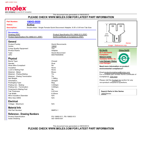
Need more information on product environmental compliance? Email productcompliance@ For a multiple part number RoHS Certificate of Compliance, click here Please visit the Contact Us section for any non-product compliance questions.
/
This document was generated on 09/03/2012
PLEASE CHECK FOR LATEST PART INFORMATION
Part Number: Status: Description:
1sical
Barrel Type Gender Glow-Wire Compliant Insulation Lock to Mating Part Material - Metal Material - Plating Mating Material - Plating Termination Net Weight Orientation Packaging Type Plating min - Mating Plating min - Termination Polarized to Mating Part Tab Thickness Tab Width Wire Insulation Diameter Wire Size AWG Closed Dual No None None Brass Tin Tin 1.596/g Straight Bag 4.064µm 4.064µm No 0.81mm 6.35mm N/A N/A
XL4201原厂原理图BOM和PCB图汇总(中文版)

VOUT (VIN −VOUT )
IRMS≈IMAX*
VIN
其中,最大平均输出电流 IMAX 等于峰值电流与 1/2 峰值纹波电流之差,即 IMAX=ILIM-△IL/2。在未使用陶瓷 电容器时,还建议在输入电容上增加一个 0.1uF 至 1uF 的陶瓷电容器以进行高频去耦。
输出电容选择 在输出端应选择低 ESR 电容以减小输出纹波电压,一般来说,一旦电容 ESR 得到满足,电容就足以满足需求。任 何电容器的 ESR 连同其自身容量将为系统产生一个零点,ESR 值越大,零点位于的频率段越低,而陶瓷电容的零点处 于一个较高的频率上,通常可以忽略,是一种上佳的选择,但与电解电容相比,大容量、高耐压陶瓷电容会体积较大, 成本较高,因此使用 0.1uF 至 1uF 的陶瓷电容与低 ESR 电解电容结合使用是不错的选择。 输出电压纹波由下式决定:
EFF(%) 88.9 95.7 97.0
EFF(%) 83.7 88.5 91.6 91.8 94.2 95.2
Efficiency(%) Output current(mA)
Efficiency VS LED String
100
95
90
85
80
75
70
VIN=8V,IOUT=660mA
VIN=12V,IOUT=660mA
XL4201 为标准 SOP8-EP 封装,集成度高,外围器件少,应用灵活。
DEMO 原理图
VIN 8
2 SW
L1 100uH/3A
ILED=0.11V/RCS LED OVP=1.3*VOUT=1.3*{1.25*(1+R2/R1)}
VIN 8V~40V
CIN
C1
Star针式打印机AR-5400+技术手册

Star针式打印机AR-5400+简体中文技术手册[第二版]引言本手册对于AR-5400+打印机作出了介绍,它是用作周期性检查和维謢的参考手册。
这是一本技术手册而不是普通用户的使用说明书。
●本手册分成如下章节:第一章一般规格第二章操作原理第三章调校第四章部份替换第五章维謢和润滑第六章故障检修第七章器件清单●第一版:2001年12月●第二版:2002年7月第一章一般规格1. 一般规格2. 外观及结构3. 控制面板3-1 开关组合功能3-2 EDS模式设定4. 并行接口4-1 一般规格4-2 接口信号5. 串行接口(可选件)5-1 一般规格5-2 接口信号5-3 DIP开关设置6. EE-PROM模式6-1 概述6-2 特殊控制码的说明6-3 EE-PROM图表6-4 重写EE-PROM1. 一般规格*** 表示半角。
耗电10W (等候状态)42W (草稿英数打印)寿命打印头2亿点/ 针色带LZ24HD:400万字符以上(草稿) 理想打印区域页首:1/6” (4.23mm)页尾:1/6” (4.23mm)彷真状态OKI5330SC (标准)ESC/P (可选)IBM PPDS (可选)操作环境温度:5℃~ 40℃湿度:10% ~ 80% (非结霜状态)MTBF:5000 P.O.H噪音:小于55 dB图1-1 整体尺寸2. 外观及结构图1-2 打印机前视图图1-3 打印机后视图图1-4 揭开面盖前视图图1-5 内部结构图3. 控制面版3-1. 开关组合功能图1-6 面板按钮组合功能3-2. EDS模式设置按住[頁首] 键开机则进入問答主式的EDS模式。
AR5400有三種彷真模式,它們的EDS功能如下:4. 并行接口4-1. 一般规格项目规格接口Centronics兼容同步方式通过外部提供的STROBE脉冲I/F协议通过ACK及BUSY信号逻辑电平与TTL电平相兼容图1-7 并行接口步进图4-2. 接口信号5. 串行接口(可选件)当使用串行接口时,串行-并行转换器应连接上打印机。
WT-01N极致开放小巧易用规格书说明书

WT-01N极致 / 开放 / 小巧 / 易用规格书版本1.02019年05月03日免责申明和版权公告本文中的信息,包括供参考的URL 地址,如有变更,恕不另行通知。
文档“按现状”提供,不负任何担保责任,包括对适销性、适用于特定用途或非侵权性的任何担保,和任何提案、规格或样品在他处提到的任何担保。
本文档不负任何责任,包括使用本文档内信息产生的侵犯任何专利权行为的责任。
本文档在此未以禁止反言或其他方式授予任何知识产权使用许可,不管是明示许可还是暗示许可。
Wi-Fi 联盟成员标志归Wi-Fi 联盟所有。
文中提到的所有商标名称、商标和注册商标均属其各自所有者的财产,特此声明。
注意由于产品版本升级或其他原因,本手册内容有可能变更。
深圳市启明云端科技有限公司保留在没有任何通知或者提示的情况下对本手册的内容进行修改的权利。
本手册仅作为使用指导,深圳市启明云端科技有限公司尽全力在本手册中提供准确的信息,但是深圳市启明云端科技有限公司并不确保手册内容完全没有错误,本手册中的所有陈述、信息和建议也不构成任何明示或暗示的担保。
修改记录目录WT-01N (1)1. 概述 (5)2. 主要特性 (5)3. 硬件规格 (6)3.1 系统框图 (6)3.2引脚描述 (6)3.3电气特性 (8)3.3.1最大额定值 (8)3.3.2建议工作环境 (8)3.3.3数字端口特征 (8)3.4功耗 (8)3.4.1运行功耗 (8)3.4.2待机功耗 (9)3.5RF特性 (9)3.5.1无线局域网射频配置及通用规格 (9)3.5.2射频发射特性 (9)3.5.3射频接收特性 (10)4. 应用说明 (10)4.1模块尺寸 (10)4.2 回流焊曲线图 (11)6. 产品试用 (12)1. 概述WT-01N WiFi模块是由启明云端科技开发的、低功耗高性价比的嵌入式无线网络控制模块。
可满足智能电网、楼宇自动化、安防、智能家居、远程医疗等物联网应用的需求。
GT20L16S1Y规格书V4.0I_B
1.1 芯片特点
● 数据总线:SPI 串行总线接口 ● 点阵排列方式:字节竖置横排 ● 时钟频率:30MHz(max.) @3.3V ● 工作电压:2.2V~3.6V ● 电流:
工作电流:8mA 待机电流:8uA ● 封装:SOT23-6 ● 尺寸 SOT23-6:2.9mmX1.6 mm x1.10mm ● 工作温度:-20℃~70℃
集通数码科技
VER 4.0I_B
2012-1
- 1-
GT20L16S1Y 标准点阵汉字字库芯片规格书
版本修订记录
版本号
V1.0
V4.0I _B
修改内容
1. 15*16 点汉字算法部分 2. 8X16 点国标扩展字符 3. 8X16 点国标扩展字符起始地址 4、修改字型样张
4 封装尺寸 ..............................................................................................................................................................11
2.1 指令参数 ..........................................................................................................................................................................................7 2.2 Read Data Bytes(一般读取).........................................................................................................................................................7 2.3 Read Data Bytes at Higher Speed(快速读取点阵数据) ..............................................................................................................8
博世主机说明书
八 。通用码权限编程(3421-3424) ________________________________________________ 34
九、辅助总线输出编程(4019-4020) __________________________________________________ 34 9.1 确定是否使用 DS7412 向外发送哪些事件 _______________________________________________ 34 9.2 数据流持性编程 ____________________________________________________________________ 34 9.3 打印机回车/换行控制 ________________________________________________________________ 35
三、分区编程 ____________________________________________________________________ 29 3.2 确定哪些防区属于哪个分区(0287-0410) ___________ 30 3.3 键盘的分区管理 ___________________________________________________________________ 30
四、 防区旁路编程(2721-2724) _____________________________________________________ 31
五、强制布防和接地故障检测编程(2732) _____________________________________________ 33
PEX1000系列工业型条形码打印机使用者手册说明书

PEX1000系列工业型条形码打印机使用者手册系列型号:PEX1120/ PEX1130/ PEX1160 PEX1220/ PEX1230/ PEX1260⏹ 热转式 ⏹ 热敏式版权声明©©2021 TSC Auto ID Technology Co., Ltd,本手册和手册中所述之条形码打印机软件和固件版权均归TSC Auto ID Technology Co., Ltd所有。
本手册提供购买设备的操作者参考和使用,未经明确的书面许可,不得为了其他目的使用、复制。
所有其他品牌名称、产品名称或商标,隶属于其他个别拥有者。
因持续产品的改进,故手册中所述的机种规格、配件、零件、设计及程序内容应以实机为主,如有变更,恕不另行通知。
TSC尽力确保手册内容正确无误,但错误在所难免。
TSC保留更正任何这类错误的权利,并声明不对因此所造成的后果负责。
I目录1. 打印机简介 (1)1.1 产品规格 (2)1.1.1 标准配备 (2)1.1.2 选购配备 (4)1.2 一般规格 (4)1.3 打印规格 (5)1.4 碳带规格 (6)1.5 纸张规格 (6)2. 产品介绍 (7)2.1 拆封与检查 (7)2.2 打印机方向 (8)2.3 检查安装空间 (9)2.4 打印机组件 (13)2.4.1 外观 (13)2.4.2 内部 (14)2.2.3 后部 (15)2.5.1 LED辅助警示灯和操作按键 (17)3. 安装 (19)3.1 安装打印机 (19)3.2 安装碳带 (20)3.3 安装标签纸 (24)3.4 剥纸模式装纸 (28)4. 调整钮 (32)4.1 碳带张力调整旋钮 (33)4.2 皱折解说及排除 (34)4.3 碳带张力调整建议 (37)5. TSC Console (39)5.1 启动TSC Console (39)5.2 新增以太网络接口 (41)5.3 设置Wi-Fi并新增至TSC Console接口 (43)5.4 初始化打印机的Wi-Fi模块(选配) (46)5.6 设置打印后动作 (48)6. 打印机内键功能(Menu) (49)6.1进入选单 (49)6.2 选单简介 (50)6.3 Setting (51)6.3.1 TSPL (52)6.3.2 ZPL (55)6.4 Sensor(传感器设置) (58)6.5 Interface(通讯接口) (59)6.5.1 Serial Comm(串行端口设置) (60)6.5.2 Ethernet(以太网络设置) (61)6.5.3 Wi-Fi (62)6.5.4 Bluetooth(蓝牙) (63)6.5.5 GPIO (64)6.6 Advanced(高级设置) (69)6.7 File Manager(档案管理) (71)6.8 Diagnostic(打印机诊断) (72)7. 故障排除 (78)8. 保养办法 (81)9. 安规认证 (83)10. 历史纪录 (89)1. 打印机简介感谢您对本公司所出品的条形码打印机的支持。
0449140201;中文规格书,Datasheet资料

This document was generated on 08/20/2012PLEASE CHECK FOR LATEST PART INFORMATIONPart Number:44914-0201Status:ActiveOverview:Micro-Fit 3.0™ ConnectorsDescription:3.00mm Pitch Micro-Fit 3.0 CPI™ Header, Compliant Pin Interface, Dual Row, Vertical,2 Circuits, Tin (Sn) Plating, Glow Wire CompatibleDocuments:3D ModelRoHS Certificate of Compliance (PDF)Drawing (PDF)Product Literature (PDF)Product Specification PS-43045 (PDF)Agency CertificationCSA LR19980TUV R72081037ULE29179GeneralProduct Family PCB Headers Series44914ApplicationPower, Wire-to-Board Application Tooling Part Link 622008400Application Tooling Part Link 622030455Comments"High Temperature|Square Pin<P><P>This Molex product is manufactured from material that has the following ratings, tested by independent agencies:.a) A Glow Wire Ignition Temperature (GWIT) of at least 775 deg C per IEC 60695-2-13.. b) A Glow Wire Flammability Index (GWFI) above 850 deg C per IEC 60695-2-12.and hence complies with therequirements set out in the International Standard IEC 60335-1 5th edition - household and similar electrical appliances - safety, section 30 Resistance to heat and fire. <P><P> The customers using this product must determine its suitability for use in their particular application through testing or other acceptable means as described in end-product glow-wire flammability test standard IEC 60695-2-11 and any applicable product end-use standard(s). <P> If it is determined during the customer’s evaluation of suitability, that higher performance is required, please contact Molex for possible product options."OverviewMicro-Fit 3.0™ Connectors Product Literature Order No 987650-5984Product Name Micro-Fit 3.0 CPI™UPC756054637630PhysicalBreakawayNo Circuits (Loaded)2Circuits (maximum)2Color - ResinBlack Durability (mating cycles max)30Flammability94V-0Glow-Wire Compliant YesMaterial - MetalHigh Performance Alloy (HPA)Material - Plating MatingTinSeriesimage - Reference onlyEU RoHSChina RoHSELV and RoHS Compliant REACH SVHCContains SVHC: No Low-Halogen Status Low-HalogenNeed more information on product environmental compliance?Email productcompliance@For a multiple part number RoHS Certificate of Compliance, click herePlease visit the Contact Us section for any non-product compliance questions.Search Parts in this Series 44914Series Mates With 430250200Application Tooling | FAQTooling specifications and manuals are found by selecting the products below.Crimp Height Specifications are then contained in the Application Tooling Specification document.GlobalDescription Product #Compliant Pin Insertion Flat Rock Tool0622008400Removal Tool 0622030455Material - Plating Termination TinMaterial - Resin High Temperature ThermoplasticNet Weight0.480/gNumber of Rows2Orientation VerticalPCB Locator YesPCB Retention YesPackaging Type TrayPitch - Mating Interface 3.00mmPlating min - Mating 5.080µmPlating min - Termination 5.080µmPolarized to PCB YesShrouded FullyStackable NoSurface Mount Compatible (SMC)NoTemperature Range - Operating-40°C to +105°CTermination Interface: Style Through Hole - Compliant PinElectricalCurrent - Maximum per Contact5AVoltage - Maximum250VMaterial InfoReference - Drawing NumbersProduct Specification PS-43045, RPS-43045-003, RPS-43045-004Sales Drawing SD-44914-001This document was generated on 08/20/2012PLEASE CHECK FOR LATEST PART INFORMATION分销商库存信息: MOLEX 0449140201。
PLC控制柜技术规格书
PLC控制系统技术规格书目录未定义书签。
!错误............................................ 一、技术规范.1.范围 .................................................. 错误!未定义书签。
2.规范和标准 ............................................ 错误!未定义书签。
3. 技术要求 ............................................. 错误!未定义书签。
4 工程服务 .............................................. 错误!未定义书签。
二、供货范围 ............................................ 错误!未定义书签。
1 一般要求 ............................................. 错误!未定义书签。
2 供货范围 ............................................. 错误!未定义书签。
三、技术资料及交付进度 .................................. 错误!未定义书签。
四、技术服务和设计联络 .................................. 错误!未定义书签。
一、技术规范1.范围总则本协议适用于华能曹妃甸港口有限公司翻车机煤粉尘治理项目PLC控制系统的功能设计、结构、性能、安装和试验等方面的技术要求。
本协议所提出的是最低限度的技术要求,并未对一切技术细节作出规定,也未充分引述有关标准和规范的条文。
供方应保证提供符合国家有关安全、环保等强制规范要求和现行中国或国际通用标准的优质产品。
供方提供的设备应是全新的和先进的,并经过运行实践已证明是完全成熟可靠的产品。
- 1、下载文档前请自行甄别文档内容的完整性,平台不提供额外的编辑、内容补充、找答案等附加服务。
- 2、"仅部分预览"的文档,不可在线预览部分如存在完整性等问题,可反馈申请退款(可完整预览的文档不适用该条件!)。
- 3、如文档侵犯您的权益,请联系客服反馈,我们会尽快为您处理(人工客服工作时间:9:00-18:30)。
150KHz 40V 3A 开关电流自带恒流环路降压型DC-DC 转换器 XL4201特点n 8V 到40V 宽输入电压范围 n 输出电压从1.25V 到37V 可调 n 最小压差0.3V n 固定150KHz 开关频率 n 最大3A 开关电流 n 内置功率MOSn 出色的线性与负载调整率 n 内置恒流环路 n 内置频率补偿功能 n 内置输出短路保护功能 n 内置输入过压保护功能 n 内置热关断功能 n 推荐输出功率小于13Wn SOP8-EP 封装应用n 车载充电器 n 电池充电器 n LCD 电视与显示屏 n 便携式设备供电 n 通讯设备供电 n 降压恒流驱动 n 显示器LED 背光 n 通用LED 照明描述XL4201是一款高效降压型DC-DC 转换器,可工作在DC8V 到40V 输入电压范围,低纹波,内置功率MOS 。
XL4201内置固定频率振荡器与频率补偿电路,简化了电路设计。
PWM 控制环路可以调节占空比从0~100%之间线性变化。
内置输出过电流保护功能。
内部补偿模块可以减少外围元器件数量。
图1.XL4201封装150KHz 40V 3A开关电流自带恒流环路降压型DC-DC转换器XL4201引脚配置图2. XL4201引脚配置表1.引脚说明引脚号引脚名称引脚描述1,6 NC 无连接。
2 SW 功率开关输出引脚,SW是输出功率的开关节点。
3 GND 接地引脚。
4 FB 反馈引脚,通过外部电阻分压网络,检测输出电压进行调整,参考电压为1.25V。
5 CS 输出电流检测引脚(IOUT=0.11V/RCS)。
7 VC 内部电压调节旁路电容,需要在VC与VIN之间并联1uF电容。
8 VIN 输入电压,支持DC8V~40V宽范围电压操作,需要在VIN与GND 之间并联电解电容以消除噪声。
背部焊盘为SW150KHz 40V 3A开关电流自带恒流环路降压型DC-DC转换器XL4201 方框图图3. XL4201方框图典型应用(车载充电)图4. XL4201系统参数测量电路150KHz 40V 3A开关电流自带恒流环路降压型DC-DC转换器XL4201典型应用(降压LED恒流驱动)ILED=0.11V/RCS图5.XL4201系统参数测量电路(LED恒流驱动)订购信息产品型号打印名称封装方式包装类型XL4201E1 XL4201E1 SOP8-EP 2500只每卷XLSEMI无铅产品,产品型号带有“E1”后缀的符合RoHS标准。
绝对最大额定值(注1)参数符号值单位输入电压Vin -0.3到45 V反馈引脚电压V FB-0.3到45 V输出开关引脚电压V SW-0.3到VIN V功耗P D内部限制mW热阻(SOP8-EP)R JA60 ºC/W (结到环境,无外部散热片)最大结温T J-40到150 ºC操作结温T J-40到125 ºC贮存温度范围T STG-65到150 ºC引脚温度(焊接10秒) T LEAD260 ºC ESD (人体模型) >2000 V注1: 超过绝对最大额定值可能导致芯片永久性损坏,在上述或者其他未标明的条件下只做功能操作,在绝对最大额定值条件下长时间工作可能会影响芯片的寿命。
150KHz 40V 3A开关电流自带恒流环路降压型DC-DC转换器XL4201XL4201电气特性T a = 25℃;除非特别说明。
符号参数条件最小值典型值最大值单位图4的系统参数测量电路VFB 反馈电压Vin =8V到40V,V out=5VIload=0.2A到2A1.231 1.250 1.269 Vŋ效率Vin=12V ,V out=5VIout=2.4A- 89 - %电气特性(直流参数)Vin = 12V, GND=0V, Vin与GND之间并联100uF/50V电容;Iout=500mA,T a = 25℃;其他任意,除非特别说明。
参数符号条件最小值典型值最大值单位输入电压Vin 8 40 V 输入欠压保护Vin_uvlo 5 V 输入过压保护Vin_ovp 45 V 静态电源电流I q V FB =2V 2 5 mA 振荡频率F OSC V FB < 0.6V 127 150 172 KHz 开关电流限值I L V FB =0 3.5 A输出功率MOS Rdson V FB=0V,Vin=12V,I SW=3A75 100 mohm恒流采样电压V CS104.5 110 115.5 mV150KHz 40V 3A 开关电流自带恒流环路降压型DC-DC 转换器 XL4201系统典型应用 (车载充电)图6.XL4201系统参数测量电路(VIN=8V~40V,VOUT=5V/0.1A~2.5A )OUTPUT VOLTAGE VS OUTPUT CURRENTO U T PU T V O L T A G E (V )OUTPUT CURRENT(A)EFFICIENCY VS OUTPUT CURRENTE F F I C I E N C Y(%)OUTPUT CURRENT(A)图7.输出恒流曲线 图8. 效率曲线OUTPUT VOLTAGE VS OUTPUT CURRENTO U T P U T V O L T A G E (V )OUTPUT CURRENT(A)FREQUENCY CHANGE VS TEMPERATUREF R E Q U E N C Y C H A NG E (%)TEMPERATURE(℃)图9. 线性与负载调整率 图10. 频率变化曲线150KHz 40V 3A 开关电流自带恒流环路降压型DC-DC 转换器 XL4201FEEDBACK VOLTAGE CHANGE VS TEMPERATUREF E E D B A C K V O L T AG E CH A N G E (%)TEMPERATURE(℃)图11.反馈电压变化曲线注2: 内部温度补偿电路可补偿PCB 和系统应用的外部线路损耗。
当结温或输出功率上升,反馈电压会得到补偿。
此功能是专为补偿PCB 和外部线路损耗设计。
150KHz 40V 3A开关电流自带恒流环路降压型DC-DC转换器XL4201 典型应用(LED应用推荐输出电压安全工作范围)图12.最大输出电压(IOUT=330mA) 图13.最大输出电压(IOUT=660mA)图14.最大输出电压(IOUT=1000mA) 图15.最大输出电压(IOUT=2000mA)150KHz 40V 3A 开关电流自带恒流环路降压型DC-DC 转换器 XL4201系统典型应用(VIN=8V~40V, IOUT=330mA)ILED=0.11V/RCS图16.XL4201系统参数测量电路(VIN=8V~40V ,IOUT=330mA )404550556065707580859095100Efficiency VS LED StringE f f i c i e n c y (%)LED String(N*1W)图17. XL4201系统效率曲线150KHz 40V 3A 开关电流自带恒流环路降压型DC-DC 转换器 XL4201典型系统应用(VIN=8V~40V, IOUT=660mA)ILED=0.11V/RCSΩ图13. XL4201系统参数测量电路(VIN=8V~40V ,IOUT=660mA )404550556065707580859095100Efficiency VS LED StringE f f i c i e n c y (%)LED String(N*2W)图14. XL4201系统效率曲线150KHz 40V 3A 开关电流自带恒流环路降压型DC-DC 转换器 XL4201典型系统应用(VIN=8V~40V, IOUT=1000mA)ILED=0.11V/RCS图20. XL4201系统参数测量电路(VIN=8V~40V ,IOUT=1000mA )404550556065707580859095100Efficiency VS LED StringE f f i c i e n c y (%)LED String(N*3W)图21. XL4201系统效率曲线150KHz 40V 3A开关电流自带恒流环路降压型DC-DC转换器XL4201典型应用(PWM调光)图22. XL4201系统参数测量电路肖特基选择表电流表贴直插VR (与系统最大输入电压相同)20V 30V 40V 50V 60V 1A √1N5817 1N5818 1N5819√1N5820 1N5821 1N5822√MBR320 MBR330 MBR340 MBR350 MBR360 √SK32 SK33 SK34 SK35 SK36√30WQ03 30WQ04 30WQ05√31DQ03 31DQ04 31DQ05 3A√SR302 SR303 SR304 SR305 SR306√1N5823 1N5824 1N5825√SR502 SR503 SR504 SR505 SR506√SB520 SB530 SB540 SB550 SB560 √SK52 SK53 SK54 SK55 SK56 5A√50WQ03 50WQ04 50WQ05150KHz 40V 3A开关电流自带恒流环路降压型DC-DC转换器XL4201物理尺寸SOP8-EP150KHz 40V 3A开关电流自带恒流环路降压型DC-DC转换器XL4201重要申明XLSEMI保留在任何时间、在没有任何通报的前提下,时对所提供的产品和服务进行更正、修改、增强的权利。
XLSEMI不对XLSEMI产品以外的任何电路使用负责,也不提供其专利权许可。
XLSEMI对客户应用帮助或产品设计不承担任何责任。
客户应对其使用XLSEMI的产品和应用自行负责。
为尽量减小与客户产品和应用相关的风险,客户应提供充分的设计与操作安全措施。
XLSEMI保证其所销售的产品性能符合XLSEMI标准保修的适用规范,仅在XLSEMI 保证的范围内,且XLSEMI认为有必要时才会使用测试或者其他质量控制技术。
除非政府做出了硬性规定,否则没有必要对每种产品的所有参数进行测试。
对于XLSEMI的产品手册或数据表,仅在没有对内容进行任何篡改且带有相关授权、条件、限制和声明的情况下才允许进行复制。
在复制信息的过程中对内容的篡改属于非法的、欺诈性商业行为。
XLSEMI对此类篡改过的文件不承担任何责任。
有关最新的产品信息,请访问。
