TI官方文档:电容式触摸屏使用说明(风火轮)
触摸屏使用说明书
6
触摸屏使用说明书
后盖拆除后,显像管便完全暴露出来。在显像管周围工作时需极度小心。 警告:碰撞或施力于阴极射线管颈部或其附带的视频板的端部都可能导致射 线管破碎,从而使阴极管真空漏气或破裂,导致阴极射线管损坏。破裂(玻璃
定位触摸屏
正确地定位触摸屏是相当重要的。在拆掉泡沫条保护背衬之前,在显像管上定位 触摸屏。校准触摸屏水平和垂直方向,使其位于显像管中心。 1.安装触摸屏前,确定如何放置显像管。 ·你可以用泡沫塑料块支撑显像管的管颈。一定保证显像管处于垂直的位置。
·你也可以把显像管放在工作台上设计的一个合适的工装上。但必须保证显像管管脚 和地板间有足够的空间。这样比较容易从上面垂直地安装触摸屏。
◆
触摸屏日常维护指南 …………………………………… 26
◆
联系我们
…………………………………………... 28
1
触摸屏硬件安装
触摸屏使用说明书
触摸屏是最直观的输入设备。因为有了触摸屏,人们使用计算机象使用电视机一样简单。 本章介绍如何在显示器显像管上安装表面声波触摸屏。在平面显示器上安装表面声波触摸屏 的过程与之相似。触摸屏系统包括一张触摸屏、一个控制器、一根与 PC 通信的电缆线和驱 动程序。触摸屏有各种尺寸配合不同大小显示器使用。控制器也有各种类型,例如:串口、 USB 口等。
按以下步骤进行对显像管放电: 1.用一根 3 英尺长两端带鳄鱼夹的电线连接显示器地盘接地。 2.两端带鳄鱼夹的电线的另一端接至有绝缘把手一字螺丝刀刀柄上。
触摸屏操作说明

触摸屏操作说明触摸屏采用菜单式管理。
共有六个根目录菜单和一个故障复位按扭。
六个根目录按扭位于触摸屏底部,分别为主菜单、维护、油路管理、静电高压、强制控制、油量控制。
按下六个根目录按扭其中一个,触摸屏将自动切换到相对应的根目录菜单画面。
故障复位按扭与六个根目录按扭同排列于触摸屏底部。
还有后台故障报警。
以下将分别详细介绍各目录的功能内容和操作方法。
一、主菜单:■刀梁静电场:〈状态显示菜单〉显示刀梁静电场的开启或关闭。
○当涂油机开启后,所有涂油条件都满足的情况下,涂油机将自动进入正常工作状态,静电场将自动开启。
○当强制高压开启按扭被按下后,静电场将自动开启。
■PLC系统:〈状态显示菜单〉显示PLC系统的正常或故障。
○ PLC系统发生故障而不能正常工作时,该菜单将显示故障。
涂油机将进入停机报警状态,并有浮动错误窗口弹出(PLC故障,请停机检查PLC模块或与本公司联系)○当PLC系统的I/O端口发生故障,该菜单将显示故障。
涂油机将进入一般报警状态,并有浮动错误窗口弹出(I/O错误,请断电重起设备,如还有此报警请检查PLC模块)。
■板带探测:〈状态显示菜单〉显示进口与出口处是否有钢带的状态(有带或无带)。
○只有当进口与出口同时显示有带时,穿带保护结构才会打开。
只要其中有一个显示无带,穿带保护结构都将自动闭合,而此时涂油机将无法进行涂油。
■涂油机状态:〈状态显示菜单〉显示涂油机状态,显示除故障和强制状态(非正常状态)以外的预热、待机和睡眠三个状态。
○预热状态:当油温低于20℃时,加热器处于加热状态。
报警器灯:黄+红常亮○待机状态:当油温低于40℃高于20℃时,加热器处于加热状态。
报警器灯:黄常亮○睡眠状态:进入待机状态后,连续30分钟内没有满足涂油条件,整机将进入睡眠状态。
报警器灯:红常亮+黄闪烁,屏幕上将浮动小猪睡觉图。
■主油箱加热:〈状态显示菜单〉显示主油箱底部3个加热器的开或关。
○当主油箱内的油温低于20℃时,主油箱底部3个加热器将自动开启。
触摸屏操作手册

触摸屏操作手册一、简介触摸屏是一种常见的人机交互设备,通过触摸屏可以直接通过手指或者特定的工具来进行操作和控制。
本操作手册旨在向用户介绍触摸屏的使用方法和注意事项,以便更好地实现各种功能。
二、基本操作1. 点击:在触摸屏上轻触一下,表示点击操作。
点击可以选择菜单、打开应用程序或者进行其他各种操作。
2. 滑动:用手指在触摸屏上滑动,可以进行滚动、拖动或者翻页的操作。
滑动可以实现页面切换、查看长文本内容等功能。
3. 放大缩小:用两个手指并拢或张开,在触摸屏上进行放大或缩小的操作。
放大缩小可以用于查看图片、网页或者进行地图缩放等。
三、多点触控触摸屏支持多点触控,利用多个手指可以实现更多的操作功能。
1. 双指缩放:用两个手指并拢或张开进行放大或缩小的操作,与基本操作中的放大缩小类似。
2. 旋转:用两个手指在触摸屏上进行旋转的操作,可以调整图片、地图等的旋转角度。
3. 拖拽:用两个手指并拖动可以移动物体或者改变物体的位置。
拖拽可以用于拖动文件、调整窗口大小等操作。
4. 其他:根据触摸屏设备的不同,还可以支持更多的多点触控操作,比如双击、按住移动等。
四、手势操作触摸屏还支持各种手势操作,通过特定的手指动作可以触发不同的功能。
1. 上滑/下滑:用手指从屏幕底部向上或向下滑动,可以打开或关闭通知栏、展开或收起菜单等。
2. 左滑/右滑:用手指从屏幕左边向右或向左滑动,可以进行页面切换、查看上一张照片等操作。
3. 双击:用手指快速点击屏幕两次,可以进行快速放大或缩小、双击打开应用程序等操作。
4. 长按:用手指在屏幕上长时间按住不动,可以弹出操作菜单、选择文本等功能。
五、注意事项1. 确保手指干净和屏幕无油污,这可以增加触摸屏的灵敏度和精确度。
2. 避免用力按压触摸屏,轻触即可触发操作。
3. 不要使用尖锐物体或者过于粗糙的物体来触摸屏,以免刮伤或损坏屏幕。
4. 避免长时间不动触摸屏,以免屏幕长时间亮着造成能源消耗过多。
tl2510触摸屏说明书
tl2510触摸屏说明书1、如果您使用的是电容式触摸屏,那么建议您在第一次使用时,首先先按照说明书的要求正确安装好电容触摸屏所需要的驱动程序,然后用手指依次单击屏幕上的“开始”来运行屏幕校准程序,校准完成以后,系统自动将校准后的数据存放在控制器的寄存器内,以后再重新启动系统后就无需再校准屏幕了。
2、如果在中途操作电容触摸屏时,重新改变了触摸屏的显示器分辨率或显示模式,或者是自行调整了触摸屏控制器的刷新频率后,感觉到光标与触摸点不能对应时,都必须重新对触摸屏系统进行校准操作。
3、为了保证触摸屏系统的正常工作,除了要保证系统软件的正确安装之外,大家还必须记得在一台主机上不要安装两种或两种以上的触摸屏驱动程序,这样会容易导致系统运行时发生冲突,从而使触摸屏系统无法正常使用。
4、在使用电阻式触摸屏时,如果发现光标不动或者只能在局部区域移动时,您可以查看一下触摸屏的触摸区域是否被其他触摸物始终压主,例如一旦触摸屏被显示器外壳或机柜外壳压住了,就相当于某一点一直被触摸,那么反馈给控制器的坐标位置就不准确,光标当然也就不能正确定位了。
如果是机柜外壳压住触摸区域您可以将机柜和显示器屏幕之间的距离调大一点,如果是显示器外壳压住触摸区域,您可以试着将显示器外壳的螺丝拧松一点试一下。
5、前面笔者曾经提到,一旦系统在更换显示分辨率、调整屏幕大小和第一次安装时都有会出现单击不准或漂移,需启动应用程序中自带的定位程序重新定位,不过大家在定位时,最好要使用比较细的笔或指尖进行定位,这样比较准。
6、表面声波触摸屏的工作环境要求较高,它必须要求工作在一个干净、没有灰尘污染的环境中,而且还要定期清洁触摸屏表面上的灰尘,不然的话,空气中的灰尘覆盖在触摸屏四周的反射条纹或换能器上时,就会影响系统的正确定位。
7、不要让触摸屏表面有水滴或其它软的东西粘在表面,否则触摸屏很容易错误认为有手触摸造成表面声波屏不准。
另外在清除触摸屏表面上的污物时,您可以用柔软的干布或者清洁剂小心地从屏幕中心向外擦拭,或者用一块干的软布蘸工业酒精或玻璃清洗液清洁触摸屏表面。
电容屏规格书5页word文档
CAPACITIVE TOUCH PANEL SPECIFICATION电容式触摸屏规格书CONTENT:目录1. GENERAL SPECIFICATION 产品规格1-1. Product name 产品名称1-2. Product No. 产品编号1-3. Drawing No. 图纸版本1-4. Code No. 样品编号2. BASIC FEATURES 基本特征2-1 Dimension 尺寸2-2 Construction 结构2-3 Surface Hardness 表面硬度2-4 Scope 应用方式2-5 Application 应用范围3. MECHANICAL CHARACTERISTICS 机械性能3-1 Operation distance 操作距离3-2 Package drop 包装后跌落测试3-3 FPC bending test FPC弯折测试4. ELECTRICAL CHARACTERISTICS 电气特性4-1 Insulation 绝缘性4-2 Supply voltage for logic 电压4-3 Supply current for logic 电流5. OPTICS CHARACTERISTICS 光学特性5-1 Light transmissivity 光透过率6. RELIABILITY 可靠性6-1 Operating temperature and humidity 操作温度和湿度6-2 Storage Temperature and humidity 存储温度和湿度6-3 Humidity resistance 湿度抗性6-4 Heat resistance 抗热性6-5 Cold resistance 抗低温性6-6 Thermal shock 热冲击6-7 Vibration resistance 抗振动7. BLOCK DIAGRAM 原理框图7-1 IC Pin Configuration IC 脚定义7-2 BLOCK DIAGRAM 原理框图8. DRAWING 图纸1. General Specification 产品规格2 .Basic features 基本特性3. Mechanical characteristics 机械特性4. Electric characteristics 电气参数5. Optics characteristics 光学特性6. Reliability 可靠性7.Block diagram 原理框图7-1 IC Pin Configuration IC 脚定义7-2 Block diagram 原理框图8. DRAWING 图纸。
资料模板:触摸屏使用手册(新)

目录220V 12V 手柄麦克主用接口备用接口音箱触摸屏VGA 接口触摸屏232接口USB 接口电源开关2. 呼叫调度台正常运行后,会显示如下界面:图2 调度台运行界面示意图左上角圆球状态代表调度台的接口状态:绿色代表主用通信正常,黄色代表备用通信正常,红色代表通信故障。
●用户键区本系统用户键区为分页设计,目前为13页;每页设计为72个用户键。
●用户呼叫记录状态区在这里可以显示用户的呼入呼出状态和号码,记录呼叫的进程和通话记录。
●功能键区在这里有系统设定的功能键:主辅应答键、重拨、转接、保持、切换。
按需要点击系统设置可自行添加会议、自动、簿等功能键。
2.1单个用户的呼叫当进行单个用户的呼叫时,直接点按相应的用户键就可以了,若用户呼叫的对象没有预设在用户键上,可以通过拨号键来完成呼出,拨号键的具体用法将在功能键介绍中进行说明。
2.2多个用户的呼叫当调度员需要进行多个用户的呼叫时,只需依次按下相应用户的用户键即可;当车站值班员需要进行多个用户呼叫时,需要先按下会议键,然后点按需要呼叫的用户键,或者当正在通话的用户使用的是麦克时,此时点按麦克键,该按钮会显示为手柄,然后可拿起手柄进行第二个用户的呼叫。
当有用户呼入时,相应的用户键会闪烁并伴有振铃音,如下图:图3 调度台呼入状态示意图此时,有3种接听方法●点按相应的用户键来接听●点按主应答键接听●点按辅应答或者直接拿起手柄接听当有用户正在通话,同时又有其他用户呼入时,调度员操作台会直接把该用户接通并在用户键上显示,而车站值班员操作台会响铃提示值班员,值班员可以选择通过手柄直接接听或者挂掉当前通话再接听。
4.功能键介绍用户在平时使用中只需按相应的用户键呼叫或在来电时按应答键接听即可,其他常用功能键有:拨号键、紧急键、切换键、麦克键、会议键、转接键、保持键、备用键等。
本键用来呼叫没有预先定义到用户键按钮上的用户,需要使用时可先按下“拨号”键,然后在弹出的拨号盘上按相应的号码后按呼出即可。
触摸屏讲解

• 检视选单 • 项目 简介 • 工具列 可选择要显示哪一条工具列,这些工具列包含软 件常用工具图标。 • 目录树 可快速进入窗口与元件属性设定页。 • 网页连结列 可用网络浏览器上网进入威纶网站,让使用 者立刻在线搜寻所需信息。 • 状态列 显示当前HMI型号信息、鼠标坐标位置,及所选元 件的尺寸。 • 画面缩放 改变计算机屏幕上的窗口大小。
这样拖至全屏、保存
点击图片设置开关 图型
安全不要设置
在这里设置PLC类型 元件地址
设置开关型号
点击确定
在这里选择开关形式
生效/失效勾上,OFF勾上 关闭隐、ON不勾
设置数字显示
• 只要简单 6 个步骤即可建立好一个新程序:
• 1. 建立新檔: 从档案选单选择 开新档案,并选择 适合的 HMI 机型做为编辑画面。 • • 2. 设计控制器和程序相关参数设定: 点选 编辑/系 统参数设定,在 设备清单 页面选择欲操作的控制 器,并输入通讯参数和各式各样的程序属性设定。 •
• 报警条 定义某一显示区域用于当系统目前状态满足于触发条件的事 件时,显示事件内容。 • 报警显示 定义某一显示区域用于当系统目前状态满足于触发条件的 事件时,显示事件内容。 • 事件显示 • 定义某一显示区域用于显示曾经满足触发条件的事件,依序显示事件 内容。 • 事件登录 • 定义事件的内容与事件被触发的条件。 • 触发式数据传输 • 透过手动触发或是当指定地址的状态改变时,传送寄存器地址数据至 另一寄存器地址。 • 备份 • 备份HMI上的历史数据事件记录和数据取样记录至外部装置,或是透 过以太网络 [远程打印/备份服务器] 储存至远程PC。
•
• 选项选单
• -------------------------------------------------------------------------------• 项目 简介 • 网格/对齐 使用"网格/对齐" 属性设定使元件的对齐与绘制更加容易。 • 功能选项 各式各样的功能,包含检视元件ID及一些自动功能。
触摸屏中文说明书(只供参考-可编辑)
触摸屏中⽂说明书(只供参考-可编辑)前⾔为了您能尽快轻松⾃如地操作本机,在您开始使⽤本机之前,请仔细阅读我们随机提供的说明书,以便您能正确使⽤本机。
本⼿册中的信息资料如有变更,恕不另⾏通知,且不承担此⼿册产⽣的错误或者疏漏引起的任何事件。
⼀、主要功能·2.8⼨全触摸屏,320X240点阵全彩⾼速TFT显⽰屏全屏触摸·⽀持MP3、WMA、WA V⾳乐格式·⽀持MPEG-4(AVI)视频格式·⽀持JPEG格式图⽚浏览·内置麦克风,超长时间录⾳·节能设置,亮度可⾃由调节,⾃动关机·多种⾳效、循环可供选择·⽀持多国⽂字·USB2.0⾼速传输·⽀持电⼦书阅读·⽀持游戏功能,·移动硬盘功能·⽀持固件升级⽀持SD扩展,可⽀持到2GB SD卡⼆、外型及按键说明:1、本说明书中要求短按的时候您要在播放器上停留1S-2S,2、长按锁键可锁定机器的触摸屏,以防⽌误动作。
如需要解锁,请再长按锁键。
3、本机触摸屏可⽤⼿触摸,也可以⽤本机后壳上触摸笔孔中所带触摸笔进⾏操作。
三、主界⾯在主界⾯中,短按⼀下该菜单确认该功能,长按进⼊四、⾳乐播放在主菜单选择“⾳乐播放”选项,再长按进⼊⾳乐播放模式,进⼊以下界⾯:键选择上下曲,按调节⾳量。
2.按进⼊放⾳设置菜单。
其中设置⽅法和系统设置菜单中的⼀样,后来详述。
其中⾳效设置可设置成以下⼏种设置:,可选择正常(NOR)/3D/摇滚(ROCK)/流⾏(POP)/古典(CLASS)/重低⾳(BASS)/爵⼠(JAZZ)/⽤户⾃定(USER)8种⾳效模式。
3.按进⾏A-B复读短按⼀下,在播放状态下设置复读起始点,显⽰状态“A-”;再次短按,设置复读结束点,显⽰状态“A-B”,开始循环复读;短按“,,退出复读模式;在暂停状态下“A-B复读”功能⽆效。
当在“A-”、或“A-B”状态下,长按“”键进⾏快进或快退将取消“A-B复读”功能。
触摸屏操作说明书
目录0.前言 (2)1.操作注意事项 (2)2.操作台触摸屏画面构成及说明 (3)2-1画面阶层及上下触摸屏画面分配 (3)2-2各画面说明 (3)各画面共同部分 (3)①运转监控画面 (8)①-1掘削条件未成立明细显示Window (12)①-2油脂充填运转设定Window (13)②计测监控画面 (14)③泵启动画面 (17)④推进油缸选择画面 (18)④-1同步设定Window (20)⑤辅助操作画面 (21)⑤-1盾尾油脂操作画面 (22)⑤-1-1自动注入周期设定Window (25)⑤-2超挖刀操作画面 (26)⑤-3铰接操作画面 (28)⑥其他设定画面 (31)⑥-1系统设定Window (32)⑥-2其他设定Window (33)⑥-3土压控制参数设定画面 (34)⑥-4PLC内部AD/DA监控画面 (35)⑥-5异常履历表示画面 (36)⑦异常数据表示画面 (37)⑦-1故障诊断提示Window (38)⑧系统出错表示画面 (39)3.推进油缸操作箱画面构成 (40)3-1画面阶层 (40)3-2各画面的说明 (41)各画面的共同部分 (41)①泵启动画面 (42)②推进油缸操作画面 (43)③其他设定画面 (46)③-1系统设定Window (47)④系统出错表示画面 (48)4.异常内容一览 (49)4-1触摸屏自我诊断异常情况及处理一览 (50)4-2系统出错内容及对应一览 (51)4-3运转关系异常及对应一览 (52)4-4掘削条件未成立导引内容及对应一览 (56)0.前言本说明书为φ6250mm泥土压式盾构操作台及推进油缸操作箱専用的操作説明書(別冊)。
因内容非独立成立,阅读时请参照主机说明书一起使用。
本说明书中的画面为説明用,与实际显示画面可能会有不同,敬请注意。
1.操作注意事項用触摸屏操作时,请仔细阅读以下事项,安全使用。
(1)勿用手指以外的东西操作触摸屏。
硬物操作会损坏触摸屏表面的菜单开关和液晶屏。
电容式触摸屏技术介绍ppt课件
Planning
LOGO
二. 任务原理
LOGO
电容式触摸屏的分类
感应电容式
外表电容式 投射电容式
自电容式
互电容式
LOGO
平行板电容器
平行板电容的原理
两个带电的导体相互接近会构成电容
平行板电容的定义
电容C: 正比于相对面积A,正比与两导体间介质的介
电常量K
K=8.85×10⁻¹²F/m反比于两导体间的相对间隔d
3.厚度公差:+/-0.1mm(F/G,FFP,FFG); 4.FPC位置公差:+/-0.3mm; 5.TP外形较ICON外形至少内缩:0.15mm; 6.ICON颜色提供色样或色号; 7.视窗半透时,要注明透过率〔公差:+/-8%〕 8.FPC补强防呆线线粗0.2mm,位置公差+/-0.2mm 9. 单面FPC最小弯折半径为R1时,15次;R0.5时10次。
LOGO
TOUCH LENS与手机外壳配合本卷须知
1.为了防止TP装机困难,建议客户设计图纸时,TP的外形最大值要 比机壳最小值单边小至少0.1mm;
2.为了防止TP跌落破裂及外表损伤,厚度设计时要确保机壳高出TP 至少0.15mm。
LOGO
LOGO
图纸尺寸及信息确实认
为节省确认图纸的时间及防止设计出来的产品满足不了客户需求, 以下部分希望能一致,一次确认到位:
1.Touch Lens产品外形尺寸公差: Glass Lens:+/-0.05mm;PET Lens:+/-0.1mm;
2. Touch Panl外形尺寸公差:+/-0.1mm 〔FFP〕 Touch Panl外形尺寸公差:+/-0.15mm 〔F/G,FFG〕
《电容式触摸屏简介》课件

电阻式触摸屏由于其结构特点,通 常具有更好的透光率和显示清晰度 。
电容式触摸屏与红外线触摸屏的比较
原理和结构
红外线触摸屏通过检测阻 挡红外线的物体来实现触 摸,而电容式触摸屏则是 通过感应静电场变化。
抗干扰能力
红外线触摸屏容易受到环 境中的其他红外线干扰, 而电容式触摸屏在这方面 表现较好。
02
电容式触摸屏的技术特点
高灵敏度与精度
总结词
电容式触摸屏具有高灵敏度和精度的特点,能够快速响应手指或触控笔的触摸 动作,提供流畅的用户体验。
详细描述
由于采用了先进的传感器和算法,电容式触摸屏能够精确地识别和定位用户的 触摸动作,不受环境光、手部湿度等外部因素的影响。这种高灵敏度和精度使 得电容式触摸屏在游戏、绘图等领域具有广泛的应用。
在车站、机场、医院等公共场所,电容式触摸屏的应用为公众提供了便利的信息查 询服务,提高了公共设施的使用效率。
THANKS
感谢观看
工作原理
通过感应手指或其他导体的电荷 变化,电容式触摸屏可以识别触 摸动作并定位坐标。
电容式触摸屏的分类
01
02
03
单层电容触摸屏
只包含一层透明的导电层 ,用于感应触摸动作。
双层电容触摸屏
包含两层导电层,通过两 层之间的电容变化来检测 触摸。
投射电容触摸屏
通过投射电荷到屏幕表面 来检测触摸,具有较高的 灵敏度和分辨率。
电容式触摸屏具有高灵敏度、高精度 和多点触控的特点,使得用户在手机 上进行游戏、浏览网页、观看视频等 操作更加流畅、自然。
平板电脑电容式触摸屏的应用
平板电脑作为一种便携式计算机 设备,其操作方式对于用户体验
至关重要。
触摸屏功能说明 文档
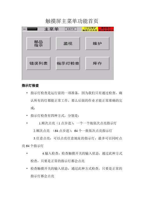
触摸屏主菜单功能首页指示灯检查•指示灯检查是运行前的一项准备,因为我们只有通过检查,确认所有的灯都能正常工作,那么后面的作业才能正常准确的完成;•指示灯检查有四种方式,分别是:• 1.顺次点亮(1点步进):一个一个地依次点亮指示灯2.顺次点亮(64点步进):64个一批依次点亮指示灯3.任意点亮:可以点亮任意地址的指示灯;最多可以同时点亮64个指示灯• 4.输入检查:检查触摸开关的输入状态,通过此种方式检查,只要是正常的指示灯都会点亮•检查触摸开关的输入状态,通过此种方式检查,只要是正常的指示灯都会点亮在指示灯检查时也可以同时检查三色灯和蜂鸣器是否正常部品作业指示画面•通过此画面,我们可以知道当前作业的序列号以及车种等相关信息。
而由该画面上面提示可知道当前系统中的一些情况,比如通信连接,是否有错误发生,是否有触摸开关失效。
•而该画面左上角01窗号处即是隐藏按钮。
该按钮功能即是强制完成功能,即无论当前作业进度如何,长按此按钮3秒或以上就会强制请求到下一条数据•在当前指示画面首页中我们可以简单的看到当前体统运行过程中的一些相关信息。
而当前指示画面有十页,根据需要,可以前进或后退查看当相关详细的具体信息。
•在所有的当前指示信息中,都只是介绍当前作业序列号的有关信息。
比如车种型号,车种颜色,内饰颜色,规格等等监视功能说明在监视功能状况下,可以了解整个IPMS系统当前运行状况,即当前缓存情况,当前料架信息,控制站信息和各功能块当前状态情况错误列表功能•当IPMS在运行过程中发生了故障的时候,就会弹出表示故障概况的故障显示对话框,同时在部品指示窗口中的故障区域里也会有“故障发生”指示,这时候应该针对该故障采取相应的措施;•如果想要了解有关故障履历或者曾经发生过的故障的详细信息,请参看故障履历窗口中的有关内容;•如果想要了解当前发生的报警信息,请参看当前发生报警窗口中的有关信息•当报警消除以后,列表中的故障信息会自动消失;并且会在窗口中的解除时间一栏中显示出该故障的解除时间;•必要的时候解除报警信息•当想要忽略所发生故障的有关内容时,可以解除该故障;当选定待解除的故障并点选故障解除按钮以后,该故障即被解除并且在解除时间一栏中显示出该故障的解除时间,若点故障解除按钮故障仍不能解除,则需联系IPMS系统管理员•触摸屏维护功能说明维护模式的切换•当我们要切换到维护模式时,这时需点住隐藏按钮(隐藏按钮即为下图勾画出的两个区域,且两个按钮要同时按住)的同时点执行按钮则进入维护模式。
触摸屏使用说明

触摸屏使用说明触摸屏使用说明1、介绍1.1 触摸屏的概述在本章节中,将详细介绍什么是触摸屏,它的基本原理以及在各种设备中的应用。
1.2 触摸屏的种类在本章节中,将常见的触摸屏种类,如电阻式触摸屏、电容式触摸屏、表面声波触摸屏等,并介绍它们的特点和适用场景。
2、触摸屏的安装2.1 触摸屏的准备工作在本章节中,将介绍触摸屏安装前的准备工作,包括检查硬件设备、连接线缆等。
2.2 触摸屏的安装步骤在本章节中,将详细描述触摸屏的安装步骤,包括固定触摸屏、连接数据线和供电线等。
3、触摸屏的操作3.1 基本操作在本章节中,将介绍触摸屏的基本操作方式,如单击、滑动、双指缩放等,并提供相应的操作指南和注意事项。
3.2 高级操作在本章节中,将介绍触摸屏的高级操作方式,如多点触控、手势识别等,并提供相应的操作指南和注意事项。
4、触摸屏的维护与保养4.1 清洁触摸屏在本章节中,将介绍如何正确清洁触摸屏,包括使用适当的清洁剂和工具等,并提供清洁的注意事项。
4.2 防护触摸屏在本章节中,将介绍如何对触摸屏进行防护,如安装保护膜、避免硬物碰撞等,并提供相应的防护建议。
5、故障排除5.1 常见故障及解决方法在本章节中,将触摸屏常见故障,并提供相应的故障排除方法和建议。
5.2 联系售后支持在本章节中,将提供联系售后支持的方式和信息,以便用户在遇到无法解决的问题时寻求帮助。
本文档涉及附件:附件1:触摸屏安装示意图附件2:触摸屏操作指南附件3:触摸屏清洁剂推荐表本文所涉及的法律名词及注释:1、版权:指对原创作品享有的法律保护权利。
2、商标:指用于区分商品或服务来源的标识,受商标法保护。
3、专利:指对新的技术、产品或制造方法的独占权利,受专利法保护。
触摸屏使用说明书
1. 前言 (2)1.1 功能介绍 (2)1.2 技术指标 (3)1.3 注意事项 (3)2. 流水线操作指南 (4)2.1 启停控制 (4)2.2 故障复位操作 (6)2.2.1单工位故障复位 (6)2.2.2 断电故障复位 (7)2.3 屏蔽单工位操作 (9)2.4 单双线控制 (9)2.5 单独工位检测操作 (10)3. 触摸屏说明 (12)3.1 控制面板按钮说明 (12)3.2 触摸屏主页 (12)3.3辅助功能键 (14)3.3.1 辅助功能键F1 (14)3.3.2 辅助功能键F2 (15)3.3.3 辅助功能键F4 (16)3.3.4 辅助功能键F6 (18)4. 工控机说明 (19)4.1 打标机操作界面 (19)4.2 监控软件wincc (19)5.常见故障及处理 (19)5.1 单工位常见机械故障及处理 (19)5.2 报警处理 (20)5.3 电感式接近开关故障处理 (21)1. 前言1.1 功能介绍如上图所示为阀门检测流水线的平面视图,标有红色开始位置为阀门的手工上件处,也是整条流水线的起点。
本瓶阀检测流水线可以实现对瓶阀的流量、低压开启气密性、高压开启气密性、高压闭合气密性、外螺纹、内螺纹通规、内螺纹止规等的精确检测,同时对检测合格的产品进行压口和打标处理,对不合格的产品根据不合格的类型进行自动分拣。
上图中,气密性检测的A线和B线是功能相同的两条线,设置A、B线主要是为了提高检测效率。
阀门检测流水线分双线、A单线、B单线三种工作模式。
默认状态为双线运行模式,即A、B线同时运行,其检测的效率为36秒/个;A单线或B单线运行模式下,检测的效率均为72秒/个。
1.2 技术指标1.主控制柜输入电源电压AC380V,最大电流20A;控制柜内部弱电电压DC24V。
2.流水线正常工作气压:0.5~0.7Mpa;高压气密性检测的高压气体压力2.5MPa,低压检测的低压气体压力0.05Mpa。
HMI操作面板使用说明
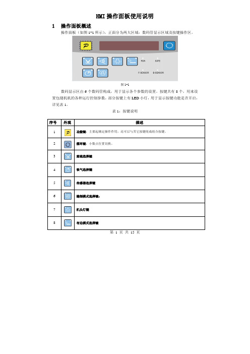
第 1 页 共 15 页HMI 操作面板使用说明1 操作面板概述操作面板(如图1-1所示),正面分为两大区域:数码管显示区域及按键操作区。
图1-1数码显示区由6个数码管构成,用于显示各个参数的设置。
按键共有8个,用来设置包缝机机的各种运行控制参数,部分按键上有LED 小灯,用于显示按键功能是否开启,详见表1。
表1:按键说明序号 外观描述1功能键:主要起确定操作作用,还可以与其它按键组成组合按键。
2 循环键:小数点位置切换。
3剪线选择键4吸气选择键5传感器选择键6缝制模式选择键:7机头灯键8布边模式选择键2用户模式定义2.1操作员模式此模式为操作面板的默认模式,操作面板上电后自动进入此模式。
进入此模式,6个数码管上的小数点位会两个相连的数码管小数点移动显示(屏幕显示),表示HMI处于空闲状态。
在执行任何操作的时候,如果长时间不按按键的话,HMI会自动切换到空闲状态,前一执行的操作将不会被执行!2.1.1全自动/半自动/全手工模式设置:全自动模式:按5键,再按下6键,两个无先后顺序。
5键灯亮,6键灯亮。
半自动模式:5键灯亮,6键灯灭。
全手工模式:5键灯灭,6键灯灭。
2.1.2剪线模式设置:。
当3按键上面两个LED灯都不点亮的时候,表示没有剪线;当3按键左上方LED灯点亮,右上方不亮的时候,表示前剪线;当3按键左上方LED灯不亮,右上方点亮的时候,表示后剪线;当3按键左上方、右上方LED灯都点亮的时候,表示前后均剪线。
2.1.3吸气模式设置:。
当4按键上面两个LED灯都不点亮的时候,表示没有吸气;当4按键左上方LED灯点亮,右上方不亮的时候,表示前吸气;当4按键左上方LED灯不亮,右上方点亮的时候,表示后吸气;第 2 页共 15 页当4按键左上方、右上方LED灯都点亮的时候,表示前后均吸气。
2.1.4机头灯设置:当按下7后,键角LED灯会亮,机头灯点亮。
再按一下键左上角LED灯会熄灭,机头灯灭。
2.1.5布边模式设置:当8按键上面两个LED灯都不点亮的时候,表示没有拖布;当8按键左上方LED灯点亮,右上方不亮的时候,表示前拖布;当8按键左上方LED灯不亮,右上方点亮的时候,表示后拖布;当8按键左上方、右上方LED灯都点亮的时候,表示前后均拖布。
触摸屏操作说明
触摸屏操作说明一、面板说明1、停按钮开关2、触模式人机界面二、电路保护本机组采用可编程控制器和人机界面等高科技产品控制运行,能够显示各种运行参数,在电路保护上,如出现故障,人机界面将显示出故障原因。
1、水泵开启信号(CWFS)在PLC中进行联锁编辑,水泵不运行,压缩机组不运行。
2、QF为断路器对机组提供短路和过载保护,若发生短路或压缩机过载,则切断机组供电。
3、OW为压缩机油位保护,若压缩机电机油位低于额定值,停压缩机,PLC上故障灯亮,人机界面故障显示。
4、HP、LP为制冷系统压力保护,若系统高压过载或低压过低,停压缩机,PLC上故障灯亮,人机界面故障显示。
5、SA为警停开关,当机组遇到紧急情况时,可按下此钮,机组控制断电停机。
6、INT69Y为智能保护器,对机组提供相序保护、超温保护及排气保护,若发生相序错误、或缺相,温升过高,压缩机不工作,PLC上故障灯亮,人机界面故障显示。
7、OP为压缩机油压差保护,若压缩机电机油压超过设定值,停压缩机,PLC上相应指示灯灭,人机界面故障显示。
8、另外,还为用户预留了其它保护的接线端子,如正压风压力过低,开机信号接入点、故障信号接入点等。
三、开机准备检查电源进线是否正确。
1、2、检查输入点是否正确,PLC上相应的输入点对应灯应亮。
3、检查接线是否松动,若有松动,则需拧紧。
4、检查警停开关是否打开。
5、检查人机界面(触摸屏)与PLC之间的传输线是否连接好。
6、机组开机前,应先通电6小时。
四、开机操作本机组采用人机界面,使用触摸屏进行操作,所有操作在人机界面上均有中文提示,按照中文提示依次进行操作。
1、在人机界面电源接通以后,在人机操作界面上进行控制方式的选择。
2、手动控制开机手动控制开机为调试人员时用,用户不得随意使用手动开机。
3、自动控制机组运行根据人机界面的提示进入自动控制状态进行温度的设定之后,开启运行机组的复合式开关,机组自动开始运行进入到计时。
五、触摸屏操作说明1、人机界面通电以后,首先是机组的主屏显示,如图1性能特点等。
ITO触摸屏原理及基础知识
ITO触摸屏原理及基础知识2008-08-01 22:41目前主要有几种类型的触摸屏,它们分别是:电阻式(双层),表面电容式和感应电容式,表面声波式,红外式,以及弯曲波式、有源数字转换器式和光学成像式。
它们又可以分为两类,一类需要ITO,比如前三种触摸屏,另一类的结构中不需要ITO, 比如后几种屏。
触摸屏在我们身边已经随处可见了,在PDA等个人便携式设备领域中,触摸屏节省了空间便于携带,还有更好的人机交互性。
目前主要有几种类型的触摸屏,它们分别是:电阻式(双层),表面电容式和感应电容式,表面声波式,红外式,以及弯曲波式、有源数字转换器式和光学成像式。
它们又可以分为两类,一类需要ITO,比如前三种触摸屏,另一类的结构中不需要ITO, 比如后几种屏。
目前市场上,使用ITO材料的电阻式触摸屏和电容式触摸屏应用最为广泛。
电阻式触摸屏ITO 是铟锡氧化物的英文缩写,它是一种透明的导电体。
通过调整铟和锡的比例,沉积方法,氧化程度以及晶粒的大小可以调整这种物质的性能。
薄的ITO材料透明性好,但是阻抗高;厚的ITO材料阻抗低,但是透明性会变差。
在PET聚脂薄膜上沉积时,反应温度要下降到150度以下,这会导致ITO氧化不完全,之后的应用中ITO会暴露在空气或空气隔层里,它单位面积阻抗因为自氧化而随时间变化。
这使得电阻式触摸屏需要经常校正。
图一是电阻触摸屏的一个侧面剖视图。
手指触摸的表面是一个硬涂层,用以保护下面的PET层。
PET 层是很薄的有弹性的PET薄膜,当表面被触摸时它会向下弯曲,并使得下面的两层ITO涂层能够相互接触并在该点连通电路。
两个ITO层之间是约千分之一英寸厚的一些隔离支点使两层分开。
最下面是一个透明的硬底层用来支撑上面的结构,通常是玻璃或者塑料。
电阻触摸屏的多层结构会导致很大的光损失,对于手持设备通常需要加大背光源来弥补透光性不好的问题,但这样也会增加电池的消耗。
电阻式触摸屏的优点是它的屏和控制系统都比较便宜,反应灵敏度也很好。
15英寸电容触摸屏显示器用户手册说明书

TCM006Table of ContentsChapter I: Overview21.1 Safety Information21.2 Electromagnetic Compatibility Statement3 Chapter II: Installation Guide32.1 Appearance of TCM006 Touch Screen Monitor:42.2 The Rear Panel I/O Signs and Description:4Key Function:5 Chapter III: Instructions for Installation63.1 Touch Screen Driver Installation:6 Chapter IV: Common Problems and Solutions15 No display on the screen15 Characters look too dark or too light15 The monitor display needs to be adjusted15 The text on the screen is unclear or blurred15 Touch panel doesn’t respond15Chapter I: OverviewDear Valued Customer,Thank you for purchasing 3nStar products. We are committed to continuously maintaining the product quality and providing better after-sales service. In order to take full advantage of our devices, we recommend reading through this manual before the driver installation.1.1 Safety Information●TCM006 is fully compliant with the relevant requirements of the national standardGB/4943-2001 IT equipment security.●Make sure the electricity meets the power requirements (such as voltage, frequency)before installation and power outlet are properly grounded.●Lightning may damage the product. Unplug the network cable, power cable or anyother conductors during lightning storms.●Do not unplug the components and connections (except for the USB device) when thepower is on.●Do not open the cabinet of the product by a non-professional technician.●Do not leave any item or liquid inside the product. Do not place any objects into theventilation holes, it may cause short-circuit of the internal components and may causefire or electric shock.●In accordance with the national standards GB/T9813-2000 microcomputers generalspecification, after the computer is below the temperature of 10 ° C, place the machinein room temperature (10-35 ° C) conditions for more than two hours to avoid damagefrom low temperature. In the meantime, please do not remove the casing but allow thecomputer to restore the natural temperature. Avoid heating the unit up too fast becausethe computer may generate frost and condensation that might damage the electricalcomponents.●This unit is in strict compliance with the electrical appliance standards.●Safe use voltage range: 100V ~ 240V & 50Hz/60Hz.●Verify that the power outlet is available to connect to a reliable ground circuit.●Keep the device clean, dry, away from dust, moisture and direct sunlight.●Do not share the same power outlet with high-power consumption electrical devices.Keep distance from high level magnetic interference.●Turn off the power to the monitor after use to extend useful life.●Do not use sharp points with, draw on or cut the touch screen to ensure a normal lifecycle.●Switch off the power supply before plugging in or unplugging the communication cableor connecting to an external device.●Unauthorized and unqualified technicians should not open the machine, or they assumeall risks and may damage the unit.When any of the following occurs:●Liquid penetrates into the body of the monitor●Monitor is accidentally damaged●Monitor produces a burning smell●Monitor display is suddenly abnormal or distortedDisconnect the power supply immediately, unplug the power cord and contact a qualified service technician to service the unit.1.2 Electromagnetic Compatibility Statement●TCM006 is fully compliant with the relevant requirements of the national standards(GB/9254-1998) “The limits and measurement methods of radio disturbancecharacteristics of information technology equipment” for Class B products.●TCM006 is fully compliant with the relevant requirements of the People's Republic ofChina’s national standards of (GB/17625.1-2003) “Electromagnetic CompatibilityLimits for harmonic current emission limits” for Class B products.Chapter II: Installation Guide2.1 Appearance of TCM006 Touch Screen Monitor:2.2 The Rear Panel I/O Signs and Description:A row of the external device connection interface is located at the rear bottom panel of the monitor, such as: power outlet, Line in, VGA and USB interface, detailed as follows:●TOUCH USB: this is connected to PC’s USB Ports, used for touch function●DC In: 12V DC in, power supply for the touch monitor.●VGA In: This is connected to PC’s VGA output port.Key Function:●Menu: Press this button to get a pop-up OSD menu, and enter the menu item (function)highlighted while the OSD menu is activated.●ON/OFF: Turn the LCD power on and off. When the power is on, the light is showinggreen, stand by will be red●UP: Press this button to increase the value of the function selected or move to theprevious function●Down: Press this button to decrease the value of the function selected or move to theprevious function●AUTO/EXIT: Press this button to apply the monitor setting automatically and Exit theOSD menuTCM006 touch screen monitor uses a manual handle design which is able to be adjusted within the range of 0 degrees to 90 degrees to make operation and viewing more comfortable.Chapter III: Instructions for Installation3.1 Touch Screen Driver Installation:Step 1: Open the installer directory on the CD, double-click “Setup.exe”Step 2: Installation begins as the following figure shows. Click Next to proceed to the next step.Step 3: Installation in progressStep 4: Click “Install PS/2 interface driver” and click “Next” to proceed with the installation.Step 5: For the touch interface RS232, click “Install RS232 interface driver” and click “Next” to proceed with the installation.Step 6: When choosing the calibrations, select NONE and click “Next” to proceed with the installation.Step 7: When installing USB touch, please connect the USB controller and USB cable.Step 8: When using two or more touch screens, please select “Support multi- monitor system”.Step 9: Select the destination location to store the driver. The default path isC: \ Program Files \ eGalaxtouch. Use the default path here and click “Next” toproceed with the installation.Click “Next” to proceed with the installation.Step 10: Select the option to create a desktop shortcut icon.After installing the driver successfully, identify the USB controller card and RS232 control card as the following two figures show:Related touch function settingTouch device line testTouch screen settingTouch device edge correction setting Touch device hardware information displayChapter IV: Common Problems and SolutionsNo display on the screen●Power saving mode is on, press any key on the keyboard or move the mouseto activate.●The pins of the VGA cable connector are bent or lost contact to the VGAinterface. Change the VGA cable. If the problem still persists, bring the unit to an authorized service provider.Characters look too dark or too lightUse the OSD Menu to adjust the brightness.The monitor display needs to be adjustedThe resolution frequency should be changed.The text on the screen is unclear or blurredMake sure the resolution or refresh rate are compatible with the Display Mode. Touch panel doesn’t respondMake sure the touch screen driver is installed properly into your PC system and calibration is done.Thank you very much for using this 3nStar product.。
- 1、下载文档前请自行甄别文档内容的完整性,平台不提供额外的编辑、内容补充、找答案等附加服务。
- 2、"仅部分预览"的文档,不可在线预览部分如存在完整性等问题,可反馈申请退款(可完整预览的文档不适用该条件!)。
- 3、如文档侵犯您的权益,请联系客服反馈,我们会尽快为您处理(人工客服工作时间:9:00-18:30)。
Application ReportSLAA491B–April2011–Revised July2011Getting Started With Capacitive Touch Software LibraryMSP430ABSTRACTThe objective of this document is to explain the process of getting started with the Capacitive Touch Software Library.There are multiple ways to perform capacitive touch sensing with the MSP430™.This document gives an overview of the methods available,the applicable target platforms and example projects to start development.Example projects accompanied with a step-by-step walkthrough of library configuration with the Capacitive Touch BoosterPack based on the LaunchPad™Value Line Development Kit(MSP-EXP430G2)using the MSP430G2452are also presented.Software collateral and Example Project Files for Code Composer Studio™4.2.1and IAR Embedded Workbench™5.20can be downloaded from the MSP430Capacitive Touch Sensing Landing Page.Contents1Overview of Capacitive Touch Sensing Methods (2)2Example Projects (3)3References (16)Appendix A Current Measurements (17)List of Figures1Library Architecture (2)2Capacitive Touch BoosterPack:Element Port/Pin Assignment (4)3File and Directory Structure (9)4Code Composer Studio New Project Wizard–Target MCU Device Selection Step (10)5Code Composer Studio Project Properties Window–Predefined/Preprocessor Symbols (11)6Code Composer Studio Project Properties Window–Enable GCC Extensions Option (12)7Code Composer Studio Project Explorer View(C/C++Tab) (12)8Code Composer Studio Project Properties Window–Include Options (13)9IAR Project Options–Target Device (14)10IAR Project Options–Preprocessor Options (14)11IAR Project Options–FET Debugger (15)12IAR Project Explorer View (15)List of Tables1Overview of Capacitive Touch Measurement Methods(Supported by the Library) (3)2Description of the Example Projects (10)3Current Measurements for Example Projects (17)MSP430,LaunchPad,Code Composer Studio are trademarks of Texas Instruments.IAR Embedded Workbench is a trademark of IAR Systems AB.All other trademarks are the property of their respective owners.………Overview of Capacitive Touch Sensing Methods 1Overview of Capacitive Touch Sensing MethodsThere are several methods of performing capacitive touch sensing using the MSP430family of devices.A combination of different peripheral sets across different device families can be used to measure thecapacitive touch response from a sensor.Figure1breaks down the architecture of the Capacitive Touch Software Library.The top layer is theApplication Layer that has user-defined application code.The layers underneath belong to the Capacitive Touch Library.The bottom layer is the Hardware Peripheral Layer that contains low-level functions forperipheral configurations.The Hardware Abstraction Layer(HAL)has functions for implementing sensing techniques using different peripheral sets.The next layer up is the Capacitive Touch Layer that contains high-level abstract functions for implementing sensor structures such as buttons,wheels and sliders.Note that the level of abstraction increases from left to right,where the Raw simply outputs raw counts versus the Wheel that outputs touch position.Figure1.Library Architecture2Getting Started With Capacitive Touch Software Library SLAA491B–April2011–Revised July2011 Example Projects Table1lists the different methods available.The Method Name column on the left hand side indicates the HAL Description Name as implemented in the Capacitive Touch Library.Details on each method andimplementation can be found in the Capacitive Touch Library Programmer's Guide(SLAA490)[1].Table1.Overview of Capacitive Touch Measurement Methods(Supported by the Library) Method Name Measurement Example MSP430 (HAL description)Sensing Type Peripheral Timer Gate Timer Benefits DevicesRO_COMPAp_TA0_WDTp Relaxation Comparator TimerA0Watchdog Enables low-power MSP430F20x1Oscillator(RO)COMPA+Timer WDT+mode during MSP430F4xxmeasurements RO_PINOSC_TA0_WDTp Relaxation Pin Oscillator TimerA0Watchdog Enables low-power MSP430G2xx2Oscillator(RO)Timer WDT+Modes duringmeasurements RO_PINOSC_TA0Relaxation Pin Oscillator TimerA0Software Does not use MSP430G2xx2Oscillator(RO)counter watchdog timerresourceRO_COMPB_TA0_WDTA Relaxation Comparator TimerA0Watchdog Enables low-power CC430FxxOscillator(RO)COMPB Timer WDTA Modes duringmeasurements RO_COMPB_TA1_WDTA Relaxation Comparator TimerA1Watchdog Enables low-power MSP430F55xxOscillator(RO)COMPB Timer WDTA Modes duringmeasurements RC_PAIR_TA0RC Time Digital I/O TimerA0N/A Simple All MSP430devicesConstant(RC)and resistor Implementation fRO_PINOSC_TA0_SW Fast Relaxation Pin Oscillator Software TimerA0Fast Scan Rate MSP430G2xx2Oscillator(fRO)counterDescriptions of the RO and RC principles can be found in PCB-Based Capacitive Touch Sensing WithMSP430(SLAA363)[2]and a detailed design guide for the RC-based single touch sensor can be found in the MSP430Capacitive Single-Touch Sensor Design Guide(SLAA379)[3].2Example Projects2.1Overview of the Example ProjectsThe example project uses the Capacitive Touch BoosterPack on the LaunchPad value line development kit with the MSP430G2452MCU.The LaunchPad is a low-cost development kit with a20-pin PDIPsocket,on-board programmer and debugger,universal serial bus(USB)communication to PC,etc.[4].Along with the8KB of Flash and256B of RAM,the MSP430G2452MCU has16touch-sense enabled input/output(I/O)pins that use the pin oscillator feature aforementioned in Section1[5].WheelP2.4 (up)P2.1 (left)P2.3 (right)P2.2 (down)P2.0 (proximity)P2.5 (middle)Example Projects 2.2Overview of the Capacitive Touch BoosterPack HardwareThe capacitive touch BoosterPack is based on the pin oscillator feature and illustrates three types ofsensors:Proximity,Button and Wheel(group of buttons).Figure2shows the layout of the sensors and port/pin definition to the MSP430G2452MCU.Figure2.Capacitive Touch BoosterPack:Element Port/Pin AssignmentThere are also nine LED elements that are multiplexed to indicate touch:four on either side and one for the middle element.For details on the schematic connections and PCB layout,see the Capacitive Touch BoosterPack User’s Guide(SLAU337)[6].2.3Configuring the Software LibraryThe Capacitive Touch Software Library must be configured with the port definition,sensing method,number of elements,and other factors.These factors can be configured in structure.c source code and structure.h header files.The following steps are presented using theRO_PINOSC_TA0_WDTp_One_Button Example where the sensing method is RO_PINOSC_TA0_WDTp and the sensor structure comprises of one button(the middle element).1.Element Definition:Declare the element structure and assign the port/pin definition.Example:The middle element is mapped to P2.5(Port2/Pin5).Within the structure.c source code file://Middle Element(P2.5)const struct Element middle_element={.inputPxselRegister=(uint8_tt*)&P2SEL,.inputPxsel2Register=(uint8_t*)&P2SEL2,.inputBits=BIT5,//When using an abstracted function to measure the element//the100*(maxResponse-threshold)<0xFFFF//ie maxResponse-threshold<655.maxResponse=200+655,.threshold=200//Set threshold to zero for element characterization };Within the structure.h header file:extern const struct Element middle_element;4Getting Started With Capacitive Touch Software Library SLAA491B–April2011–Revised July2011 Example Projects NOTE:The threshold variable should be set to zero for the element characterization step.NOTE:The maxResponse variable is required to be set only for the wheel/slider implementationand is not needed for a single sensor implementation.For more details,see the CapacitiveTouch Library Programmer's Guide(SLAA490)[1]2.Sensor Structure Definition:Declare the sensor structure and define the sensing method,number ofsensor elements,the gate timer source,and the measurement window.Example:The sensor structure:•Comprised of one element(the middle element)•Sensing method is the relaxation oscillator using the pin oscillator feature•TimerA0is measurement timer;watchdog timer(WDT)is gate timerWithin the structure.c source code file://One Button Sensorconst struct Sensor one_button={.halDefinition=RO_PINOSC_TA0_WDTp,//Sensing Method.numElements=1,//#of Elements.baseOffset=0,//First element index=0//Pointer to elements.arrayPtr[0]=&middle_element,//point to middle element//Timer Information.measGateSource=GATE_WDT_ACLK,//0->SMCLK,1->ACLK.accumulationCycles=WDTp_GATE_64//64-Default};Within the structure.h header file:extern const struct Sensor one_button;3.Characterizing Element Performance:•Initialize Threshold:As mentioned in Step1,the threshold value should be initialized to zero for element characterization.•Configure the Gate Timer:This example uses the RO_PINOSC_TA0_WDTp method with the Watchdog timer used as the Gate Timer.The Gate Time will have a direct impact on the noiseimmunity,touch sensitivity,power consumption and overall performance of the sensor.–Adjust the Gate Timer Source(measGateSource)to source the WDT from eitherlow-frequency ACLK or high-frequency SMCLK.–Adjust the measurement window(accumulationCycles)to select between different WDT intervals.Example Projects Within the structure.c source code file://One Button Sensorconst struct Sensor one_button={.halDefinition=RO_PINOSC_TA0_WDTp,//Sensing Method.numElements=1,//#of Elements.baseOffset=0,//First element index=0//Pointer to elements.arrayPtr[0]=&middle_element,//point to middle element//Timer Information//Select Gate Timer Source for Watchdog Timer//.measGateSource=GATE_WDT_SMCLK,//SMCLK?.measGateSource=GATE_WDT_ACLK,//ACLK?//Select Measurement Window timeframe by selecting//the Watchdog Timer Input Clock divider setting//.accumulationCycles=WDTp_GATE_32768//32768//.accumulationCycles=WDTp_GATE_8192//8192//.accumulationCycles=WDTp_GATE_512//512.accumulationCycles=WDTp_GATE_64//64};•Setup the characterization function:Once the Gate Time has been configured,the main() function should call the Baseline tracking function and monitor the counts returned from theTI_CAPT_Custom()function.This action can be accomplished by un-commenting or declaring thefollowing compiler directive in the main.c source code file.//Uncomment to have this compiler directive run characterization functions only#define ELEMENT_CHARACTERIZATION_MODEWhen the compiler directive ELEMENT_CHARACTERIZATION_MODE is defined,the following codefor element characterization is compiled within main.c source code file.//Within the application layer source code file:main.c#include"CTS_Layer.h"//Delta Counts returned from the API function for the sensor during characterizationunsigned int dCnt;void main(void){WDTCTL=WDTPW+WDTHOLD;//Stop watchdog timer................................//Set up system clocksBCSCTL3|=LFXT1S_2;//LFXT1=VLO Clock SourceP1OUT=0x00;//Drive all Port1pins low................................//Initialize PortsP2DIR=0xFF;//Configure all Port2pins outputs//Initialize Baseline measurementTI_CAPT_Init_Baseline(&one_button,5);while(1){//Get the raw delta counts for element characterizationTI_CAPT_Custom(&one_button,&dCnt);__no_operation();//Set breakpoint here}}6Getting Started With Capacitive Touch Software Library SLAA491B–April2011–Revised July2011 Example Projects •Getting the Characterization Delta Counts:To get the delta counts for element characterization, set a breakpoint on the NOP following the TI_CAPT_Custom()function and add the variable dCntto the Watch window.Run the program several times and record the value for the following twocases:–No Touch:No finger is touching the middle element and no conductive object in the immediate vicinity of the sensor.This is effectively characterizing the background noise.Record themaximum value of dCnt in this scenario as noTouchCnt.–Touch:A finger is touching the middle element or some conductive object is in the immediate vicinity of the sensor.This is effectively characterizing the touch response sensitivity.Recordthe minimum value of dCnt in this scenario as TouchCnt.4.Setting the Threshold Value:The threshold value should nominally be set to the middle of the range:threshold=(TouchCnt-noTouchCnt)/2.The threshold can be set higher or lower to increase noiseimmunity or increase sensitivity.NOTE:Setting a threshold value too low increases the probability of false triggers(and make itsusceptible to noise).Setting a threshold value too high causes the sensor to not recognizethe presence of a conductive object.Once the threshold value is calculated,the respective element structure should be updated with thenew value.For example,during the characterization process,noTouchCnt=100and TouchCnt=1000.The threshold value should be set to450.Within structure.c source code file://Middle Element(P2.5)const struct Element middle_element={.inputPxselRegister=(uint8_t*)&P2SEL,.inputPxsel2Register=(uint8_t*)&P2SEL2,.inputBits=BIT5,//When using an abstracted function to measure the element//the100*(maxResponse-threshold)<655.maxResponse=450+655,.threshold=450//Update the threshold after characterization NOTE:Steps3and4may have to be attempted multiple times to determine the appropriate gatetime for the PCB layout,neighboring element structures and application noise levels.This isan iterative fine-tuning process.ing API calls to achieve higher levels of abstraction:The library provides several API calls thatcan abstract out all of the inner workings,such as baseline tracking,rate of change,etc.These callsprovide the advantage of having streamlined code in the Application Layer.NOTE:All of the measurement API functions(with the exception of the TI_CAPT_RAW()function)update the baseline tracking.The TI_CAPT_Update_Baseline()and/orTI_CAPT_Init_Baseline()functions should be used if the sensor is not measured for a longperiod of time(during which drift over time in supply voltage,temperature,or environmentconditions may have occurred).Example Projects •Objective of the Sample Application:To detect touch of one button(middle element),the application calls the TI_CAPT_Button()API function.The function returns logic one or zero toindicate if there is a valid touch or not.This information is used to turn on the center LED on theCapacitive Touch BoosterPack.The LED serves as a visual indicator of center button touch.Between consecutive polling calls,the MSP430is placed into low-power mode(LPM3).Timer A0isused to implement a delay timeout feature to wake up from LPM3into Active Mode.This delay isprogrammable and can be adjusted in main.c source code file.#define DELAY5000//Timer delay timeout count-5000*0.1msec=500msec•Configuring the Sample Application:In main.c source code file,the compiler directive ELEMENT_CHARACTERIZATION_MODE should be commented out so that the application code(rather than characterization code)is compiled.//Comment to have this compiler directive run example application//#define ELEMENT_CHARACTERIZATION_MODE2.4Example ProjectsFigure3shows the directory and the file structure for the associated files that are available for download with this application report.•CCS:Contains Project folders and files for Code Composer Studio IDE•IAR:Contains Project folders and files for IAR Embedded Workbench•Library:Contains the Capacitive Touch Library Files(HAL and Application Layer)•Examples:Each folder within has code examples that provide a starting point for developing applications on different MSP430families using various implementations.(Sample Application andstructure definition files).The high-level API calls such as TI_CAPT_Custom(),TI_CAPT_Buttons(),etc.,consume more Flashmemory space but abstract the inner workings such as Baseline Tracking,Rate of Updates,Direction of Interest,etc.,from the Application layer.The resulting Application Layer is compact and any updates to the HAL or Layer functions do not require any modifications to the application code.The low-level API calls such as TI_CAPT_Raw()can be used to achieve lower Flash memory codefootprint but features such as baseline tracking will have to be implemented manually in the application code.This scenario can possess an advantage for very low-memory devices and yet obtain verylow-levels of power consumption.8Getting Started With Capacitive Touch Software Library SLAA491B–April2011–Revised July2011SLAC489+- - - Documentation+- - - Getting_Started_Projects||+- - - Library| CTS_HAL.c | CTS_HAL.h | CTS_Layer.c | CTS_Layer.h |+- - - Examples+- - - - -RO_PAIR_TA0| main.c | structure.c | structure.h |+- - - RO_COMPAp_TA0_WDTp | main.c | structure.c | structure.h |+- - - RO_COMPB_TA1_WDTA | main.c | structure.c | structure.h +- - - . . .+- - - . . .+- - - SourceRO_PINOSC_TA0_WDTp_One_Buttonmain.c structure.c structure.h +--- CCS| +--- RO_PINOSC_TA0_WDTp_One Button | +--- ...+--- IAR+--- RO_PINOSC_TA0_WDTp_One Button +--- ...+---+--- Example ProjectsFigure 3.File and Directory StructureExample Projects Table2.Description of the Example ProjectsAPI Sensor Flash RAM Example Name Level Structure Description(bytes)(1)(bytes)(1)(2) RO_PINOSC_TA0_WDTp_Low Button(Middle Element)Turn the center LED on or off59618One_Button_Compact based on middle elementtouchRO_PINOSC_TA0_WDTp_High Button(Middle Element)Turn the center LED on or off190014One_Button based on middle elementtouchRO_PINOSC_TA0_WDTp_High Proximity Sensor Turn the center LED on or off190814Proximity_Sensor based on proximity sensordetectionRO_PINOSC_TA0_WDTp_High Wheel(Group of Five Turn the center LED on or off225432Wheel_Buttons Buttons)based on the five wheelbuttons(1)Code Composer Studio4.2.1IDE was used to generate the Flash and RAM memory allocation results.(2)The default boot/rts stack size(0x50~80bytes)is not included in the RAM size.2.5Project Setup in Code Composer Studio IDEThe Code Composer Studio(CCS)Integrated Development Environment(IDE)can be used to build,download,and debug the project source code.NOTE:Code Composer Studio v4.2.1with MSP430Code Generation Tools v3.3.3was used tocreate the example projects.1.Initiate Code Composer Studio,File→New CCS Project,and follow the steps through the New ProjectWizard to create a project for an example.For more information on new project setup,please refer tothe Code Composer Studio v4.2User's Guide for MSP430User's Guide(SLAU157)[7].2.Select the appropriate target MCU device.In the case of the Capacitive Touch BoosterPack,select theMSP430G2452MCU(as shown in Figure4).Figure4.Code Composer Studio New Project Wizard–Target MCU Device Selection Step10Getting Started With Capacitive Touch Software Library SLAA491B–April2011–Revised July2011 Example Projects3.Ensure that the preprocessor/predefined symbol in the Project Build Options matches the target MCUdevice(as displayed in Figure5).Figure5.Code Composer Studio Project Properties Window–Predefined/Preprocessor Symbols11 SLAA491B–April2011–Revised July2011Getting Started With Capacitive Touch Software Library Submit Documentation FeedbackCopyright©2011,Texas Instruments IncorporatedExample Projects 4.Enable the GCC Extensions for the Project Build(as shown in Figure6).•Go to Project→Properties to bring up the Project properties dialog.•On left side,select C/C++Build.•On right side,under Configuration Settings,select the Tab Tool Settings→MSP430Compiler→Language Options→Enable Support for GCC extensions(--gcc).Figure6.Code Composer Studio Project Properties Window–Enable GCC Extensions Option5.Link the Capacitive Touch Library(HAL and Layer)and the Example Project files(Main and Structure)to the project:Project→Link Files to Active Project.For directory structure and file path,seeSection2.3.The Project configuration should look similar to Figure7.Figure7.Code Composer Studio Project Explorer View(C/C++Tab)12Getting Started With Capacitive Touch Software Library SLAA491B–April2011–Revised July2011Submit Documentation FeedbackCopyright©2011,Texas Instruments Incorporated Example Projects6.Add the path of the directories to the Include Path Option(as shown in Figure8).Figure8.Code Composer Studio Project Properties Window–Include Options7.Download and debug the example project:Target→Debug Active Project.13 SLAA491B–April2011–Revised July2011Getting Started With Capacitive Touch Software Library Submit Documentation FeedbackCopyright©2011,Texas Instruments IncorporatedExample Projects 2.6Project Setup in IAR Embedded Workbench IDEThe IAR Embedded Workbench(IAR)Integrated Development Environment(IDE)can be used to build, download and debug the project source code.NOTE:IAR Embedded Workbench6.0with MSP430v5.20was used to create the exampleprojects.1.Initiate IAR,Project→Create New Project,and follow through the steps of giving a new project namewith MSP430to create a new project.For more information on new project setup,see the IAREmbedded Workbench Version3+for MSP430User's Guide(SLAU138)[8].2.Select the appropriate target MCU device,Project→Options,General Options and Target Tab.In thecase of the Capacitive Touch BoosterPack,select the MSP430G2452MCU(as shown in Figure9).Figure9.IAR Project Options–Target Device3.Ensure that the preprocessor/predefined symbol in the Project Options→C/C++Compiler matchesthe target MCU device(as displayed in Figure10).Add the path of the directories to the Additionalinclude directories input box.Figure10.IAR Project Options–Preprocessor Options14Getting Started With Capacitive Touch Software Library SLAA491B–April2011–Revised July2011Submit Documentation FeedbackCopyright©2011,Texas Instruments Incorporated Example Projects4.Select FET Debugger as the Debugger option to download and debug the example project(as shownin Figure11).Figure11.IAR Project Options–FET Debugger5.Add the Capacitive Touch Library(HAL and Layer)and the Example Project files(Main and Structure)to the project:Project→Add Files.The Project configuration should look similar to Figure12.Figure12.IAR Project Explorer View6.Download and debug the example project:Project→Download and Debug.15 SLAA491B–April2011–Revised July2011Getting Started With Capacitive Touch Software Library Submit Documentation FeedbackCopyright©2011,Texas Instruments IncorporatedReferences 3References1.Capacitive Touch Library Programmer's Guide(SLAA490)2.PCB-Based Capacitive Touch Sensing With MSP430(SLAA363)3.MSP430Capacitive Single-Touch Sensor Design Guide(SLAA379)4.MSP-EXP430G2LaunchPad Experimenter Board User’s Guide(SLAU318)5.MSP430G2x52,MSP430Gx12Mixed Signal Microcontroller Data Sheet(SLAS722)6.Capacitive Touch BoosterPack User’s Guide(SLAU337)7.Code Composer Studio v4.2User's Guide for MSP430User's Guide(SLAU157)8.IAR Embedded Workbench Version3+for MSP430User's Guide(SLAU138)16Getting Started With Capacitive Touch Software Library SLAA491B–April2011–Revised July2011Submit Documentation FeedbackCopyright©2011,Texas Instruments IncorporatedAppendix A Current MeasurementsThe current measurements for the example projects are presented in Table3.Note that thesemeasurements represent typical values(averaged)only.Table3.Current Measurements for Example ProjectsExample Name Configuration Voltage Current Range RO_PINOSC_TA0_WDTp_One Middle Element Button 3.3V 2.4µA Touch One_Button_CompactScan Time=500msec 3.0V 2.0µAWDT source=ACLK/64 2.5V 1.4µAACLK=VLO(~12kHz) 1.8V0.9µAGate Time~5.3msec/elementRO_PINOSC_TA0_WDTp_One Middle Element Button 3.3V 2.6µA Touch One_ButtonScan Time=500msec 3.0V 2.1µAWDT source=ACLK/64 2.5V 1.7µAACLK=VLO(~12kHz) 1.8V1µAGate Time~5.3msec/elementRO_PINOSC_TA0_WDTp_STRUCTURE_CONFIG_0(1) 3.3V 2.5µA 1.5cm Proximity_SensorScan Time=500msec 3.0V2µA1cmWDT source=ACLK/64 2.5V 1.5µA0.5cmACLK=VLO(~12kHz) 1.8V 1.1µA TouchGate Time~5.3msec/elementRO_PINOSC_TA0_WDTp_STRUCTURE_CONFIG_1(1) 3.3V9.5µA 2.5cm Proximity_SensorScan Time=500msec 3.0V8µA2cmWDT source=ACLK/512 2.5V6µA 1.8cmACLK=VLO(~12kHz) 1.8V3µA 1.5cmGate Time~42.6msec/elementRO_PINOSC_TA0_WDTp_STRUCTURE_CONFIG_2(1) 3.3V20µA 3.5cm Proximity_SensorScan Time=500msec 3.0V17.5µA3cmWDT source=SMCLK/8192 2.5V14µA 2.8cmSMCLK=DCO(~1MHz) 1.8V9µA 2.5cmGate Time~65.5msec/elementRO_PINOSC_TA0_WDTp_Four Wheel Buttons+ 3.3V8.5µA Touch Wheel_ButtonsOne Middle Element Button 3.0V7µAScan Time=500msec 2.5V 4.8µAWDT source=ACLK/64 1.8V 2.6µAACLK=VLO(~12kHz)Gate Time~5.3msec/element(1)The compiler directive for the structure configuration should be defined at the top of structure.c source file.Current Measurement Setup:•On the LaunchPad,remove all Jumpers on J3:V,TXD,RXD,RST and TEST.CC•On the LaunchPad,remove resistor R34,the pull-up resistor on P1.3and pushbutton switch S2.NOTE:R34removal is necessary for low-current measurements.•If a pull-up resistor is required,configure the Port registers on P1.3to use the internal on-chip pull-up resistors.17 SLAA491B–April2011–Revised July2011Getting Started With Capacitive Touch Software Library Submit Documentation FeedbackCopyright©2011,Texas Instruments IncorporatedIMPORTANT NOTICETexas Instruments Incorporated and its subsidiaries(TI)reserve the right to make corrections,modifications,enhancements,improvements, and other changes to its products and services at any time and to discontinue any product or service without notice.Customers should obtain the latest relevant information before placing orders and should verify that such information is current and complete.All products are sold subject to TI’s terms and conditions of sale supplied at the time of order acknowledgment.TI warrants performance of its hardware products to the specifications applicable at the time of sale in accordance with TI’s standard warranty.Testing and other quality control techniques are used to the extent TI deems necessary to support this warranty.Except where mandated by government requirements,testing of all parameters of each product is not necessarily performed.TI assumes no liability for applications assistance or customer product design.Customers are responsible for their products and applications using TI components.To minimize the risks associated with customer products and applications,customers should provide adequate design and operating safeguards.TI does not warrant or represent that any license,either express or implied,is granted under any TI patent right,copyright,mask work right, or other TI intellectual property right relating to any combination,machine,or process in which TI products or services are rmation published by TI regarding third-party products or services does not constitute a license from TI to use such products or services or a warranty or endorsement e of such information may require a license from a third party under the patents or other intellectual property of the third party,or a license from TI under the patents or other intellectual property of TI.Reproduction of TI information in TI data books or data sheets is permissible only if reproduction is without alteration and is accompanied by all associated warranties,conditions,limitations,and notices.Reproduction of this information with alteration is an unfair and deceptive business practice.TI is not responsible or liable for such altered rmation of third parties may be subject to additional restrictions.Resale of TI products or services with statements different from or beyond the parameters stated by TI for that product or service voids all express and any implied warranties for the associated TI product or service and is an unfair and deceptive business practice.TI is not responsible or liable for any such statements.TI products are not authorized for use in safety-critical applications(such as life support)where a failure of the TI product would reasonably be expected to cause severe personal injury or death,unless officers of the parties have executed an agreement specifically governing such use.Buyers represent that they have all necessary expertise in the safety and regulatory ramifications of their applications,and acknowledge and agree that they are solely responsible for all legal,regulatory and safety-related requirements concerning their products and any use of TI products in such safety-critical applications,notwithstanding any applications-related information or support that may be provided by TI.Further,Buyers must fully indemnify TI and its representatives against any damages arising out of the use of TI products in such safety-critical applications.TI products are neither designed nor intended for use in military/aerospace applications or environments unless the TI products are specifically designated by TI as military-grade or"enhanced plastic."Only products designated by TI as military-grade meet military specifications.Buyers acknowledge and agree that any such use of TI products which TI has not designated as military-grade is solely at the Buyer's risk,and that they are solely responsible for compliance with all legal and regulatory requirements in connection with such use. TI products are neither designed nor intended for use in automotive applications or environments unless the specific TI products are designated by TI as compliant with ISO/TS16949requirements.Buyers acknowledge and agree that,if they use any non-designated products in automotive applications,TI will not be responsible for any failure to meet such requirements.Following are URLs where you can obtain information on other Texas Instruments products and application solutions:Products ApplicationsAudio /audio Communications and Telecom /communicationsAmplifiers Computers and Peripherals /computersData Converters Consumer Electronics /consumer-appsDLP®Products Energy and Lighting /energyDSP Industrial /industrialClocks and Timers /clocks Medical /medicalInterface Security /securityLogic Space,Avionics and Defense /space-avionics-defense Power Mgmt Transportation and /automotiveAutomotiveMicrocontrollers Video and Imaging /videoRFID Wireless /wireless-appsRF/IF and ZigBee®Solutions /lprfTI E2E Community Home Page Mailing Address:Texas Instruments,Post Office Box655303,Dallas,Texas75265Copyright©2011,Texas Instruments Incorporated。
