音频处理器说明书
XTA DP226 音频处理器中文说明书

DP226 快 速 参 考若要对某一声道进行操作,可按该声道的 ‘GAIN’ 键。
第一次按键将使显示屏上出现增益屏幕。
用 ‘BACK’ 键和 ‘NEXT’ 键可使该声道的参数在显示屏上滚动。
(如果再按一次 ‘GAIN’ 键,可以调出上一次调整后的参数。
再按一次键将返回默认屏幕。
)若要进入菜单,可按 ‘MENU’ 键。
用 ‘BACK’ 键和 ‘NEXT’ 键寻找所需的子菜单,然后按 ‘ENTER’ 键进入选中的子菜单。
然后可用 ‘BACK’ 键和‘NEXT’ 键选择菜单项,用 ‘ENTER’ 键确认。
菜单:输入记忆子菜单:用于存贮和调出输入均衡、输入增益和基础延时等参数。
也用于存 贮和调出送往或来自 PC 卡的记忆数据。
输入设置子菜单:用于将各路输入均衡联动,或使该路输入呈平坦响应。
X-over 子菜单:用于存贮及调出 X-over 的设置值,包括格式、输出均衡、输出延时、 输出增益和限幅器的设置。
还可用于设计一套新的 X-over 。
安 全 子 菜 单:用四位密码锁定各种设置值。
系 统 子 菜 单:用于查看本机的当前状态。
其它选项包括参数显示是 Q 值还是带宽、当前的X-Over名称 用于 激活菜单用于使参数和菜单 在屏幕上滚动从限幅器门槛 起算的电平 声道静音静音时 LED 灯点亮当前输入EQ 按此键将使屏幕上的参数 均衡器旁路按此键 退出 菜单按此键 进入菜单或确认选择LED 指示灯 此声道 正在被编辑按一次进入声道增益屏幕 再按一次可观察上一次的数据再按一次返回默认屏幕电平表是接在静音开关之前还是静音开关之后。
说明:1.X-over(输出)设置值的存贮/调出(使用‘store / recall a X-over’)与输入设置值的存贮/调出(使用‘store / recall input memory’)是相互独立的。
2.输出电平表所显示的dB 值是相对于限幅器门槛值的,输入表所显示的dB 值是相对于输入剪峰值的。
优麦-数字音频处理器-说明书V2.5
重要的安全事项(针对火灾、电击或伤害人体的指示)注意-使用该电器产品时,有以下基本的预防措施:以下包括:1.使用该产品前请详细阅读全部的安全事项;2.本产品应当接地,如果出现故障时,电流经最小的接地电阻流入大地,以减小电击;本产品的电源线和电源插头都配备安全接地,电源插头应当牢固插入适当的电源座,此电源座应当完全按当地的条例来安装和接地。
警告-接地装置连接不当会导致电击;如果你对产品是否正确接地存在疑问,请委托合格电工或维修人员检查;请不要尝试私自更改产品的电源插头,如果不适合电源插座,可委托合格电工安装适当的电源插座;3. 为了减小伤害的风险,当产品在小孩附近使用时,要严密监管;4. 请勿在湿度很大的地方使用机器,例如靠近浴缸、洗面盆、厨房水槽、湿度大的地下室或者靠近游泳池和湖泊;5. 该产品应当安装与通风良好的地方;6. 该产品必须远离热源,例如电暖炉、电热毯或者其他产生热量的产品;7. 该产品的电源类型必须符合操作知识或者产品上标明的类型;8. 该产品要配备一条两端的电源线(一段的插片长过另一端)。
这是安全装置。
如果你无法把电源插头插入电源插座,请联系电工来更换旧插座。
请勿破换电源插头的安全装置;9. 长时间不使用时,请把电源线从电源插座中拔出,从电源插座拔出电源线时,请勿拉扯电源线,应当抓住电源插头将其拔出;10. 细心护理,请勿让杂物或者液体从其缝隙掉进机器内;11. 当有下列情况时,应委托合格维修人员修理:A.电源线或电源插头已被损坏B.杂物或者液体已掉进机内C.产品已被雨淋D.产品已不能正常操作或在演出中出现明显变化E.产品已跌坏或外观损坏12. 当出现没在用户维修指南中描述的情况时,请勿尝试私自修理,应当委托合格的维修人员修理;13. 警告-勿让重物积压或踩踏电源线,切忌拉、拔或强力扭曲电源线。
请勿滥用电源线,不合格的电源线可能导致火灾或对人构成伤害。
目录重要的安全事项(针对火灾、电击或伤害人体的指示) (1)一、前言 (3)二、机器架构说明 (4)三、软件操作说明 (5)3.1 软件预览 (5)3.2 菜单栏和工具栏 (6)3.2.1文件(File) (6)3.2.2本地设置(Local Setting) (6)3.2.2设备设置(Device Setting) (7)3.3 电平显示 (12)3.4 音频前级处理模块 (12)3.4.1输入源(Input) (13)3.4.2扩展器(Gate) (14)3.4.3均衡器(EQ) (15)3.4.4压缩器(Compress) (16)3.4.5自动增益(AGC) (17)3.5 混音器模块 (18)3.6 音频后级处理模块 (19)3.6.1均衡器(EQ) (20)3.9.2延时器(Delay) (21)3.9.3 反馈抑制器(AFC) (22)3.9.4 分频器(XOVER) (23)3.9.5 限幅器(Limit) (24)3.9.6 输出增益控制(Gain) (25)3.6.6分频器(XOVER) (26)四、技术指标 (27)五、常见问题 (29)一、 前言16路矩阵功能介绍16路平衡模拟LINE/MIC(平衡/非平衡)输入,前面板双色LED指示。
音频处理器 ControlSpace ESP-88 说明书

模拟输入电压范围
0 V ~ 3.3 V (最大 5 V)
数字输入电压范围
0 V ~ 3.3 V (门限电压 = 1.6 V)
控制输出
8 路数字输出,10 kΩ 内部提升电阻至 5 V, Phoenix / Euro block 2 极,9 针,3.81 mm 定位接口
输出电压 输出电流 通讯端口
0 ~ 5V 开路电极 0.5 mA (源电流) / 10 mA 最大(灌电流) 10 Base-T (RJ-45), RS-232C (DSub 9 针,公头, DTE), RS-485 (Phoenix / Euro block 2 极,3 针)
PC 041760
4 of 8
ControlSpace® ESP-88
音频处理器
ControlSpace® Designer™ 软件
Bose® ControlSpace® Designer™ 软件是一套图形用 户界面的设计软件,用于设计和配置 ControlSpace 系统。Smart Simulation 智能仿真编程功能可以使 设计师在屏幕上观察、验证、反复测试及记录各种 ControlSpace® ESP-88 音频处理器、控制中心、区域 控制器以及通用控制信号输入的编程,与是否连接系 统硬件无关。
延时存储器
16 MByte / 72 秒 ( 64 MByte / 288 秒 使用选配 DSP 扩展卡时)
信号处理(继续)
音频延迟
610 毫秒 (模拟输入到模拟输出)
(860 毫秒,使用选配的 DSP 扩展卡时)
采样频率
48 kHz
A/D 和 D/A 转换
24 位
控制输入
8 路模拟或数字输入,5.1 kΩ 内部提升电阻至 5 V, Phoenix / Euro block 2 极,9 针、3.81 mm 定位接口
CoolAudio V1000一芯多效果数字音频处理器说明说明书

Low-Cost One-Chip Multi-Effects DSPV10001. General DescriptionWith 16 built-in reverb and multi-effects, the V1000 Digital Multi-Effects DSP delivers outstanding audioperformance in a rapid time-to-market solution at a very affordable price. Since the V1000 incorporates its own RAM and on-board effects, a complete reverb system can be designed with only the V1000, a low-cost ADC and DAC,and a simple 4-bit controller such as a rotary encoder etc.2. Features• 16 internal ROM programs consisting of effects such as multiple reverbs, echo, phaser, chorus, flanger, etc.• S erially programmable SRAM (Writeable Control Store - WCS) for program development ordynamically changing programs• Programs run at 128 instructions per word clock. (6 MIPS @ 48 khz sampling frequency)• 32k location Static Ram provides over 0.68 sec of delay at 48 kHz sampling frequency• Package outline: SOIC-16/300• ROHS compliant (PB-free)Information furnished by CoolAudio is believed to be accurateand reliable. However, no responsibility is assumed by CoolAudiofor its use, nor for any infringements of patents or other rights ofthird parties which may result from its use. No license is grantedby implication or otherwise under any patent or patent rights ofCoolAudio.Rev. 1.03.Electrical Characteristics and Operating Conditions4. Outputs (DigOut, SysClk, BitClk, WordClk)5. Inputs(DigIn, Int/Ext_, Prog0/Sdata, Prog1/SClk, Prog2, Prog3, Reset_)6.Pin Descriptions V1000Note:Int/Ext_, prog0, prog1, prog2 and prog3 are pulled up to Vdd via nominal internal 30k resistor.7.Block Diagram8.Internal ProgramsThe SCR comes with 16 internal ROM programs ready to go. By setting the chip to internal mode, the four program pins may be used to select between the different algorithms.9. Programming the RAMAlongside the 16 internal programs is an externally programmable SRAM that is easily accessible through theserial clock and data pins, by setting the chip to external mode, the SClk and SData pins become available for serial communication. Except for its external programmability, there is no functional difference between the SRAM and the internal ROMs.10.Memory Map11.LFO Coefficient WordNote:If set, the output wave form is a sawtooth with double the triangle wave’s frequency.Notes:1. Crossfade only used in saw tooth wave.2.The sinusoid generated by the LFOs is or the formula Asin(nF / M) or Acos(nF / M), where n is the time index, F/M - 2 π f/Fs, M is the maximum internal value, fit the selected frequency, and Fs is the sampling frequency.Thus the frequency limits are:f = (F/M) Fs/(2π)For triangle waves, its frequency limits are:f = Fs /(4 Max / Increment)= Fs /(4 0x7fffff/222*F/M)Sawtooth SIN Sawtooth COS Crossfade 1Crossfade 1/2Crossfade 1/812.MAC Instruction WordNotes:1. This complement is only for the MSB, and sign-extension bits are not affected.2. The LeftOut, RightOut, and C registers are in parallel with the accumulator, and will contain the same valueas the accumulator if clocked at the end of the tick. Thus, a write to LeftOut or RightOut will store the currenttick’s results.3. A write to SRAM stores the last tick’s results into address A. During writes, the multiplicand is set tobe the Acc, since A[15:0] is used for the excursion address. Writes to LeftOut or RightOut can use theAcc = Product + Acc instruction with the multiplier coefficient set to 0 to pass all bits unaltered.4. Register B, if clocked at the end of the tick, will store the value of the current tick’s multiplicand. When a readis executed, B latches LeftIn, RightIn, or SRAM. When a write is executed, B latches the accumulator from thelast tick.5. The accumulator contains the result from the last instruction tick, and is updated at the end of the currentinstruction tick.6. The internal SRAM address offset automatically decrements by 1 every word clock period.7. Because addresses 0x0000 and 0x0001 are being used to access the left and right channels, those SRAMmemory locations may not be directly written to or read from.13. Control / Status Word 014. Instruction SetLFO DeclarationsThe LFOs must be set up with operating parameters if you want to use them. These include amplitude andfrequency coefficients, and waveform selection. The setup information for the four LFOs occupy the first four ticks in the program RAM, but the LFO setup declarations may be anywhere in the input file.LFOn = [wav] AMP = [amp] FREQ = [freq] XFAD = [xfad]n: LFO selection. LFOs 0 through 3 are available.[wav]: Waveform selection. SIN: sinusoid. TRI: triangle. SAW: saw tooth.[amp]: Waveform amplitude coefficient. ±[amp]/8 samples. 15-bit value.[freq]: Waveform frequency coefficient. 13-bit value.[xfad]: Cross fade coefficient selection. Choices are: 1, 1/2, 1/8, 1/16. Used for SAW waveform only.MAC mnemonicREAD INSTRUCTIONSRZP Read, Acc = Zero + ProductRAP Read, Acc = Acc + ProductRBP Read, Acc = B Register + ProductRCP Read, Acc = C Register + ProductRZPB Read, Acc = Zero + Product, Load B registerRAPB Read, Acc = Acc + Product, Load B registerRBPB Read, Acc = B Register + Product, Load B registerRCPB Read, Acc = C Register + Product, Load B registerRZPC Read, Acc = Zero + Product, Load C registerRAPC Read, Acc = Acc + Product, Load C registerRBPC Read, Acc = B Register + Product, Load C registerRCPC Read, Acc = C Register + Product, Load C register RZPBC Read, Acc = Zero + Product, Load B and C registers RAPBC Read, Acc = Acc + Product, Load B and C registers RBPBC Read, Acc = B Register + Product, Load B and C registers RCPBC Read, Acc = C Register + Product, Load B and C registers WRITE INSTRUCTIONSWZP Write, Acc = Zero + ProductWAP Write, Acc = Acc + ProductWBP Write, Acc = B Register + ProductWCP Write, Acc = C Register + ProductWZPB Write, Acc = Zero + Product, Load B registerWAPB Write, Acc = Acc + Product, Load B registerWBPB Write, Acc = B Register + Product, Load B register WCPB Write, Acc = C Register + Product, Load B register WZPC Write, Acc = Zero + Product, Load C registerWAPC Write, Acc = Acc + Product, Load C registerWBPC Write, Acc = B Register + Product, Load C register WCPC Write, Acc = C Register + Product, Load C register WZPBC Write, Acc = Zero + Product, Load B and C registers WAPBC Write, Acc = Acc + Product, Load B and C registers WBPBC Write, Acc = B Register + Product, Load B and C registers WCPBC Write, Acc = C Register + Product, Load B and C registersCHORUS mnemonicCHRn [MAC mnemonic] [label] [chorus controls] [optional statements]The first three statements are required in the order given. The chorus controls and optional statements may then follow in any order, although for readability the above convention should be followed.DATA Memory AccessThe MEM instruction creates a block of memory from the free memory stack. The ABS instruction specifies one particular address, useful for buffers that only require one memory location.One sample of delay requires 2 memory locations, 10 samples of delay requires 11 memory locations, etc.Memory is allocated from the free memory stack as it is requestedExamples:MEM delay 1024; 1024 location delay block.MEM buff3 0x0400; 1024 location buffer.ABS store 2; Storage location at address 2.ABS temp2 0x7FFF; Temporary storage at address 32767.15. Serial Interface FormatThe basic format for the micro serial interface is:Attn Sel R/W A7 A6 A5 A4 A3 A2 A1 A0 DN DN-1 DN-2 … D2 D1 D0 Attn DeselAttn : A 0-1-0 is used to signal attention / start.Sel / Desel : 0: Select; 1: Deselect.A7 – A0 : Address.R /W : 0: Read; 1: Write.DN – D0 : DataAttn Desel :Write mode only.Notes:1. As long as data is being send during a write, the address will be automaticallyincremented. Therefore only a start address need be sent.2. The phase of the clock is unimportant.Write Timing (Tcyc = 1/FmasterClk)DigIn / DigOut Interface Format16. Mechanical SpecificationNote:Dimension “A”does not include mold ash, proportions or gate burrs.4°17. Schematic Diagrams。
数字音频处理器使用说明书
重要的安全事项(针对火灾、电击或伤害人体的指示)注意-使用该电器产品时,有以下基本的预防措施:1.使用该产品前请详细阅读全部的安全事项;2.本产品应当接地,如果出现故障时,电流经最小的接地电阻流入大地,以减小电击;本产品的电源线和电源插头都配备安全接地,电源插头应当牢固插入适当的电源座,此电源座应当完全按当地的条例来安装和接地。
警告-接地装置连接不当会导致电击;如果你对产品是否正确接地存在疑问,请委托合格电工或维修人员检查;请不要尝试私自更改产品的电源插头,如果不适合电源插座,可委托合格电工安装适当的电源插座;3.为了减小伤害的风险,当产品在小孩附近使用时,要严密监管;4.请勿在湿度很大的地方使用机器,例如靠近浴缸、洗面盆、厨房水槽、湿度大的地下室或者靠近游泳池和湖泊;5.该产品应当安装与通风良好的地方;6.该产品必须远离热源,例如电暖炉、电热毯或者其他产生热量的产品;7.该产品的电源类型必须符合操作指示或者产品上标明的类型;8.该产品要配备一条两端的电源线(一端的插片长过另一端)。
这是安全装置。
如果你无法把电源插头插入电源插座,请联系电工来更换旧插座。
9.长时间不使用时,请把电源线从电源插座中拔出,从电源插座拔出电源线时,请勿拉扯电源线,应当抓住电源插头将其拔出;10.细心护理,请勿让杂物或者液体从其缝隙掉进机器内;11.当有下列情况时,应委托合格维修人员修理:A.电源线或电源插头已被损坏B.杂物或者液体已掉进机内C.产品已被雨淋D.产品已不能正常操作或在演出中出现明显变化E.产品已跌坏或外观损坏12.当出现在用户维修指南中没有描述的情况时,请勿尝试私自修理,应当委托合格的维修人员修理;13.警告-勿让重物积压或踩踏电源线,切忌拉、拔或强力扭曲电源线。
请勿滥用电源线,不合格的电源线可能导致火灾或对人构成伤害。
目录重要的安全事项(针对火灾、电击或伤害人体的指示) (1)目录 (2)一、设备架构 (3)二、软件操作说明 (4)2.1菜单栏和工具栏 (5)2.1.1文件 (5)2.1.2本地设置 (5)2.1.3设备设置 (6)1)用户管理 (6)2)场景管理 (6)3)网络设置 (7)4)串口设置 (8)5)设备升级 (8)2.2音频输入模块 (8)2.2.1输入源 (9)2.2.2均衡器 (9)2.3自动混音器 (10)2.4反馈消除 (12)2.5噪声抑制器 (12)2.6音频输出模块 (13)2.6.1来源于 (14)2.6.2音箱管理 (14)2.6.3限幅器 (15)2.7中控命令生成器操作说明 (16)2.7.1简易生成中控命令 (16)2.7.2中控命令生成器操作说明 (16)三、常见问题 (18)一、设备架构设备前面板指示灯:(1)PWR:电源指示灯,接通电源后,灯亮表示设备供电正常,灯灭表示设备供电有异常;(2)STATUS:状态指示灯,灯闪表示系统运行正常,在升级过程中灯会长亮;(3)IN:输入信号指示灯,灯不亮表示该通道无信号输入,灯亮绿表示该输入通道有信号输入,灯亮红表示该输入通道静音;OUT:输出信号指示灯,灯不亮表示该通道无信号输出,灯亮绿表示该输出通道有信号输出,灯亮红表示该输出通道静音;设备后面板接口:(1)AC220V:电源插头,支持AC100V~240V供电,50~60Hz;(2)M-LAN:网络接口,连接PC,在线编辑和命令收发控制;(3)RS232:通信接口,连接外部中控设备/支持摄像跟踪;(4)RESET:系统复位按钮;(5)INPUT:模拟音频MIC\LINE输入接口;OUTPUT:模拟音频输出接口;二、软件操作说明软件的安装:软件支持vista、XP、window7、window8操作系统,在安装软件前,请确保电脑已经安装DotNet Framework3.5。
音频处理器说明书

音频处理器说明书重要的安全事项(针对火灾、电击或伤害人体的指示)注意-使用该电器产品时,有以下基本的预防措施:1.使用该产品前请详细阅读全部的安全事项;2.本产品应当接地,如果出现故障时,电流经最小的接地电阻流入大地,以减小电击;本产品的电源线和电源插头都配备安全接地,电源插头应当牢固插入适当的电源座,此电源座应当完全按当地的条例来安装和接地。
警告-接地装置连接不当会导致电击;如果你对产品是否正确接地存在疑问,请委托合格电工或维修人员检查;请不要尝试私自更改产品的电源插头,如果不适合电源插座,可委托合格电工安装适当的电源插座;3.为了减小伤害的风险,当产品在小孩附近使用时,要严密监管;4.请勿在湿度很大的地方使用机器,例如靠近浴缸、洗面盆、厨房水槽、湿度大的地下室或者靠近游泳池和湖泊;5.该产品应当安装与通风良好的地方;6.该产品必须远离热源,例如电暖炉、电热毯或者其他产生热量的产品;7.该产品的电源类型必须符合操作指示或者产品上标明的类型;8.该产品要配备一条两端的电源线(一端的插片长过另一端)。
这是安全装置。
如果你无法把电源插头插入电源插座,请联系电工来更换旧插座。
9.长时间不使用时,请把电源线从电源插座中拔出,从电源插座拔出电源线时,请勿拉扯电源线,应当抓住电源插头将其拔出;10.细心护理,请勿让杂物或者液体从其缝隙掉进机器内;11.当有下列情况时,应委托合格维修人员修理:A.电源线或电源插头已被损坏B.杂物或者液体已掉进机内C.产品已被雨淋D.产品已不能正常操作或在演出中出现明显变化E.产品已跌坏或外观损坏12.当出现在用户维修指南中没有描述的情况时,请勿尝试私自修理,应当委托合格的维修人员修理;-勿让重物积压或踩踏电源线,切忌拉、拔或13.警告强力扭曲电源线。
请勿滥用电源线,不合格的电源线可能导致火灾或对人构成伤害。
目录重要的安全事项(针对火灾、电击或伤害人体的指示) (2)目录 (4)一、设备架构 (5)二、软件操作说明 (6)2.1 菜单栏和工具栏 (8)2.1.1文件 (8)2.1.2本地设置 (9)2.1.3设备设置 (11)1)用户管理 (11)2)场景管理 (12)3)网络设置 (14)4)串口设置 (14)5)设备升级 (15)2.2 音频输入模块 (15)2.2.1输入源 (16)2.2.2均衡器 (17)2.3自动混音器 (18)2.4反馈消除 (21)2.5 噪声抑制器 (22)2.6 音频输出模块 (24)2.6.1来源于 (25)2.6.2音箱管理 (25)2.6.3 限幅器 (28)2.7 中控命令生成器操作说明 (29)2.7.1 简易生成中控命令 (29)2.7.2中控命令生成器操作说明 (29)三、常见问题 (33)一、设备架构设备前面板指示灯:(1)PWR:电源指示灯,接通电源后,灯亮表示设备供电正常,灯灭表示设备供电有异常;(2)STATUS:状态指示灯,灯闪表示系统运行正常,在升级过程中灯会长亮;(3)IN:输入信号指示灯,灯不亮表示该通道无信号输入,灯亮绿表示该输入通道有信号输入,灯亮红表示该输入通道静音;OUT:输出信号指示灯,灯不亮表示该通道无信号输出,灯亮绿表示该输出通道有信号输出,灯亮红表示该输出通道静音;设备后面板接口:(1)AC220V:电源插头,支持AC 100V~240V供电,50~60Hz;(2)M-LAN: 网络接口,连接PC,在线编辑和命令收发控制;(3)RS232:通信接口,连接外部中控设备/支持摄像跟踪;(4)RESET:系统复位按钮;(5)INPUT:模拟音频MIC\LINE输入接口;OUTPUT:模拟音频输出接口;二、软件操作说明软件的安装:软件支持vista、XP、window7、window8操作系统,在安装软件前,请确保电脑已经安装DotNet Framework3.5。
OMNIA VOLT音频处理器安装和配置指南说明书
这款Omnia处理器非常易于安装和配置。
这本快速入门指南将向您介绍安装新的Omnia VOLT的基本步骤,为您带来更干净、更清晰、更响亮和更稳定的FM音频。
在开始安装之前,请确保您已经准备好一切所需的物品。
感谢您购买OMNIA VOL T。
OMNIA VOLT ®(FM 版本)AA 机架安装1. 使用随设备附送的4个螺丝将VOL T安装到设备机架中。
如果仅使用两个螺丝进行安装,则必须将其安装在机架耳的底孔(A )中。
最好的做法是在设备的上方和下方留出空间,以进行适当的通风和冷却。
•对于线路电平平衡模拟音频,将XLR音频电缆连接到ANALOG LEFT IN和RIGHT IN插孔(B )。
•对于AES数字音频,将带有两个卡侬母头的“Studio Hub”转换线连接到RJ-45 AES IN/SYNC插孔(C )。
•对于现有的Axia或Livewire系统,使用以太网线连接Livewire插孔(D )到Livewire网络。
音频连接1. 确定适合您使用环境的输入和输出。
音频输入——模拟和数字输入源可以同时连接,但只有在输入菜单中选择的输入源可用。
B C D•对于线路电平平衡模拟音频,将XLR音频电缆连接到ANALOG LEFT OUT和RIGHT OUT插孔(E )。
•对于数字音频,将带有卡侬公头的“Studio Hub”转换线连接到RJ-45 AES OUT插孔(F )。
•对于现有的Axia或Livewire系统,音频输入输出(D )仅需要单个Livewire以太网连接。
•如果使用内置的FM立体声发生器,请将任一复合MPX BNC输出(G )连接到您的FM激励器或复合STL 链路输入。
E FDG 继续进行音频配置您的Omnia VOL T的初始设置已经完成,可以进行配置。
继续查看“音频配置”指南。
JI1. 使用随附交流电源线将Omnia VOL T连接到交流电源(H )。
确保电源正确接地。
百灵达DEQ2496音频处理器说明书

百灵达DEQ2496音频处理器说明书GEQ 图形均衡器 PEQ 参数均衡器 DEQ 动态均衡器WIDTH音像宽广调整 FBD 回授抑制 DYN 动态处理UTILITY 各项设定选单 I / O 输入输出功能 BYPASS功能不使用开关MEMORY 储存功能 METER 表头 RTA 音场实时分析模式在使用此手册之前,请了解说明是依官方操作方式进行,不过在一些功能页面皆包括了一些快速按键的使用,操作者在熟悉基本的运作调整后,自然对于快速使用的功能按键会有一番的认识,而在此不再详述。
2. CONTROL ELEMEENTS ( 控制组件)。
2.1 Front panel ( 正面的面版)。
1. LED METER ( 表头指示)。
指示输入的声音讯号电平大小,在其最上方的灯号是CLIP ( 讯号切割) 的指示,表示输入的讯号已经过大,或是在DYN (动态处理)的调整上,其LIMITER( 限制器) 设定限制电平位置过低的原因,参照章节 3.4。
2. METER key ( 表头按键)。
使用这个按键进入后,可以选择三种不同的表头指示模式,参照章节3.10。
3. RTA key ( 音场实时分析模式按键)。
使用这个按键进入后,可以选择三种不同的分析显示,参照章节 3.8。
4. COMPARE ( 功能调整比较按键)。
使用这个按键进入后,可以将你预设的储存资料来与当下所调整的数据来做两种比较。
5. MEMORY key ( 记忆储存按键)。
在这里,你可以将DEQ - 2496 所调整后的数据储存起来,以方便下次的呼叫使用,参照章节 3.9。
图 2 - 1 各项按键显示图 2 - 2 各项按键显示与飞梭旋转控制定义。
6. PAGE key ( 页面选择按键)。
当你是在某项的功能页面时,藉由这个按键再去选择里面的章节出来做调整。
7. functions performed key ( 功能定义执行按键)。
藉由上方的动作后,欲去执行当下的模式或是型态,或改变设定回复预设等,这个功能按键区分 A 键、B 键,是一个去完成的指令键。
Tendzone 数字音频处理器说明书

前言感谢您选购本公司的产品,请先阅读本手册以熟悉该产品。
注意:本手册提供了同系列所有型号的相关信息,由于不同的型号配置不同,所以,你选购的产品的实际配置可能与本手册的说明不尽相同,如有差异,请以您实际购买的产品为准。
重要的安全事项(针对火灾、电击或伤害人体的指示)注意-使用该电器产品时,有以下基本的预防措施:1.使用该产品前请详细阅读全部的安全事项;2.本产品应当接地,如果出现故障时,电流经最小的接地电阻流入大地,以减小电击;本产品的电源线和电源插头都配备安全接地,电源插头应当牢固插入适当的电源座,此电源座应当完全按当地的条例来安装和接地。
警告-接地装置连接不当会导致电击;如果你对产品是否正确接地存在疑问,请委托合格电工或维修人员检查;请不要尝试私自更改产品的电源插头,如果不适合电源插座,可委托合格电工安装适当的电源插座;3. 为了减小伤害的风险,当产品在小孩附近使用时,要严密监管;4. 请勿在湿度很大的地方使用机器,例如靠近浴缸、洗面盆、厨房水槽、湿度大的地下室或者靠近游泳池和湖泊;5. 该产品应当安装与通风良好的地方;6. 该产品必须远离热源,例如电暖炉、电热毯或者其他产生热量的产品;7. 该产品的电源类型必须符合操作指示或者产品上标明的类型;8. 该产品要配备一条两端的电源线(一端的插片长过另一端)。
这是安全装置。
如果你无法把电源插头插入电源插座,请联系电工来更换旧插座。
9. 长时间不使用时,请把电源线从电源插座中拔出,从电源插座拔出电源线时,请勿拉扯电源线,应当抓住电源插头将其拔出;10. 细心护理,请勿让杂物或者液体从其缝隙掉进机器内;11. 当有下列情况时,应委托合格维修人员修理:A.电源线或电源插头已被损坏B.杂物或者液体已掉进机内C.产品已被雨淋D.产品已不能正常操作或在演出中出现明显变化E.产品已跌坏或外观损坏12. 当出现在用户维修指南中没有描述的情况时,请勿尝试私自修理,应当委托合格的维修人员修理;13. 警告-勿让重物积压或踩踏电源线,切忌拉、拔或强力扭曲电源线。
数字音频处理器说明书

产品名称:DP240-DP24-DS24-DA204※精选双精度的DSP处理器和32bit的内部数据通道,具有特别宽阔的动态范围和优美的音色。
※采样率高,损耗低,动态范围可达>105dB。
※方便灵活多分频模式,DP240=2路输入4路输出的,可设置成4种模式,包括2X2路分频、3+1路分频、4 路分频和2路超低音分频,并带有限幅器。
※每个参数段的增益调整范围为+15dB至-30dB,中心频率范围为20HZ-20KHZ,Qs范围为0.4到128,每个通道输入均带有3段参量均衡,输出均带有5段参量均衡,均衡器(PEQ)带宽范围为1/36到4倍频程(Oct),参数可进行大范围调整,用于优化系统的频率响应,各路带哑音开关,每次开机各通道输出音量渐出,更稳定的保护了音乐信号对音箱的瞬间冲击。
※每通道有独立的静音和编辑按键。
具有批量修改与编辑参数功能。
每输出通道都有一个独立的限幅器,其启动时间、释放时间和门槛值等参数均可在大范围内调整;每个输入与输出端有6个LED电平显示,电平表显示是相对于门槛值的动态余量,电平表的时间常数会自动跟踪限幅器的时间常数,使指示更加精确。
※可变的高通虑波器和低通虑波器的斜率可设置为:6dB、12dB、18dB、24d B、36dB或48dB每倍频程,并可选择其响应为:巴特沃斯(Butterworth)、林克维茨-瑞莱(Linkwitz-Riley)、贝塞儿(Bessel)及12dB的多种可变值斜率选择;高通及低通虑波器的参数可以独立调整,能够实现不对称的分频功能。
※输入通道矩阵控制。
灵活实用的输入、输出通道复制功能,对系统各通道参数进行调整时更快捷、方便。
※三个电压传感型360°旋转编码器,用于控制虑波器的参数,操作方便且符合一般人的操作习惯。
在调整时,在显示屏(LCD)上会同步显示出虑波器的各项参数值。
※每路输出的延时独立可调整,最大延时为6.979mS,最小调整步距为0.021mS。
优麦-数字音频处理器-说明书V2.5

重要的安全事项(针对火灾、电击或伤害人体的指示)注意-使用该电器产品时,有以下基本的预防措施:以下包括:1.使用该产品前请详细阅读全部的安全事项;2.本产品应当接地,如果出现故障时,电流经最小的接地电阻流入大地,以减小电击;本产品的电源线和电源插头都配备安全接地,电源插头应当牢固插入适当的电源座,此电源座应当完全按当地的条例来安装和接地。
警告-接地装置连接不当会导致电击;如果你对产品是否正确接地存在疑问,请委托合格电工或维修人员检查;请不要尝试私自更改产品的电源插头,如果不适合电源插座,可委托合格电工安装适当的电源插座;3. 为了减小伤害的风险,当产品在小孩附近使用时,要严密监管;4. 请勿在湿度很大的地方使用机器,例如靠近浴缸、洗面盆、厨房水槽、湿度大的地下室或者靠近游泳池和湖泊;5. 该产品应当安装与通风良好的地方;6. 该产品必须远离热源,例如电暖炉、电热毯或者其他产生热量的产品;7. 该产品的电源类型必须符合操作知识或者产品上标明的类型;8. 该产品要配备一条两端的电源线(一段的插片长过另一端)。
这是安全装置。
如果你无法把电源插头插入电源插座,请联系电工来更换旧插座。
请勿破换电源插头的安全装置;9. 长时间不使用时,请把电源线从电源插座中拔出,从电源插座拔出电源线时,请勿拉扯电源线,应当抓住电源插头将其拔出;10. 细心护理,请勿让杂物或者液体从其缝隙掉进机器内;11. 当有下列情况时,应委托合格维修人员修理:A.电源线或电源插头已被损坏B.杂物或者液体已掉进机内C.产品已被雨淋D.产品已不能正常操作或在演出中出现明显变化E.产品已跌坏或外观损坏12. 当出现没在用户维修指南中描述的情况时,请勿尝试私自修理,应当委托合格的维修人员修理;13. 警告-勿让重物积压或踩踏电源线,切忌拉、拔或强力扭曲电源线。
请勿滥用电源线,不合格的电源线可能导致火灾或对人构成伤害。
目录重要的安全事项(针对火灾、电击或伤害人体的指示) (1)一、前言 (3)二、机器架构说明 (4)三、软件操作说明 (5)3.1 软件预览 (5)3.2 菜单栏和工具栏 (6)3.2.1文件(File) (6)3.2.2本地设置(Local Setting) (6)3.2.2设备设置(Device Setting) (7)3.3 电平显示 (12)3.4 音频前级处理模块 (12)3.4.1输入源(Input) (13)3.4.2扩展器(Gate) (14)3.4.3均衡器(EQ) (15)3.4.4压缩器(Compress) (16)3.4.5自动增益(AGC) (17)3.5 混音器模块 (18)3.6 音频后级处理模块 (19)3.6.1均衡器(EQ) (20)3.9.2延时器(Delay) (21)3.9.3 反馈抑制器(AFC) (22)3.9.4 分频器(XOVER) (23)3.9.5 限幅器(Limit) (24)3.9.6 输出增益控制(Gain) (25)3.6.6分频器(XOVER) (26)四、技术指标 (27)五、常见问题 (29)一、 前言16路矩阵功能介绍16路平衡模拟LINE/MIC(平衡/非平衡)输入,前面板双色LED指示。
杰恩斯曼·艾伦:TG12345 MKIV 音频处理器产品说明书

CHANDLER LIMITED ®TG12345 MKIV USER MANUALOFFICIALEQUIPMENTTG12345 MKIVINTRODUCTION - - - - - - - - - - - - - - - - - - - - - - - - - - - - - - - - - - - - - - - - - - - - - - - - - 3 TG12345 MKIV - - - - - - - - - - - - - - - - - - - - - - - - - - - - - - - - - - - - - - - - - - - - - - - - - 3 History - - - - - - - - - - - - - - - - - - - - - - - - - - - - - - - - - - - - - - - - - - - - - - - - - - - - - - 3SHIPMENT AND STORAGE - - - - - - - - - - - - - - - - - - - - - - - - - - - - - - - - - - - - - - - - - 4 Packaging - - - - - - - - - - - - - - - - - - - - - - - - - - - - - - - - - - - - - - - - - - - - - - - - - - - - - 4INSTALLA TION - - - - - - - - - - - - - - - - - - - - - - - - - - - - - - - - - - - - - - - - - - - - - - - - - - 5 Enclosure Compatibility - - - - - - - - - - - - - - - - - - - - - - - - - - - - - - - - - - - - - - - - - - - 5 Power - - - - - - - - - - - - - - - - - - - - - - - - - - - - - - - - - - - - - - - - - - - - - - - - - - - - - - - 5 Audio Input & Output Connections - - - - - - - - - - - - - - - - - - - - - - - - - - - - - - - - - - - 5 OPERA TING INSTRUCTIONS - - - - - - - - - - - - - - - - - - - - - - - - - - - - - - - - - - - - - - - 6 Presence - - - - - - - - - - - - - - - - - - - - - - - - - - - - - - - - - - - - - - - - - - - - - - - - - - - - - 6 Bass - - - - - - - - - - - - - - - - - - - - - - - - - - - - - - - - - - - - - - - - - - - - - - - - - - - - - - - - 6 Utility Cluster - - - - - - - - - - - - - - - - - - - - - - - - - - - - - - - - - - - - - - - - - - - - - - - - - - 6 EQ In - - - - - - - - - - - - - - - - - - - - - - - - - - - - - - - - - - - - - - - - - - - - - - - - - - - - - - - 6 Push 90 Hz - - - - - - - - - - - - - - - - - - - - - - - - - - - - - - - - - - - - - - - - - - - - - - - - - - - - 6 SERVICE - - - - - - - - - - - - - - - - - - - - - - - - - - - - - - - - - - - - - - - - - - - - - - - - - - - - - - - - 7 United States - - - - - - - - - - - - - - - - - - - - - - - - - - - - - - - - - - - - - - - - - - - - - - - - - - 7 International - - - - - - - - - - - - - - - - - - - - - - - - - - - - - - - - - - - - - - - - - - - - - - - - - - 7CE CERTIFICA TION - - - - - - - - - - - - - - - - - - - - - - - - - - - - - - - - - - - - - - - - - - - - - - - 7PRODUCT LIMITED WARRANTY - - - - - - - - - - - - - - - - - - - - - - - - - - - - - - - - - - - - 8OFFICIAL EQUIPMENTINTRODUCTIONTG12345 MKIVThank you for purchasing the Chandler Limited TG12345 MKIV EQ module, you now own a piece of EMI/Abbey Road Studios official equipment. The TG12345 MKIV, inherits from Chandler Limited’s TG Mi-crophone Cassette and flagship TG12345 Curve Bender EQ, and draws its heritage from the equalizers found in the his-toric EMI/Abbey Road Studios TG12345 recording consoles of the late ‘60s and ‘70s. The TG12345 MKIV 500 Series equalizer module derives itsmodel name from the last of the great TG12345 consoles,the Mk. IV desk, and delivers legendary TG sound to the 500 Series format.The TG12345 MKIV equalizer, accompanied by the TG2-500Pre Amp and TG Opto compressor form a complete TGchannel strip for the 500 Series format.Your Chandler Limited TG12345 MKIV has been carefully crafted and built by hand at Chandler Limited’s factory in Shell Rock IA, U.S.A., using through-hole components for, the ultimate analog experience.At Chandler Limited we are proud of our American made products and we hope you like them!Please feel free to call our shop anytime for help or ques-tions.Phone: (319) 885-4200.HistoryConceived from meetings in 1967 between Abbey Road and EMI’s Central Research Laboratories teams, the EMI TG12345 Mark I desk ushered in a sea of change in sound and flexibility at Abbey Road Studios.Installed in Abbey Road’s Studio Two in November 1968 and making its debut on an 8-track recording by the Shadows, the new transistorized desk marked a departure from the earlier REDD valve consoles.The EMI TG12345 desks had EQ on the microphone, groupand main cassette channels. Compared to the RED D con-soles, the TG desks featured expanded EQ, and for the first time ever, a compressor/limiter on every microphone andgroup cassette channel.The EMI TG12345 desk helped shape the sound of the Bea-tles’ final album, “Abbey Road,” which was markedly richer sounding to that of the band’s earlier work. The sonic quali-ties of classics like “Here Comes the Sun,” “Come Together”and “Something” would have been very different without theEMI TG12345.The desk encountered many revisions throughout the ‘70s and became the main recording console used throughout thestudios until 1983. The EMI TG12345 console Marks I–IVwere used on everything from Pink Floyd’s "The Dark Sideof the Moon" and "Wish You Were Here" to John Lennon’s"Plastic Ono Band," George Harrison’s "All Things Must Pass,"to epic film scores including Raiders of the Lost Ark.CARTONCUTOUT FOAM SURROUNDSHEET OF FOAMSHEET OFFOAMSHIPMENT AND STORAGEPackagingThis packaging has been designed specifically for Chandler Limited equipment. The cardboard carton and foam provide pro-tection for shipment and storage. Please retain the container and associated materials for future use.INSTALLA TION Enclosure CompatibilityD eveloped by API®, the 500 Series format is a widely ac-cepted standard, and many rack enclosure options are avail-able from third-party manufacturers; however, their build and power section design may vary.The TG12345 MKIV adheres to the 500 Series format stan-dard, and has no known issues with existing format conform-ing rack enclosures.Recommendation: We recommend using a 500 Series rack enclosure with an external power supply, such as the API®500V with L200 power supply.Note: For all BAE racks, we recommend adding a wire from Earth to power supply common. In many cases, hum can be avoided and Earth to common is standard procedure on most electronic equipment.The TG12345 MKIV is powered by means of a 500 Series format rack enclosure, purchased separately. The TG12345 MKIV module design adheres to the API® 500 Series format current draw specification (+130/-130 mA), and is as fol-lows:+16 volts power rail = +105 mA*-16 volts power rail = -90 mA**Maximum current draw as measured when in bypass. Warning: Never install or remove a 500 Series module while the rack enclosure is powered on.Audio Input & Output ConnectionsThe TG12345 MKIV audio connections are transformer bal-anced, wired pin 2 hot. Audio input and output connectivity jacks will be provided by the host 500 Series rack enclosure.OPERAThe TG12345 MKIV is an adaption of Chandler Limited’s TG Microphone Cassette EQ section and the acclaimed EMI TG12345 Curve Bender EQ, both of which are descendant of the EMI TG12345 recording console and mastering desk equalizers of the late ‘60s and ‘70s.PresenceThe Presence band incorporates features from the EMI TG12345 recording consolefeature a Bass control.PUSH 90EQ IN andcontrol fre-quency affected by the Bass control.SERVICEUnited StatesPrior to sending in equipment for repair, please contact our shop at the number below. We will assist you in trouble-shooting, and if needed, we will issue an RMA# to return the equipment for service.Send Repairs T o:Chandler Limited, Inc.Attention: Repairs222 S. Cherry St.PO Box 38 (if sending via the postal service)Shell Rock IA 50670Phone: (319) 885-4200Email: ***************************InternationalRepair of Chandler Limited products purchased, outside of the United States, is provided by local or regional authorized Chandler Limited distributors. To obtain service or repairs, please contact your local dealer or regional distributor for further instruction.Visit for a list of authorized International Distributors.CE CERTIFICATION Chandler Limited declares under its sole responsibility that all products manufactured by them are in compliance with Elec-tromagnetic Compatibility (EMC) D irective 2014/30/EU; Standards: EN55103-1:2009+A1:2012; EN55103-2:2009; EN55013:2013 and Low Voltage Directive (LVD) 2014/35/ EU; Standards: EN60065:2002+A1:2006+A11:2008+A2:20 10+A12:2011.PRODUCT LIMITED WARRANTYDuring the first year from the date of the original purchase, this product is warranted to be free from defects in materials and workmanship under normal use, service and maintenance. This warranty applies to the original purchaser and is subject to the following terms and conditions:What Is Covered: The product’s components as originally installed by the manufacturer that are defective in materials or workmanship under normal use, service and maintenance.What Is Not Covered By This Warranty: This warranty does not extend to or cover:1. Any defect due to the negligence of others; failure to install, operate or maintain the product properly; unreasonable use; ac-cidents; alteration; use of unauthorized or non-standardized parts; acts of God; theft; vandalism; electrical malfunctions (i.e., resulting from power surges, shorted or overloaded circuits, etc.), use of any power source other than supplied by manufac-turer; repair by anyone other than an authorized Chandler Limited representative; or damage resulting from improper packing or mishandling by a shipper.2. Normal wear and tear of parts.3. Shipping, handling, packaging and delivery costs of the product.Who Is Covered:The original purchaser.Repair During The First Y ear:During the first year, all defective product components that are covered by this Limited Warranty will be repaired free of charge including parts and labor. The purchaser will pay shipping costs AND a $35 handling fee per unit.What Y ou Must Do for Warranty Service (in the United States): If you live in the United States and your product was purchased through a U.S. Dealer, please contact your dealer OR call 319-885-4200 or e-mail support@chandlerlimited. com.What Y ou Must Do for Warranty Service (outside of the United States): For warranty service if you live outside of the United States, please contact the dealer where you purchased the product.Any products returned to Chandler Limited for repair should include: (1) complete description of the problem; (2) name, address, phone number, fax number, and/or e-mail address; (3) receipt of original purchase; (4) power supply and all acces-sories and cables. The purchaser is responsible for the shipping costs to and from Chandler Limited. Chandler Limited is not responsible for damage resulting from improper packing and/or mishandling by a shipper.If sent by UPS or Federal Express, ship to: Chandler Limited, 222 South Cherry Street, Shell Rock IA 50670If sent by Postal Service, ship to: Chandler Limited, PO Box 38, Shell Rock IA 50670The foregoing expresses Chandler Limited’s obligations and liabilities with respect to the quality of the product, its compo-nents and accessories. All other warranties, express or implied, including the warranties of merchantability or fitness for a particular purpose are disclaimed. Chandler Limited shall not be liable for the loss or use of the product, its components and accessories, inconvenience, loss or any other damages, direct or consequences arising out of the use of, or inability to use the product or its components or damages resulting from or attributable to defects in the products or its components. No one other than Chandler Limited has authority to extend or modify the terms of this limited warranty in any manner whatsoever.DISCLAIMER OF WARRANTYEXCEPT FOR THE FOREGOING WARRANTIES, CHAND LER LIMITED HEREBY D ISCLAIMS AND EXCLUD ES ALL OTHER WARRANTIES, EXPRESS OR IMPLIED, INCLUDING, BUT NOT LIMITED TO ANY AND/OR ALL IMPLIED WARRANTIES OF MERCHANTABILITY, FITNESS FOR A PARTICULAR PURPOSE AND/OR ANY WARRANTY WITH REGARD TO ANY CLAIM OF INFRINGEMENT THAT MAY BE PROVIDED IN SECTION 2-312(3) OF THE UNIFORM COMMERCIAL CODE AND/OR IN ANY OTHER COMPARABLE STATE STATUTE.LIMITA TION OF LIABILITYTHE LIABILITY OF CHANDLER LIMITED, IF ANY, AND PURCHASER’S SOLE AND EXCLUSIVE REMEDY FOR DAM-AGES FOR ANY CLAIM OF ANY KIND WHATSOEVER, REGARD LESS OF THE LEGAL THEORY AND WHETHER ARISING IN TORT OR CONTRACT, SHALL NOT BE GREATER THAN THE ACTUAL PURCHASE PRICE OF THE PRODUCT WITH RESPECT TO WHICH SUCH CLAIM IS MADE. IN NO EVENT SHALL CHANDLER LIMITED BE LIABLE TO PURCHASER FOR ANY SPECIAL, INDIRECT, INCIDENTAL, OR CONSEQUENTIAL DAMAGES OF ANY KIND INCLUDING, BUT NOT LIMITED TO, COMPENSATION, REIMBURSEMENT OR DAMAGES ON ACCOUNT OF THE LOSS OF PRESENT OR PROSPECTIVE PROFITS OR FOR ANY OTHER REASON WHATSOEVER.。
优麦-数字音频处理器-说明书V2.5
专业音频处理器 2X4 3X6 4X8(Dante 可选)使用说明书

使用说明书V1.2专业音频处理器2X4/3X6/4X8(Dante可选)目录第1章简介---------------------------------------------3第2章技术参数--------------------------------------------3第3章功能结构---------------------------------------------5第4章上位机软件简介----------------------------------------7第5章软件安装----------------------------------------------7第6章软件界面说明------------------------------------------9第7章功能界面介绍------------------------------------------14第1章简介DAP是数字音频处理的简称,DAP系列产品是一种可以实现多种DSP功能的专业音箱处理器,本系列产品集成压缩器、限幅器、分频器、延时器、均衡器、混音矩阵,可以通过精美直观的Mconsole软件快速地进行调试和监控,为专业音响扩音系统的构建和操作提供了广阔的操作空间。
D4表示配置了4路Dante 网络音频输入和输出接口的功能。
应用场合▲演艺厅▲体育场馆▲专业演出▲礼堂▲多功能厅▲会议系统功能特点▲96k24BIT采样率▲输入7段PEQ,输出7段PEQ,高低通滤波器▲全通滤波器AIIpass▲可配置Dante网络数字音频输入输出▲USB免驱自动连接软件,支持RS232中控控制,支持TCPIP有线和无线控制▲支持手机APP无线控制▲支持多台机器组网联调,远程监控第2章技术参数第3章功能结构前面板过载指示灯0dBu输入信号电平灯-24dBu输入信号电平灯输入编辑与静音灯限幅状态灯0dBu输出信号电平灯-24dBu输出信号电平灯输出编辑与静音灯后面板机器尺寸图上翻键下翻键菜单键回车键旁通键退出键频率Q 值增益输入:长按编辑/短按静音输出:长按编辑/短按静音USB (B 型)连接口液晶显示屏4通道卡侬母输入8通道卡侬公输出电源开关保险丝盒电源插座Dante 接口(可选)TCP/IP 控制网口RS232接口3.1LCD 显示屏功能菜单LCD菜单主界面1、设备名称:用户可以通过控制软件或下位机自定义修改名称。
ALTO DCX2345 数字音频处理器 说明书
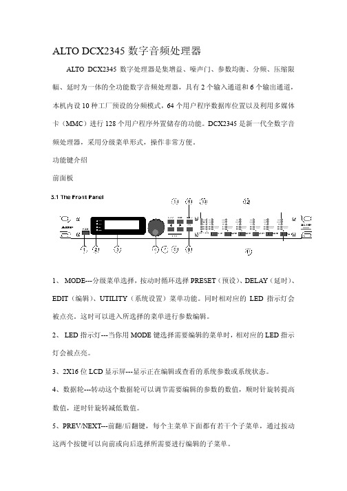
ALTO DCX2345数字音频处理器ALTO DCX2345数字处理器是集增益、噪声门、参数均衡、分频、压缩限幅、延时为一体的全功能数字音频处理器,具有2个输入通道和6个输出通道,本机内设10种工厂预设的分频模式,64个用户程序数据库位置以及利用多媒体卡(MMC)进行128个用户程序外置储存的功能。
DCX2345是新一代全数字音频处理器,采用分级菜单形式,操作非常方便。
功能键介绍前面板1、 MODE---分级菜单选择,按动时循环选择PRESET(预设)、DELAY(延时)、EDIT(编辑)、UTILITY(系统设置)菜单功能。
同时相对应的LED指示灯会被点亮。
这时可以进入所选择的菜单进行参数编辑。
2、 LED指示灯---当你用MODE键选择需要编辑的菜单时,相对应的LED指示灯会被点亮。
3、2X16位LCD显示屏---显示正在编辑或查看的系统参数或系统状态。
4、数据轮---转动这个数据轮可以调节需要编辑的参数的数值,顺时针旋转提高数值,逆时针旋转减低数值。
5、P REV/NEXT---前翻/后翻键,每个主菜单下面都有若干个子菜单,通过按动这两个按键可以向前或向后选择所需要进行编辑的子菜单。
6、N A VIGATION CURSOR KEYS---光标移动键,每个子菜单中都有若干个可以编辑的参数选择,按动这两个键,可以选择需要编辑的参数,选中的参数会闪烁。
7、C ARD---储存卡插入口,在这个插口插入MMC储存卡,利用PRESET(预设)菜单下,可以对该储存卡进行写入、读出等操作。
8、E NTER---确认键,按此键可以对所选择的菜单或编辑的参数数值进行确认。
9、E SC---取消键,按此键可以对所选择的菜单或编辑的参数数值进行取消操作,返回上一级菜单。
10、输入电平指示表,实时指示A/B两个输入通道输入电平的强弱数值。
11、 MUTE---静音按键,按下后将关闭相应输出通道的输出信号,相对应的红色LED指示灯将点亮。
百灵达音频处理器说明书DEQ2496

GEQ 图形均衡器PEQ 参数均衡器DEQ 动态均衡器WIDTH音像宽广调整FBD 回授抑制DYN 动态处理UTILITY 各项设定选单I / O 输入输出功能BYPASS功能不使用开关MEMORY 储存功能METER 表头RTA 音场实时分析模式在使用此手册之前,请了解说明是依官方操作方式进行,不过在一些功能页面皆包括了一些快速按键的使用,操作者在熟悉基本的运作调整后,自然对于快速使用的功能按键会有一番的认识,而在此不再详述。
2. CONTROL ELEMEENTS ( 控制组件)。
2.1 Front panel ( 正面的面版)。
1. LED METER ( 表头指示)。
指示输入的声音讯号电平大小,在其最上方的灯号是CLIP ( 讯号切割) 的指示,表示输入的讯号已经过大,或是在DYN (动态处理)的调整上,其LIMITER( 限制器) 设定限制电平位置过低的原因,参照章节 3.4。
2. METER key ( 表头按键)。
使用这个按键进入后,可以选择三种不同的表头指示模式,参照章节3.10。
3. RTA key ( 音场实时分析模式按键)。
使用这个按键进入后,可以选择三种不同的分析显示,参照章节 3.8。
4. COMPARE ( 功能调整比较按键)。
使用这个按键进入后,可以将你预设的储存资料来与当下所调整的数据来做两种比较。
5. MEMORY key ( 记忆储存按键)。
在这里,你可以将DEQ - 2496 所调整后的数据储存起来,以方便下次的呼叫使用,参照章节 3.9。
图 2 - 1 各项按键显示图 2 - 2 各项按键显示与飞梭旋转控制定义。
6. PAGE key ( 页面选择按键)。
当你是在某项的功能页面时,藉由这个按键再去选择里面的章节出来做调整。
7. functions performed key ( 功能定义执行按键)。
藉由上方的动作后,欲去执行当下的模式或是型态,或改变设定回复预设等,这个功能按键区分 A 键、B 键,是一个去完成的指令键。
Bose ControlSpace SP-24 音频处理器技术参数表说明书

TECHNICAL DATA SHEETProduct OverviewThe Bose ® ControlSpace ® SP-24 sound processor makesoptimizing 2x4 installed and portable sound systems easy.Use the purposefully simple front panel interface for basicoperations, or the intuitive SP-24 Editor software for fullaccess to all signal processing settings.Product Information While many loudspeaker controllers offer complicated user interfaces, the SP-24 processor keeps the front panel interface simple with basic preset/scene recall and gain/delay operations. For full system access, the straightforward and intuitive SP-24 Editor software provides access to all signal processing settings and signal routing, whether connected live or offline. Scenes created with the SP-24Editor software can be saved locally to a PC or, using a USB connection, stored in the SP-24 processor hardware. Full access includes custom channel routing, input and output 9-band equalization, band pass filters, delays, peak limiter,gain and polarity control. Custom loudspeaker EQ curves can be created or Bose professional loudspeaker EQs can be recalled for quick, optimized setup. The hardware includes standard XLR connectors to easily connect to balanced pro-level source devices, amplifiers and powered loudspeakers.ApplicationsDesigned for a wide range of applications, including:•Auditoriums •Houses of worship •Live music performances •Restaurants and bars •Retail stores •Auxiliary zonesKey Features •Real-time control, and the ability to program and store custom scenes with the easy-to-use SP-24 Editor software •SP-24 Editor software provides complete access to all signal processing functions including custom channel routing, inputand output 9-band dual equalization, band pass filters, delays,peak limiter, gain and signal polarity for full system control•Simplified front panel LCD menus and controls arepurposely designed to make it easier to select preprogrammedscenes, gain and delay parameters, or quickly access Bose®loudspeaker presets•USB port enables plug-and-play PC access for systemconfiguration, programming, signal level monitoring andfirmware updates using the SP-24 Editor software•Extensive Bose professional loudspeaker library enablesquick access to factory-created equalization curves while theSP-24 Editor software provides intuitive graphical tools foroptimizing any passive or powered loudspeaker•XLR inputs (2) and outputs (4) for balanced connectivity toprofessional audio gear•Signal and clip LED indicators show the signal status of theinput channels•Front panel lockout feature prevents unauthorized useTechnical SpecificationsTECHNICAL DATA SHEET Audio Performance SpecificationsFrequency Response20 Hz - 20 kHz (+0/-1 dB)THD+N0.015 % (typical)Channel Separation (Crosstalk)100 dB (typical)Dynamic Range107 dB (typical)Integrated DSPAudio Latency 1.52 msA/D and D/A Converters24-bitSample Rate48 kHzMaximum Output Delay170 msAudio InputsInput Channels 2 channelsInputs 2 analog, balanced, differentialMaximum Input Level+18 dBuConnectors, Input XLRInput Impedance Differential 2.2 kΩ @ 1 kHzSensitivity Selectable: 0/+6/+18 dBuAudio OutputsOutputs 4 analog, balanced, differentialConnectors, Output XLROutput Impedance Differential 200 ΩMaximum Output Level+18 dBuIndicators and ControlsAudio Indicators Input signal present (Green LED)Input signal clip at 0 dBFS (Red LED)Electrical SpecificationsMains Voltage100 VAC - 240 VAC (+/- 10%, 50/60 Hz)AC Power Consumption15 WAC Mains Standard IEC (C14)Power Dissapation52 BTU (13.1 kcal)PhysicalRack Space Units1RUDimensions 1.8" H x 19" W x 8.6" D (45 mm x 483 mm x 218 mm)Net Weight 5.9 lb (2.7 kg)Shipping Weight8.6 lb (3.9 kg)Operating Temperature32 °F - 113 °F (0 °C - 45 °C)Storage Temperature-40 °F - 158 °F (-40 °C - 70 °C)Humidity95% relative humidity, maximumGeneralCommunication Port USB Type B (rear panel), PC interfaceTECHNICAL DATA SHEET1.Off/On switch: Turns the product off or on2.Display: 2 x 16 backlit LCD display shows presets, scenes and parameter values3.Navigation controls: 4 pushbuttons allow navigation of the user interface4.SELECT/LOAD control: Pushbutton loads presets and custom scenes. Saves Utility Menu parameters5.SIGNAL/CLIP LEDs: Illuminates to show signal and clipping (0 dBFS) indication for each input channel6.Removable rack ears: For use when installing into rack mount enclosures1.INPUTS A/B: Balanced XLR inputs, +18 dBu max2.OUTPUTS 1 – 4: Balanced XLR outputs, +18 dBu maxB Port: Type B USB port for optional connection to a personal computer running the ControlSpace SP-24 Editor software4.Input power: Power cord inputTECHNICAL DATA SHEETMechanical DiagramsTECHNICAL DATA SHEET All information subject to change without notice.® 2012 Bose Corporation All trademarks are those of their respective owners.Architects’ and Engineers’SpecificationsThe unit shall be a 2-input, 4-output standalone sound processor using a floating point digital signal processing architecture running at a 48 kHz sample rate with 24-bit A/D and D/A converters. Total latency through the unit, analog input to analog output shall total1.52 milliseconds. The processor shall run the following signal processing algorithms: 9-band parametric equalization, routing,band pass crossover, signal delay and peak limiting.Input and output connections shall utilize XLR type connectors.Each input shall be a balanced, differential circuit with an input impedance of2.2 kilohm capable of accepting input signals up to +18 dBu. Each output shall be a balanced, differential circuit with an output impedance of 200 ohms capable of delivering a signal level up to +18 dBu.The frequency response shall be +0/-1 dB from 20 Hz to 20 kHz.The dynamic range shall be 107 dB (typical) from 20 Hz to 20kHz. The THD shall be < 0.015% (typical). Crosstalk shall be <-100 dB (typical).The processor shall include a front panel user interface consisting of a 2x16 blue backlit LCD display, and four navigation buttons.The front panel interface shall allow for the selection of predefined routing configurations and selection of loudspeaker equalization for Bose® professional loudspeakers. The front panel interface shall include the ability to recall custom scenes that are stored in the unit. The front panel interface shall provide access to the following functions: input level, output level, loudspeaker equalization preset and signal delay (per output channel). The processor shall have a maximum signal delay capability of 170 milliseconds per output channel. The front panel interface shall provide a user lockout function and firmware upgrade mode. The processor shall include a Type B USB connector for connection to a personal computer for the purposes of signal processing configuration and firmware updates. The control software shall provide access to signal routing and the following signal processing functions: input level, input equalization, signal routing, output band pass, output loudspeaker equalization,output equalization, output delay, output limiting, and output polarity and level. The control software shall provide the ability to create and store custom configurations within the processor which can be recalled via the software or front panel interface.The control software shall provide input and output metering with 48 dB of signal range.The processor shall have a universal auto switching power supply capable of accepting input voltages from 100 VAC to 240 VAC, 50Hz to 60 Hz. Power consumption shall be < 15 W.The processor shall be constructed of painted steel and weigh 8.6lb (3.9 kg). The processor dimensions shall be 1.8" H x 19.0" W x 8.6" D (45 mm x 483 mm x 218 mm), allowing mounting within a standard equipment rack. The processor shall be a single rack-space unit and have pre-installed 1RU rack ears.The processor shall be the Bose ControlSpace SP-24 sound processor. The control software shall be the ControlSpace SP-24Editor software.Safety and Regulatory Compliance The ControlSpace® SP-24 sound processor complies with CE requirements, and is cUL listed according to UL60065(7th edition) and CAN/CSA C22.2 No. 60065-03, CB approved according to IEC60065 (7th edition) including group and national differences, and is PSE compliant. It also complies with FCC Part 15B Class A (2003), EN55103-1(1997), EN55103-2 (1996), CISPR13 (2003), and Canadian ICES-003 Class A specifications.Product Codes 120V – US 352428-1410240V – AU 352428-2410100V – Japan 352428-3410230V – EU 352428-4410230V – UK 352428-5410。
波士顿CSP-1248商业音频处理器说明书

Product OverviewThe DSP for quick-turn installations — the Bose CSP-1248 commercial sound processor is part of a comprehensive platform that includes loudspeakers, controls, and software that help installers deliver premium sound systems efficiently. An onboard CSP configuration utility and intuitive browser-based UI provide a quick-setup workflow. Common tasks are presented in a logical manner, so you can configure the system faster, reducing installation time while increasing setup accuracy. Once installed, Bose proprietary algorithms offer predictable performance while optional interfaces — such as ControlCenter digital zone controllers and the ControlSpace Remote app — make operation easy for end users.Key FeaturesRight-sized connectivity for cost-effective commercial installation — 8 x 4balanced analog I/O, 4 pair mono-summed RCA inputs, 8 control inputs, 1 control output, mute contact, Ethernet port, and Bose AmpLink connectivity CSP configuration utility with browser-based UI facilitates real-time display and control of levels, routing, thresholds, priorities, scheduled events, Bose loudspeaker EQs, plus input and area EQsRear-panel Ethernet port for PC/Mac configuration; also allows for connection to networks supporting ControlCenter digital zone controllers and the ControlSpace Remote appAutoVolume compensation continuously adapts zone output level based on ambient noise when paired with the Bose AVM-1 sense microphone (sold separately)Opti-voice paging provides a smooth transition between music and announcementsOpti-source level management monitors input level of up to 4 sources, maintaining consistent volume when switching sourcesSmartBass processing expands performance and response at any listening level on supported Bose loudspeakersBose AmpLink output for simplified digital audio connection to compatible power amplifiers, reducing terminations, and related points of failureIntuitive end-user operation — optional ControlCenter CC-1D, CC-2D, and CC-3D (sold separately) digital zone controllers and ControlSpace Remote app provide easy volume control and source selectionApplicationsRetail RestaurantsHospitalityTECHNICAL DATABose CSP-1248commercial sound processorTechnical Specificationsq RCA inputs – Four mono-summed pairs for connection to unbalanced sourcesw Balanced inputs – Eight balancedanalog mic/line inputs with selectable +48V phantom powere PBX input – Dedicated paging con-trol input for 600 Ω telephone systemst MOH output – Standard balancedoutput or source for 600 Ω music-on-hold telephone system. Configured by softwarey AmpLink output connector – 8-chan-nel digital audio output for use with supported Bose amplifiersu Control inputs – Eight digital controlinputs for push-to-talk microphone trig-o Mute – Contact closure connectionthat upon trigger will mute all outputs, NO defaulta Service ports Network – Ethernet connection (RJ-45) for accessing the onboard configura-tion utility, or for connecting ControlCen-ter digital controllers via a PoE network switcho a dqw e r t y uis。
- 1、下载文档前请自行甄别文档内容的完整性,平台不提供额外的编辑、内容补充、找答案等附加服务。
- 2、"仅部分预览"的文档,不可在线预览部分如存在完整性等问题,可反馈申请退款(可完整预览的文档不适用该条件!)。
- 3、如文档侵犯您的权益,请联系客服反馈,我们会尽快为您处理(人工客服工作时间:9:00-18:30)。
重要的安全事项(针对火灾、电击或伤害人体的指示)注意-使用该电器产品时,有以下基本的预防措施:1.使用该产品前请详细阅读全部的安全事项;2.本产品应当接地,如果出现故障时,电流经最小的接地电阻流入大地,以减小电击;本产品的电源线和电源插头都配备安全接地,电源插头应当牢固插入适当的电源座,此电源座应当完全按当地的条例来安装和接地。
警告-接地装置连接不当会导致电击;如果你对产品是否正确接地存在疑问,请委托合格电工或维修人员检查;请不要尝试私自更改产品的电源插头,如果不适合电源插座,可委托合格电工安装适当的电源插座;3.为了减小伤害的风险,当产品在小孩附近使用时,要严密监管;4.请勿在湿度很大的地方使用机器,例如靠近浴缸、洗面盆、厨房水槽、湿度大的地下室或者靠近游泳池和湖泊;5.该产品应当安装与通风良好的地方;6.该产品必须远离热源,例如电暖炉、电热毯或者其他产生热量的产品;7.该产品的电源类型必须符合操作指示或者产品上标明的类型;8.该产品要配备一条两端的电源线(一端的插片长过另一端)。
这是安全装置。
如果你无法把电源插头插入电源插座,请联系电工来更换旧插座。
9.长时间不使用时,请把电源线从电源插座中拔出,从电源插座拔出电源线时,请勿拉扯电源线,应当抓住电源插头将其拔出;10.细心护理,请勿让杂物或者液体从其缝隙掉进机器内;11.当有下列情况时,应委托合格维修人员修理:A.电源线或电源插头已被损坏B.杂物或者液体已掉进机内C.产品已被雨淋D.产品已不能正常操作或在演出中出现明显变化E.产品已跌坏或外观损坏12.当出现在用户维修指南中没有描述的情况时,请勿尝试私自修理,应当委托合格的维修人员修理;13.警告-勿让重物积压或踩踏电源线,切忌拉、拔或强力扭曲电源线。
请勿滥用电源线,不合格的电源线可能导致火灾或对人构成伤害。
目录重要的安全事项(针对火灾、电击或伤害人体的指示) (1)目录 (2)一、设备架构 (3)二、软件操作说明 (3)菜单栏和工具栏 (4)文件 (4)本地设置 (5)设备设置 (6)1)用户管理 (6)2)场景管理 (7)3)网络设置 (8)4)串口设置 (8)5)设备升级 (8)音频输入模块 (9)输入源 (9)均衡器 (10)自动混音器 (11)反馈消除 (12)噪声抑制器 (13)音频输出模块 (14)来源于 (15)音箱管理 (15)限幅器 (16)中控命令生成器操作说明 (17)简易生成中控命令 (17)中控命令生成器操作说明 (17)三、常见问题 (19)一、设备架构设备前面板指示灯:(1)PWR:电源指示灯,接通电源后,灯亮表示设备供电正常,灯灭表示设备供电有异常;(2)STATUS:状态指示灯,灯闪表示系统运行正常,在升级过程中灯会长亮;(3)IN:输入信号指示灯,灯不亮表示该通道无信号输入,灯亮绿表示该输入通道有信号输入,灯亮红表示该输入通道静音;OUT:输出信号指示灯,灯不亮表示该通道无信号输出,灯亮绿表示该输出通道有信号输出,灯亮红表示该输出通道静音;设备后面板接口:(1)AC220V:电源插头,支持AC 100V~240V供电,50~60Hz;(2)M-LAN: 网络接口,连接PC,在线编辑和命令收发控制;(3)RS232:通信接口,连接外部中控设备/支持摄像跟踪;(4)RESET:系统复位按钮;(5)INPUT:模拟音频MIC\LINE输入接口;OUTPUT:模拟音频输出接口;二、软件操作说明软件的安装:软件支持vista、XP、window7、window8操作系统,在安装软件前,请确保电脑已经安装DotNet 。
其次PC端的IP地址中至少有一个地址与设备IP地址(设备出厂默认IP地址为“”)在一个网段内,否则只能查询设备,不能正常连接;如果PC端没有设置与设备相同网段的IP地址,请参考后面的常见问题中第一次使用设备的注意事项正确设置。
(1)菜单栏和工具栏:菜单栏包括软件各项功能菜单,工具栏显示常用功能菜单;(2)复制/粘贴/静音:通道之间的参数复制或相同功能模块之间的参数复制,界面选择框为红色表示该模块可进行复制/粘贴操作;静音是系统静音,按钮按下,全部输出通道静音。
(3)通道参数控制区:显示每个通道的各个功能模块的参数,选择框为红色表示该模块可进行复制/粘贴操作,部分隐藏的模块可直接点中界面左右拖动。
(4)输入/输出通道控制区:显示每个通道的电平和增益,选择其中任意通道,相应的具体参数会在模块3中显示;部分隐藏的通道可使用进行切换;通道选择框为红色时,该通道可进行操作复制/粘贴。
通道选择框为蓝色时,模块(3)中显示为当前通道的参数。
(5)状态栏:显示连接设备当前的登录用户名、IP、DSP的占用率。
菜单栏和工具栏文件1)新建:建立一个新的编辑档案,参数为出厂配置。
2)打开:打开已保存的场景。
3)另存为:把当前配置以文件(.dat)形式保存到本地。
4)中/English:切换界面显示语言。
5)退出:关闭软件。
本地设置1)设备列表:点击“搜索”按钮,查询当前局域网中的在线设备,搜索的结果如上图所示。
“状态”为“!”表示PC端没有设置与设备在同一个网段的IP,无法正常连接该设备,请在PC端添加一个与设备在同一个网段的IP(参考常见问题1),再尝试连接。
如“连接/断开”栏中显示“连接”时,表示设备没有联机,点击“连接”即可连接当前选中的设备,当“连接”变为“断开”时,表示设备联机成功。
如“连接/断开”栏中显示“断开”时,表示设备已经联机,点击“连接”即可从当前连接的设备上断开,当“断开”变为“连接”时,表示设备离线成功。
“连接”和“断开”设备都需要输入用户信息。
2)通道选择:对输入输出通道进行排序、分组、隐藏操作;排序:固定1~N通道;用于查看对应通道的位置。
名称:选中需要排序的通道,按上下移动键调整相应的位置,并且可以修改相应通道的名称。
类别:显示通道属性,不能修改。
显示:选中表示显示,否则隐藏该通道。
分组:显示分组中的通道信息。
3)连接:连接最后一次登录的设备。
4)断开:从当前连接的设备上断开。
设备设置1)用户管理类型用户名密码管理员admin123456用户11能修改个人信息。
修改用户:首先在左边列表中选择需要修改的用户,用户名和密码编辑框显示当前选中用户的信息,输入新信息,点击“修改”按钮即可。
删除用户:选择左边列表中要删除的行,点击“删除”按钮即可删除该用户。
添加用户:在左边列表中选择为空的行,并在右边的用户名和密码编辑框(应该为空)中输入新用户的信息,点击“添加”按钮即可新添加一个用户。
2)场景管理修改场景名:修改选中的场景名称。
保存至设备:将当前的场景保存到选中的设备场景号中。
复位:将选中的场景配置恢复为默认配置。
全部复位:将所有场景配置恢复为默认配置。
加载场景:启用当前选中的场景,通常用于场景更换。
上传至设备:将PC端的场景上传并覆盖选中的设备上的场景。
下载至本地:将当前选中的设备场景保存到PC端。
设置默认启动:将选中的场景勾选为每次开机启用的场景。
取消默认启动:取消勾选的开机启用场景。
在主界面会有直观的当前场景显示及一些常用功能,如下图:下拉框选中显示的场景表示当前正在运行的场景。
保存:将下拉框中选中的场景配置保存到本地。
上传:将保存在本地的场景配置文件覆盖设备上当前下拉框中选中的场景号配置文件,此时的场景并不会自动运行,如需运行,还需“加载”该场景。
加载:将当前下拉框中选中的场景设置为当前运行场景。
3)网络设置用于查看和修改设备的网络地址等信息,在对应的位置输入设备的IP地址、子网掩码、网关,点击确定即可修改当前设备的网络信息。
4)串口设置用于查看和修改当前连接设备的串口信息,设置完成后点击“保存”按钮即可修改当前设备的串口信息;修改后想恢复到默认值,直接点击全部复位按钮即可。
勾上回复结果表示在通过串口发送命令的时候,有回复命令。
5)设备升级设备升级分自动检测升级和手动升级。
自动检测升级:PC连接设备时会检测设备DSP版本,如果版本较低,会弹出提示是否升级,升级点“是”,不升级点“否”。
手动升级:从官方网站上下载升级包,连接设备,在设备设置菜单栏中选择升级,在地址栏中输入升级包所在目录,点击“升级”即可完成对设备的升级。
升级完成后设备会自动重启,但需要重新手动连接。
升级过程中请勿断电,升级还未完成,断电会导致设备死机。
音频输入模块点击该通道可切换上方的功能模块显示框,参考查看通道信息。
输入通道支持分组功能,可将多个通道设置到一个组,调节该组的增益时候,该组下属通道的增益同时变化,设置分组后增益推子上会出现分组标识。
系统提供两类组别:一种是Group组,直接调节增益值;另一种是DCA组,调节增益的百分比。
1)上方编辑框显示通道名称,可修改。
2)Pre/M:pre设置显示的电平是推子前还是推子后;M设置该通道的静音。
3)电平显示和输入增益调节推子。
4)输入增益输入源麦克输入和线路输入可以选择灵敏度,灵敏度高表示传声器的声电转换效率高,对微弱声音信号的反映灵敏;静音:按下表示该通道启用静音,相当于屏蔽该输入信号,弹起表示该通道信号非静音。
测试信号:包括正弦、粉红、白噪声,按下时候可以调节信号发生器的参数,并将信号发生器的信号接入该通道,其它输入信号不再输出;幻象供电:麦克输入是提供幻象供电,用于电容式话筒供电,线输入或非电容式话筒请勿开启,以防烧毁;均衡器均衡器是对频率特性进行补偿和修正,使之达到一个较为平直的频响特性。
3段参数均衡全部直通:将所有频段信号全部旁通,信号直接进入下一个处理模块;按下表示直通有效,即均衡器不启作用,所有频段信号全部直通到下一个处理器,弹起表示均衡器启作用,信号经过均衡器处理后再输出。
段直通:当进行EQ调整后,可以针对某些已设定的频段进行旁通取消的动作,只对该段作用。
中心频率:需要做均衡处理的频率。
增益:频率中心点的增益/衰减值。
当这个值为0时,中心频率,Q值均无效。
带宽:频率点的带宽,即该段在中心频率周围的影响范围,数值越大带宽越大,影响范围越大。
全部复位:将所有参数回复到出厂设置。
自动混音器在会议室中,有8 只话筒,如果这时候8 只话筒都打开并具有相同的电平,而只有一个人在发言因为其余7 只话筒会拾取房间中的噪声、混响等,影响音质。
其次由于这些话筒的存在,声反馈前所能达到的最大增益中有效声的成分相对下降,音量出现不足。
自动混音器实时调整每个输入通道增益来适应总电平,通过提高高电平信号的增益,减少低电平的信号的增益保持整体系统增益不变。
在增益分配型自动混音器中,通道不是恰好是打开或关闭,而是位于它们之间的任意状态。
相对来说,音量越高的通道,其增益也越高。
如果几个通道音量相同,则增益也相等。
