射频监测仪说明书
射频场强仪简易操作说明书

射频场强仪简易操作说明书一.功能按键介绍:1.[Run/GHz] 运行键(开始扫描)或停止键(停止扫描,此时处于监听状态),同时在输入频率的时候做GHz 的单位用。
2.[Mode/MHz] 调制模式键一共有4 种模式:W-FM(宽频调频),(窄频调频幅),SSB(单边模式),AM(调幅),同时在输入频率的时候做MHz 的单位用。
3.[Sweep/KHz]扫描模式键三种模式:(F)自由模式,(1)单次模式,(S)静躁模式4.[Marker/DEL] 标记键M 出现时,上下键可移动光标察看光标位置处的各项参数;三角出现时,对两个光标位置进行差值比较;S 出现时,可以通过上下按键或旋纽来移动调整右侧静噪的数值。
在输入的时候可以删除当前你输入的字符。
5.[Menu] 菜单键可以用来设定各项参数。
二.基本操作:1.将天线安装上。
2.开关机:按[POWER]键开关机3.LCD 屏幕的调节:[SHIFT]+[7](即先按SHIFT 键,然后再按7 键)打开或关闭背光灯[SHIFT]+[8]打开屏幕亮度调节界面,上下按键或旋纽来选择亮度按[ENTER]键确定。
4.测量频率的选择:开机自检后默认的中间频率是2000MHz,你可以直接输入数值和单位来确定你需要测量的频率。
你输入的频率为中间频率,它的跨度根据你选择的接受模式而不同,20M为或2M。
你也可以按[SHIFT]+[1]然后输入你需测量的初始频率和终止频率来选择你测量的范围。
按[ENTER]键确定。
5.[SHIFT]+[2]可以设定SPAN(跨度)值,有的接受模式SPAN(跨度)值是默认的,不是可以任意调整的。
6.[SHIFT]+[3]可以设定LCD 显示的LEVEL(电平)的起始数值和分辨率,数值通过[上/下]按键选定。
按[ENTER]键确定。
7.能量的测量:[SHIFT]+[4]然后输入你要测量的频率值可以测量你选定的频率的能量(电平数值)。
[SHIFT]+[5]用数字键在1-9 之间选择一个,然后输入你要测量的频率值可以同时显示多个你选定的频率的能量。
RPM3000射频功率计使用说明书

RPM-300M射频功率&数据测试仪(RF Power Meter &Datacom Tester)使用手册(注:英文版摘录翻译)通告版权所有© 2008 BELLNET CO.,LTD 保留所有权利。
感谢您选用BELLNET (贝尔网迅) RPM-300M射频功率&数据测试仪,在使用前,请仔细阅读本说明书,以便正确操作。
根据美国及国际版权法,未经BELLNET公司事先同意和书面许可,本手册的任何部分不得以任何方式或手段(包括电子存储、检索或翻译为另一种语言)进行复制。
安全须知在本仪器工作的各个阶段,都必须采取以下一般性安全措施。
不采取这些安全措施或不遵从本手册其他地方所述的特定警告,将会违反仪器设计、制造和使用的安全标准。
BELLNET对于客户违反这些要求所造成的后果不承担任何责任。
总则如不按照操作手册使用本产品,其保护功能可能会失效电池警告:仅可以使用锂电电池,采用交流适配器来为锂电电池充电,有关其他安全方面的详细信息,请参考阅本手册安全信息部分注意:可能涉及产品性能,不按照规范操作可能会影响产品性能,请不要拆机器,则否会造成零部件损坏,只有有资格的人员才能进行维护。
目录一、仪表通用说明 (4)1,正视图 (4)2,信号指示灯 (5)3,按键 (6)4,物理连接口 (7)5,打印、供电端口 (7)二、E1测试功能操作模式 (8)三、以太网的测试功能操作模式 (11)四、射频功率计测试操作 (17)1,RPM-300M主机显示版本 (17)2,PC电脑显示软件版本 (20)五、测试结果菜单管理操作 (24)六、保修期 (26)一、仪表通用说明欢迎使用BELLNET RPM-300M 射频功率※数据测试仪。
您可以使用这一紧凑、轻巧而性能多样的测试仪来执行多种基于E1、10/100M 、射频功率接口的测试。
快速验收电路、检查质量、观察信号信息、及射频功率的测试――都能通过一个简单的基于键盘的用户接口和一个简洁的LCD 显示屏幕来完成。
射频仪操作

一:打开电源键→仪器自我检测(等音乐声结束)→按启动键→开始自动测阻抗→按刺激键(电刺激“幅度”栏灯亮)→把确定键向“+”方向转一下调制m A灯亮→按确定键2下(电刺激栏灯闪)→旋转确定键调至1.5mA→按确定键一下→确定键向右转至“频率”栏灯亮→按确定键→调至10HZ→按确定键→转两下,菜单栏箭头调至4→按确定键→按启动键(开始电刺激)→结束后按停止→按热凝键(热凝灯亮)→按确定键2下→调温度(根据医生口头医嘱执行)→按确定键→把菜单栏箭头调至3→按确定键→按启动键
二:治疗过程中根据口头医嘱需要升温时,按停止键→按确定键2下→升温→按确定键→把菜单栏箭头调至3→按确定键→按启动键。
射频监测仪说明书
射频监测仪装置原理:发电机内部的放电现象在定子绕组中产生很多的高频分量,电弧发电辐射的电磁波频谱很广,其中一部分将传入定子绕组的中性点接地线中,由于发电机中性点对地电位很低,发电机任何部位的电弧放电都将在中性点接地线内产生相应的射频电流,射频监测仪是通过高频电流传感器来监测发电机中性点的电弧的高频信号,以发现定子线圈内部放电现象。
由于发电机定子线圈中存在多种射频干扰信号,其发放电流信号通过中性点接地线流向接地点,高频电流互感器把此射频信号耦合到监测仪,该射频检测仪可以监测到放电电流的强弱,以此来探测发电机局部放电的程度,实现对发电机定子绝缘的状态检测及故障报警。
运行监视1.装置构成①监测仪、遥控板、高频电流传感器、熔丝及涌浪电容注:监测仪和遥控板的操作面板功能基本相同,监测仪显示是指针显示,还有两个多圈电位器(设置报警值,因为带锁,调整前先松锁,完毕后锁紧)而遥控板是液晶表屏显示,无法设置报警值。
②本装置监测仪引自杂用MMC A段02D柜遥控板电源引自集控楼PC&MCC A 段07A 柜(杂用MCC A段02E柜为其备用电源)③熔丝及涌浪电容的功用高频电流传感器接在发电机中性接地变压器前面,由于高阻变压器对射频信号衰减很大,使监测仪的读数无法读出,因此设置一个涌浪电容器(0.01uf,DC 100KV),并联在接地变上,同时为了不因电容漏电引起误电流,在电容器支路上串接一限流容丝(0.5-1A / 10-27V)。
2.指示灯注:上述四个指示灯并带按键功能,即可分别进行电源开关,自校检测,报警复位操作3.装置自检周期为60S,按下遥控板或监测仪上自校按扭,仪器进入自校周期。
在前半个周期读出输出值应小于30uv,后半个周期输出接近满刻度10Kuv,10S后开始进入报警状态。
在自校周期结束后,按下各报警验证按钮,仪器进入监测状态。
4.遥控板与监测仪接通通过监测仪电源供应部件板上开关S1控制,S1拨到“OFF/REMOTE”接通,而S1拨到“ON/SELF”不接通5.报警处理验证报警并观察指示记录,以确定报警信号继续存在,关注发电机运行参数以及其他监测仪的情况,进行综合分析,并与厂家联系。
射频仪正确操作方法

射频仪正确操作方法
射频仪是一种常用的测量和调节射频信号的仪器。
以下是射频仪的正确操作方法:
1. 接通电源:确保射频仪的电源线已经正确连接并接通电源。
2. 预热时间:在使用射频仪之前,通常需要给仪器一定的时间进行预热。
具体的预热时间一般会有说明书中指定。
3. 连接天线或信号源:将天线或信号源连接到射频仪的输入端口。
确保连接的稳定和正确。
4. 设置测量范围:根据需要,设置射频仪的测量范围。
可以通过旋钮、按键或触摸屏来调整测量范围。
5. 调节射频信号:通过调节信号源或其他调节装置,产生或调整射频信号的频率、功率等参数。
6. 测量结果:观察射频仪显示屏上的测量结果。
通常可以得到射频信号的频率、功率、带宽等数据。
7. 注意测量误差:射频仪的测量结果可能会有一定的误差。
在进行准确测量时,需要注意和排除可能的干扰因素,如电磁干扰、信号衰减等。
8. 关闭射频仪:使用完毕后,先关闭射频信号源,再关闭射频仪的电源。
以上是射频仪的正确操作方法,但具体操作步骤可能会因不同的射频仪型号而有所差异。
在使用射频仪之前,建议先仔细阅读相关指南和说明书,熟悉具体的操作要求和注意事项。
减肥仪器微波射频仪使用说明书

微波射频仪北京鸿缘润医学科技有限公司尊敬的用户:为了您更好了解和正确使用微波射频仪,请您仔细阅读本说明,并注意保存。
目录一、【操作步骤】二、【操作说明】三、【操作建议】四、【操作流程】五、【操作手法】六、【注意事项及禁忌症】七、【技术优势】八、【疗程后的维护建议】产品介绍Products Introduction微波射频仪-采用了一个电容耦合电极来传送无线电波能量,提高真皮层及皮下组织3-5毫米的温度,促进细胞的代谢,增强血液循环,并增强胶原组织的伸展。
在2450Mhz的高频率下,这个电场每秒钟变换极性24.5亿次。
为了回复电极的快速变换,皮肤内的电荷离子在同样的频率下会变换方向。
高频电波进入皮下组织使皮下组织的自然电阻运动产生热能,当温度达到摄氏45度至65度零介点,胶原质产生立即性收缩的同时,刺激真皮层分泌更多的新的胶原质来填补收缩和流失的胶原质的空缺,从而再次托起皮肤的支架,恢复皮肤弹性。
当射频能量作用于眼袋部位,利用射频电波能量直接穿透表皮到达皮下1.2-3.6mm处,以每秒钟24.5亿次的震荡使细胞加速运动.这种“内生热”效应会加大细胞间的引力作用,紧缩肌肉和细胞.加速脂肪细胞的运动将细胞内的脂肪液化分解,将多余的水份及毒素通过淋巴管排出体外,恢复肌肉和细胞的紧张度,从而收缩拖垂的脂肪达到彻底消除眼袋及眼睑浮肿和鱼尾纹.射频电波直达皮肤深层脂肪层,更新排列脂肪结构,并且深度的溶解顽固脂肪,缩小脂肪团的体积,脂肪团内溶物----(甘油三酯)吸收射频热能后迅速分解为游离脂肪酸,异化为二氧化碳和水。
溶解的脂肪经淋巴、肠道被排出体外,从而达到明显的瘦身效果。
技术参数仪器配件组成:电源线、地线、探头、说明书微波射频美容系统微波射频美容作为美容行业的第三代科研成果:是一种革命性的先进“祛眼袋、祛皱、嫩肤、塑形”的技术,无须开刀和填充,利用真皮层及皮下组织加热的原理,使自身的胶原蛋白分裂和繁殖,有效的支撑起皮肤、填平皱纹,祛铅,祛汞。
8717系列电磁射频测量仪说明书

P/N 43004100 Rev.A1981FirmwareThe Series 8717-117XX and the Model 8718B use identical firmware (internal software) and identical User’s Software. There is only one minor difference in the operation that involves the default setting for the LCD backlight:The default setting for the LCD backlight is ON for theline operated Series 8717-117XX and it is OFF for thehand-held Model 8718B.The firmware in both meters can be used to turn the backlight on and off.Controls and IndicatorsPower Control:It is suggested that the keypad be used to turn the Series 8717 on and off under normal conditions. Shut the meter off using the keypad prior to moving the ACON/OFF on the rear of the meter to the OFF position.The LINE POWER indicator on the front panel is designed to moni-tor the status of the AC power Switch.Alarm:The nine-pin alarm connector on the rear panel pro-vides a simple way for remote indication that the user-controlled alarm threshold has been exceeded. Both a TTL signal and a set of SPDT relay contacts are provided to indicate alarm sta-tus. The meter firmware is used to turn the alarm on and off and to set the alarm threshold. The alarm threshold is set in proportion to the full-scale value of the probe that is being used. For example, if a shaped probe with a full scale indication of “300% of Standard” is used and the alarm threshold is set to 10%, then the audio alarm on the front panel will be activated whenever the probe is subjected to a field in excess of 30% of Standard. The TTL signal and the relay contacts operate in par-allel to the front panel audio signal. The TTL signal goes High under alarm conditions.Interface Switch:The interface switch activates one of the two remote interfaces – the GPIB or the RS232serial port. Although the GPIB interface is most likely to be used for day-to-day oper-ation, the RS232 interface is required to run Narda ’s User ’s Software, which is designed to operate via the RS232 port only.Therefore, you must select RS232 in order to load probe cali-bration information or to extract logged data. It is convenient to have probe calibration information stored in the meter when making single-frequency measurements. Under those condi-tions, probe correction factors can be used to reduce theamount of measurement uncertainty. Refer to the 8718B User’s Guide for further information.Other:For all other operations refer to the 8718B User ’s Guide.USA: 435 Moreland RoadHauppauge, NY 11788Tel 1-631 231-1700 Fax 1-631 231-1711E-Mail *******************www GERMANY: Sandwiesenstr 7D-72793 PfullingenTel +49-7121-9732-777 Fax +49-7121-9732-790E-Mail ********************www.narda-sts.de ❖❖❖CAUTION ❖❖❖Do not place your eye tightly against the front panel of the meter in the area of the Probe Test window while the Test Source indicator is illuminated.Probe Test:The output of the high frequency test source is very low power. The field generated is far below the Maximum Permissible Exposure (MPE) levels in the IEEE C95.1-1999standard at a distance of only one-inch from the front panel. The Test Sources automatically turn off 20 seconds after the Test Source key is pressed. The Test Source indicator is illuminated whenever the test sources are active.。
分体射频使用说明书-10页文档资料
◆响应时间:<0.5S
四.安装说明
请用户按照本说明书中的安装规范进行安装:根据现场的不同情况可分为整体安装和分体安装。一般采用在罐顶垂直安装的方式,在测量非导电物料时,也可采用侧壁横装或斜装。当采用侧装时,最好使仪表向下倾斜15度安装。根据安装方式不同,又可分为安装管座安装和法兰安装。
◆稳定性:0.1pF/6个月(最大漂移)
◆火花防护:内置火花防护电路
◆传感元件安装:NPT螺纹或法兰安装(规格可选)
◆插入长度:标准450mm(插入长度IL)-250mm(屏蔽CSL长度)
也可依用户要求提供,最大6m最小0.1m
◆电气接口:M20*1.5
◆分体电缆:标准长度为5米,最长20米(仅对分体)
要练说,先练胆。说话胆小是幼儿语言发展的障碍。不少幼儿当众说话时显得胆怯:有的结巴重复,面红耳赤;有的声音极低,自讲自听;有的低头不语,扯衣服,扭身子。总之,说话时外部表现不自然。我抓住练胆这个关键,面向全体,偏向差生。一是和幼儿建立和谐的语言交流关系。每当和幼儿讲话时,我总是笑脸相迎,声音亲切,动作亲昵,消除幼儿畏惧心理,让他能主动的、无拘无束地和我交谈。二是注重培养幼儿敢于当众说话的习惯。或在课堂教学中,改变过去老师讲学生听的传统的教学模式,取消了先举手后发言的约束,多采取自由讨论和谈话的形式,给每个幼儿较多的当众说话的机会,培养幼儿爱说话敢说话的兴趣,对一些说话有困难的幼儿,我总是认真地耐心地听,热情地帮助和鼓励他把话说完、说好,增强其说话的勇气和把话说好的信心。三是要提明确的说话要求,在说话训练中不断提高,我要求每个幼儿在说话时要仪态大方,口齿清楚,声音响亮,学会用眼神。对说得好的幼儿,即使是某一方面,我都抓住教育,提出表扬,并要其他幼儿模仿。长期坚持,不断训练,幼儿说话胆量也在不断提高。目录
射频仪的使用方法

射频仪的使用方法
射频仪是一种专业的测试仪器,通常用来测量和检测各种电参数,如频率,电平,相位,阻抗,电源,噪声等。
射频仪用于各种系统的调试和维护,是工程师的必备测试工具。
由于射频仪的功能多样,测量结果更加精确,因此被广泛应用于无线电,电信,测控,航空,军事,电视等领域。
射频仪的主要功能包括:测量频率,测量电平,测量相位,测量阻抗,测量电源,测量噪声,测量功率。
首先,在使用射频仪之前,应当校准仪器。
校准就是使射频仪的测量结果与真实值一致。
校准可以通过调整被测物体的输入参数来完成。
其次,用户应当充分了解仪器的功能,并按照正确的操作步骤,确定测量参数和范围。
将射频仪连接到被测物体,开启射频仪,调节仪器的测量参数,然后根据记录的测量结果,对电参数进行判断和调整。
此外,用户应当注意射频仪的使用环境,要求使用环境清洁、通风良好,湿度在50%以下,静电场的变化不要太大,并且要避免强磁场的干扰。
同时,定期检查仪器,保证仪器正常工作,并定期更换耗材,防止仪器因磨损而损坏。
最后,在使用射频仪时,用户应当遵守一定的安全操作步骤,以保障人身安全和设备的安全稳定。
射频仪产生的电磁波有时会对人的健康产生不良影响,因此用户在使用射频仪时,应当注意保护自身。
以上就是射频仪的使用方法,用户在使用仪器时,要注意仪器的校准,充分了解仪器功能,操作步骤,调整测量参数,注意安全,保证仪器的准确性和精确度。
这样,射频仪才能发挥最大效果,为用户提供最可靠的测量数据。
射频导纳说明书

射频仪操作说明

R-2000 B射频热凝器使用操作说明1、连接三项插头电源,连接好各种导线,确保负极板与病人皮肤充分接触,负极板粘帖的位置应避免热凝器的电流环路通过病人的心脏。
负极板粘贴位置:小腿肚部、小腹部、臀部等肌肉比较丰厚的部位。
粘贴注意事项:从柄端慢慢揭去极板隔离纸,将可见金属箔的一面(极板正面)紧贴于病员清洁、干燥、无毛、多肉、无骨髂突出且靠近手术部位处,用引线夹夹住手柄,注意夹内两金属片应与极板柄上金属箔接触,且使金属箔不外露。
2、将手术电极与电极配电缆连接好,然后打开电源开关,准备热凝治疗。
3、按“启动”键测阻抗,若有两个以上靶点时,则直接按阻抗键即得其阻抗值。
(注:血液、脑脊液的阻抗在50Ω左右,椎间盘的阻抗在150Ω-300Ω之间,纤维环的阻抗在200Ω左右,肌肉的阻抗在300Ω-400Ω左右,骨骼的阻抗大于500Ω).4、按“刺激”键,准备刺激。
按“确定”键至电压数值闪动,调节数值为1.50(逆时针旋转确定键数值变小,顺时针旋转,数值变大),然后按“确定”键。
顺时针旋转“确定”键一下,按“确定”键至频率数值闪动调节数值为10,然后按“确定”键,顺时针旋转“确定”键至最后一项,按“确定”键返回刺激界面。
按“启动”键开始刺激。
必要时调节为2.0进行刺激。
此为电压刺激。
若需电流刺激则选择第二项,进行参数设置,数值与电压刺激与电压刺激数值相同。
5、按“热凝”键,准备热凝治疗。
按“确定”键至温度数值闪动,调节数值至所需温度,然后按“确定”键,顺时针旋转“确定”键至最后一项,按“确定”返回热凝界面。
按“启动”键开始热凝。
若需改变温度方法同上。
60°为试验量,病人一般没有什么感觉,70°时病人会出现原有疼痛部位发热、发酸、发胀的感觉,80°~95°为治疗温度,治疗周期依病情而定。
若需更换电极进行热凝治疗,则需要重新启动机器。
6、热凝治疗完毕后,将手术电极与电极适配电缆断开后,关闭电源开关。
射频仪器的操作方法

射频仪器的操作方法
射频仪器具体操作方法取决于不同仪器的型号和功能,一般操作步骤如下:
1.先按照仪器说明书的要求安装好设备,并连接好所有的连接线。
2.开启电源,仪器处于待机状态,然后进行基础设置。
这项设置包括选择仪器需要测量的射频频率范围,增益和谐波消除等。
3.为了准确测量信号,确保各个仪表的校准状态。
对仪器进行校准,通常需要使用专业的校准工具和标准样品来进行。
4.对待测样品和测试电极,进行合适的放置配置设置。
确保样品安装正确,以允许仪器测量出关键参数。
5.启动测量。
仪器根据您所选择的设置参数进行处理,并输出结果到屏幕或者存储介质。
6.对测量结果进行分析。
可以使用计算机连接到仪器,使用专业的软件对测量结果进行分析与处理。
7.经过数次检验和对比分析量测结果,确保数据的准确性。
确认测量数据。
8.结束测试并清理仪器。
将仪器归位并注意仪器的使用与保养。
初普射频仪眼部操作方法

初普射频仪眼部操作方法
首先,确保仪器已经准备就绪并且安全接地。
接着,按照以下步骤操作:
1. 打开仪器的电源开关,并等待仪器启动完成。
2. 调节仪器的频率和功率,根据需要选择合适的参数进行设置。
3. 在操作之前,使用消毒液或消毒棉球清洁测量头部位。
4. 让被测者坐在舒适的位置上,双眼睁开并注视前方。
5. 将测量头按照说明书的方法正确放置在眼部位置上,并确保与眼部接触良好。
6. 在屏幕上观察信号波形,并调节位置和角度,以获得清晰和稳定的波形信号。
7. 开始进行眼部测量,注意被测者的眼睛状态并适时调整参数。
8. 测量完成后,关闭仪器的电源开关,并进行仪器的清洁和消毒工作。
以上就是初普射频仪眼部操作方法的简要步骤,具体操作时请务必仔细阅读说明书并按照要求操作。
射频仪的使用方法

射频仪的使用方法射频仪(RadioFrequencyInstrument)是一种用于收发射频讯号的仪器,它可以把电子设备发出的射频讯号传送到另一个电子设备中接收和改变。
射频仪出现于20世纪50年代,被广泛应用于频率测量、电子义务、接收信号术控制等多种领域。
它的使用方法同时也是一门技术学科,它的技术性有助于人们精确掌握收发射频、进行相关操作,以实现更精确、更有效的工作。
一、射频仪基本原理射频仪的基本原理是,它能够将一个电子设备发出的射频讯号发送到另一个电子设备中接收和改变,这种讯号叫做射频信号(Radio Frequency Signal),是一种带有某种频率的信号。
当射频信号被发送到另一个电子设备中时,就会发生一系列的改变,这些改变会改变射频信号的频率、幅度和形状等。
射频仪就是要控制这些变化,使这种射频信号达到其有效使用的目的。
二、射频仪的用途1.量频率:射频仪能够测量频率,其原理是射频仪通过检测电子设备间信号传输所产生的变化,从而得出信号的频率,以便对信号作出准确的分析和比对。
2.子义务:射频仪可以在电子义务中被用作测试情况的工具,其优势在于可以测量宽频率曲线,可以调节信号的大小,以及能够检测电子设备间的不同信号。
3.制信号技术:射频仪可以控制信号的传递,尤其是在高频段,能够大大提高信号的准确性和可靠性。
三、射频仪操作注意事项1.作之前要熟悉射频仪的控制表,确定控制仪表上的数值,根据实际情况调整操作细节。
2.作时要紧贴射频仪的说明书,根据规定的要求完成调整操作。
3.作时要严格控制无线电能量,以免造成不可控制的后果,并应定期对操作设备进行检查和维护,以确保设备的可靠性和稳定性。
四、射频仪的应用1.频仪被用于测量频率、分析信号、控制信号技术、监控通讯设备等,在这些领域都发挥着重要作用。
2.频仪还被广泛应用于电视节目频道检测、广播电台调频监督、全频段调幅信号控制。
3.频仪也用于高效的超宽带网络中,它可以提高网络的传输效率,以实现更好的多无线技术。
发电机监测射频仪说明书
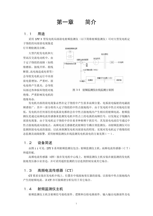
第一章简介1.1用途采用SJY-3型发电机局部放电射频监测仪(以下简称射频监测仪)可对大型发电机定子绕组的局部放电现象进行早期检测及诊断。
大型汽轮发电机和大型高压交流电动机中,由于定子绕组的故障(如绝缘磨损、接线开焊、股线断裂、高电场造成电晕等)会导致发电机运行中内部放电量增加,严重时,放电处将产生弧光,会导致局部过热和损坏绕组对地绝缘,严重影响发电机的绝缘寿命。
发电机内部的放电现象必然在定子绕组中产生很多高频分量,电弧放电辐射的电磁波频谱很广,其中一部分将传入定子绕组的中性点接地线中。
由于发电机中性点对地电位很低,发电机内任何部位的电弧放电都将会在中性点接地线内产生相应的射频电流,射频监测仪是通过高频电流传感器来监测发电机中性点上的电弧的高频信号,以发现定子线圈内部放电现象。
由于发电机定子绕组中存在着多种射频干扰信号,其发放电电流信号通过中性点接地线流向接地点,高频电流互感器把此射频信号耦合到监测仪,该射频监测仪可以监测到放电电流的强弱,以此来探测发电机局部放电的程度,实现对发电机定子绝缘的状态监测及故障报警。
采用射频监测仪在线监测发电机放电的方案见图1-1。
1.2设备简述由图1-1可见,SJY-3系列射频监测仪包含:射频监测仪主机、高频电流传感器(CT)和遥控板。
高频电流传感器(CT)接在发电机中心线上,射频监测仪主机安装在被监测的发电机接地变压器小室旁边,并可采用遥控监测的方法连到控制室或其它场合。
1.3高频电流传感器(CT)CT要求安装在发电机中线上,位置在中线接地变压器的前端,以拾取中性点接地线内产生的射频电流。
该CT亦可接频谱分析仪用于其它场合。
1.4射频监测仪主机射频监测仪主机含射频信号接收部件、逻辑和自检电路部件、输入输出电路部件及电源供应部件。
主机面板上安置指针式仪表以指示发电机系统的射频电平,图案1-2所示。
该面板上外设有控制、显示合用的带指示灯的四个按键,两个用以设定报警电平的电位器。
一体化手持式射频测试平台专属说明书
一体化手持式射频测试平台
多功能可扩展平台,无需多台仪器
根据安装的型号和选项,FSH 手持平台可一机多用:
►频谱分析仪►干扰查找分析仪►电缆天馈线线分析仪►双端口矢量网络分析仪►微波和射频功率计►EMF场强测量
►EMC预认证测量接收机►
各种移动通信信号解调分析
R&S®FSH
系列手持式频谱分析仪:
►锂离子电池组►USB 接口线►LAN 网线
►AC 电源适配器►用户手册
►
3年保修 (电池和附件为1年
)
标准配置
关键特性:
f 一体化仪器满足现场测量需求f 干扰分析和地理标记f 电磁场测量f 轻松操作
f 免费的远程控制软件和应用
支持多种无线通信标准:满足GSM/GPRS/EDGE 、WCDMA 、TD-SCDMA 、 CDMA2000®、1xEV-DO 、LTE TDD 、LTE FDD
调制测量
矢量网络分析仪模式:用于电缆损耗和天线测试与表征、故障点测量。
用于传输参数测量的双端口矢网性能
通过LAN或USB接口进行远程控制:R&S ® FSH可通过USB或LAN接口进行远程控制,并集成到用户特定的程序中
向导支持常见测量功能:用户可自定义的测试序列,可减少现场操作
错误。
射频识别设备使用说明书

射频识别设备使用说明书使用说明:1. 前言射频识别(RFID)设备是一种用于识别和追踪物体的技术。
本使用说明书将向您介绍如何正确操作和维护射频识别设备,以确保其正常工作并取得最佳效果。
2. 设备概述射频识别设备由以下主要部件组成:- RFID读写器:用于读取标签上的数据和写入数据到标签中。
- RFID标签:携带着物体的唯一身份信息,可与读写器进行通信。
- 电源适配器:用于为设备供电。
- 连接线:连接读写器、电源适配器和其他外设。
3. 设备安装在使用射频识别设备之前,请确保完成以下步骤:- 将电源适配器插入电源插座,并将其连接到设备上。
- 将读写器连接到电源适配器或电脑上。
- 确保与计算机或其他设备的连接线正常连接。
4. 设备操作本节将向您介绍射频识别设备的基本操作步骤:- 将带有标签的物体放置在读写器附近。
- 启动读写器,可以在屏幕上或按键上找到相应的开启按钮。
- 读写器会自动识别标签,并将标签上的数据显示在屏幕上。
- 根据需要,您可以选择将新数据写入标签中,使用读写器上相应的按钮执行写入操作。
5. 设备维护为确保射频识别设备的长期稳定运行,请注意以下几点:- 定期清洁设备表面和连接线,并保持干燥。
- 不要拉扯连接线,以免损坏传输数据的线缆。
- 避免将设备长时间暴露在高温或潮湿环境中。
- 定期检查设备和连接线是否有损坏,如有损坏请及时更换。
总结:本文为您提供了一份简要的射频识别设备使用说明书,旨在帮助您了解设备的基本操作和维护方法。
请按照本说明书中的步骤正确操作设备,并注意设备的保养和维护,以确保其正常工作和使用寿命。
如果在使用过程中遇到任何问题,请及时查阅本说明书或咨询专业人士。
祝您使用愉快!。
射频仪使用指南

射频仪使用指南射频仪是一种用于测量和分析射频信号的仪器。
它广泛应用于通信、电子、无线电、卫星等领域,以帮助工程师进行信号测试、频谱分析和干扰排查。
本文将介绍射频仪的基本使用方法和注意事项,以帮助用户正确、高效地使用射频仪。
一、仪器介绍射频仪通常由主机、天线、显示屏和操作按键组成。
主机是射频仪的核心部分,负责接收和处理射频信号。
天线用于接收射频信号,并将其传输给主机。
显示屏用于显示测量结果和参数。
操作按键则提供了对仪器的控制和设置功能。
二、基本操作1. 接通电源:将射频仪的电源线插入交流电源插座,并将仪器的电源开关打开。
2. 设置参数:通过仪器的菜单或按键设置界面,设置所需的测量范围、测量单位、触发方式等参数。
3. 连接天线:将天线连接至射频仪的天线接口,并确保连接牢固。
4. 接收信号:将天线对准待测信号源,并观察仪器显示屏上的射频信号波形或参数。
5. 数据分析:根据需求,对接收到的射频信号进行参数分析、频谱扫描等操作。
6. 结果展示:通过显示屏上的图表、曲线或数字结果,可以直观地了解射频信号的特性和性能。
三、注意事项1. 安全使用:射频仪在工作时会接收到大量的射频能量,使用时需注意避免直接暴露在高强度射频辐射下,以免对人身安全产生影响。
2. 适当保护:射频仪是精密的测试仪器,使用时要防止碰撞、摔落和水激等外力损坏。
3. 正确存放:在不使用射频仪时,应将其存放在干燥、防尘的环境中,并避免长时间暴露在高温、高湿度环境中。
4. 定期校准:射频仪的测量精度会随时间的推移而变化,建议定期进行校准,以确保测量结果准确可靠。
5. 仪器保养:定期清洁仪器表面和天线接口,避免灰尘和污染物对测量结果的干扰。
射频仪的正确使用对于各个领域的工程师来说都非常重要。
通过本指南的介绍,相信用户能够更加熟练地操作射频仪,并正确分析射频信号的特性与性能。
希望本文对您有所帮助,祝您在射频测量和分析工作中取得优异的成果!。
RF Explorer MS2711B D 手持射频分析仪说明书
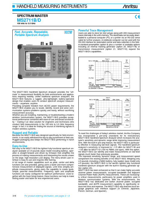
The MS2711B/D Handheld Spectrum Analyzer provides the “ulti-mate” in measurement flexibility for field environments and applica-tions requiring mobility. Unlike traditional spectrum analyzers, the MS2711B/D features a rugged, ultra-lightweight, battery-operated design that enables users to conduct spectrum analysis measure-ments – anywhere, anytime.Providing complete freedom from AC/DC power requirements, the MS2711B/D enables you to locate, identify, record and solve com-munication systems problems quickly and easily, without sacrificing measurement accuracy.Whether you are installing, maintaining, or troubleshooting a modern wireless communication system, the MS2711B/D provides excep-tional performance combined with ease-of-use and broad functional-ity – making it an ideal solution for engineers and technicians who conduct field measurements in the 100 kHz to 3.0 GHz frequency range. In fact, it is ideal for finding the source of interfering signals in modern wireless systems.Rugged and ReliableBecause the MS2711B/D was designed specifically for field environ-ments, it can easily withstand the day-to-day punishment of field use. Rugged packaging also keeps the MS2711B/D performing in harsh environments.Easy-to-UseNot only is the MS2711B/D the lightest fully-functional spectrum an-alyzer available at 4.5 pounds (base model including battery), oper-ation is straight-forward and driven by firmware that simplifies the process of making measurements and interpreting the results shown on the large, high-resolution LCD display. The menu-driven user in-terface is easy to use and requires little training.A full range of marker capabilities such as peak, center and delta functions are also provided, giving users a faster and more compre-hensive measurement of displayed signals. Limit lines simplify am-plitude measurements, giving users the capability to create quick, simple, pass/fail measurements. Frequency, span and amplitude functions are easily configured for optimum performance. Used to-gether with the Save Setup feature, these functions can help to make testing easier and faster for less experienced users.Powerful Trace ManagementUsers are able to store ten test setups along with 200 measurement traces internally in the unit’s memory. The stored data can be easily down-loaded to a personal computer (PC) or a printer via an RS-232 serial cable for further analysis. A notebook computer can be used with the RS-232 interface for automated control and data collection in the field.A standard preamplifier (option 8) plus a number of available options including an internal tracking generator (option 20, MS2711B) or transmission measurement (option 21, MS2711D) expand the MS2711B/D’s capabilities.Fast, Accurate, Repeatable,Portable Spectrum AnalysisTo meet the challenges of today’s wireless market, Anritsu Companyhas incorporated a pre-amp (standard) for its revolutionaryMS2711B/D Handheld Spectrum Analyzer which increases the ana-lyzer’s sensitivity and dynamic range while improving measurementtime. With the built-in pre-amp feature, the MS2711B/D is particular-ly effective in measuring low-level signals. The handheld spectrumanalyzer’s sensitivity is improved to –115 dBm for MS2711B and–135 dBm for MS2711D (100 Hz RBW) (full span). With this option,the MS2711B/D can identify and make measurements on low-levelsignals much faster than previously possible.The improved sensitivity, dynamic range, and measurement speedcomplement the existing benefits of the MS2711B/D. Weighing only4.9 pounds (including a NiMH battery, fully loaded, base model only4.5 pounds), the MS2711B/D is the world’s lightest fully functionalhandheld spectrum analyzer with the built-in tracking generator op-tion (option 20).MS2711B/D has been enhanced so that it can make highly accuratechannel power measurements, occupied bandwidth and AdjacentChannel Power Ratio (ACPR) measurements. These are increasing-ly critical measurements, particularly for power amplifiers used inwireless communication systems. With the enhancements, theMS2711B/D has dedicated one button channel power, occupiedbandwidth, and ACPR measurement capability to significantly re-duce test time and expense. The MS2711B/D also features local lan-guage graphical user interface support (in Chinese, Japanese,French, German, and Spanish).N E W316For product ordering information, see pages 3 – 6 3175Features•Lightweight (4.5 lbs - base model, 4.9 lbs with tracking generator -option 20, or transmission measurement, option 21) •Synthesizer-based performance •Wide dynamic range•One button, ACPR, OBW, channel power, C/I measurement •Quick zoom-in, zoom-out display •5 minute warm up•Manual and automatic attenuator control•Improved user interface, with local language support in five differ-ent languages•Automatic overload and ESD protection •Built-in AM/FM demodulation•Built-in field strength measurement •Built-in interference analysis•Ability to store and recall up to six antenna factors•Full range of marker capabilities including peak, center, and delta functions•Limit lines for quick, simple pass/fail measurements •Rugged, reliable packaging •Battery operated design–2.5 hours of continuous operation–Built-in energy conservation that extends battery life beyond an eight-hour workday–Operation using a 12.5 Vdc source AC-DC adapter or automotive cigarette lighter adapter, which simultaneously charges the battery –Field replaceable battery •Built in clock and calender•Low cost ownership, global warranty•Data storage and memory–Store up to ten test setups and 200 measurement traces in non-volatile memory–Stored data is easily and quickly downloaded to a personal com-puter (PC) or printer•Powerful trace management–Automatically date/time stamped –Alphanumeric labeling •PC reporting software–Windows ®95/98/2000/ME, XP , NT Workstation compatible –Supports long file names for descriptive labeling–Can display an unlimited number of traces for comparison to his-torical performance•Optional Monochrome or Color LCD with backlight capability display •Direct printer control via RS232 serial portApplicationsConvenient operating procedures, high sensitivity, and excellent re-peatability enable the MS2711B/D to pinpoint the smallest system performance degradation and allow for easy verification of system compliance. Typical applications include:•Transmitter Spectrum Analysis – occupied bandwidth, power, mod-ulation measurements, location and identification of in-band, out-of-channel spurious and out-of-band spurious signals•Receive Signal Analysis – measure receiver sensitivity, locate and identify sources of interfering signals•Modulation identification, modulation depth, deviation, and spectral mask •Signal Strength Mapping – to determine the most suitable location for antennas, base stations, and repeaters; or pinpoint Electromagnetic (EM) leakage in broadcast systemsF r e q u e n c yModelMS2711BMS2711DFrequency range 100 kHz to 3.0 GHz Frequency reference Aging: ±1 ppm/yr Accuracy: ±2 ppmFrequency span 1 kHz to 3 GHz in 1, 2, 5 step selections in auto mode, plus zero span 10 Hz to 2.99 GHz in 1, 2, 5 step selections in auto mode, plus zero span Sweep time≥6500 msec full span; 500 msec zero span≤1.1 second full span;≤50 msec to 20 second zero span Resolution bandwidth (–3dB width)10 kHz, 30 kHz, 100 kHz, 1 MHz, ±20%100 Hz to 1 MHz in 1-3 sequence, ±5%Video bandwidth (–3dB)100 Hz to 300 kHz in 1-3 sequence3 Hz to 1 MHz in 1-3 sequence, ±5%SSB Phase Noise (1 GHz) @30 kHz Offset ≤–75 dBc/Hz Spurious responses Input related ≤–45 dBc Spurious residual responses ≤–90 dBm (≥500 kHz)A m p l i t u d eMeasurement range+20 dBm to –115 dBm (with preamp on)+20 dBm to –135 dBm (with preamp on)Displayed average noise level–115 dBm (≥1 MHz typical with preamp on)≤–95 dBm (≥500 kHz, typical)≤–80 dBm (< 500 kHz, typical)≤-135 dBm typical, ≥1 MHz (preamp on)≤–115 dBm typical, ≥500 kHz to <1 MHz ≤–110 dBm typical, < 500 kHzfor input terminated, 0 dB attenuation, RMS detection, 100 Hz RBWDynamic range >65 dB, typicalTotal level accuracy±2 dB, ≥500 kHz, typical;±3 dB, <500 kHz, typical(For input signal level ≥–60 dBm)±0.5 dB typical (±1 dB max), ≥10 MHz to 2 GHz ±1 dB typical (±1.5 dB max), >2 GHz to 3 GHz ±2 dB, ≥500 kHz to <10 MHz ±3 dB typical, <500 kHzfor input signal levels ≥–60 dBm, excludes input VSWR mismatchDisplay range1 to 15 dB/div in 1 dB steps, Ten divisions displayedMax input level without damage +23 dBm, ±50 Vdc+43 dBm (Peak), ±50 VdcAttenuator Range 0 to 50 dB, selected manually or automatically coupled to the reference level. Resolution in 10 dB steps 0 to 51 dB, selected manually or automatically coupled to the reference level. Resolution in 1 dB steps.RF inputVSWR 2.0:11.5:1 typical, (≥20 dB atten., 10 MHz to2.4 GHz)SpecificationsContinued on next page318For product ordering information, see pages 3 – 6G e n e r a lModelMS2711BMS2711DInternal trace memory 200 maximumSetup storage 10 test setupsDisplayVGA Monochrome LCD VGA Color or VGA Monochrome LCD Inputs and Outputs Ports RF In RF Out Ext trig InExt Freq Ref In (2 MHz to 20 MHz)Serial InterfaceType N, female, 50 ΩType N, female, 50 ΩN/A N/ARS-232 9 pin D-sub, three wire serialType N, female, 50 ΩType N, female, 50 ΩBNC, female (5V TTL)Shared BNC, female, 50 Ω(–15 dBm to +10 dBm)RS-232 9 pin D-sub, three wire serialElectromagnetic compatibility Meets European community requirements for CE marking SafetyConforms to EN 61010-1 for Class 1 portable equipmentTemperature Operating Non-operating0°C to 50°C, humidity 85% or less–20°C to +75°C (recommend battery stored separately between 0°C to 40°C for any prolonged storage period)–10°C to 55°C, humidity 85% or less–51°C to +71°C (recommend battery stored separately between 0°C to 40°C for any prolonged storage period)Power supplyExternal DC Input Internal+12.5 to +15 volts dc, 1350 mA max NiMH battery: 10.8 volts, 1800 mA mAHDimensionsSize (W x H x D)Weight25.4 cm x 17.8 cm x 6.10 cm (10.0 in x 7.0 in x 2.4 in)2.04 kg (4.5 lbs.) includes battery, 2.2 kg (4.9 lbs)includes tracking generator25.4 cm x 17.8 cm x 6.10 cm (10.0 in x 7.0 in x 2.4 in)<2.14 kg (4.7 lbs.) includes battery,<2.28 kg (5 lbs) includes transmission measurementBias TeeVoltage +18 VdcCurrent1 A peak 200 ms, 300 mA max steady stateMS2711B/D (Option 10) Bias Tee specificationsMS2711D (Option 21) Transmission Measurement specificationsFrequency Frequency range Frequency resolution 25 MHz to 3 GHz 10 HzOutputOutput power level Output impedance–10 dBm typical 50 ΩFCN4760 Frequency Converter specificationsF r e q u e n c yFrequency range 4.7 GHz to 6 GHz Frequency resolution ∗110 HzFrequency referenceAging: ±1 ppm/yr Accuracy: ±2 ppm SSB Phase Noise (6 GHz) @30 kHz Offset ≤–65 dBc/Hz Spurious responses Input related ≤–45 dBc Spurious residual responses 1≤–90 dBmA m p l i t u d eMeasurement range –40 dBm to –100 dBm Sensitivity ∗1(displayed avg. noise level)–100 dBm Maximum input level without damage–5 dBmRF inputVSWR 2.0:1 max G e n e r a lInputs and Outputs Ports RF In RF OutCommunication Interface T ype N, female, 50 ΩT ype N, male, 50 Ω10 pin D subElectromagnetic compatibility Meets European community requirements for CE marking SafetyConforms to EN 61010-1 for Class 1 portable equipment Temperature Operating Non-operating –10°C to 50°C, humidity 85% or less –50°C to +80°C Power dissipation 850 mW maxDimensionsSize (W x H x D)Weight6.6 cm x 10.9 cm x 3.3 cm (2.6 in x 4.3 in x 1.3 in)<0.45 kg (< 1 lb.)∗1: Specifications apply when connected to the MS2711D spectrum analyzer15 test setups5 Ordering InformationPlease specify model/order number, name, and quantity when ordering.Model/Order MS2711B/8 Handheld Spectrum Analyzer: 100 kHz to 3.0 GHzMS2711D Handheld Spectrum Analyzer: 100 kHz to 3.0 GHzStandard AccessoriesUser’s Guide, MS2711BSoft Carrying CaseAC – DC AdapterAutomotive Cigarette Lighter/12 Volt DC AdapterOne Y ear WarrantyCD ROM containing Software Management ToolsSerial Interface CableRechargeable battery, NiMHPre-amplifier (built-in)Option AccessoriesOption 3Color display - MS2711D onlyOption 6Frequency converter controller module for use withFCN4760 (MS2711D only)Option 10Bias Tee (built-in)Option 20T racking generator (built-in) - MS2711B onlyOption 21Transmission measurement (built-in) - MS2711D only Option 29Power Meter (MS2711D only)Optional Accessories5400-71N50RF Detector, N(m), 50 Ω, 1 to 3000 MHz42N50A-3030 dB, 50 Watt, Bi-directional, DC to 18 GHz,N(m) to N(f) Attenuator34NN50A Precision Adapter, DC to 18 GHz, 50 Ω, N(m) to N(m)34NFNF50C Precision Adapter, DC to 18 GHz, 50 Ω, N(f) to N(f)15NN50-1.5C T est port cable armored, 1.5 meter, N(m) to N(m), 6.0 GHz 15NN50-3.0C T est port cable armored, 3.0 meter, N(m) to N(m), 6.0 GHz 15NN50-5.0C T est port cable armored, 5.0 meter, N(m) to N(m), 6.0 GHz 15NNF50-1.5C T est port cable armored, 1.5 meter, N(m) to N(f), 6.0 GHz 15NNF50-3.0C T est port cable armored, 3.0 meter, N(m) to N(f), 6.0 GHz 15NNF50-5.0C T est port cable armored, 5.0 meter, N(m) to N(f), 6.0 GHz 15ND50-1.5C Test port cable armored, 1.5 meter, N(m) to7/16 DIN(m), 3.5 GHz15NDF50-1.5C Test port cable armored, 1.5 meter, N(m) to7/16 DIN(f), 3.5 GHz510-90Adapter 7/16 (f) to N(m), 3.5 GHz510-91Adapter, 7/16 DIN(f) to N(f), 7.5 GHz510-92Adapter, 7/16 DIN(m) to N(m) 7.5 GHz510-96Adapter 7/16 DIN (m) to 7/16 DIN (m), 7.5 GHz510-97Adapter 7/16 DIN(f) to 7/16 DIN(f), 7.5 GHz61N50RF SWR Bridge, 10-2500 MHz, 50 Ω, N(m)61NF50RF SWR Bridge, 10-2500 MHz, 50 Ω, N(f)Model/Order 1030-86Band Pass Filter, 800 MHz band, 806-869 MHz,Loss = 1.7 dB, N(m)-SMA(f)1030-87Band Pass Filter, 900 MHz band, 902-960 MHz,Loss = 1.7 dB, N(m)-SMA(f)1030-88Band Pass Filter, 1900 MHz band, 1.85-1.99 GHz,Loss = 1.8 dB, N(m)-SMA(f)1030-89Band Pass Filter, 2400 MHz band, 2.4-2.5 GHz,Loss = 1.9 dB, N(m)-SMA(f)48258Spare soft carrying case40-115Spare AC/DC adapter806-62Spare automotive cigarette lighter/12 Volt DC adapter 800-441Spare serial interface cable760-229 Transit case for Anritsu Handheld Spectrum Analyzer 2300-347 Anritsu Handheld Software Tools10580-00074Anritsu HHSA User’s Guide, Model MS2711B (spare) 10580-00071Anritsu HHSA Programming Manual, Model MS2711B 10580-00072Anritsu HHSA Maintenance Manual, Model MS2711B 10580-00097Anritsu HHSA User’s Guide, Model MS2711D10580-00098Anritsu HHSA Programming Manual, Model MS2711D 10580-00099Anritsu HHSA Maintenance Manual, Model MS2711D 633-27Rechargeable battery, NiMH551-1691USB to Serial adapter70-28Headset2000-1029Battery charger, NiMH with universal power supply 2000-1030Portable antenna, 50 Ω, SMA (m) 1.71-1.88 GHz 2000-1031Portable antenna, 50 Ω, SMA (m) 1.85-1.99 GHz 2000-1032Portable antenna, 50 Ω, SMA (m) 12.4-2.5 GHz2000-1035Portable antenna, 50 Ω, SMA (m) 896-941 MHz2000-1200Portable antenna, 50 Ω, SMA (m) 806-869 MHzPrinters2000-1214 HP DeskJet printerIncludes: interface cable, black print cartridge, and USpower cable2000-753 Spare serial-to-parallel converter cable2000-663 Power cable (Europe) for DeskJet printer2000-664 Power cable (Australia) for DeskJet printer2000-1218 Power cable (UK) for DeskJet printer2000-667 Power cable (So. Africa) for DeskJet printer2000-1217Rechargeable battery for DeskJet printer2000-1216Black print cartridge for DeskJet printerMS2711B (Option 20) Tracking generator specificationsFrequency Frequency range10 MHz to 3 GHz Frequency resolution 5 KHzTracking offset range±5 MHzOutput Output power level0 to –60 dBmOutput power level resolutionAbsolute level accuracy±1.5 dB, 0 to –40 dBm±4 dB, –40 dBm to –60 dBm Output flatness≤±1.5 dB (10 MHz – 3 GHz) Output tracking VSWR<2.0:1, <0 dBmSpurious harmonics≤–20 dBcNon-Spurious≤–20 dBc0.1 dBFrequency Range 3 MHz to 3.0 GHzT otal Level Accuracy ±1 dB max (±0.5 dB typical) for input signal levels >-60 dBm (10 MHz to 2 GHz, excludes input VSWR)±1.5 dB max (±1 dB typical), >2 GHz to 3 GHz±2 dB max, 3 MHz to 10 MHzMeasurement Range+20 dBm to -80 dBmFrequency Span 3 MHz to 2.99 GHzDisplay Range+80 dBm to -80 dBmOffset Range0 to 60 dBMaximum Input Power+20 dBm without input attenuatorMS2711B (Option 29) Power meter specifications319。
VEGAMIP系列60射频测量仪产品说明书

O perating I nstructionsE lectronics moduleVEGAMIP series60-emitting unitVEGAMIP series60-receiving unitD ocument ID:37349R adarC ontents1A bout this document1.1F unction (3)1.2T arget group (3)1.3S ymbolism used ............................32F or your safety2.1A uthorised personnel (4)2.2A ppropriate use (4)2.3E nvironmental instructions .....................43P roduct description3.1C on figuration (5)3.2P rinciple of operation (5)3.3P ackaging ,transport and storage ...............54M ounting4.1I nstructions for installation (7)4.2M ounting preparations (7)4.3M ounting steps .............................75S etup5.1S etup ....................................106M aintain6.1H ow to proceed in case of repair ................117D ismounting7.1D ismounting steps (12)7.2D isposal .................................128S upplement8.1T echnical data .............................13S afety instructions for E x areasP lease note the E x -speci fic safety information for installation and operation in E x areas .T hese safety instructions are part of the operating instructions manual and come with the E x -approved instruments .2E lectronics module •VEGAMIP series 60-receiving unit C ontents37349-EN -1212051A bout this document1.1F unctionT his operating instructions manual provides all the information you need for mounting ,connection and setup as well as importantinstructions for maintenance and fault recti fication .P lease read this information before putting the instrument into operation and keep this manual accessible in the immediate vicinity of the device .1.2T arget groupT his operating instructions manual is directed to trained quali fied personnel .T he contents of this manual should be made available to these personnel and put into practice by them .1.3S ymbolismusedI nformation ,tip ,noteT his symbol indicates helpful additional information .C aution :I f this warning is ignored ,faults or malfunctions can result .W arning :I f this warning is ignored ,injury to persons and /or serious damage to the instrument can result .D anger :I f this warning is ignored ,serious injury to persons and /or destruction of the instrument can result .E x applicationsT his symbol indicates special instructions for E x applications .l L istT he dot set in front indicates a list with no implied sequence .àA ctionT his arrow indicates a single action .1S equenceN umbers set in front indicate successive steps in a procedure.B attery disposalT his symbol indicates special information about the disposal of batteries and accumulators .E lectronics module •VEGAMIP series 60-receiving unit 31A bout this document37349-E N -1212052F or your safety2.1A uthorised personnelA ll operations described in this operating instructions manual must be carried out only by trained specialist personnel authorised by the plant operator .D uring work on and with the device the required personal protective equipment must always be worn .2.2A ppropriate useT he components such as electronics module ,accumulator insert ,emitting electronics ,housing or process components described in this manual are replacement components for existing sensors .2.3E nvironmental instructionsP rotection of the environment is one of our most important duties .T hat is why we have introduced an environment management system with the goal of continuously improving company environmental protection .T he environment management system is certi fied according to DIN EN ISO 14001.P lease help us ful fil this obligation by observing the environmental instructions in this manual :l C hapter "P ackaging ,transport and storage "l C hapter "D isposal "4E lectronics module •VEGAMIP series 60-receiving unit 2F or your safety37349-EN -1212053P roduct description3.1C on figurationT he scope of delivery encompasses :lE lectronics module for emitting unit VEGAMIP series 60(MP 60EE .T **)or electronics module for receiving unit VEGAMIP series 60(MP 60EE .R **)l D ocumentation-this operating instructions manual3.2P rinciple of operationT he electronics module MP 60is suitable as a replacement for theelectronics of microwave barrier VEGAMIP series 60.3.3P ackaging ,transport and storageY our instrument was protected by packaging during transport .I tscapacity to handle normal loads during transport is assured by a test according to DIN EN 24180.T he packaging of standard instruments consists of environment -friendly ,recyclable cardboard .F or special versions ,PE foam or PE foil is also used .D ispose of the packaging material via specialised recycling companies .T ransport must be carried out under consideration of the notes on thetransport packaging .N onobservance of these instructions can cause damage to the device .T he delivery must be checked for completeness and possible transit damage immediately at receipt .A scertained transit damage or concealed defects must be appropriately dealt with .U p to the time of installation ,the packages must be left closed and stored according to the orientation and storage markings on the outside .U nless otherwise indicated ,the packages must be stored only under the following conditions :lN ot in the open lD ry and dust free lN ot exposed to corrosive media lP rotected against solar radiation l A voiding mechanical shock and vibration lS torage and transport temperature see chapter "S upplement -T echnical data -A mbient conditions "S cope of delivery A pplication area P ackaging T ransport T ransport inspection S torageS torage and transport temperature E lectronics module •VEGAMIP series 60-receiving unit 53P roduct description37349-E N -121205l R elative humidity 20…85%6E lectronics module •VEGAMIP series 60-receiving unit 3P roduct description37349-EN -1212054M ounting4.1I nstructions for installationI f the electronics module is defective ,it can be replaced by the user .I n E x applications only one instrument and one electronics module with respective E x approval may be used .4.2M ounting preparationsK eep in mind that the emitting and receiving unit require special electronics modules .lE mitting unit -electronics module MP 60EE .T **l R eceiving unit -electronics module MP 60EE .R **4.3M ounting stepsT o exchange the electronics module ,proceed as follows :1S witch o ffpower supply 2U nscrew the housing cover 3L ift the terminal block with a small screwdriver and pull it out .4L oosen the two screws with a screw driver (T orx size T 10or slot 4)F ig .1:L oosening the holding screws1E lectronics module 2S crews (2pcs .)5P ull out the old electronics module 6C ompare the new electronics module with the old one .T he typelabel of the electronics module must correspond to that of the old electronics module .T his applies particularly to instruments used in hazardous areas .7I nsert the electronics module carefully .M ake sure that the plug is in the correct position .E lectronics module -emitting unit MP 60EE .T **E lectronics module •VEGAMIP series 60-receiving unit 74M ounting37349-E N -121205I nformation:M ake sure that the housing is not rotated during the electronicsexchange.O therwise the plug may be in a different position later.8S crew in the two holding screws and tighten them9I nsert the terminal block again.Y ou must hear it snap in.10S crew the housing cover back onT he electronics exchange is nowfinished.A s a rule,an exchange of electronics must be documented internallywhen E x applications are involved.T o exchange the electronics module,proceed as follows:1S witch offpower supply2U nscrew the housing cover3L ift the terminal blocks with a small screwdriver and pull them out.4L oosen the two screws with a screw driver(T orx size T10or slot4)F ig.2:L oosening the holding screws1E lectronics module2S crews(2pcs.)5P ull out the old electronics module6C ompare the new electronics module with the old one.T he typelabel of the electronics module must correspond to that of the oldelectronics module.T his applies particularly to instruments used inhazardous areas.7I nsert the electronics module carefully.M ake sure that the plug isin the correct position.I nformation:M ake sure that the housing is not rotated during the electronicsexchange.O therwise the plug may be in a different position later.8S crew in the two holding screws and tighten them9I nsert the terminal blocks again.Y ou must hear them snap in.E lectronics module-re-ceiving unit MP60EE.R**8E lectronics module•VEGAMIP series60-receiving unit4M ounting37349-EN-12120510C arry out the adjustment according to the operating instructions ofthe sensor11S crew the housing cover back onT he electronics exchange is now finished .A s a rule ,an exchange of electronics must be documented internally when E x applications are involved .E lectronics module •VEGAMIP series 60-receiving unit 94M ounting37349-E N -1212055S etup5.1S etupA fter having exchanged the electronics module ,the complete setupmust be carried out .T he adjustment should be carried out according to the description in the operating instructions manual .S etup 10E lectronics module •VEGAMIP series 60-receiving unit 5S etup37349-EN -1212056M aintain6.1H ow to proceed in case of repairY ou can find a repair form as well as detailed information on how to proceed under www .vega .com /downloads and "F orms and certi fi-cates ".B y doing this you help us carry out the repair quickly and without having to call back for needed information .I f a repair is necessary ,please proceed as follows :lP rint and fill out one form per instrument lC lean the instrument and pack it damage -proof lA ttach the completed form and ,if need be ,also a safety data sheet outside on the packaging l P lease contact for the return shipment the agency serving you .Y ou can find the agency on our home page www .vega .com .E lectronics module •VEGAMIP series 60-receiving unit 116M aintain37349-E N -1212057D ismounting7.1D ismounting stepsW arning :B efore dismounting ,be aware of dangerous process conditions such as e .g .pressure in the vessel ,high temperatures ,corrosive or toxic products etc .T ake note of chapters "M ounting "and "C onnecting to power supply "and carry out the listed steps in reverse order .7.2D isposalT he instrument consists of materials which can be recycled by specialised recycling companies .W e use recyclable materials and have designed the parts to be easily separable .C orrect disposal avoids negative e ffects on humans and the environ -ment and ensures recycling of useful raw materials .M aterials :see chapter "T echnical data "I f you have no way to dispose of the old instrument properly ,please contact us concerning return and disposal .WEEE directive 2002/96/EGT his instrument is not subject to the WEEE directive 2002/96/EG and the respective national laws .P ass the instrument directly on to a specialised recycling company and do not use the municipal collecting points .T hese may be used only for privately used products according to the WEEE directive .12E lectronics module •VEGAMIP series 60-receiving unit 7D ismounting37349-EN -1212058S upplement8.1T echnical dataT echnical dataare stated in the operating instructions manual of the respective sensor .E lectronics module •VEGAMIP series 60-receiving unit 138S upplement37349-E N -1212058S upplement37349-EN-12120514E lectronics module•VEGAMIP series60-receiving unitE lectronics module •VEGAMIP series 60-receiving unit 158S upplement37349-E N -121205A ll statements concerning scope of delivery,application,practical use and operating conditions of the sensors andprocessing systems correspond to the information avail-able at the time of printing.©VEGA G rieshaber KG,S chiltach/G ermany2012S ubject to change without prior notice37349-EN-121205。
- 1、下载文档前请自行甄别文档内容的完整性,平台不提供额外的编辑、内容补充、找答案等附加服务。
- 2、"仅部分预览"的文档,不可在线预览部分如存在完整性等问题,可反馈申请退款(可完整预览的文档不适用该条件!)。
- 3、如文档侵犯您的权益,请联系客服反馈,我们会尽快为您处理(人工客服工作时间:9:00-18:30)。
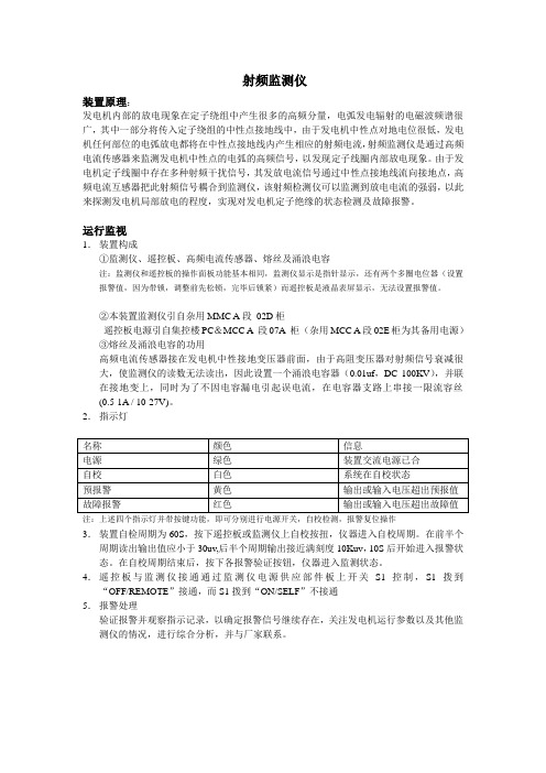
射频监测仪
装置原理:
发电机内部的放电现象在定子绕组中产生很多的高频分量,电弧发电辐射的电磁波频谱很广,其中一部分将传入定子绕组的中性点接地线中,由于发电机中性点对地电位很低,发电机任何部位的电弧放电都将在中性点接地线内产生相应的射频电流,射频监测仪是通过高频电流传感器来监测发电机中性点的电弧的高频信号,以发现定子线圈内部放电现象。
由于发电机定子线圈中存在多种射频干扰信号,其发放电流信号通过中性点接地线流向接地点,高频电流互感器把此射频信号耦合到监测仪,该射频检测仪可以监测到放电电流的强弱,以此来探测发电机局部放电的程度,实现对发电机定子绝缘的状态检测及故障报警。
运行监视
1.装置构成
①监测仪、遥控板、高频电流传感器、熔丝及涌浪电容
注:监测仪和遥控板的操作面板功能基本相同,监测仪显示是指针显示,还有两个多圈电位器(设置报警值,因为带锁,调整前先松锁,完毕后锁紧)而遥控板是液晶表屏显示,无法设置报警值。
②本装置监测仪引自杂用MMC A段02D柜
遥控板电源引自集控楼PC&MCC A 段07A 柜(杂用MCC A段02E柜为其备用电源)
③熔丝及涌浪电容的功用
高频电流传感器接在发电机中性接地变压器前面,由于高阻变压器对射频信号衰减很大,使监测仪的读数无法读出,因此设置一个涌浪电容器(0.01uf,DC 100KV),并联在接地变上,同时为了不因电容漏电引起误电流,在电容器支路上串接一限流容丝
(0.5-1A / 10-27V)。
2.指示灯
注:上述四个指示灯并带按键功能,即可分别进行电源开关,自校检测,报警复位操作
3.装置自检周期为60S,按下遥控板或监测仪上自校按扭,仪器进入自校周期。
在前半个周期读出输出值应小于30uv,后半个周期输出接近满刻度10Kuv,10S后开始进入报警状态。
在自校周期结束后,按下各报警验证按钮,仪器进入监测状态。
4.遥控板与监测仪接通通过监测仪电源供应部件板上开关S1控制,S1拨到“OFF/REMOTE”接通,而S1拨到“ON/SELF”不接通
5.报警处理
验证报警并观察指示记录,以确定报警信号继续存在,关注发电机运行参数以及其他监测仪的情况,进行综合分析,并与厂家联系。