cisco模拟实验
cisco Packet Tracer最真实的模拟VPN综合实验

PacketTracer 5.2的IPsec VPN先简单介绍下本文的模拟真实环境想法!本文是用Cisco PacketTracer5.2模拟器(软件下载见我博客的《PacketTrace 5.2的IPsec VPN实验说明(附PacketTracer 5.2下载地址)》)做的一个关于VPN的综合实验!其基本构想是这样的,最真实的模拟了ISP的DNS服务器,Web服务器(简单的讲这个直接挂在Internet网的Web服务器,就是我们常说的服务器在电信啊,网通啊等ISP托管的,日常维护这些服务器都是远程登入上去的!)。
用了一个AP来模拟移动无线网(你可以想象成我们常用的无线上网,如:GPRS,无线城域网,3G等。
简单点讲就是通过各种无线技术能上Internet网)。
至于Internet网的模拟嘛,还是我常说的没有私有IP路由表的路由器。
先让大家看看我的实验拓扑:实验的基本想法,配置思路和测试方法如下:(在附件中有本实验的PKT文件下载,大家可以按本文实验。
至于IPSEC VPN讲解和远程的Easy VPN我就不讲解了!大家见我的博客《PacketTracer 5.2的IPsec VPN实验说明(附PacketTracer 5.2下载地址)》和《Cisco PacketTracer 5.2模拟器的Easy VPN实验指南》)。
实验的IP规划如下:PC0 PC1 :DHCP获取笔记本:laptop0和wuxian:DHCP获取内部服务器:Web 192.168.1.253/24TFTP 192.168.1.252/24ISP服务器:ISP DNS 202.103.96.112/24ISP Web 202.103.96.120/24总部fa0/0:192.168.1.254/24fa0/1:100.1.1.2/24Internet网:fa0/1 :100.1.1.1/24fa 0/0:200.1.1.1/24E1/0:210.1.1.1/24(移动笔记本wuxian所获得公网地址段)E1/1:202.103.96.1/24(ISP DNS和ISP Web服务器的网关)分部:f0/0:200.1.1.2/24fa 0/1:192.168.2.254/24关于PacketTracer5.2中的服务器DNS和Web的配置以及PC和笔记本的配置和测试。
CISCO实验模拟器完全攻略
CISCO实验模拟器完全攻略Cisco在2002年新版的考试改革中,增加不少模拟实验题,大大提高考试难度。
从2003年Cisco考试的发展趋势来看,模拟实验题在考试中所占的比例越来越重。
为了配合Cisco考试类型的调整,国外不少专业认证考试公司推出各种各样的CISCO实验模拟器,比较出名的有思科网络学院FLASH版模拟实验器、Ro utersim和Boson 实验模拟器。
下面介绍互联网上流行的CISCO实验模拟器,让大家充分了解其特性,更好的进行选择适应自己的学习软件。
一、模拟器的种类:其实,模拟器的种类很多,其中大多数都能满足CCNA学习和考试需求。
适合CCNP的模拟实验环境就不多了。
现在流行的主要有:Routersim CCNA3.0、Routersim CCNPRouter_Simulator_v4.15Boson router simular 3.55Sybex CCNA Lab思科网络学院的flash练习思科网络学院的ccnp全套labs思科出品的Cisco Interactive Mentor(思科交互式学习指导CIM)二、模拟器的现状:现在的模拟器各有优点和缺点,都不是尽善尽美。
Routersim的特点完全是按照CCNA的实验设计的,如果学习NA的实验内容,routersim是很适合的。
实验教程分的很细致,讲解也很清楚,对于N A的学习者而言,是再好不过的了,它的最大缺点也正是由于完全局限于实验。
它的网络拓扑不能改变。
此主题相关图片如下:Routersim模拟器界面对于Boson的模拟器,它的最大优点就是能够自定义网络拓扑结构,而且在一般的范围下没有什么限制,可以模拟出你想要的实验环境,而不受实验教程的影响。
Boson的实验教程很少,而且还不全,一些考试所包含的内容没有。
比如在CCNP的实验中,只有BSCN的两个实验,然而有自定义拓扑的帮助,就可以很好的解决这个问题。
此主题相关图片如下:Boson模拟器界面思科学院的flash和labs还可以,至少从错误方面看(我相信绝对没有人愿意学习受误导的知识,如果是我,我宁愿没学过。
Cisco_Packet_Tracer实验教程

可以这么说,我用过有许多好的网络模拟软件,其中不乏有特别优秀的!比如Boson的Boson NetSim for CCNA 6.0就很优秀。
但是自从我用了Packet Tracer这个思科官方模拟软件后,我发现竟有更优秀的。
他的最新版本是Packet Tracer 5.0,直到现在我使用这个工具仍然是爱不释手,好了闲话不多说,工作!网络上有相关Packet Tracer的所谓“教程”,但是都只是皮毛,今天我从以下三个方面入手介绍Packet Tracer 5.0这个软件。
力求做到“深入、详解”。
另外我不反对大家转载这篇文章,但是我希望朋友转载后请注明链接:|狼人◇_传说/谢谢!本文用到的Packet Tracer有最新版本PT 5.2,下载地址:/files/1521bf9c-a187-11de-87fc-0014221b798a/cisco的Packet Tracer 5.2现已推出。
在原有5.1的基础上,增加了很多的安全特性。
现在5.2可以满足CCNA 安全课程的学习。
5.2增加的功能主要有:1、AAA2、加密功能2.1 点到点VPN2.2 远端VPN3、Qos (MQC的使用)4、NTP (网络时间协议)5、SNMP6、ipv67、ips8、路由协议也更加完善,可以实现的功能更加全面9、PC上也增加了几个新的功能是和路由器做配合。
第一篇、熟悉界面一、设备的选择与连接在界面的左下角一块区域,这里有许多种类的硬件设备,从左至右,从上到下依次为路由器、交换机、集线器、无线设备、设备之间的连线(Connections)、终端设备、仿真广域网、Custom Made Devices(自定义设备)下面着重讲一下“Connections”,用鼠标点一下它之后,在右边你会看到各种类型的线,依次为Automatically Choose Connection Type(自动选线,万能的,一般不建议使用,除非你真的不知道设备之间该用什么线)、控制线、直通线、交叉线、光纤、电话线、同轴电缆、DCE、DTE。
Cisco帧中继综合实验
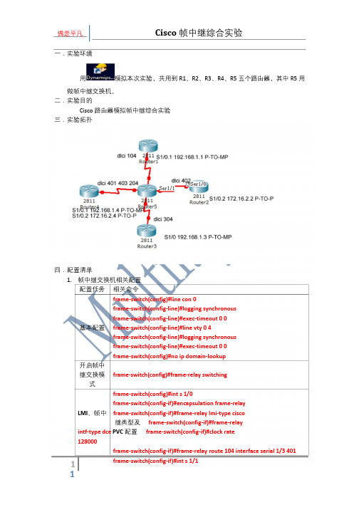
一.实验环境用模拟本次实验,共用到R1、R2、R3、R4、R5 五个路由器,其中R5 用做帧中继交换机。
二.实验目的Cisco 路由器模拟帧中继综合实验三.实验拓扑四.配置清单1. 帧中继交换机相关配置配置任务相关命令frame-switch(config)#line con 0frame-switch(config-line)#logging synchronousframe-switch(config-line)#exec-timeout 0 0基本配置frame-switch(config-line)#line vty 0 4frame-switch(config-line)#logging synchronousframe-switch(config-line)#exec-timeout 0 0frame-switch(config)#no ip domain-lookup开启帧中继交换模frame-switch(config)#frame-relay switching式frame-switch(config)#int s 1/0frame-switch(config-if)#encapsulation frame-relayLMI、帧中frame-switch(config-if)#frame-relay lmi-type cisco继类型及frame-switch(config-if)#frame-relayintf-type dce PVC 配置frame-switch(config-if)#clock rate128000frame-switch(config-if)#frame-relay route 104 interface serial 1/3 401frame-switch(config-if)#encapsulation frame-relayframe-switch(config-if)# frame-relay lmi-type ansiframe-switch(config-if)#frame-relay intf-type dceframe-switch(config-if)#clock rate 128000frame-switch(config-if)#frame-relay route 402 interface serial 1/3 204frame-switch(config-if)#int s 1/2frame-switch(config-if)#encapsulation frame-relayframe-switch(config-if)#frame-relay lmi-type ansiframe-switch(config-if)#frame-relay intf-type dceframe-switch(config-if)#clock rate 128000frame-switch(config-if)#frame-relay route 304 interface serial 1/3 403frame-switch(config-if)#int s 1/3frame-switch(config-if)#encapsulation frame-relayframe-switch(config-if)#frame-relay lmi-type ciscoframe-switch(config-if)#frame-relay intf-type dceframe-switch(config-if)#clock rate 128000frame-switch(config-if)#frame-relay route 401 interface serial 1/0 104frame-switch(config-if)#frame-relay route 403 interface serial 1/2 304frame-switch(config-if)#frame-relay route 204 interface serial 1/1 402 2. 帧中继网络路由器相关配置r1(config-if)#encapsulation frame-relayr1(config-if)#frame-relay intf-type dteR1 r1(config-if)#no shutdownr1(config)#int s 1/0.1 multipointr1(config-subif)#ip add 192.168.1.1 255.255.255.0r1(config-subif)#frame-relay map ip 192.168.1.4 104 broadcast r2(config)#int s 1/0R2 r2(config-if)#encapsulation frame-relay r2(config-if)# frame-relay lmi-type ansi r2(config-if)#frame-relay intf-type dteR3 r2(config)#int s 1/0.1 multipointr2(config-subif)#ip add 172.16.2.2 255.255.255.0r2(config-subif)#frame-relay interface-dlci 402r3(config)#int s 1/0r3(config-if)#encapsulation frame-relayr3(config-if)#frame-relay lmi-type ansir3(config-if)#no shutdownr3(config-if)#ip add 192.168.1.3 255.255.255.0r3(config-if)#frame-relay map ip 192.168.1.4 204 broadcast r4(config)#int s 1/0R4 r4(config-if)#encapsulation frame-relay r4(config-if)#frame-relay intf-type dte r4(config)#int s 1/0.1 multipointr4(config-subif)#ip add 192.168.1.4 255.255.255.0r4(config-subif)#frame-relay map ip 192.168.1.1 401 broadcastr4(config-subif)#frame-relay map ip 192.168.1.3 204 broadcastr4(config)#int s 1/0.2 point-to-pointr4(config-subif)#ip add 172.16.2.4 255.255.255.0r4(config-subif)#frame-relay interface-dlci 2043. 帧中继网络测试frame-switch#show frame-relay routeInput Intf Input Dlci Output Intf Output Dlci StatusSerial1/0 104 Serial1/3 401 activeSerial1/1 402 Serial1/3 204 activeSerial1/2 304 Serial1/3 403 activeSerial1/3 204 Serial1/1 402 activeSerial1/3 401 Serial1/0 104 activeSerial1/3 403 Serial1/2 304 active frame-switch#frame-switch#show frame-relay lmiLMI Statistics for interface Serial1/0 (Frame Relay DCE) LMI TYPE = CISCOInvalid Unnumbered info 0 Invalid Prot Disc 0Invalid dummy Call Ref 0 Invalid Msg Type 0Invalid Status Message 0 Invalid Lock Shift 0Invalid Information ID 0 Invalid Report IE Len 0Invalid Report Request 0 Invalid Keep IE Len 0Num Status Enq. Rcvd 475 Num Status msgs Sent 475Num Update Status Sent 0 Num St Enq. Timeouts 20LMI Statistics for interface Serial1/1 (Frame Relay DCE) LMI TYPE = ANSIInvalid Unnumbered info 0 Invalid Prot Disc 0Invalid dummy Call Ref 0 Invalid Msg Type 0Invalid Status Message 0 Invalid Lock Shift 0Invalid Information ID 0 Invalid Report IE Len 0Invalid Report Request 0 Invalid Keep IE Len 0Num Status Enq. Rcvd 313 Num Status msgs Sent 313Num Update Status Sent 0 Num St Enq. Timeouts 127LMI Statistics for interface Serial1/2 (Frame Relay DCE) LMI TYPE = ANSIInvalid Unnumbered info 0 Invalid Prot Disc 0Invalid dummy Call Ref 0 Invalid Msg Type 0Invalid Status Message 0 Invalid Lock Shift 0Invalid Information ID 0 Invalid Report IE Len 0Invalid Report Request 0 Invalid Keep IE Len 0Num Status Enq. Rcvd 295 Num Status msgs Sent 295Num Update Status Sent 0 Num St Enq. Timeouts 140LMI Statistics for interface Serial1/3 (Frame Relay DCE) LMI TYPE = CISCOInvalid Unnumbered info 0 Invalid Prot Disc 0Invalid dummy Call Ref 0 Invalid Msg Type 0Invalid Status Message 0 Invalid Lock Shift 0Invalid Information ID 0 Invalid Report IE Len 0Invalid Report Request 0 Invalid Keep IE Len 0Num Status Enq. Rcvd 199 Num Status msgs Sent 199Num Update Status Sent 0 Num St Enq. Timeouts 204frame-switch#frame-switch#show frame-relay pvcPVC Statistics for interface Serial1/0 (Frame Relay DCE)Active Inactive Deleted StaticLocal 0 0 0 0Switched 1 0 0 0Unused 0 0 0 0DLCI = 104, DLCI USAGE = SWITCHED, PVC STATUS = ACTIVE, INTERFACE = Serial1/0input pkts 10 output pkts 10 in bytes 1040out bytes 1040 dropped pkts 0 in pkts dropped 0out pkts dropped 0 out bytes dropped 0in FECN pkts 0 in BECN pkts 0 out FECN pkts 0out BECN pkts 0 in DE pkts 0 out DE pkts 0out bcast pkts 0 out bcast bytes 030 second input rate 0 bits/sec, 0 packets/sec30 second output rate 0 bits/sec, 0 packets/secswitched pkts 10Detailed packet drop counters:no out intf 0 out intf down 0 no out PVC 0in PVC down 0 out PVC down 0 pkt too big 0shaping Q full 0 pkt above DE 0 policing drop 0pvc create time 01:33:21, last time pvc status changed 00:34:29PVC Statistics for interface Serial1/1 (Frame Relay DCE)Active Inactive Deleted StaticLocal 0 0 0 0Switched 1 0 0 0Unused 0 0 0 0DLCI = 402, DLCI USAGE = SWITCHED, PVC STATUS = ACTIVE, INTERFACE = Serial1/1input pkts 40 output pkts 40 in bytes 9059out bytes 9266 dropped pkts 0 in pkts dropped 0out pkts dropped 0 out bytes dropped 0in FECN pkts 0 in BECN pkts 0 out FECN pkts 0out BECN pkts 0 in DE pkts 0 out DE pkts 0out bcast pkts 0 out bcast bytes 030 second input rate 0 bits/sec, 0 packets/sec30 second output rate 0 bits/sec, 0 packets/secswitched pkts 40Detailed packet drop counters:no out intf 0 out intf down 0 no out PVC 0in PVC down 0 out PVC down 0 pkt too big 0 shaping Q full 0 pkt above DE 0 policing drop 0pvc create time 01:31:22, last time pvc status changed 00:34:46PVC Statistics for interface Serial1/2 (Frame Relay DCE)Active Inactive Deleted StaticLocal 0 0 0 0Switched 1 0 0 0Unused 0 0 0 0DLCI = 304, DLCI USAGE = SWITCHED, PVC STATUS = ACTIVE, INTERFACE = Serial1/2input pkts 12 output pkts 8 in bytes 758out bytes 622 dropped pkts 0 in pkts dropped 0out pkts dropped 0 out bytes dropped 0in FECN pkts 0 in BECN pkts 0 out FECN pkts 0out BECN pkts 0 in DE pkts 0 out DE pkts 0out bcast pkts 0 out bcast bytes 030 second input rate 0 bits/sec, 0 packets/sec30 second output rate 0 bits/sec, 0 packets/secswitched pkts 12Detailed packet drop counters:no out intf 0 out intf down 0 no out PVC 0in PVC down 0 out PVC down 0 pkt too big 0 shaping Q full 0 pkt above DE 0 policing drop 0pvc create time 01:30:08, last time pvc status changed 00:34:43PVC Statistics for interface Serial1/3 (Frame Relay DCE)Active Inactive Deleted StaticLocal 0 0 0 0Switched 3 0 0 0Unused 0 0 0 0DLCI = 204, DLCI USAGE = SWITCHED, PVC STATUS = ACTIVE, INTERFACE = Serial1/3input pkts 41 output pkts 40 in bytes 9370out bytes 9059 dropped pkts 0 in pkts dropped 0out pkts dropped 0 out bytes dropped 0in FECN pkts 0 in BECN pkts 0 out FECN pkts 0out BECN pkts 0 in DE pkts 0 out DE pkts 0out bcast pkts 0 out bcast bytes 030 second input rate 0 bits/sec, 0 packets/sec30 second output rate 0 bits/sec, 0 packets/secswitched pkts 40Detailed packet drop counters:no out intf 0 out intf down 0 no out PVC 0in PVC down 0 out PVC down 0 pkt too big 0 shaping Q full 0 pkt above DE 0 policing drop 0pvc create time 01:27:03, last time pvc status changed 00:17:29DLCI = 401, DLCI USAGE = SWITCHED, PVC STATUS = ACTIVE, INTERFACE = Serial1/3input pkts 10 output pkts 10 in bytes 1040out bytes 1040 dropped pkts 0 in pkts dropped 0out pkts dropped 0 out bytes dropped 0in FECN pkts 0 in BECN pkts 0 out FECN pkts 0out BECN pkts 0 in DE pkts 0 out DE pkts 0out bcast pkts 0 out bcast bytes 030 second input rate 0 bits/sec, 0 packets/sec30 second output rate 0 bits/sec, 0 packets/secswitched pkts 10Detailed packet drop counters:no out intf 0 out intf down 0 no out PVC 0in PVC down 0 out PVC down 0 pkt too big 0 shaping Q full 0 pkt above DE 0 policing drop 0pvc create time 01:28:03, last time pvc status changed 00:35:00DLCI = 403, DLCI USAGE = SWITCHED, PVC STATUS = ACTIVE, INTERFACE = Serial1/3 input pkts 8 output pkts 12 in bytes 622out bytes 758 dropped pkts 0 in pkts dropped 0out pkts dropped 0 out bytes dropped 0in FECN pkts 0 in BECN pkts 0 out FECN pkts 0out BECN pkts 0 in DE pkts 0 out DE pkts 0out bcast pkts 0 out bcast bytes 030 second input rate 0 bits/sec, 0 packets/sec30 second output rate 0 bits/sec, 0 packets/secswitched pkts 8Detailed packet drop counters:no out intf 0 out intf down 0 no out PVC 0in PVC down 0 out PVC down 0 pkt too big 0shaping Q full 0 pkt above DE 0 policing drop 0pvc create time 01:27:49, last time pvc status changed 00:13:31 frame-switch#4. 网络连通性测试r4#ping 192.168.1.1Type escape sequence to abort.Sending 5, 100-byte ICMP Echos to 192.168.1.1, timeout is 2 seconds:!!!!!Success rate is 100 percent (5/5), round-trip min/avg/max = 404/463/556 msr4#ping 192.168.1.3Type escape sequence to abort.Sending 5, 100-byte ICMP Echos to 192.168.1.3, timeout is 2 seconds:!!!!!Success rate is 100 percent (5/5), round-trip min/avg/max = 400/404/408 msr4#ping 172.16.2.2Type escape sequence to abort.Sending 5, 100-byte ICMP Echos to 172.16.2.2, timeout is 2 seconds:!!!!!Success rate is 100 percent (5/5), round-trip min/avg/max = 292/352/424 ms r4#五.各设备全部配置r1#show running-configBuilding configuration...*Mar 1 01:55:06.315: %SYS-5-CONFIG_I: Configured from console by consoleCurrent configuration : 1256 bytes!version 12.4service timestamps debug datetime msecservice timestamps log datetime msec no service password-encryption!hostname r1!boot-start-markerboot-end-marker!!no aaa new-model!resource policy!memory-size iomem 5ip subnet-zeroip cef!!!!no ip domain lookup!!!!!!!!!!!!!!!!!!!!!interface FastEthernet0/0no ip addressshutdownduplex autospeed auto!interface FastEthernet0/1no ip addressshutdownduplex autospeed auto!interface Serial1/0no ip addressencapsulation frame-relayserial restart-delay 0no dce-terminal-timing-enable!interface Serial1/0.1 multipointip address 192.168.1.1 255.255.255.0frame-relay map ip 192.168.1.4 104 broadcast !interface Serial1/1no ip addressshutdownserial restart-delay 0no dce-terminal-timing-enable!interface Serial1/2no ip addressshutdownserial restart-delay 0no dce-terminal-timing-enable!interface Serial1/3no ip addressshutdownserial restart-delay 0no dce-terminal-timing-enable!ip classless!!ip http serverno ip http secure-server!!!!!control-plane!!!!!!!!!!line con 0exec-timeout 0 0logging synchronousline aux 0line vty 0 4exec-timeout 0 0logging synchronouslogin!!endr1#r2#show runBuilding configuration...Current configuration : 1310 bytes!version 12.4service timestamps debug datetime msecservice timestamps log datetime msecno service password-encryption!hostname r2!boot-start-markerboot-end-marker!!no aaa new-model!resource policy!memory-size iomem 5ip subnet-zeroip cef!!!!no ip domain lookup!!!!!!!!!!!!!!!!!!!!!interface FastEthernet0/0 no ip address shutdownduplex autospeed auto!interface FastEthernet0/1no ip addressshutdownduplex autospeed auto!interface Serial1/0no ip addressencapsulation frame-relayserial restart-delay 0no dce-terminal-timing-enable frame-relay lmi-type ansi!interface Serial1/0.2 point-to-point ip address 172.16.2.2 255.255.255.0 frame-relay interface-dlci 402!interface Serial1/1no ip addressshutdownserial restart-delay 0no dce-terminal-timing-enable!interface Serial1/2no ip addressshutdownserial restart-delay 0no dce-terminal-timing-enable!interface Serial1/3no ip addressshutdownserial restart-delay 0no dce-terminal-timing-enable!ip classless!!ip http serverno ip http secure-server!!!!!control-plane!!!!!!!!!!line con 0exec-timeout 0 0logging synchronousline aux 0line vty 0 4exec-timeout 0 0logging synchronouslogin!!endr2#r3#show running-configBuilding configuration...Current configuration : 1233 bytes!version 12.4service timestamps debug datetime msec service timestamps log datetime msec no service password-encryption!hostname r3!boot-start-markerboot-end-marker!!no aaa new-model!resource policy!memory-size iomem 5ip subnet-zeroip cef!!!!no ip domain lookup!!!!!!!!!!!!!!!!!!!!!interface FastEthernet0/0 no ip address shutdownduplex autospeed auto!interface FastEthernet0/1 no ip address shutdownduplex autospeed auto!interface Serial1/0ip address 192.168.1.3 255.255.255.0 encapsulation frame-relayserial restart-delay 0no dce-terminal-timing-enableframe-relay map ip 192.168.1.4 304 broadcast frame-relay lmi-type ansi!interface Serial1/1no ip addressshutdownserial restart-delay 0no dce-terminal-timing-enable!interface Serial1/2no ip addressshutdownserial restart-delay 0no dce-terminal-timing-enable!interface Serial1/3no ip addressshutdownserial restart-delay 0no dce-terminal-timing-enable!ip classless!!ip http serverno ip http secure-server!!!!!control-plane!!!!!!!!!!line con 0exec-timeout 0 0logging synchronousline aux 0line vty 0 4exec-timeout 0 0logging synchronouslogin!!endr3#r4#show runBuilding configuration...Current configuration : 1413 bytes!version 12.4service timestamps debug datetime msec service timestamps log datetime msec no service password-encryption!hostname r4!boot-start-markerboot-end-marker!!no aaa new-model!resource policy!memory-size iomem 5ip subnet-zeroip cef!!!!no ip domain lookup!!!!!!!!!!!!!!!!!!!!!interface FastEthernet0/0no ip addressshutdownduplex autospeed auto!interface FastEthernet0/1no ip addressshutdownduplex autospeed auto!interface Serial1/0no ip addressencapsulation frame-relayserial restart-delay 0no dce-terminal-timing-enable!interface Serial1/0.1 multipointip address 192.168.1.4 255.255.255.0frame-relay map ip 192.168.1.1 401 broadcast frame-relay map ip 192.168.1.3 403 broadcast !interface Serial1/0.2 point-to-pointip address 172.16.2.4 255.255.255.0frame-relay interface-dlci 204!interface Serial1/1no ip addressshutdownserial restart-delay 0no dce-terminal-timing-enable!interface Serial1/2no ip addressshutdownserial restart-delay 0no dce-terminal-timing-enable!interface Serial1/3no ip addressshutdownserial restart-delay 0no dce-terminal-timing-enable!ip classless!!ip http serverno ip http secure-server!!!!!control-plane!!!!!!!!!!line con 0exec-timeout 0 0logging synchronousline aux 0line vty 0 4exec-timeout 0 0logging synchronouslogin!!endr4#frame-switch#show runBuilding configuration...Current configuration : 1777 bytes!version 12.4service timestamps debug datetime msec service timestamps log datetime msec no service password-encryption!hostname frame-switch!boot-start-markerboot-end-marker!!no aaa new-model!resource policy!memory-size iomem 5ip subnet-zeroip cef!!!!no ip domain lookup!frame-relay switching!!!!!!!!!!!!!!!!!!!!interface FastEthernet0/0no ip addressshutdownduplex autospeed auto!interface FastEthernet0/1no ip addressshutdownduplex autospeed auto!interface Serial1/0no ip address encapsulation frame-relay serial restart-delay 0 clock rate 128000no dce-terminal-timing-enable frame-relay lmi-type cisco frame-relay intf-type dceframe-relay route 104 interface Serial1/3 401 !interface Serial1/1no ip addressencapsulation frame-relayserial restart-delay 0clock rate 128000no dce-terminal-timing-enableframe-relay lmi-type ansiframe-relay intf-type dceframe-relay route 402 interface Serial1/3 204 !interface Serial1/2no ip addressencapsulation frame-relayserial restart-delay 0clock rate 128000no dce-terminal-timing-enableframe-relay lmi-type ansiframe-relay intf-type dceframe-relay route 304 interface Serial1/3 403 !interface Serial1/3no ip addressencapsulation frame-relayserial restart-delay 0no dce-terminal-timing-enableframe-relay lmi-type ciscoframe-relay intf-type dceframe-relay route 204 interface Serial1/1 402 frame-relay route 401 interface Serial1/0 104 frame-relay route 403 interface Serial1/2 304 !ip classless!!ip http serverno ip http secure-server!!!!!control-plane!!!!!!!!!!line con 0exec-timeout 0 0 logging synchronous line aux 0line vty 0 4exec-timeout 0 0 logging synchronous login!!endframe-switch#。
packettracert简单实验教程
实验1 学习网络模拟平台一、实验目的掌握Cisco Packet Tracer软件的使用方法。
二、实验任务在Cisco Packet Tracer中用HUB组建局域网,利用PING命令检测机器的互通性。
三、实验设备集线器(HUB)一台,工作站PC三台,直连电缆三条。
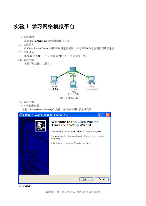
四、实验环境实验环境如图1-1所示。
图1-1 实验环境五、实验步骤(一)安装模拟器1、运行“PacketTracer53_setup”文件,并按如下图所示完成安装;点“NEXT”选择“I accept the agreement”后,点“next”不用更改安装目录,直接点“next”点“next”点“next”点“install”正在安装点“Finish”,安装完成进入到了模拟实验环境,请先关闭2、汉化:按“汉化说明”文件操作。
重启模拟器可看到如下图所示的汉化结果。
(二)使用模拟器1、运行Cisco Packet Tracer软件,在逻辑工作区放入一台集线器(HUB)和三台终端设备PC,用直连线(Copper Straight-Through)按下图将HUB和PC工作站连接起来,HUB端接Port口,PC端分别接以太网(Fastethernet)口。
2、分别点击各工作站PC,进入其配置窗口,选择桌面(Desktop)项,选择运行IP地址配置(IP Configuration),设置IP地址和子网掩码分别为PC0:1.1.1.1,255.255.255.0;PC1:1.1.1.2,255.255.255.0;PC2:1.1.1.3,255.255.255.0。
3、点击Cisco Packet Tracer软件右下方的仿真模式(Simulation Mode)按钮,如图1-2所示。
将Cisco Packet Tracer的工作状态由实时模式(Realtime)转换为仿真模式(Simulation)。
图1-2 按Simulation Mode按钮4、点击PC0进入配置窗口,选择桌面(Desktop)项,选择运行命令提示符(Command Prompt),如图1-3所示。
思科基于CiscoPT模拟器的防火墙配置实验案例详解
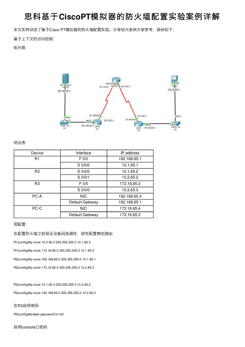
思科基于CiscoPT模拟器的防⽕墙配置实验案例详解本⽂实例讲述了基于Cisco PT模拟器的防⽕墙配置实验。
分享给⼤家供⼤家参考,具体如下:基于上下⽂的访问控制拓扑图地址表Device Interface IP addressR1 F 0/0192.168.65.1S 0/0/010.1.65.1R2S 0/0/010.1.65.2S 0/0/110.2.65.2R3 F 0/0172.16.65.3S 0/0/010.2.65.3PC-A NIC192.168.65.4Default Gateway192.168.65.1PC-C NIC172.16.65.4Default Gateway172.16.65.3预配置:在配置防⽕墙之前验证设备间连通性,即先配置静态路由R1(config)#ip route 10.2.65.0 255.255.255.0 10.1.65.2R1(config)#ip route 172.16.65.0 255.255.255.0 10.1.65.2R2(config)#ip route 192.168.65.0 255.255.255.0 10.1.65.1R2(config)#ip route 172.16.65.0 255.255.255.0 10.2.65.3R3(config)#ip route 10.1.65.0 255.255.255.0 10.2.65.2R3(config)#ip route 192.168.65.0 255.255.255.0 10.2.65.2在R3启⽤密码R3(config)#enable password lzr123启⽤console⼝密码R3(config)#line console 0R3(config-line)#password lzr123启⽤vty⾏接⼊密码R3(config)#line vty 0 4R3(config-line)#password lzr123把S1、S2所有交换机接⼝都在Vlan1(S2配置相同)S1(config)#int f 0/1S1(config-if)# switchport access vlan 1S1(config-if)# switchport trunk allowed vlan 1S1(config)#int f 0/2S1(config-if)# switchport access vlan 1S1(config-if)# switchport trunk allowed vlan 1预配置完成验证:在PC-C的命令提⽰符中ping PC-A服务器在PC-C命令提⽰符中telnet路由R2的s0/0/1接⼝:地址时10.2.65.2.退出telnet阶段在PC-C开⼀个⽹页浏览器登⼊PC-A来展⽰⽹页。
CISCO实验模拟器完全攻略
CISCO实验模拟器完全攻略CISCO实验模拟器是一种用于网络设备模拟的软件工具,它可以帮助用户在虚拟环境中进行网络配置和故障排除的实验。
本文将为大家介绍如何使用CISCO实验模拟器,并提供一些实用的技巧和建议。
第一部分:CISCO实验模拟器的基本介绍CISCO实验模拟器(Cisco Packet Tracer)是一款由思科公司开发的网络模拟软件,它可以模拟各种网络设备的工作原理和配置,包括交换机、路由器、防火墙等。
通过CISCO实验模拟器,用户可以在虚拟环境中进行网络实验,包括网络拓扑设计、配置设备、测试连通性等。
CISCO实验模拟器的界面简洁明了,操作简单易上手。
它提供了丰富的设备模板和工具,用户可以轻松地将设备拖拽到工作区进行配置。
此外,CISCO实验模拟器还支持实时的模拟和调试功能,用户可以在实验过程中查看设备的状态和性能信息,进行故障排除和优化。
第二部分:CISCO实验模拟器的使用方法1. 下载和安装CISCO实验模拟器首先,用户需要到思科官方网站下载和安装CISCO实验模拟器。
官方网站提供了各个版本的软件下载,用户可以选择适合自己操作系统的版本进行下载。
安装过程比较简单,按照提示进行操作即可。
2. 创建新项目打开CISCO实验模拟器后,首先需要创建一个新的项目来进行实验。
点击界面左侧的“新建项目”,然后输入项目名称和描述,点击“确定”即可创建一个新的项目。
3. 设计网络拓扑在项目中,用户可以通过拖拽设备模板来设计网络拓扑。
点击界面左侧的“设备”图标,选择需要的设备模板,然后将其拖拽到工作区。
用户可以根据自己的需求,连接各个设备并进行配置。
4. 配置设备在CISCO实验模拟器中,用户可以通过双击设备打开配置界面,进行设备的配置。
这包括设置IP地址、路由表、ACL 等。
用户可以根据实验要求进行相应的配置,然后保存设置。
5. 测试连通性在配置完成后,用户可以通过CISCO实验模拟器提供的工具测试网络的连通性。
实验四 cisco思科asa 模拟器 从内网访问DMZ服务器

实验四 ASA模拟器从内网访问DMZ区服务器配置(ASA模拟器)注意:本实验配置为用模拟器来实现,用来练习防火墙命令的使用,实现的功能和“实验四asa 5505 从内网访问DMZ服务器(真实防火墙)”相同,为了降低操作难度,我们只对ASA防火墙模拟器进行配置,完整的实验请参照“实验四asa 5505 从内网访问DMZ服务器(真实防火墙)”。
一、实验目标在这个实验中朋友你将要完成下列任务:1.用nameif命令给接口命名2.用ip address命令给接口分配IP3.用duplex配置接口的工作模式----双工(半双工)4.配置内部转化地址池(nat)外部转换地址globla二、实验拓扑三、实验过程1. ASA 模拟器基本配置:ciscoasa>ciscoasa> enablePassword:ciscoasa#ciscoasa# configure terminalciscoasa(config)# interface e0/2 *进入e0/2接口的配置模式ciscoasa(config-if)# nameif dmz *把e0/2接口的名称配置为dmzINFO: Security level for "dmz" set to 0 by default.ciscoasa(config-if)# security-level 50 *配置dmz 安全级别为50ciscoasa(config-if)# ip address 11.0.0.1 255.0.0.0 *给e0/2接口配置IP地址ciscoasa(config-if)# duplex auto *设置e0/2接口的工作模式为自动协商ciscoasa(config-if)# no shutdown *打开e0/2接口ciscoasa(config-if)# exit *退出e0/2接口的配置模式ciscoasa(config)#ciscoasa(config)# interface e0/0 *进入e0/0接口的配置模式ciscoasa(config-if)# nameif inside *把e0/0接口的名称配置为insideINFO: Security level for "inside" set to 100 by default.*安全级别取值范围为1~100,数字越大安全级别越高,在默认情况下,inside安全级别为100。
实验4-以太网的仿真组网及配置(cisco)
实验4-以太⽹的仿真组⽹及配置(cisco)实验4以太⽹的仿真组⽹及配置⼀、实验⽬的1.学会使⽤仿真软件Cisco Packet Tracer进⾏以太⽹的仿真组⽹和配置2.掌握交换机命令⾏各种操作模式的区别,以及模式之间的切换。
3.掌握交换机端⼝的常⽤配置命令4. 利⽤交换机进⾏VLAN的配置,加深对虚拟局域⽹⼯作原理的理解。
⼆、实验设备1.仿真软件Cisco Packet Tracer或Boson NetSim2.台式计算机三、技术原理1.交换机的管理交换机的管理⽅式基本分为两种:带内管理和带外管理。
管理员使⽤Telnet通过交换机的Console⼝管理交换机属于带外管理,不占⽤交换机的⽹络接⼝,其特点是需要使⽤配置线缆,近距离配置。
第⼀次配置交换机时必须利⽤Console端⼝进⾏配置。
交换机的命令⾏操作模式,主要包括:⽤户模式、特权模式、全局配置模式、端⼝模式等⼏种。
⽤户模式进⼊交换机后得到的第⼀个操作模式,该模式下可以简单查看交换机的软、硬件版本信息,并进⾏简单的测试。
⽤户模式提⽰符为switch> 特权模式由⽤户模式进⼊的下⼀级模式,该模式下可以对交换机的配置⽂件进⾏管理,查看交换机的配置信息,进⾏⽹络的测试和调试等。
特权模式提⽰符为switch# (注:switch>enable 命令进⼊特权模式)全局配置模式属于特权模式的下⼀级模式,该模式下可以配置交换机的全局性参数(如主机名、登录信息等)。
在该模式下可以进⼊下⼀级的配置模式,对交换机具体的功能进⾏配置。
全局模式提⽰符为switch(config)# (注:switch#configure terminal 命令进⼊全局配置模式)端⼝模式属于全局模式的下⼀级模式,该模式下可以对交换机的端⼝进⾏参数配置。
端⼝模式提⽰符为switch(config-if)# (注:switch(config)# interface fastethernet0/5 命令进⼊全局配置模式)Exit命令是退回到上⼀级操作模式。
Cisc0路由器模拟实验
Cisco路由器模拟实验实验一口令和主机名设置1.交换机的初始化当交换机没有进行配置时,接入超级终端会提示是否以对话方式进行配置,初始化内容主要有IP地址、网关、主机名和口令等。
配置文件是flash:config.text。
2924交换机进入ROM方式是在上电时按住其mode键,本软件是按Ctrl+Break键,出现:switch> ;按Ctrl+Break键switch:reset ;或用boot命令如果有配置文件进入用户模式,否则提交对话:--- System Configuration Dialog ---At any point you may enter a question mark '?' for help.Use ctrl-c to abort configuration dialog at any prompt.Default settings are in square brackets '[]'.Continue with configuration dialog? [yes/no]:yEnter IP address:10.65.1.8Enter IP netmask:255.255.0.0Would you like to enter a default gateway address? [yes]:IP address of default gateway:Enter host name [Switch]:swaThe enable secret is a one-way cryptographic secret usedinstead of the enable password when it exists.Enter enable secret:aaaWould you like to configure a Telnet password? [yes]:Enter Telnet password:aWould you like to enable as a cluster command switch? [no]:The following configuration command script was created:......Press RETURN to get started.swa>enpassword:aaaswa#copy run start (保存配置信息)swa#dir flash: (查看闪存中的文件)再次进入对话方式:swa#setup2.路由器的初始化路由器初始化与交换机类似,上电时按Ctrl+Break,进入ROM监控状态router> ;用户模式,按Ctrl+Break rommon>reset ;进入ROM监控状态,复位引导(没有配置文件或采用寄存器设置跳过配置文件提示对话信息)Continue with configuration dialog? [yes/no]:yesAt any point you may enter a question mark '?' for help.Use ctrl-c to abort configuration dialog at any prompt.Default settings are in square brackets '[ ]'.Basic management setup configures only enough connectivityfor management of the system,extended setup will ask youto configure each interface on the systemWould you like to enter basic management setup? [yes/no]:yesConfiguring global parameters:Enter host name [router]:ra回车The enable secret is a password used to protect access toprivileged EXEC and configuration modes. This password,after entered,becomes encrypted in the configuration.Enter enable secret:aaa回车The enable password is used when you do not specify anenable secret password,with some older software versions,and some boot images.Enter enable password:aa回车The virtual terminal password is used to protectaccess to the router over a network interface.Enter virtual terminal password :a回车Enter interface name used to connect to the managementnetwork from the above interface summary:FastEthernet0/0回车Configuring interface FastEthernet0/0:回车Use the 100 Base-TX (RJ-45) connector? [yes]:回车Operate in full-duplex mode? [no]:回车Configure IP on this interface? [yes]:回车IP address for this interface [ ]:10.1.1.1回车Subnet mask for this interface [ ]:255.0.0.0回车[0] Go to the IOS command prompt without saving this config.[1] Return back to the setup without saving this config.[2] Save this configuration to nvram and exit.Enter your selection [2]:回车ra>enpassword aaa (进入特权模式)ra#show run (显示配置信息)ra#w (保存配置信息)ra#dir flash: (显示配置文件)(配置文件在2621路由器不能删除,放弁配置文件要用寄存器设置0x2142);3. 用命令行设置交换机和路由器的口令和主机名交换机和路由器的口令和主机名的设置基本相同,在提问对话时,回答n,则进入命令行的状态。
有关思科模拟器实训总结范文

思科模拟器实训总结有关思科模拟器实训总结范文篇一:Cisco路由模拟器实验总汇实验一:1. 口令和设备名设置添加任意的交换机或路由器,先对交换机进行操作,双击SwitchA switch>enpassword: ;第一次密码为空,直接回车 switch#conf t ;进入全局配置模式switch(config)#hostname swa ;设置交换机名swa(config)#enable secret aaa;设置特权加密口令为aaa swa(config)#enable password aax ;设置特权非密口令为 aax swa(config)#line console 0;进入控制台口(Rs232)状态swa(config-line)#login ;允许登录swa(config-line)#password aa ;设置登录口令aaswa(config-line)#line vty 0 4;进入虚拟终端virtual tty swa(config-line)#login ;允许登录swa(config-line)#password a ;设置登录口令a swa(config-line)#exit ;返回上一层swa(config)#exit ;返回上一层swa#sh run ;看配置信息swa#exit;返回命令swa>enpassword: ;试验哪一个口令可以通过双击ROA对路由器进行与交换机类似的设置。
2. 清除口令清除交换机口令,实际中是在开机时按住交换机上的mode钮,本模拟机按Ctrl+Break清除路由器口令,参考如下:双击ROA 先配置路由的特权口令:router>enpassword: ;第一次密码为空,直接回车 router#conf t ;进入全局配置模式router(config)#enable secret aaa;设置特权加密口令为aaa router(config)#exit ;返回router#exitrouter>enpassword:aaarouter#清除口令是打开寄存器配置开关:router#reload ;重新启动,按Ctrl+Break rommon>rommon>confreg 0x2142 ;跳过配置,26xx 36xx 45xx rommon>reset;重新引导,等效于重开机 router>enpassword:router#conf trouter(config)#enable secret bbb;设置特权加密口令为aaa router(config)#config-register 0x2102 ;正常使用配置文件router(config)#exitrouter#exitrouter>enpassword:bbbrouter#实验二:计算机与交换机IP地址设置图文件:switch1规划ip地址:PCA: 10.65.1.1PCB: 10.65.1.2SWA: 10.65.1.31.双击PCA输入用户名:root输入口令:linux设置 IP :[root#PCA root]# ifconfig eth0 10.65.1.1 netmask 255.255.0.0查看 IP :[root#PCA root]# ifconfig删除IP : [root#PCA root]# ifconfig eth0 10.65.1.1 netamsk 255.255.0.0 down设置网关:[root#PCA root]# route add default gw 10.65.1.9 查看网关:[root#PCA root]# route删除网关:[root#PCA root]# route del default gw 10.65.1.92.双击PCB输入用户名:root输入口令:linux设置 IP :[root#PCB root]# ifconfig eth0 10.65.1.2 netmask 255.255.0.0设置网关:[root#PCB root]# route add default gw 10.65.1.93.双击SWA进入特权模式 : switch>en进入全局配置模式: switch#conf t进入默认VLAN状态: switch(config)#int vlan 1设置ip地址和掩码: switch(config-if)#ip address 10.65.1.3 255.255.0.0 设置switch的网关: switch(config)#ip defaule-gateway 10.65.1.9 查看设置 : #sh run4.回PCA[[email protected] root]# ping 10.65.1.1[[email protected] root]# ping 10.65.1.2[[email protected] root]# ping 10.65.1.35.修改PCB的ip地址修改为不同网段的一个ip地址,再从PCA Ping PCB。
用Cisco Packet Tracer模拟ADSL上网

用Cisco Packet Tracer模拟ADSL上网(2017-10-5)一、实验目的1. Cisco Packet Tracer模拟ADSL上网2.局端的配置3.DHCP配置4.ADSL的使用二、实验环境Cisco Packet Tracer模拟器三、实验拓扑四、实验步骤1.搭建拓扑2.配置局端MODE:3.配置客户端与服务器:客户端自动获取IP,服务器的IP地址如下:DNS配置如下:4.路由器R0配置如下:Router>enableRouter#configure terminalEnter configuration commands, one per line. End with CNTL/Z. Router(config)#hostname R0R0(config)#interface fastethernet 0/0R0(config-if)#ip address 192.168.1.1 255.255.255.0R0(config-if)#no shutdownR0(config-if)#interface serial 0/0R0(config-if)#ip address 172.16.12.1 255.255.255.252R0(config-if)#no shutdownR0(config-if)#exitR0(config)#ip dhcp pool POOL_1R0(dhcp-config)#network 192.168.1.0 255.255.255.0R0(dhcp-config)#dns-server 202.99.166.254R0(dhcp-config)#default-router 192.168.1.1R0(dhcp-config)#exitR0(config)#router ripR0(config-router)#version 2R0(config-router)#no auto-summaryR0(config-router)#network 192.168.1.0R0(config-router)#network 172.16.12.0R0(config-router)#exitR0(config)#5.路由器R1配置如下:Router>enableRouter#configure terminalEnter configuration commands, one per line. End with CNTL/Z. Router(config)#hostname R1R1(config)#interface fastethernet 0/0R1(config-if)#ip address 202.99.166.1 255.255.255.0R1(config-if)#no shutdownR1(config-if)#interface serial 0/0R1(config-if)#ip address 172.16.12.2 255.255.255.252R1(config-if)#no shutdownR1(config-if)#R1(config-if)#router ripR1(config-router)#version 2R1(config-router)#no auto-summaryR1(config-router)#network 202.99.166.0R1(config-router)#network 172.16.12.0R1(config-router)#exitR1(config)#6.验证1)查看客户端获IP地址情况2)查看对WEB服务的解析与访问情况。
实验一:Cisco模拟器静态路由实验

• 3、连线的时候注意,PC——交换机用直通线,交换机——路由器用直通 线,路由器——路由器用交叉线。
• 配置完毕后,首先测试PC能否连接各自网关
• 我们从左到右依次配置测试各设备 • 用PC1ping路由器A的fa1/0端口,看是否能ping通?
实验一:Cisco模拟器静态 路由实验
通过实现两台PC互联实验掌握路由的用法和原理
实验条件
• Cisco模拟器6.0(仿真实验)
一、组网:请按照下面图例组网并配置好端口的IP地址,并连线。
• 注意事项:
• 1、可以在路由器和PC间用交换机连接,因为在真实环境里,PC网卡速率 往往和路由器不匹配,无法直连,所以我们可以用交换机做一个中转(交 换机的端口一般都是自适应的,上可连路由器,下可连PC)。
上配置静态路由
• 继续验证,发现通了。
• 为什么通了?因为数据包到达C了,并且在上一个步骤,C已经通过静态路由知道要回复 192.168.1.101应该们先不做验证,我们自己推导一下: • 数据包能否到达D的fa0/0?当然可以,因为数据包能够到达C的fa1/0,并且D的fa0/0和C的fa1/0处于同一个
• 告诉ABCD,剩下两个网段11.0.0.0 10.0.0.0在哪里 • 因为D有11.0.0.0网段接口,并且刚才也配置了,所以不用配了 •A •B •C •D • 告诉E,192.168.1.0在哪里
• 可以看到,PC1能连接E的两个端口了
• 最后,可以看到PC1成功连通PC2
• 我们可以看看路由器的路由表,以C为例
• 可以看到,我们没做任何配置,PC可以连通和它不同网段的接口,为什么? • 因为,192.168.2.1和192.168.1.1在同一个路由器上,它们是同一个路由器的
(实例教程)CISCO模拟一看就会教程Cisco_Packet_Tracer

网路设备模拟器P a c k e t T r a c e r教程第一章认识PacketTracer软件PacketTracher介绍●PacketTracer是Cisco公司针对CCNA认证开发的一个用来设计、配置和故障排除网络的模拟软件。
●PackerTracer模拟器软件比Boson功能强大,比Dynamips操作简单,非常适合网络设备初学者使用。
学习任务1、安装PackerTracer;2、利用一台型号为2960的交换机将2pc机互连组建一个小型局域网;3、分别设置pc机的ip地址;4、验证pc机间可以互通。
实验设备Switch_29601台;PC2台;直连线PC1IP:Submask:Gateway:PC2IP:Submask:Gateway:PC1pingPC2 ReplyPC2pingPC1 ReplyPC2pingGateway Timeout第二章交换机的基本配置与管理实验目标●掌握交换机基本信息的配置管理。
实验背景●某公司新进一批交换机,在投入网络以后要进行初始配置与管理,你作为网络管理员,对交换机进行基本的配置与管理。
技术原理●交换机的管理方式基本分为两种:带内管理和带外管理。
●通过交换机的Console端口管理交换机属于带外管理;这种管理方式不占用交换机的网络端口,第一次配置交换机必须利用Console端口进行配置。
●通过Telnet、拨号等方式属于带内管理。
●交换机的命令行操作模式主要包括:●用户模式Switch>●特权模式Switch#●全局配置模式Switch(config)#●端口模式Switch(config-if)#实验步骤:●新建PacketTracer拓扑图●了解交换机命令行●进入特权模式(en)●进入全局配置模式(conft)●进入交换机端口视图模式(intf0/1)●返回到上级模式(exit)●从全局以下模式返回到特权模式(end)●帮助信息(如、co、copy)●命令简写(如conft)●命令自动补全(Tab)●快捷键(ctrl+c中断测试,ctrl+z退回到特权视图)●Reload重启。
- 1、下载文档前请自行甄别文档内容的完整性,平台不提供额外的编辑、内容补充、找答案等附加服务。
- 2、"仅部分预览"的文档,不可在线预览部分如存在完整性等问题,可反馈申请退款(可完整预览的文档不适用该条件!)。
- 3、如文档侵犯您的权益,请联系客服反馈,我们会尽快为您处理(人工客服工作时间:9:00-18:30)。
Packet Tracer 5.3建构CCNA实验攻略(1)——配置Cisco交换机Packet Tracer 5.3是一款非常不错的Cisco(思科)网络设备模拟器,对于想考思科初级认证(如CCNA)的朋友们来说,Packet Tracer 5.3是非常不错的选择。
通常我们周围并没有那么多思科的设备供我们学习调试,参加培训费用很贵,上机实践的机会还是有限的,利用Packet Tracer 5.3练习思科IOS操作命令很不错的。
近日,在网上下载了思科CCNA640-802指导用书,打算根据此教程与诸位网友共同分享Packet Tracer 5.3的使用方法与技巧,也借此抛砖引玉。
首先,要配置好Cisco交换必需要熟悉IOS命令及相关的知识。
一、几种配置命令模式switch>这种提示符表示是在用户命令模式,只能使用一些查看命令。
switch#这种提示符表示是在特权命令模式。
switch(config)# 这种提示符表示是全局配置模式switch(config-if)# 端口配置命令模式图一几种命令模式二、检查、查看命令这些命令是查看当前配置状况,通常是以show(sh)为开始的命令。
show version查看IOS的版本、show flash查看flash内存使用状况、show mac-address-table查看MAC地址列表图二图三图四图五Show ? 帮助命令显示当前所有的查看命令图六查看端口状态信息三、密码设置命令Cisco交换机、路由器中有很多密码,设置好这些密码可以有效地提高设备的安全性。
switch(config)#enable password 设置进入特权模式进的密码switch(config-line) 可以设置通过console端口连接设备及telnet远程登录时所需要的密码图七设置交换机的各种密码默认情况下,这些密码都是以明文的形式存储,所以很容易查看到。
为了避免这种情况,我们可以以密文的形式存储各种密码:service password-encryption图九图十密码以密文的形式存储四、配置IP地址及默认网关图十一五、管理MAC地址表switch#show mac-address-table 显示MAC地址列表switch#clear mac-address-table dynamic 清除动态MAC地址列表图十二图十三设置静态MAC地址六、配置端口安全switch(config-if)switchport port-securityswitch(config-if)switchport port-security maximum 4图十四图十五Packet Tracer 5.3建构CCNA实验攻略(2)——配置VLANPacket Tracer 5.3是一款非常不错的Cisco(思科)网络设备模拟器,对于想考思科初级认证(如CCNA)的朋友们来说,Packet Tracer 5.3是非常不错的选择。
通常我们周围并没有那么多思科的设备供我们学习调试,参加培训费用很贵,上机实践的机会还是有限的,利用Packet Tracer 5.3练习思科IOS操作命令很不错的。
近日,在网上下载了思科CCNA640-802指导用书,打算根据此教程与诸位网友共同分享Packet Tracer 5.3的使用方法与技巧,也借此抛砖引玉。
Vlan(Virtual Local Area Network)即虚拟局域网。
VLAN可以把同一个物理网络划分为多个逻辑网段,因此,Vlan可以抑制网络风暴,增强网络的安全性。
一、实例拓扑图图一交换机Cisco 2960二、创建VLAN在Cisco IOS中有两种方式创建vlan,在全局配置模式下使用vlan vlanid命令,如switch(config)#vlan 10;在vlan database下创建vlan,如switch(vlan)vlan 20图二创建vlan三、把端口划分给vlan(基于端口的vlan)switch(config)#interface fastethernet0/1 进入端口配置模式switch(config-if)#switchport mode access 配置端口为access模式switch(config-if)#switchport access vlan 10 把端口划分到vlan 10图三如果一次把多个端口划分给某个vlan可以使用interface range命令。
图四四、查看vlan信息switch#show vlan图五图六show vlan brief 查看vlan简明信息图七查看id为10的vlan图八通过vlan的名字查看vlan 五、删除配置图九把第0个模块中的第8个端口从vlan 40中删除图十删除vlan 40我们还可以为每个vlan配置ip地址。
Packet Tracer 5.3建构CCNA实验攻略(3)——Cisco VTPPacket Tracer 5.3是一款非常不错的Cisco(思科)网络设备模拟器,对于想考思科初级认证(如CCNA)的朋友们来说,Packet Tracer 5.3是非常不错的选择。
通常我们周围并没有那么多思科的设备供我们学习调试,参加培训费用很贵,上机实践的机会还是有限的,利用Packet Tracer 5.3练习思科IOS操作命令很不错的。
近日,在网上下载了思科CCNA640-802指导用书,打算根据此教程与诸位网友共同分享Packet Tracer 5.3的使用方法与技巧,也借此抛砖引玉。
VTP(Vlan Trunk Protocol)即VLAN中继协议。
VTP通过网络(ISL帧或cisco私有DTP 帧)保持VLAN配置统一性。
VTP在系统级管理增加,删除,调整的VLAN,自动地将信息向网络中其它的交换机广播。
此外,VTP减小了那些可能导致安全问题的配置。
便于管理,只要在vtp server做相应设置,vtp client会自动学习vtp server上的vlan信息。
一、实例拓扑图图一核心交换机Cisco 3560二、配置VTP核心交换机Cisco 3560配置为vtp Server,vtp domain为senya。
图二图三配置trunk链路,允许带vlan标记的以太网帧通过该链路图四配置汇聚层(接入层)交换机图五图六三、创建Vlan及端口划分图七在vtp server上创建vlan图八在vtp client上查看vlan图九划分端口四、配置pc及测试vlan图十为pc配置ip地址图十一本网段内互ping图十二为vlan配置ip地址图十三为pc配置网关图十四不同网段pc互相ping如果要限制不同网段的某些pc相互通信,可以使用访问控制列表进行控制。
Packet Tracer 5.3建构CCNA实验攻略(4)——STP生成树协议Packet Tracer 5.3是一款非常不错的Cisco(思科)网络设备模拟器,对于想考思科初级认证(如CCNA)的朋友们来说,Packet Tracer 5.3是非常不错的选择。
通常我们周围并没有那么多思科的设备供我们学习调试,参加培训费用很贵,上机实践的机会还是有限的,利用Packet Tracer 5.3练习思科IOS操作命令很不错的。
近日,在网上下载了思科CCNA640-802指导用书,打算根据此教程与诸位网友共同分享Packet Tracer 5.3的使用方法与技巧,也借此抛砖引玉。
STP的全称是spanning-tree protocol,STP协议是一个二层的链路管理协议,它在提供链路冗余的同时防止网络产生环路,与VLAN配合可以提供链路负载均衡。
生成树协议现已经发展为多生成树协议和快速生成树协议(RSTP,Rapid Spanning TreeProtocol,IEEE802.1W)。
一、配置实例拓扑图图一两台Cisco 2960交换机使用两个千兆端口相连,默认情况下STP协议启用的。
通过两台交换机之间传送BPDU协议数据单元,选出根交换机、根端口等,以便确定端口的转发状态。
上图中标记为黄色的端口处于block状态。
二、STP基本配置命令1、修改Brigde ID,重新选根网桥switch(config)#spanning-tree vlan 1 priority 4096图二图三根网桥改变,交换机端口的状态也发生了变化(与图一比较)switch(config-if)spanning-tree vlan vlan-id port-priority 优先级值交换机端口优先级值修改命令,通过修改端口优先值也可以更改端口的转发状态。
2、查看、检验STP(生成树协议)配置switch#show spanning-treeswitch#show spanning-tree activeswitch#show spanning-tree detailswitch#show spanning-tree interface interface-idswitch#show spanning-tree vlan vlanid图四三、STP与VLAN负载均衡配置图五配置负载均衡后,每个VLAN有自己的根网桥。
每条vlan中继链路只转发所允许的Vlan 数据帧。
switch(config-if)switchport trunk allowed vlan vlanid 这条命令配置某条trunk中继链路只能转发该vlan图六图七查看每个Vlan的STP状态switch(config)#spanning-tree vlan vlandid root primary 该命令配置某个vlan 的根网桥。
利用这个命令可以使用Vlan利用VTP进行负载均衡。
Packet Tracer 5.3建构CCNA实验攻略(5)——WLANPacket Tracer 5.3是一款非常不错的Cisco(思科)网络设备模拟器,对于想考思科初级认证(如CCNA)的朋友们来说,Packet Tracer 5.3是非常不错的选择。
通常我们周围并没有那么多思科的设备供我们学习调试,参加培训费用很贵,上机实践的机会还是有限的,利用Packet Tracer 5.3练习思科IOS操作命令很不错的。
近日,在网上下载了思科CCNA640-802指导用书,打算根据此教程与诸位网友共同分享Packet Tracer 5.3的使用方法与技巧,也借此抛砖引玉。
Packet Tracer 5.3对网络设备的模拟很真实,在Packet Tracer 5.3中操作与真实中操作设备几乎相当。
一、配置实例拓扑图图一拓扑图的说明:Packet Tracer 5.3中无线设备是Linksys WRT300N 无线路由器,该无线路由器共有四个RJ45插口,一个WAN口,四个LANEthernet口;计算机都配置有无线网卡模块,需要我们手动添加该无线网卡模块。
