Cisco路由模拟器实验总汇
实验报告路由器配置

实验二:路由器互连实验一、实验目的:1. 路由器1.、路由器2、路由器3互连。
2. 配置虚拟终端(telnet)。
二、实验要求:1.熟悉Cisco路由器模拟软件Cisco packet tracer的使用;2.利用该软件设计一个包含3个路由器、交换机的网络,网络拓扑、网络数量、路由器型号自定;3.根据所设计网络的结构,掌握网络规划方法。
三、实验步骤:1.首先在模拟器中构建出网络拓扑结构如下:2.在控制台微机的超级终端中分别配置路由器R1,R2,R3以下命令均以Router1为例配置主机名,配置模式口令格式如下:Router>enableRouter#config tRouter(config)#hostname Router1Router1(config)#enable secret 501Router1(config)#^Z配置接口(局域网和广域网)IP地址配置命令格式如下:Router1#config tRouter1(config)#int FastEthernet0/0Router1(config-if)#ip address 192.5.5.1 255.255.255.0Router1(config-if)#no shutdownRouter1(config-if)#^Z配置Router Rip协议命令格式如下:Router1#config tRouter1(config)#router ripRouter1(config-router)#network 192.5.5.0Router1(config-router)#network 201.100.11.0Router1(config-router)#^Z广域网接口协议配置命令格式如下:Router1#config tRouter1(config)#int Serial0/0/1Router1(config-if)#encapsulation hdlcRouter1(config-if)#bandwidth 64Router1(config-if)#^Z广域网接口时钟配置命令格式如下:Router1#config tRouter1(config)#int Serial0/0/1Router1(config-if)#clock rate 64000Router1(config-if)#^Z保存新的启动配置文件copy 命令格式如下:Router1#copy running-config startup-config路由器状态查看命令show常用格式如下:show interface[type slot/port]:该命令可以查看相关接口信息。
CISCO路由器PPPoE实验报告
CISCO路由器PPPoE实验报告题⽬:PPPOE实验实验拓扑如下:实验要求:1.在pppoe-client2路由器上使⽤NAT协议,让内部主机能够上⽹2.路由器pppoe-client2和pppoe-client1通过pppoe协议拨号连接pppoe-server服务器,3.在pppoe-server和ISP-router之间使⽤ospf路由选择协议实验⽬的:掌握1.pppoe在路由器上的配置过程2.NAT3.单区域ospf实验步骤:1.使⽤⼩凡模拟器搭建实验环境。
2.2.在pppoe-server 路由器上配置如下PPPoe-server(config-if)#username cisco password cisco 创建⼀个拨号帐号。
PPPoe-server(config)#vpdn enable //启⽤vpdn虚拟私有拨号⽹络协议PPPoe-server(config)#vpdn-group adsl0 //创建⼀个虚拟私有拨号⽹络组,起名为adsl0 PPPoe-server(config-vpdn)#accept-dialin //允许拨⼊改组PPPoe-server(config-vpdn-acc-in)#protocol pppoe //并启⽤pppoe协议%Only one PPPoE VPDN group can be configuredPPPoe-server(config-vpdn-acc-in)#virtual-template 1 //关联⼀个虚拟接⼝PPPoe-server(config-vpdn-acc-in)#exitPPPoe-server(config-vpdn)#pppoe limit per-mac 10 //限制拨号连接的mac数⽬为10PPPoe-server(config)#int f0/0 启⽤物理接⼝PPPoe-server(config-if)#ip add 1.1.1.1 255.255.255.0 配置ip地址PPPoe-server(config-if)#no shutPPPoe-server(config-if)#pppoe enable 并在该物理接⼝下启⽤pppoe协议PPPoe-server(config-if)#int virtual-template1 配置虚拟接⼝PPPoe-server(config-if)#ip address 200.0.0.1 255.255.255.0PPPoe-server(config-if)#peer default ip address pool ad 指定拨⼊端的iP池,名字为ad PPPoe-server(config-if)#pppauthentication chap pap callin 启⽤混合认证⽅式PPPoe-server(config-if)#ppp ipcp dns 202.102.128.68 202.102.134.68 给拨⼊端指派dns PPPoe-server(config-if)#ip local pool vt1 200.0.0.20 200.0.0.254 指定拨⼊端能够使⽤的ip范围PPPoe-server(config)#PPPoe-server(config)#router ospf 10 启⽤ospf路由选择协议PPPoe-server(config-router)#net 200.0.0.0 0.0.0.255 area 0 通告直连⽹络号PPPoe-server(config-router)#net 100.0.0.0 0.0.0.255 area 0PPPoe-server(config-router)#pppoe-server(config)#do sho ip rou ospf 查看ospf路由表5.0.0.0/32 is subnetted, 1 subnetsO 5.5.5.5 [110/11] via 100.0.0.2, 00:03:07, FastEthernet1/0pppoe-server(config)#pppoe-server(config)#do ping 5.5.5.5 测试Type escape sequence to abort.Sending 5, 100-byte ICMP Echos to 5.5.5.5, timeout is 2 seconds:Success rate is 100 percent (5/5), round-trip min/avg/max = 20/211/364 mspppoe-server(config)#do sho ip rou ospf5.0.0.0/32 is subnetted, 1 subnetsO 5.5.5.5 [110/11] via 100.0.0.2, 00:03:07, FastEthernet1/0pppoe-server(config)#在pppoe-client2上配置如下pppoe-client2(config)#vpdn enable 同上,在路由器作为拨⼊端时也要启⽤vpdn协议pppoe-client2(config)#int f0/0 pppoe-client2(config-if)#no shut 启⽤连接拨号的物理接⼝pppoe-client2(config-if)#*Mar 1 00:19:54.511: %LINK-3-UPDOWN: Interface FastEthernet0/0, changed state to up*Mar 1 00:19:55.511: %LINEPROTO-5-UPDOWN: Line protocol on Interface FastEthernet0/0, changed state to up pppoe-client2(config-if)#pppoe enable 同样启⽤pppoe协议pppoe-client2(config-if)#*Mar 1 00:20:56.283: %LINK-3-UPDOWN: Interface Virtual-Access1, changed state to up*Mar 1 00:20:57.283: %LINEPROTO-5-UPDOWN: Line protocol on Interface Virtual-Access1, changed state to up pppoe-client2(config-if)#pppoe-client dial-pool-number ?<1-255> Dialer pool numberpppoe-client2(config-if)#pppoe-client dial-pool-number 1 定义⼀个拨号池为1pppoe-client2(config-if)#exitpppoe-client2(config)#int dialer0 启⽤拨号接⼝pppoe-client2(config-if)#ip add negotiated ip地址协商pppoe-client2(config-if)#ip mtu 1492 默认mtu为1500由于pppoe包头占⽤8字节pppoe-client2(config-if)#no shutpppoe-client2(config-if)#encapsulation ppp 启⽤封装协议pppoe-client2(config-if)#ppp authentication chap pap callin 指定认证⽅式pppoe-client2(config-if)#ppp chap hostname ciscopppoe-client2(config-if)#ppp chap password ciscopppoe-client2(config-if)#ppp pap sent-username cisco password ciscopppoe-client2(config-if)#dialer pool 1 启⽤拨号池此时拨号⾃动开始连接pppoe-client2(config-if)#ppp ipcp dns request 请求获取dnspppoe-client2(config-if)#exitpppoe-client2(config)#int f0/0pppoe-client2(config-if)#ip add 2.2.2.2 255.255.255.0pppoe-client2(config-if)#no shutpppoe-client2(config-if)#exitpppoe-client2(config)#int f0/0pppoe-client2(config-if)#shutpppoe-client2(config-if)#*Mar 1 00:38:58.891: %LINK-5-CHANGED: Interface FastEthernet0/0, changed state to administratively down*Mar 1 00:38:59.891: %LINEPROTO-5-UPDOWN: Line protocol on Interface FastEthernet0/0, changed state to down pppoe-client2(config-if)#*Mar 1 00:39:55.127: %DIALER-6-UNBIND: Interface Vi2 unbound from profile Di0pppoe-client2(config-if)#*Mar 1 00:39:55.135: %LINK-3-UPDOWN: Interface Virtual-Access2, changed state to down pppoe-client2(config-if)# *Mar 1 00:39:56.115: %LINEPROTO-5-UPDOWN: Line protocol on Interface Virtual-Access2, changed state to down pppoe-client2(config-if)#pppoe-client2(config-if)#pppoe-client2(config-if)#no shutpppoe-client2(config-if)#*Mar 1 00:41:33.659: %LINK-3-UPDOWN: Interface FastEthernet0/0, changed state to up*Mar 1 00:41:34.659: %LINEPROTO-5-UPDOWN: Line protocol on Interface FastEthernet0/0, changed state to up pppoe-client2(config-if)#exi*Mar 1 00:41:50.519: %DIALER-6-BIND: Interface Vi2 bound to profile Di0pppoe-client2(config-if)#ex*Mar 1 00:41:50.527: %LINK-3-UPDOWN: Interface Virtual-Access2, changed state to up pppoe-client2(config-if)#pppoe-client2#^Zpppoe-client2#*Mar 1 00:41:54.491: %SYS-5-CONFIG_I: Configured from console by console*Mar 1 00:41:55.159: %LINEPROTO-5-UPDOWN: Line protocol on Interface Virtual-Access2, changed state to uppppoe-client2#sho ip int bri 获取到pppoe-server分配的ip地址,拨号成功Interface IP-Address OK? Method Status Protocol FastEthernet0/0 2.2.2.2 YES manual up up Ethernet1/0 unassigned YES unset administratively down down Ethernet1/1 unassigned YES unset administratively down down Ethernet1/2 unassigned YES unset administratively down down Ethernet1/3 unassigned YES unset administratively down down Virtual-Access1 unassigned YES unset up up Virtual-Access2 unassigned YES unset up up Dialer0 200.0.0.20 YES IPCP up up pppoe-client2#ping 200.0.0.1Type escape sequence to abort.Sending 5, 100-byte ICMP Echos to 200.0.0.1, timeout is 2 seconds:Success rate is 100 percent (5/5), round-trip min/avg/max = 8/175/392 mspppoe-client2#以下是为了内⽹主机能够通过pppoe-client来nat上⽹的配置。
思科模拟器单臂路由实验
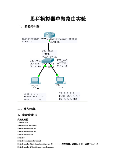
思科模拟器单臂路由实验一、实验拓扑图:二、操作步骤:1、实验步骤1:交换机配置Switch>enSwitch#vlan databaseSwitch(vlan)#vlan 10Switch(vlan)#vlan 20Switch(vlan)#exitSwitch#Switch#configure terminalSwitch(config)#interface fastEthernet 0/1------------连接电脑,设置为A口,承载VLAN 10 Switch(config-if)#switchport mode accessSwitch(config-if)#switchport access vlan 10Switch(config-if)#exitSwitch(config)#interface fastEthernet 0/2------------连接电脑,设置为A口,承载VLAN 20Switch(config-if)#switchport mode accessSwitch(config-if)#switchport access vlan 20Switch(config-if)#exiSwitch(config)#interface fastEthernet 0/3--------连接路由器,设置为T口,承载VLAN 10,20Switch(config-if)#switchport mode trunkSwitch(config-if)#switchport trunk allowed vlan 10,20Switch(config)#exitSwitch#wr路由器配置Router>enRouter#configure terminalRouter(config)#interface fastEthernet 0/0--------进入路由器0/0口Router(config-if)#no shutdown -------开启路由器0/0口Router(config-if)#exitRouter(config)#interface fastEthernet 0/0.1-------进入路由器0/0.1逻辑子接口Router(config-subif)#no shutdown -------开启路由器0/0.1口Router(config-subif)#encapsulation dot1Q 10 ---让路由器0/0.1逻辑子接口承载vlan10 Router(config-subif)#ip address 1.1.1.254 255.255.255.0----给路由器0/0.1逻辑子接口起IP地址(即PC4的网关)Router(config-subif)#exitRouter(config)#interface fastEthernet 0/0.2-------进入路由器0/0.2逻辑子接口Router(config-subif)#no shutdown -------开启路由器0/0.2口Router(config-subif)#encapsulation dot1Q 20---让路由器0/0.1逻辑子接口承载vlan20 Router(config-subif)#ip address 2.2.2.254 255.255.255.0-------给路由器0/0.2逻辑子接口起IP 地址(即PC5的网关)Router(config-subif)#exitRouter(config)#exitRouter#wr三、验证配置结果:在实验步骤3、实验步骤4完成后,分别验证结果:验证方法如下:1、PC4配置相应的IP地址和网关后,与PC5之间互相可以ping通;2、用show ip route观察交换机上的路由表,认识哪些是直连路由,哪些是静态路由信息,哪些是缺省路由;Router>show ip routeCodes: C - connected, S - static, I - IGRP, R - RIP, M - mobile, B - BGPD - EIGRP, EX - EIGRP external, O - OSPF, IA - OSPF inter areaN1 - OSPF NSSA external type 1, N2 - OSPF NSSA external type 2E1 - OSPF external type 1, E2 - OSPF external type 2, E - EGPi - IS-IS, L1 - IS-IS level-1, L2 - IS-IS level-2, ia - IS-IS inter area* - candidate default, U - per-user static route, o - ODRP - periodic downloaded static routeGateway of last resort is not set1.0.0.0/24 is subnetted, 1 subnetsC 1.1.1.0 is directly connected, FastEthernet0/0.12.0.0.0/24 is subnetted, 1 subnetsC 2.2.2.0 is directly connected, FastEthernet0/0.2。
Cisco实验大全CCNA实验大全

1. 设置计算机ip地址设置PCA的IP地址为:10.65.1.1 255.255.0.0 网关:10.65.1.2 设置PCB 的IP地址为:10.66.1.1 255.255.0.0 网关:10.66.1.2 设置ROA f0/0 IP为:10.65.1.2 255.255.0.0设置ROA f0/1 IP为:10.66.1.2 255.255.0.0设置计算机PCA的ip地址和网关的操作:[root@PCA root]# ifconfig eth0 10.65.1.1 netmask 255.255.0.0[root@PCA root]# ifconfig[root@PCA root]# route add default gw 10.65.1.2[root@PCA root]# route设置计算机PCB的ip地址和网关的操作:[root@PCB root]# ifconfig eth0 10.66.1.1 netmask 255.255.0.0[root@PCB root]# ifconfig[root@PCA root]# route add default gw 10.66.1.2[root@PCA root]# route2. 双击Router A,配置路由器的接口IP地址:router>enrouter#conf trouter(config)#hostname roaroa(config)int f0/0roa(config-if)#ip address 10.65.1.2 255.255.0.0roa(config-if)#no shutdown (默认是shutdown)roa(config-if)#exitroa(config)int f0/1roa(config-if)#ip address 10.66.1.2 255.255.0.0roa(config-if)#no shutroa(config)int s0/0roa(config-if)#ip address 10.67.1.2 255.255.0.0roa(config-if)#no shutroa(config-if)#clock rate 64000roa(config)int s0/1roa(config-if)#ip address 10.68.1.2 255.255.0.0roa(config-if)#no shutroa(config-if)#exitroa(config)#ip routing (默认是关闭的)3.检查网络联通情况[root@PCA root]# ping 10.65.1.2 (通) (ping自己的网关)[root@PCA root]# ping 10.66.1.2 (通) (ping f0/1)[root@PCA root]# ping 10.66.1.1 (通) (ping PCB)[root@PCA root]# ping 10.67.1.2 (不通) (端口空时down) [root@PCA root]# ping 10.68.1.2 (不通) (端口空时down)[root@PCB root]# ping 10.66.1.2 (通) (ping自己的网关) [root@PCB root]# ping 10.65.1.2 (通) (ping f0/0)[root@PCB root]# ping 10.65.1.1 (通) (ping PCA)[root@PCB root]# ping 10.67.1.2 (不通) (端口s0/0空时down) [root@PCB root]# ping 10.68.1.2 (不通) (端口s0/1空时down)roa#ping 10.65.1.1 (通) (ping PCA)roa#ping 10.65.1.2 (通) (ping f0/0)roa#ping 10.66.1.1 (通) (ping PCB)roa#ping 10.66.1.2 (通) (ping f0/1)roa#ping 10.67.1.2 (不通) (端口s0/0空时down)roa#ping 10.68.1.2 (不通) (端口s0/1空时down)下面我们做这个几个小实验:(1) 将路由器的接口f0/0关闭roa#conf troa(config)#int f0/0roa(config-if)#shutdownroa(config-if)#endroa#ping 10.65.1.2 (不通,端口down掉)roa#show int f0/0 (f0/0 is down,line proto is down) [root@PCA root]# ping 10.65.1.2 (不通)激活f0/0端口:roa(config)#int f0/0roa(config-if)#no shutroa(config-if)#endroa#ping 10.65.1.2 (通)去掉PCA与f0/0的连线roa#sh int f0/0 (f0/0 is up,line proto is down)roa#ping 10.65.1.2 (不通)roa#sh int s0/0 (s0/0 is down,line proto is down)roa#sh int s0/1 (s0/1 is down,line proto is down)serial口当没有连线时???(2) 关闭路由器的路由roa#conf troa(config)#no ip routing[root@PCA root]# ping 10.65.1.2 (通) (ping 自己的网关)[root@PCA root]# ping 10.66.1.1 (不通)(路由器不能转发了)[root@PCB root]# ping 10.66.1.2 (通) (ping 自己的网关)[root@PCB root]# ping 10.65.1.1 (不通)(路由器不能转发了)计算机可以ping与其相连的端口,但不能ping通下面的计算机,因为no ip routing后不具备转发的功能了。
思科路由部分11个实验项目
思科路由部分11个实验项目:全程记录+讲解+知识点思科路由部分11个实验项目:全程记录+讲解+知识点实验基于Dynamips-0.2.6-Rc4 | unzip-c3620-i-mz.122-37.bin |unzip-c3640-js-mz.124-10 with NM-16ESW实验平台双Xeon 3.0 4G ECC 运行稳定后CPU 40%左右实验1:在P1范围内实现RIPv2实验2:在P1范围内实现基于RIPv2的等价负载均衡实验3:在P1范围内实现基于RIPv2的Key-Chain密钥实验实验4:在P2范围内实现IGRP的非等价负载均衡实验5:全区域中通过桢中继实现RIPv2路由协议 + 密钥验证实验6:全区域中实现EIGRP路由+FR+非等价负载均衡+验证实验7:OSPF基本配置[P1区域内配置]+DR/BDR考察实验8:单区域NBMA环境OSPF实现+验证实验9:多区域OSPF实现实验10:简单的路由重发布末节区域完全末节区域 NSSA区域 Virtual-Link实验11:被动接口路由更新过滤策略路由路由单项重发布以及AD/Metric更改路由双向重发布P1配置部分P1R1-P1R2192.168.1.1 - 192.168.1.2 /24 P1R1上配置Lo0 200.200.200.200 /24 P1R1-P1R3192.168.2.1 - 192.168.2.2 /24P1R3-P1R4192.168.3.1 - 192.168.3.2 /24P1R2-P1R4192.168.4.1 - 192.168.4.2 /24P1R1-BBR1 - 10.0.0.2 /8P1R2-BBR1 - 10.0.0.3 /8P2配置部分P2R1-P2R2172.16.1.1 - 172.16.1.2 /16 P2R1上配置Lo0 100.100.100.100 /8 P2R1-P2R3172.17.1.1 - 172.17.1.2 /16P2R3-P2R4172.18.1.1 - 172.18.1.2 /16P2R2-P2R4172.19.1.1 - 172.19.1.2 /16P2R1-BBR2 - 11.0.0.2 /8P2R2-BBR2 - 11.0.0.3 /8BBR配置部分BBR1-BBR2219.146.241.1 -219.146.241.2 /24BBR1 s0/0.1 -s0/0.210.0.0.1BBR2 s0/0.1 -s0/0.211.0.0.1BBR2-SW1219.146.242.1 - 219.146.242.2BBR1-SW2219.146.243.1 - 219.146.243.2SW1-SW2219.146.244.1 - 219.146.244.2SR配置部分SR1-SW1 101.0.0.1 - 101.0.0.2SR2-SW1 102.0.0.1 - 102.0.0.2SR3-SW2 103.0.0.1 - 103.0.0.2SR4-SW2 104.0.0.1 - 104.0.0.2SR1:lo0 105.0.0.1 Lo1 106.0.0.1SR2:lo0 107.0.0.1 Lo1 108.0.0.1实验1:在P1范围内实现RIPv2[P1R1]router ripver 2net 192.168.1.0net 192.168.2.0net 200.200.200.0[P1R2]router ripver 2net 192.168.1.0net 192.168.4.0[P1R3]router ripver 2net 192.168.2.0net 192.168.3.0[P1R4]router ripver 2net 192.168.3.0net 192.168.4.0验证结果,P1R1[Copy to clipboard]CODE:sh ip route:C 200.200.200.0/24 is directly connected, Loopback0R 192.168.4.0/24 [120/2] via 192.168.2.2, 00:00:22, FastEthernet0/0C 192.168.1.0/24 is directly connected, Serial1/1C 192.168.2.0/24 is directly connected, FastEthernet0/0R 192.168.3.0/24 [120/1] via 192.168.2.2, 00:00:22, FastEthernet0/0 注意:区分RIP两个版本,配置时候必须配置相同的rip version,虽然有办法让他们协同工作,但是基本上没什么意义RIPV1分类路由,没30秒发送一次更新分组,分组中不包含子网掩码信息,不支持 VLSM,默认进行边界自动路由汇总,且不可关闭,所以该路由不能支持非连续网络.不支持身份验证. 使用跳数作为度量,管理距离 120.每个分组中最多只能包含25个路由信息.使用广播进行路由更新.RIPV2无类路由,发送分组中含有子网掩码信息,支持VLSM,但默认该协议开启了自动汇总功能,所以如需向不同主类网络发送子网信息,需要手工关闭自动汇总功能(no auto-summary),RIPV2只支持将路由汇总至主类网络,无法将不同主类网络汇总,所以不支持CIDR.使用多播224.0.0.9进行路由更新,只有对应的多播MAC地址能够响应分组,在MAC层就能区分是否对分组响应.支持身份验证.分类路由选择协议,当发送路由分组的接口所处子网与分组相关的子网属于同一主类网络,那么路由器在该接口可以把具体的子网发送出去.路由器假设该接口与分组子网使用相同的子网掩码.什么是连续子网:属于同一主类网络,使用相同的子网掩码就是连续的子网.否则就是非连续子网.在接口上手工汇总命令:ip summary-address rip 被汇总子网被汇总子网掩码RIP 使用UDP(用户报文协议)520端口传输路由更新分组RIP只能做等价负载均衡实验2 在P1范围内实现基于RIPv2的等价负载均衡P1R1上的Lo0为200.200.200.200,作为此实验的目的IP[P1R4]int f0/0no ip route-cacheint s1/0no ip route-cacheaccess-list 101 permit ip icmp any 200.200.200.0 0.0.0.255debug ip pac 101验证结果[P1R2]router ripver 2net 192.168.1.0net 192.168.4.0[P1R3]router ripver 2net 192.168.2.0net 192.168.3.0[P1R4]router ripver 2net 192.168.3.0net 192.168.4.0P1R4上sh ip route,可以看到[Copy to clipboard]CODE:Gateway of last resort is not setR 200.200.200.0/24 [120/2] via 192.168.4.1, 00:00:16, FastEthernet0/0 [120/2] via 192.168.3.1, 00:00:09, Serial1/0C 192.168.4.0/24 is directly connected, FastEthernet0/0R 192.168.1.0/24 [120/1] via 192.168.4.1, 00:00:16, FastEthernet0/0 R 192.168.2.0/24 [120/1] via 192.168.3.1, 00:00:09, Serial1/0C 192.168.3.0/24 is directly connected, Serial1/0到达200.200.200.0网段的metric完全相同,并且通过两个出口P1R4#ping 200.200.200.200 re 2[Copy to clipboard]CODE:Type escape sequence to abort.Sending 2, 100-byte ICMP Echos to 200.200.200.200, timeout is 2 seconds:!!Success rate is 100 percent (2/2), round-trip min/avg/max = 12/14/16 msP1R4#16:00:24: IP: tableid=0, s=192.168.4.2 (local), d=200.200.200.200 (FastEthernet0/0), routed via RIB16:00:24: IP: s=192.168.4.2 (local), d=200.200.200.200 (FastEthernet0/0), len 100, sending16:00:24: IP: tableid=0, s=192.168.3.2 (local), d=200.200.200.200 (Serial1/0), routed via RIB16:00:24: IP: s=192.168.3.2 (local), d=200.200.200.200 (Serial1/0), len 100, sending注意1.route-cache是进程交换, ip route-cache是快速交换, ip route-cache optimum是最优交换, route-cache distributed是分布式最优,负载均衡需要切换为进程交换(根据分组处理,而不是目的地),7000以上系列需要no ip cef2.通过定义ACL定义过滤,然后debug抓取特定的数据包,可以最优化显示debug结果均衡负载的知识:均衡负载可以是基于目标地址或者是基于每个packet的所谓基于目标地址的均衡负载,是说假如有2条到达目标地址的路径,那么第一个packet将通过第一条链路到达第一个目标设备,第二个packet将通过第二条链路到达第二个目标设备,第三个packet又将通过第一条链路到达第三个目标设备等等,以次类推.当Cisco路由器工作在默认的交换模式,Fast Switching(快速交换)模式下,就使用这种类型的均衡负载 Fast Switching的工作原理是:当路由器对第一个packet进行发往目标地址的处理的时候,先查看路由表和选择出口接口,然后获取组成 frame的信息(比如ARP表的查询)并进行封装,然后传输.之前获取的这些路由和数据链路信息将被保存在快速交换的cache中.接下来,当有要到达和第一个包相同的目标地址的包的时候,就可以不进行路由表和ARP表的查询,直接对packet进行交换快速交换降低了CPU的占用和处理时间,并意味着去往某个目标地址的packet都从相同的路由器接口被路由出去.当有到达同一网络不同主机的packet,路由器可能会吧这些packet通过另外一条链路进行路由.因此,路由器能做的最好的就是给予目标地址的均衡负载所谓基于基于packet的均衡负载,是说假如有2条到达目标地址的路径,那么第一个packet将通过第一条链路到达目标设备,第二个packet将通过第二条链路到达目标设备,第三个packet又将通过第一条链路到达目标设备等等,以次类推.(这里考虑的是等价的均衡负载) Cisco路由器工作在Process Switching(进程交换)模式的时候就采用基于packet的均衡负载进程交换,是指每次对packet的交换,都要查询路由表,选择出口接口和查询数据链路信息,因为每次的路由决策都是独立的.要在某个接口打开进程交换模式,使用no ip route-cache命令.实验3 在P1范围内实现基于RIPv2的Key-Chain密钥实验 [P1R1]key chain ciscokey 1key-string mypasswordint f0/0ip rip auth key-chain ciscoip rip auth mode md 5int s1/1ip rip auth key-chain ciscoip rip auth mode md5验证结果在P1R1上定义密钥以后,分别在s1/1和f0/0上面启用,在其他路由器并没有启用相同的密钥的时候,通过debug ip rip eve查看:16:18:45: RIP: ignored v2 packet from 192.168.1.2 (invalid authentication)sh ip route查看R 192.168.3.0/24 is possibly down, routing via 192.168.2.2, FastEthernet0/0 说明因为密钥匹配原因,packet ignored,并且路由条目状态变化为possibly down在P1R2上定义同样密钥后debug 信息显示Page 5 of Cisco Tec! - Powered by Discuz! Board 31P1R4上sh ip route,可以看到16:31:16: RIP: received packet with MD5 authentication认证成功附加部分在P1R2上采用同样密钥,但是在接口上应用的时候如果采用明文方式 ip rip auth mod text(P1R1采用MD5加密)因为两边不匹配,则一样会invalid authentication注意可以在路由器上配置RIPv2消息认证包括:明文或MD5加密密码在钥匙链(key-chain)上定义多个秘钥(key)或密码,后者可选定义秘钥链名称:key chain test定义秘钥 key 1定义密码key-string cisco在接口上启用 int e0/0 ip rip authentication key-chain test定义发送方式 ip rip authtication mode md5记住,钥匙链-钥匙-钥匙的凹凸代表密码,必须在个锁(接口)上使用此钥匙(引用)sh ip pro可以查看version和keychain情况Default version control: send version 2, receive version 2 Interface Send Recv Triggered RIP Key-chain FastEthernet0/0 2 2 ciscoSerial1/1 2 2 ciscoLoopback0 2 2实验4 在P2范围内实现IGRP的非等价负载均衡等价负载均衡同RIP部分,设置上没什么特殊之处[P2R4]int f0/0bandwidth 10000no ip route-cacheint s1/0bandwidth 1000no ip route-cacherouter igrp 100vari 10access-list 101 permit ip icmp any 100.100.100.0 0.0.0.255debug ip pac 101验证结果使用sh int f0/0察看其默认BW为BW 100000 Kbit使用sh int s1/0察看其默认BW为BW 1544 Kbit但是奇怪的是,我还没有设置variance,且BW不同的情况下,基于Dynamips的metric计算值竟然相同,先不管它I 100.0.0.0/8 [100/8986] via 172.19.1.1, 00:00:09, FastEthernet0/0[100/8986] via 172.18.1.1, 00:00:18, Serial1/0如果只是设置了带宽,则所有的pac将从f0/0发出[Copy to clipboard]CODE:P2R4#ping 100.100.100.100 re 2Type escape sequence to abort.Sending 2, 100-byte ICMP Echos to 100.100.100.100, timeout is 2 seconds:!!Success rate is 100 percent (2/2), round-trip min/avg/max = 12/14/16 msP2R4#00:54:07: IP: tableid=0, s=172.19.1.2 (local), d=100.100.100.100 (FastEthernet0/0), routed via RIB00:54:07: IP: s=172.19.1.2 (local), d=100.100.100.100 (FastEthernet0/0), len 100, sending00:54:07: IP: tableid=0, s=172.19.1.2 (local), d=100.100.100.100 (FastEthernet0/0), routed via RIB00:54:07: IP: s=172.19.1.2 (local), d=100.100.100.100 (FastEthernet0/0), len 100,sending16:31:16: RIP: received packet with MD5 authentication认证成功附加部分在P1R2上采用同样密钥,但是在接口上应用的时候如果采用明文方式 ip rip auth mod text(P1R1采用MD5加密)因为两边不匹配,则一样会invalid authentication设置好variance以后,sh ip routeI 100.0.0.0/8 [100/8986] via 172.19.1.1, 00:01:09, FastEthernet0/0[100/12510] via 172.18.1.1, 00:00:16, Serial1/0两条路出来了,然后观察抓包即可[Copy to clipboard]CODE:P1R4#ping 100.100.100.100 re 2Type escape sequence to abort.Sending 2, 100-byte ICMP Echos to 100.100.100.100, timeout is 2 seconds:!!Success rate is 100 percent (2/2), round-trip min/avg/max = 12/14/16 msP1R4#00:58:24: IP: tableid=0, s=172.19.1.1 (local), d=100.100.100.100 (FastEthernet0/0), routed via RIB00:58:24: IP: s=172.19.1.1 (local), d=100.100.100.100 (FastEthernet0/0), len 100, sending00:58:24: IP: tableid=0, s=172.18.1.1 (local), d=100.100.100.100 (Serial1/0), routed via RIB00:58:24: IP: s=172.18.1.1 (local), d=100.100.100.100 (Serial1/0), len 100, sending注意:设置BW中的两个错误1.将两个BW值一个500000 一个1500,设置variance 为 334,5000000/1500=333,但是经过实验,variance设置范围为1-1282.设置BW值不适当的时候,可能会导致sh ip route显示possiblydown,这个时候重新启用IGRP即可知识点:IP协议出现最早,最大跳数只支持15跳,只适合小型网络;IGRP是Cisco公司为了弥补RIP的缺陷而开发设计,适合更大的网络,最大支持255跳,为了减轻网络的负担,将默认的更新周期从RIP的30秒改为90秒,但是这也造成了网络拓扑变化时收敛速度变迟缓了。
思科模拟器试验步骤.概要
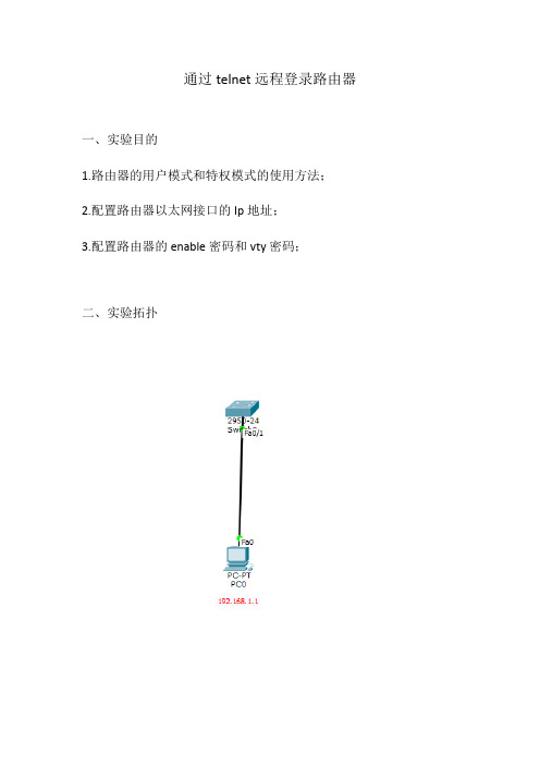
通过telnet远程登录路由器一、实验目的1.路由器的用户模式和特权模式的使用方法;2.配置路由器以太网接口的Ip地址;3.配置路由器的enable密码和vty密码;二、实验拓扑三、实验步骤第一步:按照拓扑图搭建实验环境;第二步:实验步骤;(1)步骤一:配置路由器以太网接口IP地址;1、交换机上基本操作Switch>enable \\进入全局模式Switch#conf t \\进入特权模式Switch(config)#interface vlan 1 \\进入端口Switch(config-if)#ip address 192.168.1.10 255.255.255.0 \\配置IP地址Switch(config-if)#no shutdown \\打开端口Switch(conffig-if)#exit \\回到上一步2、配置虚拟终端密码Switch(config)#line vty 0 4 \\进入vty虚拟终端Switch(config-line)#password 123 \\配置telnet密码Switch(config-line)#login \\注册Switch(config-line)#exit \\回到上一级模式下四、实验调试(1)通过telnet访问路由器在计算机配置网卡的IP地址为192.168.1.1/255.255.255.0,并打开DOS命令行窗口。
首先测试计算机和路由器的IP连通性,在进行Telnet远程登录。
如下:Ping statistics for 192.168.1.10:Packets: Sent = 4, Received = 0, Lost = 4 (100% loss),PC>ping 192.168.1.10Pinging 192.168.1.1 with 32 bytes of data:Request timed out.Reply from 192.168.1.10: bytes=32 time=0ms TTL=255Reply from 192.168.1.10: bytes=32 time=0ms TTL=255Reply from 192.168.1.10: bytes=32 time=0ms TTL=255Ping statistics for 192.168.1.10:Packets: Sent = 4, Received = 3, Lost = 1 (25% loss),Approximate round trip times in milli-seconds:Minimum = 0ms, Maximum = 0ms, Average = 0ms//以上表明计算机能ping通路由器接口fastethernet0/1的IP地址PC>telnet 192.168.1.10 //从计算机telnet路由器以太网卡上的IP地址Trying 192.168.1.10 ...OpenUser Access VerificationPassword:Switch>enablePassword:Switch#//输入vty的密码123、输入enable的密码456,能正常进入路由器的特权模式。
基于Cisco Packet Tracer的路由交换综合实验设计
基于Cisco Packet Tracer的路由交换综合实验设计
一、实验目的
本次实验的目的是通过Cisco Packet Tracer模拟网络环境,进行路由交换的综合实验,以加深对路由器配置和交换机互联的理解,提高实际操作技能。
二、实验环境
1. 软件准备:Cisco Packet Tracer软件
2. 设备准备:2台路由器、3台交换机、若干台电脑
三、实验内容
1. 实验一:路由器基本配置
步骤:
1)在Packet Tracer中拖动两台路由器到画布上,连接它们之间的Seria接口。
2)通过CLI界面对路由器进行基本配置,包括主机名、密码、IP地址、路由协议等。
3)通过ping测试和show命令验证路由器配置是否正确。
四、实验总结
通过以上实验,我们可以掌握路由器和交换机的基本配置方法、互联配置方法以及静态路由和动态路由的配置方法。
在实际工作中,我们需要根据网络规模和需求来选择合适的配置方式,以保障网络的稳定和高效运行。
五、注意事项
1. 在进行实验前,务必熟悉Cisco Packet Tracer的基本操作方法,了解设备的拓扑图和CLI配置界面。
2. 实验中涉及到的命令和配置方法,需要进行充分的练习和理解,避免因配置错误导致网络通信异常。
3. 在进行实验时,可以根据需要进行功能扩展,如配置DHCP服务、访问控制列表等,以提高实验的综合性和实用性。
通过本文的介绍,我们了解了基于Cisco Packet Tracer的路由交换综合实验的设计内容和步骤。
这些实验内容对于提升路由交换技术的实际操作能力和解决网络故障具有重要意义,希望读者能够通过实践不断提升自己的技能水平。
思科模拟器交换机与路由器配置实验汇总

99的数字表示 permit 172.16.1.0 0.0.0.255 deny 172.16.2.0 0.0.0.255 (如果有上面的permit默认跟一个deny,所
以此命令可不写) conf t int s0/0/0 //标准访问控制列表要尽量靠近目的端,相反地,拓展访问
关键命令行: conf t router rip network 192.168.1.0 network 192.168.3.0 //与该路由直接相连的网段 version 2
OSPF动态路由配置
OSPF(Open Shortest Path First开放式最短路径优先)是目前网路中 应用最广泛的路由协议之一。属于内部网管路由协议,能够适应各种规模 的网络环境,是典型的链路状态协议。OSPF路由协议通过向全网扩散本设 备的链路状态信息,使网络中每台设备最终同步一个具有全网链路状态的 数据库,然后路由器采用SPF算法,以自己为根,计算到达其他网络的最 短路径,最终形成全网路由信息。
占用交换机的网络端口,第一次配置交换机必须利用Console端口进行配置。 通过Telnet、拨号等方式属于带内管理。
交换机命令行 1、进入特权模式(en) 2、进入全局配置模式(conf t) 3、进入交换机端口视图模式(int f0/1) 4、返回到上级模式(exit) 5、从全局以下模式返回到特权模式(end) 6、帮助信息(如? 、co?、copy?) 7、命令简写(如 conf t) 8、命令自动补全(Tab) 9、快捷键(ctrl+c中断测试,ctrl+z退回到特权视图) 10、Reload重启。(在特权模式下) 11、修改交换机名称(hostname X)
思科路由部分11个实验项目+全程记录+讲解+知识点
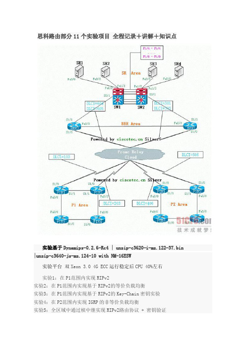
思科路由部分11个实验项目全程记录+讲解+知识点实验基于Dynamips-0.2.6-Rc4 | unzip-c3620-i-mz.122-37.bin |unzip-c3640-js-mz.124-10 with NM-16ESW实验平台双Xeon 3.0 4G ECC运行稳定后CPU 40%左右实验1:在P1范围内实现RIPv2实验2:在P1范围内实现基于RIPv2的等价负载均衡实验3:在P1范围内实现基于RIPv2的Key-Chain密钥实验实验4:在P2范围内实现IGRP的非等价负载均衡实验5:全区域中通过桢中继实现RIPv2路由协议 + 密钥验证实验6:全区域中实现EIGRP路由+FR+非等价负载均衡+验证实验7:OSPF基本配置[P1区域内配置]+DR/BDR考察实验8:单区域NBMA环境OSPF实现+验证实验9:多区域OSPF实现实验10:简单的路由重发布末节区域完全末节区域 NSSA区域 Virtual-Link 实验11:被动接口路由更新过滤策略路由路由单项重发布以及AD/Metric更改路由双向重发布P1配置部分P1R1-P1R2192.168.1.1 - 192.168.1.2 /24 P1R1上配置Lo0 200.200.200.200 /24P1R1-P1R3192.168.2.1 - 192.168.2.2 /24P1R3-P1R4192.168.3.1 - 192.168.3.2 /24P1R2-P1R4192.168.4.1 - 192.168.4.2 /24P1R1-BBR1 - 10.0.0.2 /8P1R2-BBR1 - 10.0.0.3 /8P2配置部分P2R1-P2R2172.16.1.1 - 172.16.1.2 /16 P2R1上配置Lo0 100.100.100.100 /8P2R1-P2R3172.17.1.1 - 172.17.1.2 /16P2R3-P2R4172.18.1.1 - 172.18.1.2 /16P2R2-P2R4172.19.1.1 - 172.19.1.2 /16P2R1-BBR2 - 11.0.0.2 /8P2R2-BBR2 - 11.0.0.3 /8BBR配置部分BBR1-BBR2219.146.241.1 -219.146.241.2 /24BBR1 s0/0.1 -s0/0.210.0.0.1BBR2 s0/0.1 -s0/0.211.0.0.1BBR2-SW1219.146.242.1 - 219.146.242.2BBR1-SW2219.146.243.1 - 219.146.243.2SW1-SW2219.146.244.1 - 219.146.244.2SR配置部分SR1-SW1 101.0.0.1 - 101.0.0.2 SR2-SW1 102.0.0.1 - 102.0.0.2SR3-SW2 103.0.0.1 - 103.0.0.2SR4-SW2 104.0.0.1 - 104.0.0.2SR1:lo0 105.0.0.1 Lo1 106.0.0.1SR2:lo0 107.0.0.1 Lo1 108.0.0.1实验1:在P1范围内实现RIPv2[P1R1]router ripver 2net 192.168.1.0net 192.168.2.0net 200.200.200.0[P1R2]router ripver 2net 192.168.1.0net 192.168.4.0[P1R3]router ripver 2net 192.168.2.0net 192.168.3.0[P1R4]router ripver 2net 192.168.3.0net 192.168.4.0验证结果,P1R1[Copy to clipboard]CODE:sh ip route:C 200.200.200.0/24 is directly connected, Loopback0R 192.168.4.0/24 [120/2] via 192.168.2.2, 00:00:22, FastEthernet0/0C 192.168.1.0/24 is directly connected, Serial1/1C 192.168.2.0/24 is directly connected, FastEthernet0/0R 192.168.3.0/24 [120/1] via 192.168.2.2, 00:00:22, FastEthernet0/0注意:区分RIP两个版本,配置时候必须配置相同的rip version,虽然有办法让他们协同工作,但是基本上没什么意义RIPV1分类路由,没30秒发送一次更新分组,分组中不包含子网掩码信息,不支持VLSM,默认进行边界自动路由汇总,且不可关闭,所以该路由不能支持非连续网络.不支持身份验证.使用跳数作为度量,管理距离 120.每个分组中最多只能包含25个路由信息.使用广播进行路由更新.RIPV2无类路由,发送分组中含有子网掩码信息,支持VLSM,但默认该协议开启了自动汇总功能,所以如需向不同主类网络发送子网信息,需要手工关闭自动汇总功能(no auto-summary),RIPV2只支持将路由汇总至主类网络,无法将不同主类网络汇总,所以不支持CIDR.使用多播224.0.0.9进行路由更新,只有对应的多播MAC地址能够响应分组,在MAC层就能区分是否对分组响应.支持身份验证.分类路由选择协议,当发送路由分组的接口所处子网与分组相关的子网属于同一主类网络,那么路由器在该接口可以把具体的子网发送出去.路由器假设该接口与分组子网使用相同的子网掩码.什么是连续子网:属于同一主类网络,使用相同的子网掩码就是连续的子网.否则就是非连续子网.在接口上手工汇总命令:ip summary-address rip被汇总子网被汇总子网掩码RIP使用UDP(用户报文协议)520端口传输路由更新分组RIP只能做等价负载均衡实验2 在P1范围内实现基于RIPv2的等价负载均衡P1R1上的Lo0为200.200.200.200,作为此实验的目的IP[P1R4]int f0/0no ip route-cacheint s1/0no ip route-cacheaccess-list 101 permit ip icmp any 200.200.200.0 0.0.0.255debug ip pac 101验证结果[P1R2]router ripver 2net 192.168.1.0net 192.168.4.0[P1R3]router ripver 2net 192.168.2.0net 192.168.3.0[P1R4]router ripver 2net 192.168.3.0net 192.168.4.0P1R4上sh ip route,可以看到[Copy to clipboard]CODE:Gateway of last resort is not setR 200.200.200.0/24 [120/2] via 192.168.4.1, 00:00:16, FastEthernet0/0 [120/2] via 192.168.3.1, 00:00:09, Serial1/0C 192.168.4.0/24 is directly connected, FastEthernet0/0R 192.168.1.0/24 [120/1] via 192.168.4.1, 00:00:16, FastEthernet0/0R 192.168.2.0/24 [120/1] via 192.168.3.1, 00:00:09, Serial1/0C 192.168.3.0/24 is directly connected, Serial1/0到达200.200.200.0网段的metric完全相同,并且通过两个出口P1R4#ping 200.200.200.200 re 2[Copy to clipboard]CODE:Type escape sequence to abort.Sending 2, 100-byte ICMP Echos to 200.200.200.200, timeout is 2 seconds: !!Success rate is 100 percent (2/2), round-trip min/avg/max = 12/14/16 ms P1R4#16:00:24: IP: tableid=0, s=192.168.4.2 (local), d=200.200.200.200 (FastEthernet0/0), routed via RIB16:00:24: IP: s=192.168.4.2 (local), d=200.200.200.200 (FastEthernet0/0), len 100, sending16:00:24: IP: tableid=0, s=192.168.3.2 (local), d=200.200.200.200 (Serial1/0), routed via RIB16:00:24: IP: s=192.168.3.2 (local), d=200.200.200.200 (Serial1/0), len 100, sending注意1.route-cache是进程交换, ip route-cache是快速交换, ip route-cache optimum 是最优交换, route-cache distributed是分布式最优,负载均衡需要切换为进程交换(根据分组处理,而不是目的地),7000以上系列需要no ip cef2.通过定义ACL定义过滤,然后debug抓取特定的数据包,可以最优化显示debug 结果均衡负载的知识:均衡负载可以是基于目标地址或者是基于每个packet的所谓基于目标地址的均衡负载,是说假如有2条到达目标地址的路径,那么第一个packet将通过第一条链路到达第一个目标设备,第二个packet将通过第二条链路到达第二个目标设备,第三个packet又将通过第一条链路到达第三个目标设备等等,以次类推.当Cisco路由器工作在默认的交换模式,Fast Switching(快速交换)模式下,就使用这种类型的均衡负载 Fast Switching的工作原理是:当路由器对第一个packet进行发往目标地址的处理的时候,先查看路由表和选择出口接口,然后获取组成 frame的信息(比如ARP表的查询)并进行封装,然后传输.之前获取的这些路由和数据链路信息将被保存在快速交换的cache中.接下来,当有要到达和第一个包相同的目标地址的包的时候,就可以不进行路由表和ARP表的查询,直接对packet进行交换快速交换降低了CPU的占用和处理时间,并意味着去往某个目标地址的packet 都从相同的路由器接口被路由出去.当有到达同一网络不同主机的packet,路由器可能会吧这些packet通过另外一条链路进行路由.因此,路由器能做的最好的就是给予目标地址的均衡负载。
路由器仿真软件实验报告
路由器仿真软件实验【实验目的】1)掌握路由器在网络中的作用。
2)掌握路由器的组成,路由器设备的选型。
3)掌握Cisco路由器仿真软件Boson路由仿真软件的使用。
4)通过仿真软件的使用掌握Cisco路由器的基本配置方法,熟练掌握路由器的基本配置命令,包括路由器名称设定、保护口令设定、口令封装、历史设定、接口描述、查看命令等。
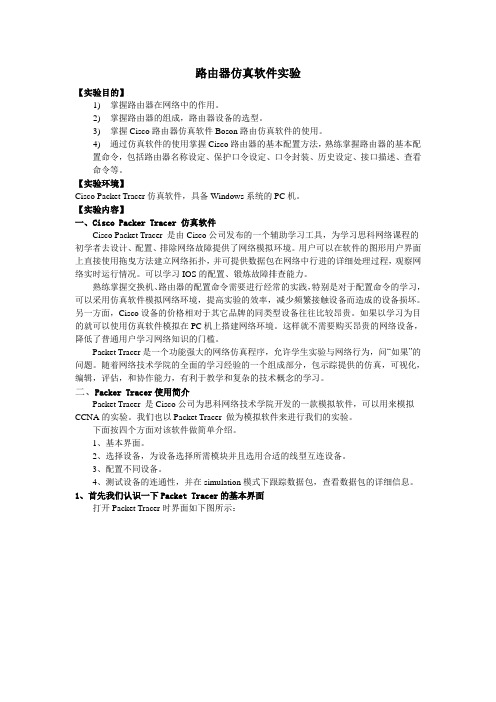
【实验环境】Cisco Packet Tracer仿真软件,具备Windows系统的PC机。
【实验内容】一、Cisco Packer Tracer 仿真软件Cisco Packet Tracer 是由Cisco公司发布的一个辅助学习工具,为学习思科网络课程的初学者去设计、配置、排除网络故障提供了网络模拟环境。
用户可以在软件的图形用户界面上直接使用拖曳方法建立网络拓扑,并可提供数据包在网络中行进的详细处理过程,观察网络实时运行情况。
可以学习IOS的配置、锻炼故障排查能力。
熟练掌握交换机、路由器的配置命令需要进行经常的实践,特别是对于配置命令的学习,可以采用仿真软件模拟网络环境,提高实验的效率,减少频繁接触设备而造成的设备损坏。
另一方面,Cisco设备的价格相对于其它品牌的同类型设备往往比较昂贵。
如果以学习为目的就可以使用仿真软件模拟在PC机上搭建网络环境。
这样就不需要购买昂贵的网络设备,降低了普通用户学习网络知识的门槛。
Packet Tracer是一个功能强大的网络仿真程序,允许学生实验与网络行为,问“如果”的问题。
随着网络技术学院的全面的学习经验的一个组成部分,包示踪提供的仿真,可视化,编辑,评估,和协作能力,有利于教学和复杂的技术概念的学习。
二、Packer Tracer使用简介Packet Tracer 是Cisco公司为思科网络技术学院开发的一款模拟软件,可以用来模拟CCNA的实验。
我们也以Packet Tracer 做为模拟软件来进行我们的实验。
下面按四个方面对该软件做简单介绍。
10、思科模拟器ACL实验
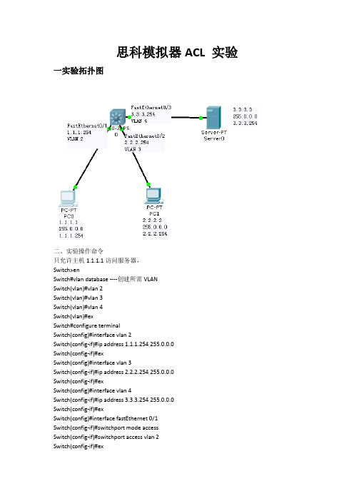
思科模拟器ACL 实验一实验拓扑图二、实验操作命令只允许主机1.1.1.1访问服务器,Switch>enSwitch#vlan database ----创建所需VLANSwitch(vlan)#vlan 2Switch(vlan)#vlan 3Switch(vlan)#vlan 4Switch(vlan)#exSwitch#configure terminalSwitch(config)#interface vlan 2Switch(config-if)#ip address 1.1.1.254 255.0.0.0Switch(config-if)#exSwitch(config)#interface vlan 3Switch(config-if)#ip address 2.2.2.254 255.0.0.0Switch(config-if)#exSwitch(config)#interface vlan 4Switch(config-if)#ip address 3.3.3.254 255.0.0.0Switch(config-if)#exSwitch(config)#interface fastEthernet 0/1Switch(config-if)#switchport mode accessSwitch(config-if)#switchport access vlan 2Switch(config-if)#exSwitch(config)#interface fastEthernet 0/2Switch(config-if)#switchport mode accessSwitch(config-if)#switchport access vlan 3Switch(config-if)#exSwitch(config)#interface fastEthernet 0/3Switch(config-if)#switchport mode accessSwitch(config-if)#switchport access vlan 4Switch(config-if)#exSwitch(config)#access-list 150 permit ip 1.1.1.1 0.0.0.0 3.3.3.3 0.0.0.0 Switch(config)#interface vlan 2Switch(config-if)#ip access-group 150 inSwitch(config-if)#exitSwitch(config)#interface vlan 3Switch(config-if)#ip access-group 150 inSwitch(config-if)#exit只允许主机1.1.1.1 telnet路由器,Switch(config)#username zte password zte Switch(config)#line console 0Switch(config-line)#password zteSwitch(config-line)#loginSwitch(config-line)#exiSwitch(config)#line console 0Switch(config-line)#access-class 1 in Switch(config-line)#exiSwitch(config)#line vty 0Switch(config-line)#password zteSwitch(config-line)#loginSwitch(config-line)#exiSwitch(config)#interface vlan 2Switch(config-if)#ip access-group 1 in Switch(config-if)#exSwitch(config)#interface vlan 2Switch(config-if)#ip access-group 1 in Switch(config-if)#exSwitch(config)#interface vlan 3Switch(config-if)#ip access-group 1 in Switch(config-if)#ex。
cisco_综合实验1
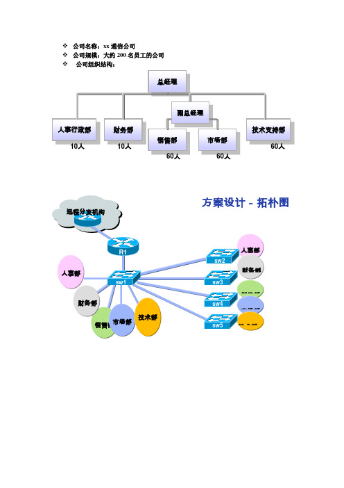
❖公司名称:xx通信公司❖公司规模:大约200名员工的公司❖公司组织结构:IP地址规划全部的地址空间是192.168.10.0/24和192.168.11.0/24。
❖远程分支机构的IP地址是192.168.20.0/24。
要求:❖交换机配置▪配置主机名▪加密保存的密码▪添加VLAN▪配置VLAN Trunk❖路由器配置▪配置主机名▪加密保存的密码▪在路由器上配置单臂路由▪在路由器上配置默认路由访问远程分支机构综合实验1SW1配置命令:1.预配sw1#config tsw1(config)#enable secret pepsisw1(config)#no ip domain-lookup no ip domain-lookup:告诉Router不要对它不知道的字符串做DNS解析,否则当你敲错命令的时候,它就会傻找。
sw1(config)#line console 0sw1(config-line)#password pepsisw1(config-line)#loginsw1(config-line)#logging synchronous logging synchronous是一个很有用的命令,它应该是一个默认的配置,但是它不是!它可以阻止那些烦人的控制台信息来打断你当前的输入,从而使输入信息显得更为简单易读。
sw1(config-line)#exec-timeout 0 0console 模式下exec-timeout 0 0 表示永不超时exec-timeout 0 10 表示登录后无操作10秒后超时登出,这时候就要重新输入密码登陆设备。
sw1(config-line)#exitsw1(config)#line vty 0 4sw1(config-line)#password pepsisw1(config-line)#loginsw1(config-line)#logging synchronoussw1(config-line)#exec-timeout 0 0sw1(config-line)#exitsw1(config)#host sw12.定义VTP模式:sw1(config)#vtp domain ciscosw1(config)#vtp mode serversw1(config)#vtp password ok3.创建VLANsw1(config)#vlan 10sw1(config-vlan)#name 10sw1(config-vlan)#exitsw1(config)#vlan 20sw1(config-vlan)#name 20sw1(config-vlan)#exitsw1(config)#vlan 30sw1(config-vlan)#name 30sw1(config-vlan)#exitsw1(config)#vlan 40sw1(config-vlan)#name 40sw1(config-vlan)#exitsw1(config)#vlan 50sw1(config-vlan)#name 50sw1(config-vlan)#exit配置f0/1到f0/5sw1(config)#interface range fastEthernet 0/1 - f0/5 sw1(config-if-range)#switchport mode trunksw1(config-if)#switchport trunk encap dot1qsw1(config-if-range)#exitSw2sw2(config)#interface fastEthernet 0/1sw2(config-if)#switchport mode trunksw2(config-if)#switchport trunk encap dot1qsw2(config-if)#endsw2(config)#vtp domain ciscosw2(config)# vtp mode clientsw2(config)#vtp password okSw3Sw3(config)#interface fastEthernet 0/1sw3(config-if)#switchport mode trunksw3(config-if)#switchport trunk encap dot1qsw3(config-if)#endsw3(config)#vtp domain ciscosw3(config)# vtp mode clientsw3(config)#vtp password okSw4Sw4(config)#interface fastEthernet 0/1Sw4(config-if)#switchport mode trunkSw4(config-if)#switchport trunk encap dot1qSw4(config-if)#endSw4(config)#vtp domain ciscoSw4config)# vtp mode clientSw4config)#vtp password okSw5Sw5(config)#interface fastEthernet 0/1Sw5(config-if)#switchport mode trunkSw5(config-if)#switchport trunk encap dot1qSw5(config-if)#endSw5(config)#vtp domain ciscoSw5(config)# vtp mode clientSw5(config)#vtp password okR1r1(config)#interface fastEthernet 0/1r1(config-if)#no shutdownr1(config-if)#no ip addressr1(config-if)#exitr1(config)#interface fastEthernet 0/1.10r1(config-subif)#encapsulation dot1Q 10r1(config-subif)#ip address 192.168.10.1 255.255.255.128 r1(config-subif)#exitr1(config)#interface fastEthernet 0/1.20r1(config-subif)#encapsulation dot1Q 20r1(config-subif)#ip address 192.168.10.129 255.255.255.128r1(config-subif)#exitr1(config)#interface fastEthernet 0/1.30r1(config-subif)#encapsulation dot1Q 30r1(config-subif)#ip address 192.168.11.1 255.255.255.128 r1(config-subif)#exitr1(config)#interface fastEthernet 0/1.40r1(config-subif)#encapsulation dot1Q 40r1(config-subif)#ip address 192.168.11.129 255.255.255.224 r1(config-subif)#exitr1(config)#interface fastEthernet 0/1.50r1(config-subif)#encapsulation dot1Q 50r1(config-subif)#ip address 192.168.11.161 255.255.255.224 r1(config-subif)#exit。
Cisco路由模拟器实验总汇
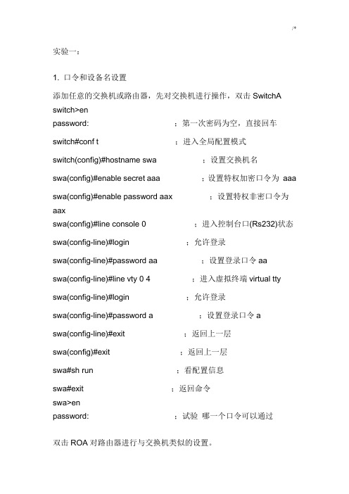
实验一:1. 口令和设备名设置添加任意的交换机或路由器,先对交换机进行操作,双击SwitchA switch>enpassword: ;第一次密码为空,直接回车switch#conf t ;进入全局配置模式switch(config)#hostname swa ;设置交换机名swa(config)#enable secret aaa ;设置特权加密口令为aaa swa(config)#enable password aax ;设置特权非密口令为aaxswa(config)#line console 0 ;进入控制台口(Rs232)状态swa(config-line)#login ;允许登录swa(config-line)#password aa ;设置登录口令aaswa(config-line)#line vty 0 4 ;进入虚拟终端virtual tty swa(config-line)#login ;允许登录swa(config-line)#password a ;设置登录口令aswa(config-line)#exit ;返回上一层swa(config)#exit ;返回上一层swa#sh run ;看配置信息swa#exit ;返回命令swa>enpassword: ;试验哪一个口令可以通过双击ROA对路由器进行与交换机类似的设置。
2. 清除口令清除交换机口令,实际中是在开机时按住交换机上的mode钮,本模拟机按Ctrl+Break清除路由器口令,参考如下:双击ROA先配置路由的特权口令:router>enpassword: ;第一次密码为空,直接回车router#conf t ;进入全局配置模式router(config)#enable secret aaa ;设置特权加密口令为aaa router(config)#exit ;返回router#exitrouter>enpassword:aaarouter#清除口令是打开寄存器配置开关:router#reload ;重新启动,按Ctrl+Break rommon>rommon>confreg 0x2142 ;跳过配置,26xx 36xx 45xx rommon>reset;重新引导,等效于重开机router>enpassword:router#conf trouter(config)#enable secret bbb ;设置特权加密口令为aaa router(config)#config-register 0x2102 ;正常使用配置文件router(config)#exitrouter#exitrouter>enpassword:bbbrouter#=============================================================================== =================实验二:计算机与交换机IP地址设置图文件:switch1规划ip地址:PCA: 10.65.1.1PCB: 10.65.1.2SWA: 10.65.1.31.双击PCA输入用户名:root输入口令:linux设置IP :[root#PCA root]# ifconfig eth0 10.65.1.1 netmask255.255.0.0查看IP :[root#PCA root]# ifconfig删除IP : [root#PCA root]# ifconfig eth0 10.65.1.1 netamsk255.255.0.0 down设置网关:[root#PCA root]# route add default gw 10.65.1.9查看网关:[root#PCA root]# route删除网关:[root#PCA root]# route del default gw 10.65.1.92.双击PCB输入用户名:root输入口令:linux设置IP :[root#PCB root]# ifconfig eth0 10.65.1.2 netmask255.255.0.0设置网关:[root#PCB root]# route add default gw 10.65.1.93.双击SWA进入特权模式: switch>en进入全局配置模式: switch#conf t进入默认VLAN状态: switch(config)#int vlan 1设置ip地址和掩码: switch(config-if)#ip address 10.65.1.3 255.255.0.0 设置switch的网关: switch(config)#ip defaule-gateway 10.65.1.9查看设置: #sh run4.回PCA[root@PCA root]# ping 10.65.1.1[root@PCA root]# ping 10.65.1.2[root@PCA root]# ping 10.65.1.35.修改PCB的ip地址修改为不同网段的一个ip地址,再从PCA Ping PCB。
Cisc0路由器模拟实验
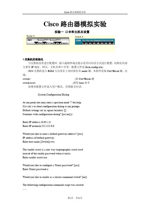
Cisco路由器模拟实验实验一口令和主机名设置1.交换机的初始化当交换机没有进行配置时,接入超级终端会提示是否以对话方式进行配置,初始化内容主要有IP地址、网关、主机名和口令等。
配置文件是flash:config.text。
2924交换机进入ROM方式是在上电时按住其mode键,本软件是按Ctrl+Break键,出现:switch> ;按Ctrl+Break键switch:reset ;或用boot命令如果有配置文件进入用户模式,否则提交对话:--- System Configuration Dialog ---At any point you may enter a question mark '?' for help.Use ctrl-c to abort configuration dialog at any prompt.Default settings are in square brackets '[]'.Continue with configuration dialog? [yes/no]:yEnter IP address:10.65.1.8Enter IP netmask:255.255.0.0Would you like to enter a default gateway address? [yes]:IP address of default gateway:Enter host name [Switch]:swaThe enable secret is a one-way cryptographic secret usedinstead of the enable password when it exists.Enter enable secret:aaaWould you like to configure a Telnet password? [yes]:Enter Telnet password:aWould you like to enable as a cluster command switch? [no]:The following configuration command script was created:......Press RETURN to get started.swa>enpassword:aaaswa#copy run start (保存配置信息)swa#dir flash: (查看闪存中的文件)再次进入对话方式:swa#setup2.路由器的初始化路由器初始化与交换机类似,上电时按Ctrl+Break,进入ROM监控状态router> ;用户模式,按Ctrl+Break rommon>reset ;进入ROM监控状态,复位引导(没有配置文件或采用寄存器设置跳过配置文件提示对话信息)Continue with configuration dialog? [yes/no]:yesAt any point you may enter a question mark '?' for help.Use ctrl-c to abort configuration dialog at any prompt.Default settings are in square brackets '[ ]'.Basic management setup configures only enough connectivityfor management of the system,extended setup will ask youto configure each interface on the systemWould you like to enter basic management setup? [yes/no]:yesConfiguring global parameters:Enter host name [router]:ra回车The enable secret is a password used to protect access toprivileged EXEC and configuration modes. This password,after entered,becomes encrypted in the configuration.Enter enable secret:aaa回车The enable password is used when you do not specify anenable secret password,with some older software versions,and some boot images.Enter enable password:aa回车The virtual terminal password is used to protectaccess to the router over a network interface.Enter virtual terminal password :a回车Enter interface name used to connect to the managementnetwork from the above interface summary:FastEthernet0/0回车Configuring interface FastEthernet0/0:回车Use the 100 Base-TX (RJ-45) connector? [yes]:回车Operate in full-duplex mode? [no]:回车Configure IP on this interface? [yes]:回车IP address for this interface [ ]:10.1.1.1回车Subnet mask for this interface [ ]:255.0.0.0回车[0] Go to the IOS command prompt without saving this config.[1] Return back to the setup without saving this config.[2] Save this configuration to nvram and exit.Enter your selection [2]:回车ra>enpassword aaa (进入特权模式)ra#show run (显示配置信息)ra#w (保存配置信息)ra#dir flash: (显示配置文件)(配置文件在2621路由器不能删除,放弁配置文件要用寄存器设置0x2142);3. 用命令行设置交换机和路由器的口令和主机名交换机和路由器的口令和主机名的设置基本相同,在提问对话时,回答n,则进入命令行的状态。
实验一:Cisco模拟器静态路由实验

• 3、连线的时候注意,PC——交换机用直通线,交换机——路由器用直通 线,路由器——路由器用交叉线。
• 配置完毕后,首先测试PC能否连接各自网关
• 我们从左到右依次配置测试各设备 • 用PC1ping路由器A的fa1/0端口,看是否能ping通?
实验一:Cisco模拟器静态 路由实验
通过实现两台PC互联实验掌握路由的用法和原理
实验条件
• Cisco模拟器6.0(仿真实验)
一、组网:请按照下面图例组网并配置好端口的IP地址,并连线。
• 注意事项:
• 1、可以在路由器和PC间用交换机连接,因为在真实环境里,PC网卡速率 往往和路由器不匹配,无法直连,所以我们可以用交换机做一个中转(交 换机的端口一般都是自适应的,上可连路由器,下可连PC)。
上配置静态路由
• 继续验证,发现通了。
• 为什么通了?因为数据包到达C了,并且在上一个步骤,C已经通过静态路由知道要回复 192.168.1.101应该们先不做验证,我们自己推导一下: • 数据包能否到达D的fa0/0?当然可以,因为数据包能够到达C的fa1/0,并且D的fa0/0和C的fa1/0处于同一个
• 告诉ABCD,剩下两个网段11.0.0.0 10.0.0.0在哪里 • 因为D有11.0.0.0网段接口,并且刚才也配置了,所以不用配了 •A •B •C •D • 告诉E,192.168.1.0在哪里
• 可以看到,PC1能连接E的两个端口了
• 最后,可以看到PC1成功连通PC2
• 我们可以看看路由器的路由表,以C为例
• 可以看到,我们没做任何配置,PC可以连通和它不同网段的接口,为什么? • 因为,192.168.2.1和192.168.1.1在同一个路由器上,它们是同一个路由器的
- 1、下载文档前请自行甄别文档内容的完整性,平台不提供额外的编辑、内容补充、找答案等附加服务。
- 2、"仅部分预览"的文档,不可在线预览部分如存在完整性等问题,可反馈申请退款(可完整预览的文档不适用该条件!)。
- 3、如文档侵犯您的权益,请联系客服反馈,我们会尽快为您处理(人工客服工作时间:9:00-18:30)。
(不通:
不是一个网段,且不在一个VLAN)[root@PCA root]# ping 10.66.1.1
从PCB到PCD测试:
(不通:
要求trunk)
[root@PCB root]# ping 10.66.1.3
从PCA到SWA测试:
(通)
[root@PCA root]# ping 10ch2
规划ip地址
PCA的ip地址:
10.65.1.1
PCB的ip地址:
10.66.1.1
PCC的ip地址:
10.65.1.3
PCD的ip地址:
10.66.1.3
SWA的ip地址:
10.65.1.7
SWB的ip地址:
10.65.1.8
SWA的为trunk
SWB的为trunk
实验五路由器接口ip设置
装入图文件:
router1d
本实验两个计算机,一个路由器,测试路由器的直路由。
设置PCA的IP地址为:10.65.1.1 255.255.0.0
设置PCB的IP地址为:10.66.1.1 255.255.0.0
设置的IP为:10.65.1.2 255.255.0.0
设置的IP为:10.66.1.2 255.255.0.0
router#exit
router>en
password:
aaa
router#
清除口令是打开寄存器配置开关:
router#reload;重新启动,按Ctrl+Break rommon>
rommon>confreg 0x2142;跳过配置,26xx 36xx 45xxrommon>reset;重新引导,等效于重开机router>en
flash file name:
C2621.bin
###############################################################
###############################################################
SWA(config-if)#switchport access vlan 2
SWA(config-if)#switchport access vlan 2
SWA(config-if)# Ctrl+z
SWA#sh vlan
与SWA类似设置SWB的VLAN。
3.测试可通性
从PCA到PCC测试:
(通)
[root@PCA root]# ping 10.65.1.3
roa(config-if)#ip address 10.66.1.2 255.255.0.0
roa(config-if)#no shut
roa(config-if)#clock rate 64000
roa(config-if)#ip address 10.67.1.2 255.255.0.0
#######
ok!
router#dir flash:
c2621.bin
这种方式传输的速度较快,使用的是以太网的速率。但要求IOS是好的,所以升级
IOS使用这种方式较好。
3.在rommon监控状态下,使用TFTP升级
装入图文件:
router1c
要求路由器console与计算机rs232相连,路由器与计算机网卡相连。
实验四:
路由器的升级
1.在ROM监控模式下,使用console通过计算机的超级终端设置。
装入图文件:
router1a
要求路由器的console与计算机的rs232相连。
router>Ctrl+Break;进入ROM监控状态
rommon>copy xmodem:
c2621.bin flash:
c2621.bin;从console升级IOS
ok!
rommon>dir flash:
c2621.bin
这种方式传送的速度比较慢,使用的是RS232串行接口的速率,波特率一般为9600,
但不需要IOS的支持,在IOS损坏的情况下往往使用这种方式。
2.在特权模式下的升级
装入图文件:
router1b
要求TFTP Server (PCA)接入路由器的以太口,且PCA的ip地址与路由接口的ip地址
password:
router#conf t
router(config)#enable secret bbb;设置特权加密口令为aaa router(config)#config-register 0x2102;正常使用配置文件router(config)#exit
router#exit
router>en
从PCA到SWB测试:
(通)
[root@PCA root]# ping 10.65.1.8
从SWA到PCA测试:
(通)
SWA#ping 10.65.1.1
从SWA到SWB测试:
(通)
SWB#ping 10.65.1.8
再将连接两个交换机的接口设置成trunk。
SWA(config-if)#switchport mode trunk
swa(config-line)#password a;设置登录口令a
swa(config-line)#exit;返回上一层
swa(config)#exit;返回上一层
swa#sh run;看配置信息
swa#exit;返回命令
swa>en
password:
;试验哪一个口令可以通过双击ROA对路由器进行与交换机类似的设置。2.清除口令
2.设置VLAN
双击SWA:
改名Switch为SWA,建立2个vlan:
2 3
SWA#vlan database
SWA(vlan)#vlan 2
SWA(vlan)#vlan 3
SWA(vlan)#exit
SWA#conf t
SWA#sh vlan
将加入到vlan 2
SWA(config-if)#switchport access vlan 2
5.修改PCB的ip地址
修改为不同网段的一个ip地址,再从PCA Ping PCB。
修改为相同网段的一个ip地址,再从PCA Ping PCB。
断开交换机与PCB计算机连线,再从PCA Ping PCB。
[root@PCA root]# ping 10.65.1.2
================================================================================================
3.双击SWA
进入特权模式:
switch>en
进入全局配置模式:
switch#conf t
进入默认VLAN状态:
switch(config)#int vlan 1
设置ip地址和掩码:
switch(config-if)#ip address 10.65.1.3 255.255.0.0设置switch的网关:
在一个网络段。设置TFTP的ip地址为:10.65.1.1
双击HostA:
login:
root
password:
linux
双击要升级的路由器:
设置与之tftp server相联接口的ip地址
router#copy tftp flash:
tftp server ip address:10.65.1.1
1.设置计算机ip地址
设置IP:
255.255.0.0
查看IP:
[root#PCA root]# ifconfig
设置网关:
[root#PCA root]# route add default gw 10.65.1.2
查看网关:
[root#PCA root]# route
设置IP:
255.255.0.0
PCA:
10.65.1.1
PCB:
10.65.1.2
SWA:
10.65.1.3
1.双击PCA
输入用户名:
root
输入口令:
linux
设置IP:
255.255.0.0
查看IP:
[root#PCA root]# ifconfig
删除IP :
255.255.0.0 down
设置网关:
[root#PCA root]# route add default gw 10.65.1.9
swa(config)#line console 0;进入控制台口(Rs232)状态swa(config-line)#login;允许登录
swa(config-line)#password aa;设置登录口令aa swa(config-line)#line vty 0 4;进入虚拟终端virtual tty swa(config-line)#login;允许登录
password:
bbb
router#
================================================================================================
实验二:
计算机与交换机IP地址设置
图文件:
switch1
规划ip地址:
查看IP:
[root#PCB root]# ifconfig
2.双击ROA,配置路由器的接口IP地址:
router>en
router#conf t
router(config)#hostname roa