FDS模拟火灾的实验研究
FDS模拟火灾的实验研究

科学技术2010.7 75FDS 模拟火灾的实验研究于慧鸣鞍山市消防支队 辽宁 鞍山 114000【摘 要】本文使用FDS 火灾模型模拟火灾,分析建筑内发生火灾时,可燃物的数量对于烟气层高度、温度和能见距离的影响情况,得出危险指标与各影响因素之间的关系。
【关键词】烟气层高度 能见距离 FDS 火灾模型一、绪论由于当烟气层高于人眼特征高度(人眼的特征高度通常为1.3~1.8 m,我们取1.5 m),烟气层温度达到180 ℃时,则其产生的热辐射就会对人体造成不可恢复的烧伤;当烟气层高度低于人眼特征高度,烟气层温度达到115 ℃时,就会对人体构成危险。
本文使用FDS 火灾模型模拟火灾,分析建筑内发生火灾时,可燃物的种类和数量等因素对于烟气层高度、温度和能见距离的影响,得出危险指标与各影响因素之间的关系。
二、利用FDS 模拟火灾1、FDS 火灾模型简介FDS 火灾模型包括两大部分。
第一部分简称FDS4,是求解微分方程的主程序,需要用户创建文本来描述火灾场景;第二部分称SMOKEVIEW,可以直观的查看计算结果。
FDS 的输入文件分成三部分:第一部分为几何参数和网格的设置;第二部分为有关燃烧过程的设置,如燃烧时间、火源功率、通风口的设置等;第三部分为输出数据的设置,如某点或某个面上的温度、密度、混合组分在火灾过程中随时间的变化情况等。
2、FDS 模拟火灾 (1)参数设定为了准确地求解火灾的相关问题,设置基本参数如下:①设置烟的减光系数与能见距离之积C=1(系统默认值为3)。
对于发光物质来说C=8,对于反光物质来说C=3,但在性能化评估中为保守起见通常取C=1,因此,本文取C=1。
②室内温度为20 ℃;(2)火灾模拟图2.1 模拟火灾基本模型如图2.1所示模拟火灾的基本模型,建立两间尺寸均为4.0 m×4.0 m×4.0 m 房间,本文以房间1作为分析对象,设置床为火源且热释放速率稳定。
基于FDS模拟温度场作用下钢框架性能化抗火研究3篇
基于FDS模拟温度场作用下钢框架性能化抗火研究3篇基于FDS模拟温度场作用下钢框架性能化抗火研究1基于FDS模拟温度场作用下钢框架性能化抗火研究随着现代建筑结构的迅速发展和建筑的高度增加,火灾对建筑结构的破坏性越来越大,而钢框架结构具有较高的强度、刚度和稳定性,成为高层建筑的主要结构形式。
然而,在火灾环境下,钢框架的抗火性能成为建筑安全的关键因素之一。
因此,本研究基于FDS模拟温度场作用下钢框架性能化抗火研究,探索钢框架在火灾环境下的稳定性和热力学性能。
首先,本研究通过FDS软件模拟了钢框架在火灾环境下的温度场,并计算了钢结构的温度分布。
通过对温度场的分析,本研究发现,在火焰接触面和火场上方,温度分布较高,而在下部温度分布较低。
接着,本研究通过对钢框架的力学性能和热学性能计算,探索了钢框架在火灾环境下的稳定性。
采用ABAQUS有限元模拟软件对钢框架结构进行建模,模拟钢构件受火灾温度影响的力学性能变化。
研究发现,在火焰较强的区域,钢构件的强度和刚度逐渐降低,随着火焰的接触,钢构件的强度也逐渐减少。
最后,本研究面向钢框架的抗火性能提出了一些对策和建议,包括增加钢材的保温层和表面防火涂层,优化钢框架的结构设计,提高钢构件的抗火性能等。
这些对策和建议可以显著提高钢框架的抗火能力,从而保障高层建筑在火灾发生时的安全。
总之,本研究通过FDS模拟温度场作用下钢框架性能化抗火研究,深入探索了钢框架在火灾环境下的稳定性和热力学性能。
本研究为钢框架的抗火设计提供了理论和技术支持,对于保障高层建筑的安全发挥了重要的作用本研究通过FDS模拟和有限元计算,深入探索了钢框架在火灾环境下的稳定性和热力学性能。
针对钢框架存在的抗火问题,提出了增加保温层、表面防火涂层以及优化结构设计等建议。
这些建议可以显著提高钢框架的抗火能力,为高层建筑的安全保障提供了理论和技术支持。
本研究成果对于促进建筑结构安全和防火设计发挥了重要作用基于FDS模拟温度场作用下钢框架性能化抗火研究2基于FDS模拟温度场作用下钢框架性能化抗火研究随着经济的发展,建筑行业各种新型建筑材料种类繁多,其中钢结构得到了广泛的应用。
基于fds灭火模型的消防模拟训练系统研究

测温热电偶
消防水枪消防水枪
燃
烧
喷
嘴
燃烧喷嘴
200400600800
1 0000
204060
灭火时间/s
60°30°
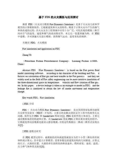
90°120°150°不同水枪喷射角下热释放速率随时间的变化曲线
3)可以看出,在该火灾场景下,当火源的固定热释放速率大于有效消防水的吸热速率,燃气不断供应并被但由于受到水流冲击,火焰并不稳定,火源的热释放速率将在一个区间内波动;而当火源的固定热释放速率小于有效消防水的吸热速率,维持燃烧反应的热量逐渐减又由于水柱持续压迫火焰表面,使着火源与氧气的接触面积减少,导致火焰逐渐熄灭,热释放速率最终变为零。
可知,该场景下水枪喷射角与火源扑灭时间近似呈线性关系,即消防水枪的喷射角越大,扑灭火焰的时主要是在水流量一致的情况下,较大的水枪喷射角可使水雾的覆盖面积更大,降温效果更好,同时更好地
0100200300400500600700800
0-10
2010
40
3070
6050灭火时间/s
60°30°90°120°150°
火源附近测点温度值/℃。
基于FDS的细水雾灭食用油火及综合体火灾数值模拟研究

基于FDS的细水雾灭食用油火及综合体火灾数值模拟研究基于FDS的细水雾灭食用油火及综合体火灾数值模拟研究引言近年来,随着人们对食品安全的关注不断提高,食用油在人们的日常生活中扮演着重要的角色。
然而,由于油具火源误操作、电器故障以及其他人为或自然因素的错误使用导致的火灾事件仍然很常见。
这些火灾不仅给人们的生命财产安全造成威胁,更容易扩散为综合体火灾,导致巨大的经济损失和环境破坏。
因此,研究食用油火灾的灭火方法具有重要意义。
本文旨在通过数值模拟研究,评估FDS(火灾动力学模拟软件)在细水雾灭食用油火及综合体火灾中的应用效果,并探讨其在实际应用中的可行性和局限性。
方法首先,我们搜集了食用油火灾的相关实验数据,包括火源特性、燃烧产物和火势的相关参数。
然后,我们使用FDS软件对食用油火灾进行了数值模拟。
在模拟中,我们考虑了油锅与周围环境的传热传质过程,并结合实验数据进行模型的参数校正。
接下来,我们引入了细水雾灭火装置,对火源进行了灭火模拟。
细水雾灭火装置通过产生微小的水雾颗粒,将其喷洒到火源区域,从而降低火源温度,阻止燃烧链反应的发生。
我们调整了灭火装置的喷雾参数,如喷雾流量、喷雾角度和喷雾粒径,以寻找最佳的灭火效果。
结果与讨论通过数值模拟,我们观察到细水雾灭火装置对食用油火灾的灭火效果。
结果显示,当灭火装置的喷雾流量适中、喷雾角度合适、喷雾粒径足够小的情况下,灭火效果较好。
细水雾能够迅速降低火源温度,减少热辐射和燃烧产物的生成,有效防止火势蔓延和扩大。
然而,我们也发现细水雾灭食用油火灾的效果与多种因素有关。
例如,火源特性、环境温度和湿度、细水雾灭火装置的位置和数量等。
因此,在实际应用中,需要根据具体情况调整灭火装置的参数和布局,以达到最佳灭火效果。
结论本研究使用了FDS软件对细水雾灭食用油火及综合体火灾进行了数值模拟研究。
通过模拟结果,我们发现细水雾灭火装置对食用油火灾具有较好的灭火效果。
然而,这一效果受到多种因素的影响,需要结合具体情况进行参数调整和装置布局。
基于FDS的核电站主储油罐间火灾数值模拟研究的开题报告

基于FDS的核电站主储油罐间火灾数值模拟研究的开题报告一、选题背景核电站是一类非常重要的基础设施,主储油罐是其重要的储油设备之一。
一旦主储油罐发生火灾,不仅会造成人员伤亡和财产损失,还会影响核电站的正常运行和稳定性。
因此,深入研究主储油罐间火灾的发生机制、演变规律和灭火方法是必要的。
通过数值模拟的方法可以对主储油罐间火灾进行研究,这种方法不仅能够缩短试验周期,还能够控制试验条件,能够得到更精确的结果。
目前,CFD软件在消防领域得到了广泛应用,但是还缺少针对主储油罐间火灾的数值模拟研究。
二、研究内容本文拟采用FDS软件进行主储油罐间火灾的数值模拟研究,主要包括以下内容:1. 建立主储油罐间火灾数值模型;2. 对火灾的发生机理、演化规律和影响因素进行分析;3. 研究水雾灭火的效果和适用范围;4. 探究其他灭火剂的可行性;5. 验证数值模拟结果的准确性和可靠性。
三、研究方法本文采用数值模拟方法进行研究,主要采用FDS软件进行模拟。
具体方法如下:1. 建立主储油罐间火灾的数值模型,包括火源、储油罐、管道和泵等设备;2. 设置模拟参数,包括火源参数、气体温度、密度等参数;3. 根据模拟结果,分析主储油罐间火灾发生的机理和演化规律;4. 研究不同灭火剂的效果和适用范围,包括水雾、露点水、惰性气体等;5. 验证数值模拟结果的准确性和可靠性。
四、研究意义本文的研究意义在于:1. 提供主储油罐间火灾灭火方案的理论基础;2. 为消防部门提供事故预测和风险评估工具;3. 优化消防设备的配置和消防方案的制定;4. 为提高核电站安全性能提供参考依据。
五、研究难点本文研究的难点在于:1. 模型参数的选择与确定,包括火源参数和储油罐等设备的参数;2. 灭火剂的选择与适用范围的研究,包括水雾、露点水、惰性气体等;3. 数值模拟结果的验证和准确性的保证。
六、进度计划本文的进度计划如下:1. 2021年11月:完成研究背景和意义的阐述,确定研究内容和范围;2. 2022年1月:完成数值模拟软件的学习和熟练使用;3. 2022年3月:建立主储油罐间火灾数值模型,进行初始模拟;4. 2022年5月:研究主储油罐间火灾的发生机理和演化规律,探究不同灭火剂的效果和适用范围;5. 2022年7月:完成数值模拟结果的验证和准确性的保证;6. 2022年9月:完成论文撰写和答辩准备工作。
基于FDS的一起亡人火灾调查及场景重构
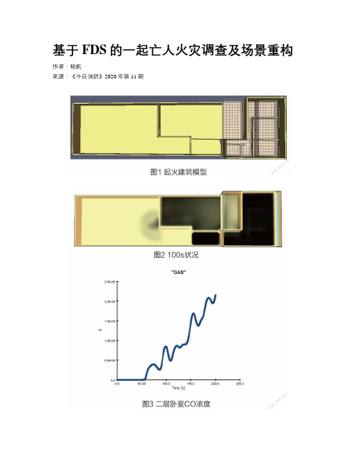
基于FDS的一起亡人火灾调查及场景重构作者:***来源:《今日消防》2020年第11期摘要:火灾场景重构对火灾事故调查人员认识火灾的发生、发展、蔓延过程具有重要意义,FDS软件是火灾场景重构最常用的软件。
本文结合一起亡人火灾事故的调查勘验过程,选取相关参数对该火场进行数值模拟,并对模拟结果进行分析,从而进一步验证了前期火灾事故调查认定的准确性。
关键词:汽车;电气火灾;危险性;实验1 火灾基本情况及调查认定安徽省某市发生一起自建房火灾,火灾造成母女2人死亡。
该自建房共三层,其中一层为家具店门面及展厅,建筑面积400平方米;二层为三间卧室,建筑面积70平方米;三层为阁楼,建筑面积70平方米。
起火时间为凌晨,建筑内共有4人,均分布在二层卧室,其中2人通过一层门面卷闸门逃生,2人未逃出在二层死亡。
1.2起火时间的认定(1)根据当事人自述,在夜里12点多在二层卧室闻到焦糊味,随后下楼查看,发现一层西侧开间内着火,自行扑救无法扑灭后报警。
(2)根据大队接警记录,大队的接警时间为0时26分。
(3)根据调取该起火建筑公路对面的监控录像,夜间0时9分05秒,该建筑一层卷帘门上方空隙处出现火光并逐渐变亮,0时16分火势变大并从卷帘门向外突破。
(4)根據调取电信部门的网络记录,位于该建筑一层的网络和电话的断线时间为0时16分42秒。
通过以上证据,结合火灾的发生发展蔓延规律,综合认定起火时间为夜间0时许。
1.3起火部位的认定(1)根据当事人自述,最先开始只在一层西侧开间发现火苗,其余部位尚未着火。
(2)建筑一层物品均已烧毁,二、三层部分物品受高温熔融。
建筑一层店面自西向东分为三个开间,中间开间堆放有大量家具板材,东侧开间堆放有床垫,西侧开间与中间开间用木板分隔。
(3)对比东侧开间与中间开间南侧立柱附近的铝合金门框,其中西侧烧损程度重于东侧,残留的门框东高西低。
(4)西侧开间与中间开间隔墙完全烧毁,仅靠近地面处有少量残留,隔墙表面的石膏板向西侧地面倒塌。
基于fds的高层建筑火灾数值模拟问题探讨
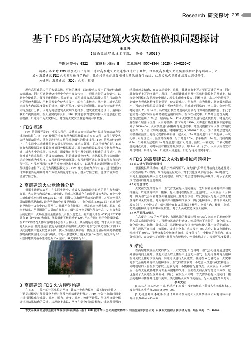
Research 研究探讨299基于FDS 的高层建筑火灾数值模拟问题探讨王亚升(陕西交通职业技术学院, 西安 710018)中图分类号:G322 文献标识码:B 文章编号1007-6344(2020)01-0299-01摘要:本文对FDS 模型进行了分析,并对高层建筑火灾危害性进行了分析,以此使高层建筑火灾模型模拟对象得到确认,之后对高层建筑FDS 火灾模型进行了构建,最后对高层建筑各项模拟结果进行了叙述,以期为现代高层建筑防火提供借鉴。
关键词:高层建筑;FDS ;火灾;模型现代高层建筑应用了大量易燃、可燃的材料,以此使火灾发生的可能性出现大幅增加,同时可燃物燃烧过程中会产生毒害气体,并释放大量的火灾烟气,以此也会使建筑内部可见度降低[1]。
综合而言,高层建筑火场高温使人员在行动能力上受到较大限制,不利因素集合使火灾发生中的伤亡率极大。
基于此,对于高层建筑火灾内部温度分布的规律、烟气可见度、烟气蔓延规律、毒害气体浓度等火灾特点进行分析,以此为高层建筑火灾烟气防排烟、建筑疏散通道设计、消防扑救工作提供基础。
在大量实践中表明,FDS 软件能够对建筑结构火灾场景进行数值模拟,以此可作为火灾特点、建筑防火灾安全性能等的评价数据。
1 FDS 概述FDS 是美国开发的一项模拟程序,是将火灾流体运动为对象进行流动动力学计算的软件[2]。
这一软件使用的求解方程为低马赫数流动N-S 方程,方程主要受火灾浮力驱动影响,重点是进行火灾热传递及烟气的传递过程。
FDS 是开放性的程序,在实践中其准确性得到大量实证检验,在火灾领域中的应用极为广泛。
FDS 拥有大涡模拟及直接数值模拟两种模拟模式,其中的数值是以湍流控制方程为基础,对火灾中的流场、浓度场、温度场时间尺寸及空间尺寸精确的进行描述。
数值模拟方法在结果上是极为精确的,但是计算量也较大。
大涡模拟是将湍流瞬时运动分解成为小尺度、大尺度两种运动部分,大尺度则可通过微分方程来直接进行计算,小尺度可通过亚格子模型建设来实现模拟,以此使计算量得到极大简化。
厨房火灾数值模拟及分析

6书柜:
依次点击Model→New Obstruction→Geometry,输入数据:
&SLCF QUANTITY='TEMPERATURE', VECTOR=.TRUE., PBX=2.50/
&SLCF QUANTITY='carbon dioxide', VECTOR=.TRUE., PBZ=1.70/
(已经由实验指导老师完成)
4.4建立实体(利用pyrosim2010):
凳子(见图1)制作步骤:(尺寸是随便输的,与实验的数据可能不一样)
&SURF ID='burner',
COLOR='RED',
HRRPUA=3.0000000E003/
4.3.3.3温度探测器布置
(注:XYZ后的数据分别表示XYZ轴三个方向上参照坐标原点的坐标)
&DEVC ID='HD 1', PROP_ID='Default', XYZ=2.50,3.50,1.70, LATCH=.FALSE./4.3.4温度和二氧化碳“切片”布置
4.2.3基本材料参数的设置
4.2.3.1地毯材料参数设置,
&MATL ID='CARPET_MATL',
SPECIFIC_HEAT=9.00,
CONDUCTIVITY=0.1600,
DENSITY=750.00,
HEAT_OF_COMBUSTION=2.2300000E004,
N_REACTIONS=1,
HEAT_OF_REACTION=2.0000000E003,
基于FDS的宿舍火灾模拟

基于FDS的宿舍火灾模拟分析1.宿舍物理参数及模型设计1.1宿舍尺寸宿舍尺寸为5m*4m*3m.宿舍内的可燃物为木头材质的床和椅子火源热释放功率为1500kw/㎡.1.2网格划分网格大小为X:40 Y:60 Z:30. 最小网格尺寸为0.1m*0.1m*0.1m 网格数为720002.模拟控制方案模拟时间为45秒,传感器建在门口高1.8米处,向下每0.4米设置一个传感器,有烟感和温感探测器。
3.模拟结果分析3.1温度分析表4.温度-时间曲线图1.温度图2.温度分析:由表4和两张温度温度图可以看出,在着火后的7秒时,室内探测点1的温度就能达到80°左右,这时已经超出人的课承受范围,在16秒的时间是,室内的温度快速的上升,在25秒时,室内的平均温度已经达到了60°。
也就是说在火灾发生的16秒内,人逃离房间受到火焰辐射热度的伤害是很小的。
25秒后,火势已经到了不可控制的程度,室内温度很高,由图2局部的温度可达到100°以上,这时人将会有生命危险。
因此,在室内发生火灾时,上方的温度会升高的很快,人在撤离货疏散时应匍匐行进。
3.2烟气浓度分析表5.烟气浓度-时间曲线图3.烟气浓度图4.烟气浓度分析:由表5的烟气浓度-时间曲线看出,从开始着火8秒的时间内,室内的烟气浓度几乎没有变化,但从9秒开始,室内的烟感探头1和2探测的烟气的浓度就开始快速的上升,到了20秒时,距地面1.8m到1.4m 的地方,烟气的浓度就有30%,这时的空气中的氧气就很少了,人的呼吸就受到了很大的影响,很多的室内火灾中人员的伤亡,大多数都是吸入了大量的烟气导致的中毒或者是窒息死亡的。
到了25秒之后,室内的烟气浓度达到了60%以上,此时室内的人员生还的可能性很低了。
而到了火灾后的29秒时,室内充满了烟气,人员无法逃生。
因此,我们可以清楚的看到,在火灾发生的16秒左右的时间,我们应弄湿毛巾,掩住口鼻,匍匐行进,避免吸入烟气,人员逃生存活的可能性还是很大的。
基于FDS的室内火灾模拟研究
基于FDS的室内火灾模拟研究目录基于FDS的室内火灾模拟研究 ........................................ 错误!未定义书签。
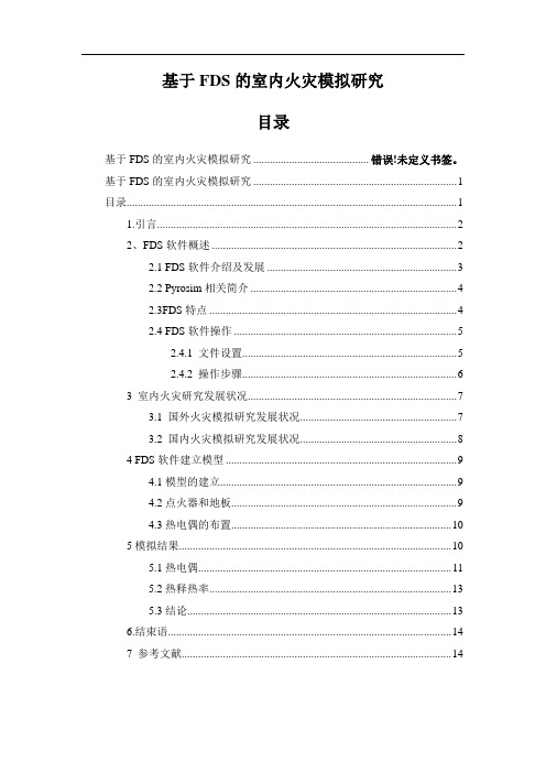
基于FDS的室内火灾模拟研究 .. (1)目录 (1)1.引言 (2)2、FDS软件概述 (2)2.1 FDS软件介绍及发展 (3)2.2 Pyrosim相关简介 (4)2.3FDS特点 (4)2.4 FDS软件操作 (5)2.4.1 文件设置 (5)2.4.2 操作步骤 (6)3 室内火灾研究发展状况 (7)3.1 国外火灾模拟研究发展状况 (7)3.2 国内火灾模拟研究发展状况 (8)4 FDS软件建立模型 (9)4.1模型的建立 (9)4.2点火器和地板 (9)4.3热电偶的布置 (10)5模拟结果 (10)5.1热电偶 (11)5.2热释热率 (13)5.3结论 (13)6.结束语 (14)7 参考文献 (14)摘要:室内装饰材料在建筑物中得到越来越广泛的运用,大多数室内装饰材料都是可燃甚至易燃材料,从而使其成为潜在火源并增加了建筑物的火灾荷载。
基于大涡模拟理论的FDS模型模拟了室内火灾中的温度和热释放率,结果证明运用FDS软件模拟室内火灾是可行的。
关键词:室内火灾FDS 火灾模拟1.引言室内火灾是指烧损室内可燃物的现象。
室内火灾如果得不到好的控制就有可能发展到某些防火分区或整个建筑火灾,随着人们生活水平的提高,各式各样的室内装饰材料如雨后春笋般出现。
建筑装饰材料因其美观的效果在建筑物中得到了越来越广泛的应用。
通过分析火灾过程中的重要参数,如热释放速率和室内温度,证明了用FDS对室内建筑装修材料的火灾特性的研究是很可靠的[1]。
2、FDS软件概述近年来,受益于计算机技术的飞速发展,火灾数值模拟技术也在其原有的基础上得到了进一步提升。
火灾本身是一个非常复杂的过程,根据所模拟的现象、研究层次和研究方法的区别,当前应用于火灾研究方面的数值模型主要有专家系统(Expert System)、区域模型(Zone Model)、场模型(Field Model)、网络模型(Network Model)和混合模型(Hybrid Model)L29[2]。
基于FDS的沙发火灾数值模拟.
基于FDS的沙发火灾数值模拟0 引言随着生活条件的提高 ,装饰家具越来越多地出现在现代建筑中 ,其种类和性能也越来越复杂.室内火灾的扩大常常与可燃的装饰家具有关.导致人员死亡的火灾中有 1 /3 是装饰家具火灾[1]。
统计结果表明,火灾中8 5%以上的死亡者是由于烟气的影响,其中大部分是吸人了烟尘及有毒气体昏迷后而致死的[2]。
本文将以典型的sofa-Fire 算例为重点,通过全尺寸实验和数值模拟相结合的方法研究其燃烧过程的热释放速率、室内温度场分布及烟气流动,为建筑火灾防治和火灾安全设计提供参考依据。
1 FDS 简介美国火灾研究机构也对本国的装饰家具的火灾特性进行了研究[3]。
最终由NIST 开发的一种模拟程序FDS,它用数值求解方法求解一组描述热驱动的低速流动的Navier-Stokes 方程,重点计算火灾中的烟气流动和热传递过程。
FDS 提供了两种数值模拟方法,即直接数值模拟(DNS:Direct Numerical Simulation)和大涡模拟(LES:Large Eddy Simulation)。
直接数值模拟是通过直接求解湍流的控制方程,对流场、温度场及浓度场的所有时间尺度和空间尺度进行精确描述,但是目前的计算条件下,只能用于对层流及较低雷诺数湍流流动的求解[4]。
一般情况下,在利用FDS 进行火灾模拟时均选用大涡模拟。
它是把包括脉动在内的湍流瞬时运动通过某种滤波方法分解成大尺度量通过数值求解微分方程直接计算出来,小尺度运动对大尺度运动的影响通过建立亚格子模型来模拟。
FDS火灾动态模拟软件主要由两部分组成,分别是FDS和Smokeview部分。
其中,FDS部分主要是用来完成对火灾场的创建和计算阶段。
而Smokeview 部分则是对FDS计算结果的可视化,它以三维动态的形式显示火灾发生的全过程。
2 couch 场景布置场景长2.4 米,宽1.0 米,高2.4 米。
在X 轴方向上共设有24 个网格,Y 轴方向上设有10 个网格。
基于FDS的火灾模拟与应用探讨
基于FDS的火灾模拟与应用探讨摘要FDS(火灾动力模拟Fire Dynamics Simulator)是基于火灾动力流体学模型的计算模拟软件,它根据建筑和火灾的特性,侧重于计算火灾中产生的烟气和热传递的过程,在火灾安全工程领域中应用十分广泛,可较直观的模拟三维空间内空气的温度、速度和烟气的流动情况等。
本文以一装置泄漏为例,在FDS 中建模,并对泄漏火灾进行模拟,获得烟气运动、温度变化的规律。
关键词FDS;火灾模拟Fire simulation and application on FDSZhang Ye(Petrochina Fushun Petrochemical Company,Liaoning Fushun 113008,China)Abstract FDS (Fire Dynamics Simulator)is based on the Fire power fluid model simulating software,according to the character of the building and Fire,it focuses on calculation of flue gas and heat transfer in the Fire process,and they are widely used in the field of Fire safety engineering can be more intuitive simulation of the three-dimensional space air temperature,velocity and flow situation of flue gas,etc. In this paper,a device leakage is taken as an example to model in FDS,and the leakage fire is simulated to obtain the law of smoke movement and temperature change.Key words FDS;Fire simulation1 FDS介绍FDS(火灾动力模拟Fire Dynamics Simulator)是由美国国家标准局建筑火灾研究实验室(NIST)开发的,主要目的是解决消防安全工程中的典型火灾问题,软件包含FDS 和Smokeview两部分[1]。
基于FDS的室内火灾蔓延特性研究
基于FDS的室内火灾蔓延特性研究刘子建【摘要】本文基于FDS软件建立室内火灾模型,研究了不同火源位置、排风口位置及大小对烟气蔓延的影响,得出室内火灾下温度变化、热释放速率、烟气分布等特征,并对室内火灾发展形势进行模拟,在一定程度上能为研究火灾人员疏散安全时间评定提供理论基础。
【关键词】FDS;室内火灾;烟雾蔓延;通风口尺寸;热释放速率1.概述随着社会经济的发展,建筑物越来越向高、密型结构发展,一旦发生火灾,将对生命、财产安全带来重大的危害。
各类火灾的统计资料表明其中85%以上的死亡是由于受到烟气影响,受困人员吸入大量的烟气或有毒气体窒息导致[1-2]。
消防指战员在进入正在燃烧或燃烧后的建筑物内开展火情侦察、灭火救援、火灾调查等作战任务时也不得不承受吸入烟尘的风险。
室内火灾的发展最终导致建筑物火灾的形成。
因此,探讨室内火灾发生的规律,烟气扩散与火源、排气口等位置及大小的相关性,具有重要的意义。
同时,研究火灾发生时室内烟气的流动扩散规律,对减少火灾危害具有很好的指导作用。
针对室内火灾发展过程,国内外学者已经用不同的研究方法进行了不同层次的研究[3-4]。
室内火灾时火灾增长变化主要有三个阶段,即火灾初期阶段、火灾充分发展阶段及火灾减弱阶段[5]。
2.室内火灾模型的建立本文选取单间休息室为研究对象,利用建模软件Pyrosim进行模拟,基于实际情况,对建筑物的单室进行合理的简化和设计。
通过软件模拟室内发生火灾时烟气的扩散与火源位置、排气口位置及大小的相关性,也能较好地反映发生火灾从发生到增长的几个阶段。
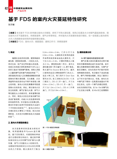
着火房间尺寸取为5.2m×4.6m×2.4m,门开口尺寸为0.9m×2.0m。
火源的形式采用的是软件自带的矩形柴油油池火源形式,尺寸为0.2m×0.3m。
计算时网格大小取为0.1m,模型图如图1所示,其中火源位置见图1所示编号1-6,便于表述,将火源Fire Source简写为FS。
基于FDS的地下单室火灾模拟验证实验
Ma oJ i n f e n g , Zh uGu o d o n g , Xi n gZh e l i a n dZ h o uJ i n
a s t h e r e s e a r c h o b { e c t b a s e d o n he t c h ra a c t e i r s t i c s o f t h e u n d e r g r o u n d b u i l d i n g s i n g l e r o o m, a n d s e t u p a s ma l l s c a l e F i r e
2 0 1 5 年 3月
洁 净 与空 调技 术 C C & A C
第1 期
基于 F D S的地下单室火灾模 拟验证实验
解放 军理 工 大学 国防工程 学院 茅靳 丰 朱 国栋 邢哲理 周 进
摘 要 为 了验 证火灾模拟软件 F DS( F i r e D y n a mi c s S i mu l a t o r )的准确 性 ,针对地下建筑单 室特 点,选取 某工 程 内一个值班 室作 为研究对 象 ,并根 据相似 准则建 立 了小尺度 火灾 房 间模 型。通过 小尺 度单 室火灾实验 ,对 烟 气的扩散 特 性进行 研 究 ,同时利用 F DS模 拟 软件进 行 单 室火 灾模 拟 ,并将 实验结果 与模 拟结果进 行对 比 分析 。结果 表 明,实验 烟气 温度 随 时 间的变化趋 势与 F DS模 拟结 果 一致 ,验证 了火 灾模 拟软 件 F D S的准 确 性 ,证 实 了F DS用 于模拟 预测 单 室火灾 的发展 与迁 移 的适 用 性和合 理性 ,对 火灾 的控 制研 究具有 一定 的参 考价值。 关键词 单 室;模 型 实验 ;数值模 拟 ;F DS
基于FDS的停车楼火灾数值模拟分析

基于FDS的停车楼火灾数值模拟分析摘要:智能化立体式停车楼,机械地下停车楼等大型复杂的现代建筑越来越多地涌现,这些停车楼建筑与传统建筑在使用功能、建筑材料、结构形式、空间大小、配套设施等方面有很大的不同,给防火安全带来很多新的问题,如停车楼这样的大空间建筑物火灾发生之后会非常迅猛并且很难得到控制。
本文利用FDS对以双T板为屋面板的停车楼进行数值模拟分析,通过对比不同板宽及不同火源位置的四种工况,探讨停车楼的火灾发展趋势及火灾防控要点。
关键词:火灾;性能化防火;FDS;停车楼;温度时间曲线引言近些年来,随着我国经济的进步与发展,人均汽车保有量不断提高。
2018年我国千人汽车保有辆为172辆。
按照国际城市建设经验,停车位数量应达到机动车保有量的 1.15 倍,然而我国现有停车位不能满足要求,体现出我国停车位严重不足。
针对我国人口密集,土地资源短缺的情况,发展公共停车楼是今后解决城市停车难问题的主要解决途径。
智能化立体式停车楼,机械地下停车楼等大型复杂的现代建筑越来越多地涌现。
由于停车楼一般空间较大、结构复杂、可燃物数量极多,一旦发生火灾短时间内很难得到控制,给人民群众的生命财产安全带来了极大的危害[1]。
1 停车楼建筑火灾特点停车楼建筑火灾往往比普通建筑火灾严重,其主要有以下几个不同:(1)停车楼空间体积较大,防火和防烟的分区较为困难,当氧气充足时火势蔓极为剧烈;(2)大量汽车被烧毁,火灾荷载较其他普通建筑火灾大很多,产生巨大的浓烟并可能导致爆炸,也使停车楼的预应力承重构件失去抗火能力。
(3)停车楼内灭火时也是十分困难,其结构和功能复杂,火灾发生时很难确定火源的大致位置,加之建筑面积和烟气浓度较大,消防用水很难全面积覆盖,使大空间建筑火灾的扑灭难度加大。
(4)停车楼内火灾一旦发生,逃生通道有限,人员疏散困难,生命安全受到威胁。
同时产生不可估量的财产损失,严重影响社会的和谐发展和经济的稳步增长,也引起了广大人民群众的不满。
基于FDS的倾斜巷道火灾数值模拟与实验研究

基于FDS的倾斜巷道火灾数值模拟与实验研究当前,国内外研究矿井火灾的方法主要有实验研究、数值模拟及理论计算三种方法,其中,实验中很难构建与井下真实环境相一致的实验条件,尤其是在火灾烟气与巷道围岩进行热交换方面很难做到,所以往往采用数值模拟方法来研究矿井火灾,但数值模拟的准确性无法通过现场真实火灾进行验证,为了验证数值模拟的方法和原理的准确性,本文在实验室进行倾斜巷道火灾实验,得到实验室环境下火灾实验的真实数据,利用FDS软件对实验室环境下的火灾实验进行数值模拟,将实验与模拟结果进行分析比较。
本文采用自行设计的巷道火灾实验系统,在无机械通风条件下测得不同倾斜角度的非绝热铁质模型巷道发生火灾时各测点温度、风速及巷道两端压差,同时对不同倾角下的巷道模型壁面温度变化情况进行测量,进而计算出模型巷道壁面的导热量并且得到模型巷道壁面导热量随着巷道倾角增大而减小。
以计算流体力学和传热学为基础,利用FDS建立了与实验模型相同的物理模型,对壁面绝热与非绝热条件进行模拟,得出绝热条件下巷道内温度、风速和巷道两端压差均高于非绝热条件下各参数,其燃烧过程壁面的热量损失对巷道内温度场、速度场与压力场等的影响较大。
将非绝热条件下模拟得到的温度、风速及巷道两端压差等数据,与实验数据进行比较,二者总体变化趋势一致性较好,但结果存在差异,在火灾发展初期及稳定期温度、风速及压力测点的实验测量值均高于模拟值,其主要原因在于模拟时默认模型外部空气温度是恒定温度,而实际情况下模型壁面与室内空气会进行热交换,室内温度会随实验进行而升高,从而影响模拟结果,所以日后在模拟巷道火灾设置边界条件时必须考虑火灾烟气与围岩的热交换。
同时从巷道内流场湍流强度的角度分析了湍流强度对巷道壁面与高温气体间的对流换热的影响,进一步验证了数值模型的准确性。
利用FDS进行火灾现场模拟

T=500s时的火灾发生状况
T=600s时温度分布
FDS应用例-2:隧道火灾模拟
FDS应用例-3:喷淋系统动作模拟
FDS在保险业应用展望
估算可能最大损失(PML) 评估喷淋系统的有效性
结束
对一个5.2m×4.6m×2.4m
的单室进行了火灾模拟,室内设 有沙发、床、椅子、地毯等家具。室内有窗和门,以保证 通风和排烟的目的;房间墙壁是由石膏制成,室内装潢是 由纺织物和泡沫塑料组成。 根据房间的特性和布置情况,起火处设置在沙发上,设定 其热释放率为1,000kw/m2。模拟时间设定为600s。
火灾场景布置
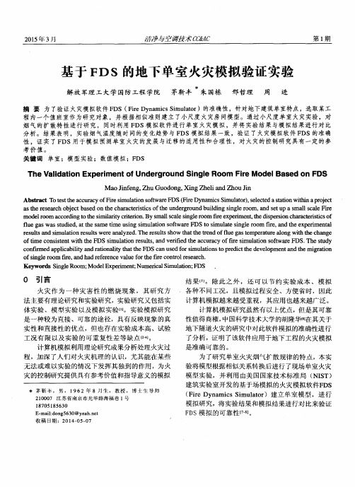
通过对火灾场景的描述,利用FDS软件完整的模拟了单室火灾发生的全 过程。左图显示了在T=500s时的火灾发生情况,从图中可以看出在此 时刻房间内的可燃物全部起燃。右图表示了在T=600s时,X=2.6m 时的 温度分别情况,能够看出单室下部的温度在280℃左右,而上部的温度 已经达到了1,000℃以上。
FDS能模拟下列现象:
• • • • • •
火灾生成热量和燃烧产物的低速输运过程 气体和固体表面的辐射及对流换热 固体燃料的热解 火灾蔓延和火焰传播 喷淋、感热探测器和感烟探测器的启动 喷淋系统的喷洒运动及水对火的抑制
FDS的特点
FDS采用那维尔一斯托克斯方程(粘性流体方程)来对于低速、热驱动流 进行定量计算律。 FDS提供了两种数值模拟方法:直接数值模拟(Direct Numerical Simulation,DNS)和大涡模拟(Large Eddy Simulation,LES)。DNS主 要适用于小尺寸情况下的火焰结构分析,LES则适用于大空间建筑结构 内的烟气流动过程研究。 FDS采用了两种燃烧模型:有限反应率(Finite-rate Reaction)燃烧模 型和混合分数燃烧模型。前者适用于直接数值模拟,后者适用于大涡 模型。 FDS对模拟空间的所有固体表面均赋予热边界条件,并规定了其材料的 燃烧特性,均采用经验公式进行处理。 FDS软件还附带有一个独立的可视化Smokeview程序,用于展示和查看 FDS的模拟计算结果。
利用FDS进行火灾仿真的研究
PRODUCTSSoftware for Architecture, Engineering and Construction CYPE > in English > | Home |CYPE |New features |Products |Versions |Downloads |F.A.Q. | ContactCYPE > english > products > fds > related programsDynamic fire simulation using the Fire Dynamics Simulator (FDS)CYPECAD MEP is a program for the design of the envelope, distributionand services of the building using an integrated 3D model with thevarious elements of the building (dwellings, offices, hospitals, teachingcentres, shops, residential, etc.). It is composed of several modules ortabs, depending on the different types of installations that can bedesigned.The Dynamic fire simulation module, implemented within the Fire(FDS) tab of CYPECAD MEP, is the result of an investigation projectfinanced by the Centro para el Desarrollo Tecnológico Industrial(CDTI), and co‑financed by the European Regional DevelopmentFund (ERDF).This module of CYPECAD MEP carries out dynamic simulations of theevolution of fires in buildings using two external tools (alreadyinstalled in the program): the FDS (Fire Dynamics Simulator)analysis motor and the graphics viewer, SmokeView (SMV), bothdeveloped by the NIST (National Institute of Standards andTechnology, USA). These tools do not have a graphical dataintroduction interface or a useful and easy to use analyticalexpression of the results, and so, other tools are required for theiruse.CYPE’s Dynamic fire simulation module uses the graphical interfaceof the CYPECAD MEP program to provide the FDS motor andSmokeView viewer with the correct and required data (without theuser having to intervene in this communication). It offers a highlyuseful analysis of the results, obtained from an exhaustiveinterpretation of the results calculated by the FDS motor, and all this,without the need of a highly qualified expert in the use of the FDSmotor or fire evolution in buildings.INDEXIntroductionOperating the Dynamic fire simulation moduleActivating the analysis and required data for the dynamic simulationIntroduction of the specific data for the dynamic simulationFire load introductionFire scenario definitionAnalysis carried outCreation of the model for FDSManaging the FDS analysisResults obtainedResults within the CYPE programResults in SmokeViewRecommended hardware and softwareMultiprocessors64 bit operating systemsRelated programsIntroductionCYPE Ingenieros has carried out a project, financed by theCentro para el Desarrollo Tecnológico Industrial (CDTI), andco-financed by the European Regional Development Fund(ERDF), to implement the Dynamic fire simulation module within the CYPECAD MEP program.The Dynamic fire simulation module carries out dynamic simulations of fire evolution in buildings. To do so, it uses two external tools (installed within the CYPE program):Analysis motor For the analysis motor, the program uses the computational fluid dynamics model known as FDS (Fire Dynamics Simulator), developed by the NIST (National Institute of Standards and Technology, USA).3D viewer For the 3D graphics viewer of the evolution of the fire,SmokeView (SMV) is used, also developed by NIST.Neither tool has a graphical data introduction interface, and so the data must be introduced using text files organised in a specific way. On the other hand, the FDS motor generates,within its analysis process, a large amount of information on the fire simulation which has been undertaken. The analysis of this information is highly complex and laborious, and requires vast experience on behalf of the user to be able to express it in a useful manner.CYPE’s Dynamic fire simulationmodule uses the graphical interface of its CYPECAD MEP software to provide the FDSmotor with the correct and required data, and the SmokeViewviewer with the necessary results for a 3D animation of theresults to be obtained. All this, without the user having to intervene. CYPE’s program also analyses and interprets theresults which have been calculated by the FDS motor andgenerates control points which appear on the plan view of the Fire (FDS) tab of the CYPECAD MEP program, where the usercan obtain reports containing time graphs of the evolution of the variables monitored in the simulation.The Dynamic fire simulation module allows the user to locatethe seat of the fire at any point in the building to validate the behaviour of the smoke of the fire and check the viability of the evacuation. It can also be used for existing buildings, allowing the user to verify if the design of the building can be improved even if it already fulfils the requirements of the corresponding code.There are many factors which influence the safety of the building in case of a fire. Amongst them is the concentration and temperature of the smoke, as high levels can hinder the correct evacuation, risk the integrity of the occupants, and even aid in the structural collapse of the building. The width of the corridors, the quality of the materials and fire protection installation are some of the parameters this software takes into account, and are linked to all the CYPECAD MEP programs developed by CYPE. This allows the user to check and visualise the design alongside the corresponding design code.There is currently no other similar technology, and so the program can be of great use to Fire fighters and engineers responsible for the design of fire suppression systems and temperature control and smoke evacuation systems.More detailed information on the data introduction and the results provided by CYPE’s Dynamic fire simulation module can be found in the following sections.Operating the Dynamic fire simulation moduleActivating the analysis and required data for the dynamic simulationThe analysis of the simulation is carried out within the Fire (FDS) tab of the CYPECAD MEPprogram. Within the FDS menu of this tab, all the options required to define the simulation can be found (except the Fire loads option which can be found in the Installation menu within the same tab). These options are usually defined before the analysis. Nonetheless, the simulation can be initiated at any moment using the Analyse fire simulation option within the FDS menu (even if no other parameters have been defined) and the program will emit a warning indicating there is data missing: definition of fire scenarios, selection of building precincts to be included in the simulation,definition of fire loads and selection of the fire initiation element.Additionally, to analyse the dynamic simulation of the building, the construction elements of thebuilding must be introduced, as well as defining its precincts and, if required, fire installation protection elements such as automatic sprinklers, fire or smoke detectors are also to be introduced and are processed as such in the FDS model. If the evacuation paths are also defined, the program monitors the evolution of the smoke along the evacuation paths, which provides valuable information on the evolution of the temperature and smoke at places crossed by those paths.Introduction of the specific data for the dynamic simulationFire load introductionTo define the scene of the simulation correctly, the combustible elements occupying or furnishing the precincts where the fire will develop or can extend to, have to be introduced in the model, as these will be the main fire loads which feed and determine how the fire will evolve.For this, the program includes a tool to introduce the combustible solids (Installation > Fire loads), with an associated common combustible materials library, containing the required data for the FDS model, such as combustion and vaporisation enthalpies,pyrolysis, heat release rates, loss of mass, etc.The construction elements making up the geometric model of the building are characterised automatically in the FDS model, achieving a simple, easy and intuitive introduction of the combustible and non-combustible elements in the simulation.Fire scenario definitionTo create the fire models which the FDS motor will analyse, a tool can be used which manages the different fire scenarios in the building, so that, in a single file for the whole building, different fire scenarios and their corresponding results from the dynamic simulation can be managed. This way, data introduction is greatly simplified and the elaboration of new fire scenarios and the analysis of each of their results can be carried out in a more agile manner. This also allows the user to compare and analyse different fire scenarios within the building, to obtain a better understanding of the positive aspects and errors of the design,and so reaching the most optimum configuration for temperature control and smoke evacuation.These fire scenarios are created using the Fire scenario option within the FDS menu . Theprogram allows the user to create, copy and edit the different fire scenarios of the building, and select any of them and work on their associated data, which includes:Selection of the building precincts This selection is carried out using the following menu:Selection of precincts to include in the simulation ,within the FDS menu. The number of precincts included in the simulation will determine the size of the model which is launched in the analysis, and hence, the time required to analyse it.Selection of the elements initiating the fire The selection of the load or fire loads which begin to burn at the start of the simulation is carried out using the following option: Selection of fire initiation elements ,within the FDS menu.Status of the openings The status (whether open or closed) of the openings present in the building, such as doors or windows, will determine the air flow of the fire and, therefore, its evolution. To open or close an opening, use the following option: Behaviour of openings in the simulation , withinthe FDS menu.Apart from this information, the FDS model that is generated for each fire scenario includes control logics which allow for certain changes to be carried out on the model during the simulation.So, windows or skylights which start off as closed in thesimulation , can break at a particular moment of the simulationif the necessary pressure and temperature conditions arise, and so the ventilation conditions can vary during the simulation. Additionally, if sprinklers or heat or smoke detectors have beendefined, these are linked with a logic which simulates the fire alarm signal of the building, with some delay, which allows to act upon other elements of the building, such as closing of magnetic retention firebreak doors or the opening of smoke vents for smoke evacuation at roof level. Thevideo displays an example of the simulation carried out by the program . Here, it can be seen how at a particular moment, the smoke vents on the roofs open (with the consequent reduction of theaccumulated smoke layer inside the warehouse) and the sprinklers of the fire protection installation come into action.Analysis carried outCreation of the model for FDSHaving introduced all the necessary data correctly, and using the Analyse fire simulation option from the FDS menu, any of the defined fire scenarios can be analysed. Upon executing this option, the General data configuration window will open, together with the list of fire scenarios defined for the building.Within this window, the only thing left to do is choose thescenario to simulate and define two essential parameters for theanalysis of the dynamic simulation: the cell size of the mesh ofthe FDS model and the duration of the simulation.The cell size for the discretisation defines the precision of themesh of the building FDS model and determines the number ofcells the analysis must manage, which is directly proportional tothe time taken to analyse the simulation and the memory spacerequired to carry it out.15, 20 or 25 cm cell size values are considered to be sufficiently precise to analyse the behaviour of the smoke of the fire in large volumes. Nonetheless, in early phases of the behavioural study of the building on fire, faster simulations can be undertaken by introducing higher mesh values. Sizes smaller than 15 cm imply a very dense analysis and are only required for fire and smoke analysis studies in reduced volumes.The duration of the simulation determines the real time of thefire evolution to analyse and begins with the ignition of the fireloads established as the initiation elements. The FDS analysismotor is valid to analyse the behaviour of the smoke and fire, andso is useful to study its early phases, including the evacuation ofthe occupants of the building. However, it is not valid to simulatethe possible structural collapse of the building, and so simulationswhich last longer than 30 minutes are not recommended ornecessary.A feature worth highlighting ofthe program, compared toother modelling tools for theFDS, is the completeindependence of the buildingmodel with respect to the cellsize and mesh of the FDS model. In other words, the 3D model ofthe building, which is managed and edited in the program(shared with the other CYPECAD MEP analysis models)corresponds to the model with the real dimensions of eachelement present within it; and the model that is exported to theFDS motor (which is created automatically when the dynamicsimulation of the building is initiated) is specific for the scenario selected by the user (with the precinct subgroup it contains and the chosen discretisation), and is optimised for the number of processors used in the analysis and for the configuration of construction and combustible elements present in the simulation.This manner of working allows the user to forget many of the limitations of the FDS model, such as the alignment of the meshes or having to define obstacles (OBST entities of the model), as the program builds the model adjusting itself to the chosen cell size, modifying the thermal properties of the materials or objects, in such a way that the resultant model can be analysed without any problems for the FDS motor, in a minimum amount of time, and respecting the thermal behaviour of the real model. This presents an obvious advantage for the study of the dynamic behaviour of the fire within the building: it allows for different versions of the model to be simulated, with more or less details (i.e. more or less complex to analyse) by simply varying the cell size.Managing the FDS analysisOnce the model for the FDS has been created, a window willopen automatically which manages the dynamic analysis. Theprogram uses the optimum FDS motor in the computer at which itis executed (32 or 64 bit and with processors in one or severalCPU s). The last version of the Dynamic fire simulation programalways includes the last validated version of the FDS published bythe NIST.This manager window of the FDS analysis is opened as an independent process, which allows the user to continue working on the model, defining other fire scenarios or buildings, whilst the analysis of the simulation is taking place.Within this window, the user can view the duration of thesimulation analysis, and the estimated remaining time; the realduration of the achieved simulation; buttons to view thegenerated *.fds file and, launched for the simulation, the outputfile, *.out, which is generated by the FDS motor; and the buttonto activate SmokeView with the data of the simulation oncourse.Using SmokeView, which has been developed by the NIST and ispartner of the FDS analysis motor, the results of the simulationcan be accessed up to the analyses moment whilst the analysis isstill taking place. This allows for the evolution of the smoke withtime to be explored as well as the fire temperature, in acompletely 3D visual manner, as well as allowing the user to study the repose of the detection and alarm systems of the building or, even, the activating and working of the automatic sprinklers. From the management window of the dynamic simulation analysis, the analysis on course can also be stopped and results can be obtained as of the first instant of the simulation up to the moment reached in the analysis. It is also possible to continue with the analysis as of the moment it was stopped, allowing for it to be dealt with in different stages.Results obtainedResults within the CYPE programAfter the analysis, the FDS motor generates a vast amount ofinformation on the fire simulation that has been carried out. Theanalysis of this information is highly complex and laborious, andrequires a lot of experience on behalf of the user to be able toexpress it in a useful way. The Dynamic fire simulation modulecontains a tool which post-processes and generates the resultsof the simulation carried out by the FDS motor so it can beanalysed with the CYPE program.This tool can be activated using the Show simulation resultsoption within the FDS menu. Once activated (in jobs withcompletely analysed fire scenarios or paused at a particularmoment), control points appear on the plan view of the building.Depending on the control point at which the user places thecursor, the following information appears on screen:Activation of smoke or heat detectorsActivation of sprinklersAlong the evacuation paths, the following are displayed:The instants when dangerous temperatures areexceeded in the smoke layerWhen the smoke-free height falls below 2mBy clicking on any of thesecontrol points using the leftmouse button, reports aregenerated, which include graphsthat display how the followingfactors evolve in time during thesimulation:The temperature insprinklers or heatdetectorsThe degree of darknessin smoke detectorsThe temperatures of the cold layer and smoke layer, and the smoke free height(parameters which are required for the SCTECH design in accordance with EN 12101-5:2005) along the established evacuation paths of the building.Results in SmokeViewApart from the control points and columns generated within the FDS model, which are then post-processed to obtain results graphs in the program, upon generating the FDS model, certain control planes are added so they can be inspected in the SmokeView viewer.For each floor of the building which is analysed in the simulation, temperature distribution planes are added, as well as air velocity control planes and visibility defree planes in metres. This way, within the SmokeViw viewer, as well as the being able to represent the smoke and fire which isgenerated, the evolution of these magnitudes in horizontalplanes can also be represented per floor. Therefore, with thistool, the user can rapidly judge how the building and its smokeevacuation and temperature control systems behave.Recommended hardware and softwareThe complexity of a fire dynamics simulation of a building and themultiple factors which intervene, implies the computer at whichthe simulation is going to be analysed has more hardware andsoftware requirements than those required to operate normal programs. Emphasis is especially given to the possibility of using processors with several nuclei and the operating system of the computer where the simulation is going to be analysed.MultiprocessorsThe Dynamic fire simulation module can work with another module of CYPE, Parallel analysis with up to eight processors. This way the user can make the most of the division capacity of the analysis work of the simulation in different FDS model meshes so it can be processed in parallel and that of modern CPUs containing several nuclei, and the lengthy analysis time of the dynamic fire simulations is reduced. To be able to carry out complex simulations, it is essential CYPE’s Parallel analysis with up to eight processors module be included in the user license.64 bit operating systemsBoth the FDS analysis motor and the SmokeView results viewer work on computers with 64 bit operating systems, and so it is possible to carry out complex simulations with a high number of cells which are generated, either due to the building zone which is to be simulated, or because of the reduced size of a unit cell. Thanks to this, the RAM memory restrictions imposed on 32 bit processors (2 GB per process) are eliminated.Simulation models containing more than 2 million cells cause memory problems to arise in 32 bit operating systems. The program emits a warning of this upon generating the model, which allows the user to correct the size of the zone to simulate, or increase the unit cell size, so to create a mesh with a lower number of cells.In any case, to be able to carry out complex simulations, either due to their large size or their dense mesh, or because automatic extinguishing systems come into use in the simulation (fire extinguishing using automatic sprinklers), it is always recommended that 64 bit operating systems be used and if possible these be associated with a CPU with several nuclei and a RAM memory greater than 4 GB.Related programsCYPECADSteelMetal 3DPortal frame generatorContinuous beamsSoil retention elementsCantilever retaining wallsEmbedded retaining wallsCivil worksBox culvertsArquimedes. Create, manage and control bills of quantities, project certifications andspecificationsCYPECAD MEPAir conditioningDynamic fire simulationTop©CYPE Ingenieros, S.A. - Avda. Eusebio Sempere, 5 - 03003 ALICANTE. SpainTel. USA (+1) 202 569 8902 // UK (+44) 20 3608 1448 // Spain (+34) 965 922 550 - Fax (+34) 965 124950Home | CYPE | Products | Versions | Downloads | Contact usBulgarian | French | Italian | Portuguese | Spanish | Spanish (Mexico) | Other dealerships。
基于FDS的室内火灾动力学研究
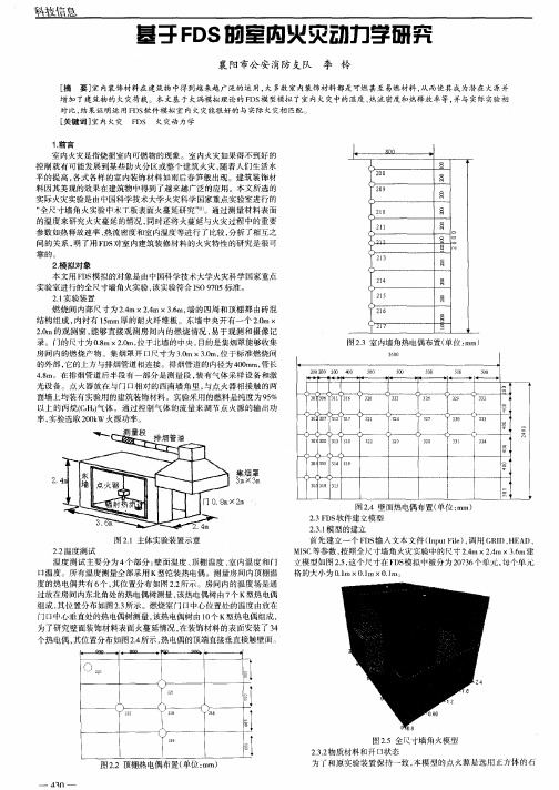
室内火灾是指烧损室 内可燃物的现象 。室 内火灾如果得不到好 的 控制就有 可能发展到某些 防 火分区或整个 建筑火灾 , 随着人们生活水 平 的提 高 , 各式各样 的室内装饰材料 如雨后春笋般 出现。建筑装饰材 料因其美观 的效果在建筑物 中得到 了越来越广泛 的应用 。本文所选 的 实际火灾实验是 由中国科学技术大学火灾科学 国家重点实验室进行 的 “ 全尺 寸墙角火实验 中木丁板表面火蔓延 研究” 。通 过测量材料表 面
盖息
基于 F ¥的室内火灾动力学研究 D
襄 阳市公安 消防 支队 李 铃
[ 摘 要] 内装饰材料在 建筑物 中得 到越 来越 广泛的运用 , 多数室 内装饰材料都是可燃甚至 易燃材料 , 室 大 从而使其成为潜在 火源并 增加 了建筑物的 火灾荷载 。本文基 于大涡模拟理论的 F 模 型模拟 了室内火灾中的温度 、 DS 热流密度和热释放率等 , 并与 实际实验相 对 比 , 果 证 明 运 用 F 软 件 模 拟 室 内火 灾 能很 好 的 与 实 际 火 灾相 匹配 。 结 DS [ 关键词 ] 室内火灾 F 火灾动力学 DS
格 的大 小 为 01 .m×0I ×01l .m .n。
为了研究壁面装饰材料表面火蔓延情况, 在装饰材料的表面安装了3 4
个热 电偶 , 其位置分布如图 2 所示 , . 4 热电偶 的顶端 直接垂直接触壁面 。
0 。
,
, L 、
, ,
,
、
1 8
图25全尺寸墙角火模型 .
网2 . 3室内墙角 热电偶 布置 ( 单位 : m) l ' n
_ n
50 0
2 0 2 20 0 00 0
40 0
- 1、下载文档前请自行甄别文档内容的完整性,平台不提供额外的编辑、内容补充、找答案等附加服务。
- 2、"仅部分预览"的文档,不可在线预览部分如存在完整性等问题,可反馈申请退款(可完整预览的文档不适用该条件!)。
- 3、如文档侵犯您的权益,请联系客服反馈,我们会尽快为您处理(人工客服工作时间:9:00-18:30)。
科学技术2010.7 75FDS 模拟火灾的实验研究于慧鸣鞍山市消防支队 辽宁 鞍山 114000【摘 要】本文使用FDS 火灾模型模拟火灾,分析建筑内发生火灾时,可燃物的数量对于烟气层高度、温度和能见距离的影响情况,得出危险指标与各影响因素之间的关系。
【关键词】烟气层高度 能见距离 FDS 火灾模型一、绪论由于当烟气层高于人眼特征高度(人眼的特征高度通常为1.3~1.8 m,我们取1.5 m),烟气层温度达到180 ℃时,则其产生的热辐射就会对人体造成不可恢复的烧伤;当烟气层高度低于人眼特征高度,烟气层温度达到115 ℃时,就会对人体构成危险。
本文使用FDS 火灾模型模拟火灾,分析建筑内发生火灾时,可燃物的种类和数量等因素对于烟气层高度、温度和能见距离的影响,得出危险指标与各影响因素之间的关系。
二、利用FDS 模拟火灾1、FDS 火灾模型简介FDS 火灾模型包括两大部分。
第一部分简称FDS4,是求解微分方程的主程序,需要用户创建文本来描述火灾场景;第二部分称SMOKEVIEW,可以直观的查看计算结果。
FDS 的输入文件分成三部分:第一部分为几何参数和网格的设置;第二部分为有关燃烧过程的设置,如燃烧时间、火源功率、通风口的设置等;第三部分为输出数据的设置,如某点或某个面上的温度、密度、混合组分在火灾过程中随时间的变化情况等。
2、FDS 模拟火灾 (1)参数设定为了准确地求解火灾的相关问题,设置基本参数如下:①设置烟的减光系数与能见距离之积C=1(系统默认值为3)。
对于发光物质来说C=8,对于反光物质来说C=3,但在性能化评估中为保守起见通常取C=1,因此,本文取C=1。
②室内温度为20 ℃;(2)火灾模拟图2.1 模拟火灾基本模型如图2.1所示模拟火灾的基本模型,建立两间尺寸均为4.0 m×4.0 m×4.0 m 房间,本文以房间1作为分析对象,设置床为火源且热释放速率稳定。
在本文中,由于主要分析可燃物数量等因素对临界危险指标的影响情况,因此,如表2.1中给出了三种火灾模拟方案进行火灾模拟。
表2.1 摸拟火灾方案方 案 热释放速率/Kw 窗口面积/m2 可燃物 方案1 方案2 方案3 1656 2208 2760 3.00 3.00 3.00 木材 木材 木材 说明:方案1.1~1.3为改变可燃物数量;方案2.1~2.3为改变可燃物种类。
表2.1所列方案中,选取可燃物的单位面积的热释放速率为300Kw/㎡、400 Kw/㎡和500 Kw/㎡三种情况来表示可燃物数量的改变,因为床为火源,其与空气接触的面积为5.52 ㎡,所以可燃物的热释放速率分别为1656 Kw、2208 Kw 和2760 Kw。
在FDS 火灾模型输入文本中输入相关参数,同时输入需要分析的数据:烟气层高度、温度和能见距离等,在DOS 模拟窗口下,运行FDS 进行运算。
由于运行FDS 耗费计算机资源较大,在模拟火灾发生30s 左右,所有危险指标均已达到稳定状态,因此,为节省运算时间,本文火灾模拟时间取t=50s。
(3)网格尺寸的确定对于划分网格比较粗略的模型,则计算结果不精确;若网格过密,则FDS 运行时间过长,因此为使计算结果精确同时又节省运算时间,本文通过确定火灾直径D *来确定计算网格单元的尺寸*D =(2.1)式中:D *是火灾直径,m;Q 是热释放速率,Kw;ρ∞是空气密度,Kg/m 3;Cp 是空气的比热,J/(Kg·℃);T∞是空气的温度,℃;g 为重力加速度,m/s 2。
在本文中,热释放速率共有三种情况即1656 Kw、2208 Kw 和2760 Kw.因此由式(2.1),分别计算三种情况的火灾直径如下:*1D m =*2D m =*3D m =由于火灾直径均在1.0 m 左右,因此,统一火灾直径取D*=1.0 m,由此确定网格尺寸为△x=△y=△z=0.1D*=0.1 m;三、模拟结果分析表2.1中具体给出了方案的设置参数,即设置床为火源,可燃物为木材,窗户的开口面积为3.00 m 2,可燃物的热释放速率分别为以下三种情况:HRR1=1656 Kw;HRR2=2208 Kw;HRR3=2760 Kw。
1、改变可燃物数量对烟气层高度的影响1.61.61.61.61.71.71.71.71.71.81.81.8l a y e r h e i g h t / mH R R / K w图3.1 改变可燃物数量对烟气层高度的影响图3.1中各点给出了可燃物的热释放速率分别为1656 Kw、2208 Kw 和2760 Kw 的三种情况下模拟火灾的烟气扩散达到相对稳定状态以后(25~50 s)的平均烟气层高度值,分析得出:(1)烟气层的高度随着可燃物热释放速率的升高即可燃物数量的增加而降低;(2)可燃物的数量越多越不利于建筑物排烟。
如图3.2(a)和(b)直观的给出了模拟火灾的烟气扩散达到相对稳定以后(选取35 s 时)热燃烧速率分别为HRR1=1656 Kw;HRR3=2760 Kw 的情况下的烟气层状态:科学技术2010.776(a) 35 s 时HRR 1的烟气 (b) 35 s 时面积HRR 3的烟气图3.2 改变开口面积对烟气层的影响2、 改变可燃物数量对温度的影响图3.3 改变可燃物数量对温度的影响图3.3中各点给出了可燃物的热释放速率分别为1656 Kw、2208 Kw 和2760 Kw 三种情况下模拟火灾的上、下层温度(h 1=3.5 m 和h 2=2.0 m 处)达到稳定状态以后(25~50 s)的平均温度值,分析得出:(1)上、下层温度随着可燃物热释放速率的升高即可燃物数量的增加而升高;(2)上、下层的温差随着可燃物热释放速率的升高而降低。
如图3.4(a)和(b)直观的给出了模拟火灾的温度变化达到相对稳定以后(选取35 s 时)热燃烧速率分别为HRR 1=1656 Kw;HRR 3=2760 Kw 的情况下的h=2.0 m处的温度状态:(a) 35 s 时HRR 1的温度情况 (b) 35 s 时HRR 3的温度情况图3.4 改变开口面积对温度的影响3、改变可燃物数量对能见距离的影响图3.5 改变可燃物数量对能见距离的影响图3.5中各点给出了可燃物的热释放速率分别为1656 Kw、2208 Kw 和2760 Kw 三种情况下烟气扩散达到稳定状态以后(25~50 s)的平均能见距离(h=2.1 m 处),分析得出:(1)能见距离随着可燃物热释放速率的增大即可燃物数量的减少而增大;(2)可燃物数量越少越有利于火场中人员逃生。
四、结论本文应用FDS 建立了火灾模拟的基本模型,在分别可燃物数量情况下,对烟气层高度、温度和能见距离等危险指标的影响情况进行分析,得出以下结论:(1)烟气层的高度随着可燃物数量的减少的降低而升高; (2)温度随着可燃物数量的减少而降低;(3)能见距离随着可燃物数量的减少而增大。
参考文献[1] 公安部消防局. 中国消防年鉴[M]. 北京:中国人事出版社, 2004.[2] 张吉光, 史自强, 崔红杜. 高层建筑和地下建筑通风与防排烟[M]. 北京:中国建筑工业出版社, 2005.[3] 李引擎. 建筑防火性能化设计[M]. 北京:化学工业出版社, 2005.5.[4] 公安部政治部编. 建筑防火设计原理[M]. 北京:中国人民公安大学出版社, 1997.[5] fds_users_guide_4.(上接第77页)也可以在作业中采用RTK测量模式的优势,准确快速地建立图根控制点,在图根控制点上由全站仪配合电子手簿进行碎部点的数据采集。
该法不像常规图根导线测量那么烦琐,受地形的限制,也不用支仪器设站,从而减少了因多次设站带来的测量累计误差,提高了全站仪碎部点采点的点位绝对精度,使地形测量方便快捷,大大提高了地形测量的工作效率。
在地形图、地籍图等的测量应用中,均取得了很好的效果。
4、结论4.1 RTK 技术操作简便,灵活方便,工作状态稳定。
能快速、准确地测定图根点、碎部点的坐标和高程,实时提供精度可达厘米级经检核的三维坐标。
与传统的测图方法相比,人员少,费用省,效率高。
4.2 基准站的选择对于RTK 测量非常重要,它将直接影响到流动站的施测精度和测量速度,应注意二者之间的“通视”。
4.3 应根据测区的实际情况选择合适的坐标转换参数求解方法,参与坐标转换的已知点应在3个以上,且分布要均匀,做到在满足精度要求的情况下,尽可能的减少外业的工作强度。
4.4在山区地形测量中,GPS一RTK技术可以替代全站仪进行图根导线测量,所测范围内在不通视的条件下测定无累积误差的图根点,使测图所需图根点的数量在满足要求时,可多可少,机动灵活;而且移动点至基准点的距离可以很长(最好不要超过10 km)。
4.5在个别高大建筑物或建筑稠密地区,GPS出现盲区,初始化时间长或失锁,影响碎部测量速度,可采用RTK增补图根导线点,配合全站仪测量碎部点的方法,从而快速地完成野外作业,也可以大大提高外业测图的工作效率,进而达到缩短工期,节约成本的目的。
参考文献[1] 孔祥元,梅是义;控制测量学(上,下);武汉测绘科技大学出版社;1996年。
[2] 《城市测量规范》;CJJ 8-99;建设部颁布;1999年。
[3] GB 7931-87,1:500,1:1000,1:2000地形图航测摄影测量外业规范[S]。
[4] 徐绍铨,张华海,杨志强; GPS 测量原理及应用;武汉测绘科技大学出版社;1997年。
[5]武汉测绘科技大学测量平差教研室编著;测量平差基础;测绘出版社;1996年。