CLARKE柴油机说明书剖析
柴油发动机说明书(中文)

En dansk version af denne instruktionsbog kan bestilles gratis, op til 12 måneder efter levering, via internet, post eller telefax. Se bestillingsformular i slutningen af bogen. Alle oplysninger gemmes internt hos AB Volvo Penta og overgives ikke til tredje part.
Hay disponible una versión en español gratuita de este manual de instrucciones, la cual puede pedirse, a través de Internet, correo postal o fax, en el plazo de 12 meses después de la entrega del producto. Véase el formulario de pedido en las últimas páginas del manual. Todos los datos recibidos son almacenados de forma interna por Volvo Penta AB y no se ponen a disposición de terceras partes.
Een Nederlandse versie van dit instructieboek kan kosteloos worden besteld tot 12 maanden na aflevering, internet, post of fax. Zie het bestelformulier achterin het boek. Alle gegevens worden intern opgeslagen bij AB Volvo Penta en niet verstrekt aan derden.
柴油发动机手册说明书

Eaton 073189Eaton Moeller® series A-PKZ0 Shunt release (for power circuitbreaker), 380 V 50 Hz, Standard voltage, AC, Screw terminals, Foruse with: Shunt release PKZ0(4), PKEGeneral specificationsEaton Moeller® series PKZ Shuntrelease073189401508073189468 mm90 mm24 mm0.129 kgCECSAULCSA File No.: 165628UL Category Control No.: NLRV UL 508CSA Class No.: 3211-05IEC/EN 60947-4-1CSA-C22.2 No. 14UL File No.: E36332A-PKZ0(380V50HZ)Product Name Catalog NumberEANProduct Length/Depth Product Height Product Width Product Weight Certifications Model CodeScrew connectionAccessories Motor safety switch Motor protective circuit-breaker ACCan be fitted to left side of the motor protection switch-25 °C55 °C2 x (0.75 - 2.5) mm² 1 x (0.75 - 2.5) mm²1 x (18 - 14)2 x (18 - 14)0.7- 1.1 x Us (DC) 0.7 - 1.1 x Us (AC)0.7- 1.1 x Us (alternating voltage)42 V480 V24 V250 V0.7- 1.1 x Us (DC) 0.7 - 1.1 x Us (AC)0.7- 1.1 x Us (alternating voltage)Electric connection type Product category Suitable for Used withVoltage type Mounting positionAmbient operating temperature - min Ambient operating temperature - max Terminal capacity (solid/flexible with ferrule)Terminal capacity (solid/stranded AWG)Operational voltage Rated operational voltage (Ue) at AC - min Rated operational voltage (Ue) at AC - max Rated operational voltage (Ue) at DC - min Rated operational voltage (Ue) at DC - max Operational voltage Number of contacts (change-over contacts)Number of contacts (normally closed contacts)380 V 380 V 0 V0 V0 V0 V 05 VA, Pull-in power, Coil in a cold state and 1.0 x Us 5 VA, Pull-in power, Coil in a cold state and 1.0 x Us 3 VA, Coil in a cold state and 1.0 x Us3 VA, Coil in a cold state and 1.0 x Us0 W0 W0 W0 A0.5 WMeets the product standard's requirements. Meets the product standard's requirements. Meets the product standard's requirements. Meets the product standard's requirements. Meets the product standard's requirements.Motor Starters in System xStart - brochureMotor-Protective Circuit-Breaker PKE - brochurePKE – Communication module Modbus RTUProduct Range Catalog Switching and protecting motorsDA-DC-00004206.pdfDA-DC-00004108.pdfDA-DC-00004601.pdfDA-DC-00004109.pdfDA-DC-00004316.pdfDA-DC-00004545.pdfDA-DC-00004244.pdfDA-DC-00003914.pdfDA-DC-00004246.pdfDA-DC-00004230.pdfDA-DC-00004069.pdfDA-DC-00004554.pdfDA-DC-00004245.pdfDA-DC-00004880.pdfRated control supply voltage (Us) at AC, 50 Hz - min Rated control supply voltage (Us) at AC, 50 Hz - max Rated control supply voltage (Us) at AC, 60 Hz - min Rated control supply voltage (Us) at AC, 60 Hz - max Rated control supply voltage (Us) at DC - minRated control supply voltage (Us) at DC - max Number of contacts (normally open contacts)Power consumption, pick-up, 50 HzPower consumption, pick-up, 60 HzPower consumption, sealing, 50 HzPower consumption, sealing, 60 HzEquipment heat dissipation, current-dependent PvidHeat dissipation capacity PdissHeat dissipation per pole, current-dependent PvidRated operational current for specified heat dissipation (In) Static heat dissipation, non-current-dependent Pvs10.2.2 Corrosion resistance10.2.3.1 Verification of thermal stability of enclosures10.2.3.2 Verification of resistance of insulating materials to normal heat10.2.3.3 Resist. of insul. mat. to abnormal heat/fire by internal elect. effects10.2.4 Resistance to ultra-violet (UV) radiation BrochuresCataloguesCertification reports Declarations of conformityDoes not apply, since the entire switchgear needs to be evaluated.Does not apply, since the entire switchgear needs to be evaluated.Meets the product standard's requirements.Does not apply, since the entire switchgear needs to be evaluated.Meets the product standard's requirements.Does not apply, since the entire switchgear needs to be evaluated.Does not apply, since the entire switchgear needs to be evaluated.Is the panel builder's responsibility.Is the panel builder's responsibility.Is the panel builder's responsibility.Is the panel builder's responsibility.Is the panel builder's responsibility.The panel builder is responsible for the temperature rise calculation. Eaton will provide heat dissipation data for the devices.Is the panel builder's responsibility. The specifications for the switchgear must be observed.Is the panel builder's responsibility. The specifications for the switchgear must be observed.DA-DC-00004883.pdfDA-DC-00004878.pdfDA-DC-00004882.pdfDA-DC-00004884.pdfDA-DC-00004935.pdfDA-DC-00004916.pdfDA-DC-00004912.pdfDA-DC-00004945.pdfDA-DC-00004892.pdfDA-DC-00004960.pdfDA-DC-00004890.pdfDA-DC-00004888.pdfDA-DC-00004886.pdfDA-DC-00004913.pdfDA-DC-00004891.pdfDA-DC-00004950.pdfDA-DC-00004961.pdfDA-DC-00004920.pdfDA-DC-00004915.pdfDA-DC-00004910.pdfDA-DC-00004887.pdfDA-DC-00004914.pdfDA-DC-00004952.pdfDA-DC-00004962.pdfDA-DC-00004937.pdfDA-DC-00004944.pdfDA-DC-00004787.pdfDA-DC-00004851.pdfDA-DC-00004953.pdfDA-DC-00004885.pdfDA-DC-00004921.pdfDA-DC-00004889.pdfDA-DC-00004918.pdfDA-DC-00004919.pdfDA-DC-00004881.pdfDA-DC-00004917.pdfeaton-manual-motor-starters-release-u-pkz0-accessory-dimensions.eps eaton-manual-motor-starters-shunt-releases-u-pkz0-accessory-3d-10.2.5 Lifting10.2.6 Mechanical impact10.2.7 Inscriptions10.3 Degree of protection of assemblies10.4 Clearances and creepage distances10.5 Protection against electric shock10.6 Incorporation of switching devices and components10.7 Internal electrical circuits and connections10.8 Connections for external conductors10.9.2 Power-frequency electric strength10.9.3 Impulse withstand voltage10.9.4 Testing of enclosures made of insulating material10.10 Temperature rise10.11 Short-circuit rating10.12 Electromagnetic compatibility DrawingsEaton Corporation plc Eaton House30 Pembroke Road Dublin 4, Ireland © 2023 Eaton. All rights reserved. Eaton is a registered trademark.All other trademarks areproperty of their respectiveowners./socialmediaThe device meets the requirements, provided the information in the instruction leaflet (IL) is observed.drawing.epseaton-manual-motor-starters-release-u-pkz0-accessory-3d-drawing.eps DA-CE-ETN.A-PKZ0(380V50HZ)IL03402034ZVideo Motor Protective Circuit Breaker PKEWIN-WIN with push-in technologyDA-CS-a_pkzDA-CD-a_pkzeaton-manual-motor-starters-release-a-pkz0-shunt-release-wiring-diagram.eps10.13 Mechanical functioneCAD modelInstallation instructionsInstallation videosmCAD modelWiring diagrams。
伯克尼斯4.203.2直流柴油发动机的零件说明书
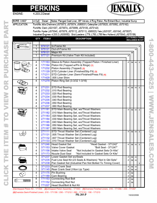
(4)Oversize Semi-Finished Liners: .010 - 171139 / .030 - 171212 / .050 - 171112 / .100 - 171213PK-203-P 10/22/2006APPLICATION: Forklifts: Allis Chalmers (JG70073, JG70074, JG80031) Caterpillar (JG70020, JG70092, JG70162)Forklifts: Clark (JG31037, JG70074, JG70099, JG70100, J G70143)Forklifts: Hyster (JG70040, JG70076, JG70112, JG70113, JG80023) Yale (JG31037, JG31042, JG70037)Industrial Engines: 4.203.2 (JG30052) Skid Loaders: L779, L783, L785 New Holland (JG70043, JG70156)QTY ITEM # DESCRIPTION LETTERED ITEMSINCLUDED IN KIT1 974121 In-Frame Kit I1 975121 Out-of-Frame Kit O1 976121 Major Kit M1 977121 Premium Kit (Valve Train Kit Included) P4 171163 Sleeve & Piston Assembly (Topped Piston / Finished Liner) P M O I4 171164 Piston Kit (Topped w/Pin & Rings) (1)4 171232 Piston Assembly (Topped) (2)4 171129 STD Cylinder Liner (Finished/Slip Fit) (3)4 171211 STD Cylinder Liner (Semi-Finished/Press Fit) (4)4 171429 .005 Liner Shim4 171279 Piston Ring Set (3-3/32 1-3/16)4 271231 STD Rod Bearing P M O I4 271232 .010 Rod Bearing4 271233 .020 Rod Bearing4 271234 .030 Rod Bearing4 271235 .040 Rod Bearing4 271236 .050 Rod Bearing4 271237 .060 Rod Bearing1 271181 STD Main Bearing Set, wo/Thrust Washers P M O I1 271182 .010 Main Bearing Set, wo/Thrust Washers1 271183 .020 Main Bearing Set, wo/Thrust Washers1 271184 .030 Main Bearing Set, wo/Thrust Washers1 271185 .040 Main Bearing Set, wo/Thrust Washers1 271186 .050 Main Bearing Set, wo/Thrust Washers1 271187 .060 Main Bearing Set, wo/Thrust Washers1 271111 STD Thrust Washer Set (Centered Lug) P M O I1 271131 .005 Thrust Washer Set (Centered Lug)1 271132 .007 Thrust Washer Set (Centered Lug)1 271133 .010 Thrust Washer Set (Centered Lug)1 371246 Head Gasket Set "Head Gasket - 371242" P M O I1 371153 Valve Cover Gasket "Bolt Seal - 371247" 4 371158 Intake Valve Seal "Not Included In Gasket Sets Or Kits"4 371173 Nozzle Dust Seal "Not Included In Gasket Sets Or Kits"1 1 1 371237 371235 371238 Lower Gasket Set wo/Seals Fuel Line Seal Kit (23 Seals & Washers) "Not In Gkt Sets" Pan Gasket Set (Industrial Pan Not Bolted To Timing Cover) P P M M O OI1 1 371233 371145 Front Crank Seal Rear Crank Seal (Viton Lip Type) P P M M O O4 271175 Pin Bushing P M1 271189 Cam Bearing P M8 771153 Connecting Rod Bolt P M 8 771152 Connecting Rod Nut P M1 771227 Head Stud/Bolt & Nut Kit(1)Untopped Piston Kit - 171444 (2)Untopped Piston Assembly - 171443 (3)Oversize Finished Liners: .010 - 171356 / .030 - 171357(5)Adjusting Screw Lock Nut - 571139(6)Rocker Arm Shaft Plug - 471176PK-203-P (7)Rocker Arm Shaft Snap Ring - 47117710/22/2006Forklifts: Clark (JG31037, JG70074, JG70099, JG70100, J G70143)Forklifts: Hyster (JG70040, JG70076, JG70112, JG70113, JG80023) Yale (JG31037, JG31042, JG70037)QTYITEM #DESCRIPTIONLETTERED ITEMSINCLUDED IN KIT1979511 Camshaft Kit C 1979123Valve Train Kit (35º Valves) V1571136 Camshaft C 1571137Camshaft Thrust Plate8571125Tappet, wo/Adjusting Screw C 8571138Adjusting Screw (5)44471124471184Exhaust Valve (1.320 Hd Dia / 4.505 OAL / 35º)Intake Valve, Chrome Stem (1.535 Hd Dia / 4.505 OAL / 35º)VV 4471127Exhaust Valve Guide (2.440" OAL) V 4471152Intake Valve Guide (2.220" OAL) V 8471138Outer Valve Spring V 4471139Inner Valve Spring, Intake Only V 4471179Exhaust Spring Seat, Single Spring4471185Intake Spring Seat, Dual Spring8471167Spring Retainer16 471168Keeper (Half) V 4471182Exhaust Seat (1.203 x 1.681 x .312)4401197Intake Seat (1.406 x 1.875 x .219)4471173LH Rocker Arm4471174RH Rocker Arm1471175Rocker Arm Shaft (6) (7)1571141Cam Gear (52 Teeth)1571127Crank Gear (26 Teeth)1571147Upper Idler Gear (43 Teeth)1571143Lower Idler Gear4571144Idler Gear Bushing2571145Idler Gear Hub1671111Oil Pump (Idler Gear Not Included)1671133Oil Pump Idler Gear1671137Oil Pump Idler Gear Bushing1771163Crankshaft (Spline Nose / Lip Seal)1771192Crank Kit (Spline Nose / Lip Seal)4771158Connecting Rod1771229 Cylinder Head Asb: JG70156 Thru U597539M; JG701621771228Cylinder Head Asb: Except Above1771218Expansion Plug Kit (Includes 13 Plugs For Head & Block)1871162Thermostat, Except JG31042 Uses 8711381871179New Water Pump wo/Pulley, Except JG31037, JG701431871184New Water Pump wo/Pulley, JG31037, JG701431871182Manifold Heater Plug, Except Skidloaders (Blade Terminal)1871174Manifold Heater Plug, Except Skidloaders (Screw Type)2871183Manifold Heater Plug, Skidloaders (Stud Type)1871181Fuel Pump (4 Bolt Mounting / No Fuel Bowl)。
科克尔发动机 CH260、CH270、CH395、CH440 产品说明书

17 590 14 Rev. --CH260, CH270, CH395, CH440Owner's ManualIMPORTANT: Read all safety precautions and instructions carefully beforeoperating equipment. Refer to operating instruction of equipment that this engine powers. Ensure engine is stopped and level before performing any maintenance or service.Warranty coverage as outlined in the warranty card and on . Please review carefully as it provides you speci fi c rights and obligations.To maintain compliance with applicable emission regulations, exhaust system backpressure may not exceed limits which can be found on . Search by Model No., select Read More, then select Specs tab.Record engine information to reference when ordering parts or obtaining warranty coverage.Engine Model Speci fi cation Serial Number Purchase DateEN DADE ESE ESS FRC FRF HR ID IT KO NL PL PT RO RU SL ZH217 590 14 Rev. --Explosive Fuel can cause and severe burns.Do not tank whileengine is hot or running.Gasoline is extremelyWARNINGHot Parts can cause severe burns.Do not touch engine while operating or just after stopping.Never operate engine with heat shields or guardsremoved.WARNINGRotating Parts can cause severe injury.Stay away while engine is in operation.Keep hands, feet, hair, and clothing away from all moving parts to preventinjury. Never operate engine with covers, shrouds, orguards removed.WARNINGAccidentalStarts can cause severe injury or death.Disconnect and ground spark plug lead(s)before servicing.Before working on engine or equipment, disable engine as follows: 1) Disconnect spark plug lead(s). 2) Disconnect negative (–)battery cable from battery.WARNINGCarbonMonoxide can cause severe nausea, fainting or death.Avoid inhaling exhaust fumes.Engine exhaust gases contain poisonous carbon monoxide. Carbon monoxide is odorless, colorless, and can cause death if inhaled.WARNING: A hazard that could result in death, serious injury, or substantial property damage.CAUTION: A hazard that could result in minor personal injury or property damage.NOTE:is used to notify people of important installation, operation, or maintenance information.CAUTIONElectrical Shock can cause injury.Do not touch wires while engine isrunning.Symbols317 590 14 Rev. 1. Check oil level. Add oil if low. Do not overfi ll.2. Check fuel level. Add fuel if low. Check fuelsystem components and lines for leaks.3. Check and clean cooling areas, air intakeareas and external surfaces of engine(particularly after storage).4. Check that air cleaner components and allshrouds, equipment covers, and guards are in place and securely fastened.5. Check spark arrestor (if equipped).WARNINGCarbon Monoxide can causesevere nausea, fainting or death.Avoid inhaling exhaust fumes.Engine exhaust gases contain poisonouscarbon monoxide. Carbon monoxide isodorless, colorless, and can cause death ifinhaled.WARNINGRotating Parts can cause severeinjury.Stay away while engine is inoperation.Keep hands, feet, hair, and clothing awayfrom all moving parts to prevent injury. Neveroperate engine with covers, shrouds, orguards removed.NOTE: Choke position for starting may varydepending upon temperature and otherfactors. Once engine is running andwarm, turn choke to OFF position.NOTE: Extend starter cord periodically tocheck its condition. If cord is frayedhave it replaced immediately by aKohler authorized dealer.NOTE: Do not crank engine continuously formore than 10 seconds. Allow a 60second cool down period betweenstarting attempts. Failure to followthese guidelines can burn out startermotor.NOTE: If engine develops suffi cient speed todisengage starter but does not keeprunning (a false start), engine rotationmust be allowed to come to a completestop before attempting to restartengine. If starter is engaged whilefl ywheel is rotating, starter pinion andfl ywheel ring gear may clash, resultingin damage to starter.1. Turn fuel shut-off valve to ON position (ifequipped).2. Turn engine on/off switch to ON position (ifequipped).3. Start engine as follows:Cold engine: Place throttle control midwaybetween SLOW and FAST positions. Placechoke control into ON position.Warm engine: Place throttle control midwaybetween SLOW and FAST positions. Returnchoke to OFF position as soon as enginestarts. A warm engine usually does notrequire choke on.4. Retractable Start: Slowly pull starter handleuntil just past compression-STOP! Returnstarter handle; fi rmly pull straight out to avoidexcessive rope wear from starter rope guide.Electric Start: Activate starter switch.Release switch as soon as engine starts. Ifstarter does not turn engine over, shut offstarter immediately. Do not make furtherattempts to start engine until condition iscorrected. Do not jump start. See your Kohlerauthorized dealer for trouble analysis.5. Gradually return choke control to OFFposition after engine starts and warms up.Engine/equipment may be operated duringwarm up period, but it may be necessary toleave choke partially on until engine warmsup.1. Use proper oil for temperature expected.2. Disengage all possible external loads.3. Use fresh winter grade fuel. Winter gradefuel has higher volatility to improve starting.Stopping1. If possible, remove load by disengaging allPTO driven attachments.2. If equipped, move throttle control to slow oridle position; stop engine.3. If equipped, close fuel shut-off valve.Refer to operating instructions of equipmentthis engine powers. Do not operate this engineexceeding maximum angle of operation; seespecifi cation table. Engine damage could resultfrom insuffi cient lubrication.NOTE: Do not tamper with governor setting toincrease maximum engine speed.Overspeed is hazardous and will voidwarranty.417 590 14 Rev. --517 590 14 Rev. ENIf this engine is operated at an altitude of 4000 ft. (1219 meters) or above, a high altitude carburetor kit is required. To obtain high altitude carburetor kit information or to fi nd a Kohler authorized dealer, visit or call 1-800-544-2444 (U.S. and Canada).This engine should be operated in its original con fi guration below 4000 ft. (1219 meters).Operating this engine with the wrong engine con fi guration at a given altitude may increase its emissions, decrease fuel ef fi ciency and performance, and result in damage to the engine.NOTE: Running engine with cover positioned for cold weather operation in normal conditions candamage engine.Carburetor icing can take place when certain combinations of temperature and humidity exist. Result of carburetor icing is rough running at idle or low speed as well as black or white smoke.To reduce likelihood of carburetor icing, air cleaner cover can be rotated to draw warmer air from muf fl er side. For cold weather operation, position air cleaner cover with snow fl ake decal out.For normal operation, position air cleaner cover with sun decal out.WARNINGBefore working on engine or equipment, disable engine as follows: 1) Disconnect spark pluglead(s). 2) Disconnect negative (–) battery cable from battery.Accidental Starts can causesevere injury or death.Disconnect and ground spark plug lead(s) before servicing.Normal maintenance, replacement or repair of emission control devices and systems may beperformed by any repair establishment or individual; however, warranty repairs must be performedby a Kohler authorized dealer found at or 1-800-544-2444 (U.S. and Canada).We recommend use of Kohler oils for best performance. Other high-quality detergentoils (including synthetic) of API (American Petroleum Institute) service class SJ or higher are acceptable. Select viscosity based on air temperature at time of operation as shown inCheck Oil LevelNOTE: To prevent extensive engine wear or damage, never run engine with oil levelbelow or above operating rangeindicator on dipstick.Ensure engine is cool. Clean oil fi ll/dipstick areas of any debris.1. Remove dipstick; wipe oil off.2. Reinsert dipstick into tube; rest on oil fi llneck; turn counterclockwise until cap drops down to lowest point of thread leads; do not thread cap onto tube.a. Remove dipstick; check oil level. Levelshould be at top of indicator on dipstick.orb. Removeoilfi ll plug. Level should be up to point of overfl owing fi ller neck.3. If oil is low, add oil up to point of overfl owingfi ller neck.4. Reinstall dipstick or oil fi ll plug and tightensecurely.Change OilChange oil while engine is warm.1. Clean area around oil fi ll cap/dipstick anddrain plug.2. Remove drain plug and oil fi ll cap/dipstick.Drain oil completely.3. Reinstall drain plug. Torque to 13 ft. lb.(17.6 N·m).4. Fill crankcase with new oil, up to point ofoverfl owing fi ller neck.5. Reinstall oil fi ll cap/dipstick and tightensecurely.6. Dispose of used oil in accordance with localordinances.This switch is designed to prevent enginefrom starting in a low oil or no oil condition. Oil Sentry™may not shut down a running engine before damage occurs. In some applications this switch may activate a warning signal. Read your equipment manuals for more information.Reduction Systems (if equipped)Some engines are equipped with a gear reduction system. Follow maintenance and oil change information specifi ed in this section and maintenance schedule.2:1 Reduction System (CH270)This reduction system is lubricated by engine crankcase oil. No special maintenance or service is necessary. Check and maintain engine oil level as outlined in Check Oil Level. 2:1 with Clutch Reduction System (CH270, CH395, CH440)NOTE: Engines with this reduction systemmust be operated at 2400 RPM orhigher under load, when full gear boxengagement occurs. Operating engineunder heavy loads below 2400 RPM,could result in clutch/gear box failurefrom disc slippage/overheating andinsuffi cient engine cooling, not coveredunder normal warranty.This reduction system uses a clutch assembly and chain and sprocket drive system, independent of, and separated from main crankcase lubrication. Check and maintain oil level using dipstick in gear box case. Change reduction system oil at interval in maintenance schedule. Use 20W-40 or 20W-50 oil in this gear box case. Oil capacity of this gear box is0.5 L (0.52 U.S. qt.).1. Drain old oil out through oil drain plug of gearbox cover, tip engine as required. Reinstalldrain plug and tighten securely.2. Engine must be level. Add new 20W-40 or20W-50 oil through oil dipstick hole on top of gear box case until oil level is up to bottom of the mark on the oil dipstick in gear box case.Reinstall dipstick securely into gear boxcover.6:1 Reduction System (CH270)This reduction system uses an internal pinion and ring gear system, independent of, and separated from main crankcase lubrication. Check and maintain oil level using oil level/ drain plug hole in gear box case. Change reduction system oil at interval in maintenance schedule. Oil capacity of this gear box is 0.12 L(0.13 U.S. qt.).1. Drain old oil out through oil level/drain plug,tip engine as required.2. Engine must be level. Add new oil through oilfi ll plug hole on top until oil level is up tobottom of oil level/drain plug hole. Reinstall both plugs and tighten securely.617 590 14 Rev. --717 590 14 Rev. ENEnsure engine is cool.1. Clean area around fuel cap.2. Remove fuel cap. Fill to base of fi ller neck. Do not over fi ll fuel tank. Leave room for fuel to expand.3. Reinstall fuel cap and tighten securely.Fuel LineLow permeation fuel line must be installed on carbureted Kohler Co. engines to maintain EPA and CARB regulatory compliance.Fuel ValveEngines are equipped with a fuel valve and integral screen fi lter located at inlet of carburetor. It controls and fi lters fuel fl ow from tank to carburetor. Clean fuel valve cup of debris.1. Remove two nuts, two screws, and carburetor cover panel.2. Turn fuel valve lever to OFF position.3. Remove fuel valve cup. Remove O-ring and fi lter screen.4. Clean screen and fuel valve cup with solvent and wipe it off.5. Check screen and O-ring, replace if damaged.6. Reinstall O-ring followed by fuel valve cup. Rotate fuel valve cup until it is fi nger tight. Turn with a wrench 1/2 to 3/4 full turn.7. Turn fuel valve to ON position and check for leaks. If fuel valve leaks repeat steps 5 & 6.8. Tighten fuel cap securely.9. Reinstall carburetor cover panel securing with hardware removed in step 1.Spark PlugsCAUTIONElectrical Shock can cause injury.Do not touch wires while engine is running.Clean out spark plug recess. Remove plug and replace.1. Check gap using wire feeler gauge. Adjust gap, see speci fi cation table for adjustment.2. Install plug into cylinder head.3. Torque plug to 20 ft. lb. (27 N·m).6:1 Reduction System (CH395, CH440)This reduction system is lubricated by engine crankcase oil. No special maintenance or service is necessary. Check and maintain engine oil level as outlined in Check Oil Level. Explosive Fuel can cause and severe burns.ll fuel tank while engine is hot or running.Gasoline is extremely fl ammable and its vapors can explode if ignited. Store gasoline only in approved containers, in well ventilated, unoccupied buildings, away ames. Spilled fuel could and should NOT be used; effects of old, stale or contaminated fuel are not warrantable.Fuel must meet these requirements:● Clean, fresh, unleaded gasoline.● Octane rating of 87 (R+M)/2 or higher.● Research Octane Number (RON) 90 octane minimum.● Gasoline up to 10% ethyl alcohol, 90% unleaded is acceptable.● Methyl Tertiary Butyl Ether (MTBE) andunleaded gasoline blend (max 15% MTBE by volume) are approved.● Do not add oil to gasoline.● Do not over fi ll fuel tank.● Do not use gasoline older than 30 days.Add FuelExplosive Fuel can cause and severe burns.ll fuel tank while engine is hot or running.Gasoline is extremely fl ammable and its vapors can explode if ignited. Store gasoline only in approved containers, in well ventilated, unoccupied buildings, away ames. Spilled fuel couldNOTE: Running engine with cover positioned for cold weather operation in normalconditions can damage engine. NOTE: Operating engine with loose ordamaged air cleaner componentscould cause premature wear andfailure. Replace all bent or damagedcomponents.NOTE: Paper element cannot be blown out with compressed air.Quad-Clean™Move bails on air cleaner cover down; remove latches from under tabs on base; remove cover. Precleaner:1. Remove precleaner from paper element.2. Replace or wash precleaner in warm waterwith detergent. Rinse and allow to air dry. 3. Lightly oil precleaner with new engine oil;squeeze out excess oil.4. Reinstall precleaner over paper element. Paper Element:1. Separate precleaner from element; serviceprecleaner and replace paper element.2. Install new paper element on base; installprecleaner over paper element.Position air cleaner cover for normal operation (sun decal out) or cold weather operation (snowfl ake decal out); place latches under tabs on base; lift up bails to secure cover.Low-Profi le1. Remove screw and air cleaner cover.2. Remove foam element from base.3. Wash foam element in warm water withdetergent. Rinse and allow to air dry.4. Lightly oil foam element with new engine oil;squeeze out excess oil.5. Reinstall foam element into base.6. Reinstall cover and secure with screw.Ensure both ends of breather tube are properly connected.WARNINGHot Parts can cause severeburns.Do not touch engine whileoperating or just after stopping. Never operate engine with heat shields or guards removed.Proper cooling is essential. To prevent over heating, clean screens, cooling fi ns, and other external surfaces of engine. Avoid spraying water at wiring harness or any electrical components. See Maintenance Schedule.We recommend that you use a Kohler authorized dealer for all maintenance, service, and replacement parts for engine.To fi nd a Kohler authorized dealer visit or call 1-800-544-2444 (U.S. and Canada).StorageIf engine will be out of service for 2 months or more follow procedure below.1. Add Kohler PRO Series fuel treatment orequivalent to fuel tank. Run engine 2-3minutes to get stabilized fuel into fuel system (failures due to untreated fuel are notwarrantable).2. Change oil while engine is still warm fromoperation. Remove spark plug(s) and pourabout 1 oz. of engine oil into cylinder(s).Replace spark plug(s) and crank engineslowly to distribute oil.3. Disconnect negative (-) battery cable.4. Store engine in a clean, dry place.817 590 14 Rev. --917 590 14 Rev. EN*Exceeding maximum angle of operation may cause engine damage from insuf fi cient lubrication.Additional speci fi cation information can be found in service manual at .Exhaust Emission Control System for models CH260, CH270, CH395, CH440 is EM for U.S. EPA, California, and Europe.Any and all horsepower (hp) references by Kohler are Certi fi ed Power Ratings and per SAE J1940 & J1995 hp standards. Details on Certi fied Power Ratings can be found at .Do not attempt to service or replace major engine components, or any items that require special timing or adjustment procedures. This work should be performed by a Kohler authorized dealer.。
凯尔(110)说明书(2011版)改剖析

特别提示1、凡使用本公司产品的用户,务必认真阅读本说明书及其附带的其它文件说明,并请严格按规范操作。
2、开箱时,请按照产品证书上的型号、柴油机出厂编号与实物逐一进行核对。
3、安装时,输油管的吸油口要高于柴油箱底平面25mm以上。
4、柴油机起动时,起动电机每次持续起动时间不能超过10秒,每两次起动时间间隔不少于一分钟,以保护起动机和蓄电池。
5、禁止用海水作为冷却液!6、禁止柴油机带负荷起动!带离合器的柴油机要脱开离合器起动。
7、柴油机起动后,应以中速低负荷运转预热3分钟(冬季最少5分钟)后才能加载加速。
不要长时间怠速空运转,以免因燃烧不完全而产生积碳、排气管滴油。
8、非特殊情况下,不要急速停车!本使用说明书同时可指导X110系列柴油机的使用。
前言南昌牌凯尔(NC110)系列柴油机为直列、水冷、四冲程、采用直喷燃烧室的高速柴油机。
该系列柴油机的进气方式包括自然吸气、增压和增压中冷等形式。
具有燃油消耗率低,功率储备大,烟度低,排放低,起动性能好等特点。
以其工作稳定、质量可靠、变型多等优势,是工程机械、农业机械、船舶和发电机组等产品的理想配套动力。
使用者应认真阅读本说明书,以便对柴油机的正确使用有基本了解,并严格按说明书中要求操作,以确保柴油机安全、高效运转。
对于柴油机的结构,由于变型多,结构各异,本说明书未能一一说明,用户若需详细的结构尺寸,请与本公司技术中心或销售公司联系。
随着产品的不断改进和提高,本说明书所叙述的内容可能与产品实物有所出入,恕本公司概不另行通知,特提请用户注意。
恳切希望用户能将使用中发现的问题和建议随时反馈给本公司,以便改进。
二○一○年目录NC4110G2—22型柴油机外观 (1)NC6110G—22型柴油机外观 (1)NC6110ZLD—15型柴油机外观 (2)NC6110ZLC—15型柴油机外观 (2)NC4110G2—24型柴油机外形安装图 (3)NC6110ZG—22型柴油机外形安装图 (4)NC6110ZLD—15型柴油机外形安装图 (5)NC6110ZLC—15型柴油机外形安装图 (6)NC4110G2—24型柴油机速度特性曲线 (7)NC6110ZL—15型柴油机负荷特性曲线 (8)NC6110ZLC—15型柴油机推进特性曲线 (8)第一章柴油机的操作 (9)第二章柴油机的技术保养 (15)第三章柴油机及其附件技术参数和规格 (19)1柴油机规格和参数 (19)2主要附件和规格 (21)3柴油机主要技术参数 (22)4柴油机主要零件配合间隙和磨损极限表 (23)5柴油机主要坚固件拧紧力矩 (25)第四章主要结合组、部件及系统(结构、装配要求) (26)1气缸盖结合组 (26)2机体结合组 (29)3活塞连杆结合组 (31)4曲轴飞轮结合组 (33)5凸轮轴结合组 (35)6齿轮系 (37)7空气滤清器结合组 (39)8润滑系统 (41)9冷却系统 (47)10燃油系统 (54)11电气系统 (63)12仪表板结合组 (66)13压气机 (68)14涡轮增压器 (69)第五章柴油机的调整 (70)第六章柴油机的故障及排除方法 (72)附录 (81)1功率修正 (81)2硬水的软化方法 (81)3清洗冷却系统内水垢的方法 (82)第一章柴油机的操作1、燃油、润滑油、冷却水的要求(1)燃油(柴油):气温20℃以上用10号轻柴油;20℃至10℃用0号轻柴油;10℃至0℃用-10号轻柴油;0℃至-10℃用-20号轻柴油;-10℃至-20℃用-35号轻柴油。
CLARKE电动提升机指南说明书

OPERATION & MAINTENANCEINSTRUCTIONSLS 1010ELECTRIC HOISTMODEL NO: CH2500B, CH4000BPART NO: 7630386, 7630391INTRODUCTIONThank you for purchasing this CLARKE Electric Hoist.Before attempting to use this product, please read this manual thoroughly and follow the instructions carefully. In doing so you will ensure the safety of yourself and that of others around you, and you can look forward to your purchase giving you long and satisfactory service.GUARANTEEThis product is guaranteed against faulty manufacture for a period of 12 months from the date of purchase. Please keep your receipt which will be required as proof of purchase.This guarantee is invalid if the product is found to have been abused or tampered with in any way, or not used for the purpose for which it was intended.Faulty goods should be returned to their place of purchase, no product can be returned to us without prior permission.This guarantee does not effect your statutory rights.CONTENTSIntroduction (2)Guarantee (2)Contents (3)General safety rules (4)Electrical connections (5)Unpacking and assembly (6)Installation (6)Operation (7)Maintenance (8)Troubleshooting (9)Parts and servicing (9)Specifications (10)Exploded diagram & parts list (11)Declaration of conformity (13)Notes (14)GENERAL SAFETY RULESThere is a serious risk of personal injury if you do not follow all instructions laid down in this guide.1.This hoist is designed to be used by an able bodied, competent adult whohas read and understood these instructions.2.This hoist is designed for indoor, non-industrial use.3.Keep children, animals and bystanders away from the work area.4.Never use this hoist if you are ill, feeling tired, or under the influence ofalcohol or drugs.5.Before use, always inspect the machine and its mountings to ensure theyare in good condition. If any damaged or broken parts are found, the hoist should be removed from service and the parts renewed or repaired before further use.6.Before operating it isimportant to ensurethat the steel cableis correctly woundaround the drum7.Wear practical, protective clothing, gloves, footwear and a protectivehard hat. Avoid loose garments and jewellery that could catch in moving parts, tie back long hair8.Protect the machine from extreme weather conditions, i.e. frost and/orhigh temperatures.9.The machine is equipped with a thermal cut-out. If the load exceeds thecapacity of the machine this will cause the motor to overheat and the thermal cutout to activate, Let the hoist cool down before using it again.10.Make sure the load is balanced, stable and that personnel stand clear ofthe raised load.11.Contact your CLARKE dealer or the CLARKE Interational ServiceDepartment for any spare parts relating to this product.12.Ensure that the switches are kept in good condition.e this hoist for vertical lifts only. The hoist must only be fixed to a horizontalbeam/box section able to take the combined weight of the load and the hoist.ELECTRICAL CONNECTIONSConnect the mains lead to a standard, 230 Volt (50Hz) electrical supply through an approved 13 amp BS 1363 plug, or a suitably fused isolator switch.IMPORTANT: The wires in the mains lead are coloured in accordance with the following code:Green & Yellow -Earth Blue -Neutral Brown-LiveAs the colours of the flexible lead of this appliance may not correspond with the coloured markings identifying terminals in your plug proceed as follows:•Connect GREEN & YELLOW cord to terminal marked with a letter “E” or Earth symbol “” or coloured GREEN or GREEN & YELLOW.•Connect BROWN cord to terminal marked with a letter “L” or coloured RED.•Connect BLUE cord to terminal marked with a letter “N” or coloured BLACK.If this appliance is fitted with a plug which is moulded onto the electric cable (i.e. non-rewireable) please note:1.The plug must be thrown away if it is cut from the electric cable. There is a danger ofelectric shock if it is subsequently inserted into a socket outlet.2.Never use the plug without the fuse cover fitted.3.When replacing a detachable fuse carrier, ensure the correct replacement is used(as indicated by marking or colour code).4.Replacement fuse covers can be obtained from your local dealer or most electricalstockists.FUSE RATINGThe fuse in the plug must be replaced with one of the same rating (13 amps) and this replacement must be ASTA approved to BS1362.We strongly recommend that this machine is connected to the mains supply via a Residual Current Device (RCD)If in any doubt, consult a qualified electrician. DO NOT attempt any repairs yourself.WARNING: THIS APPLIANCE MUST BE EARTHEDUNPACKING AND ASSEMBLYUnpack your hoist and make sure that the following items are present. Should there be any damage caused during transit contact your Clarke dealer immediately.• 1 x Hoist Assembly• 1 x Hook / Pulley Assembly• 2 x Mounting Brackets• 1 x Fixings pack• 1 x Instruction manual (this book)INSTALLATIONThe hoist is provided with specially designed brackets allowing it to be attached to box sections or rectangular beams.Beam dimensions must be carefullycalculated and all mountings mustbe of adequate size and capable ofsustaining the maximum load of thehoist, plus the weight of the hoist andmountings.If there is any uncertainty. You shouldconsult a qualified engineer.OPERATIONEMERGENCY STOPRAISELOWERHOIST CONTROLUP/DOWN BUTTONS1.Press the Raise button to raise thehoist or the Lower button to lower the hoist as shown on the right.2.To stop motion release the button.EMERGENCY STOP BUTTONPress the emergency stop button to stop the hoist in an emergency.The emergency stop button can be reset by turning it clockwise until it ‘pops’ out.USING YOUR HOISTBefore use, check to ensure the emergency stop switch and the raise/lower buttons are in good condition.1.Play out the cable.•Keep the cable under tension so that the coils on the drum remain neatly in place. 2.Attach the hook to the load, the hook should be placed -•Directly above the centre of gravity of the load, and in line with the winch.•Ensure that nothing prevents a clean lift.CAUTION: MAKE SURE THE HOIST STOPS COMPLETELY BEFORE REVERSING DIRECTION.WARNING: ENSURE THAT LIFTING OPERATIONS ARE PLANNED, SUPERVISED AND CARRIED OUT IN A SAFE MANNER BY PEOPLE WHO ARE COMPETENT.•When lowering a load, the load will not stop immediately when the lower button is released, It may continue for a few more millimeters whilst the brake takes effect.HOIST CAPACITYWhen the hoist is used in its basicconfiguration as shown on the right,the rated lifting capacity is 125 Kg(200 Kg for the CH4000B)It is possible to double the capacityto 250 Kg (400 Kg for the CH4000B).To do this:1.Loop the cable around the pulleysupplied.2.Attach the hook to the hoistcasing as shown.MAINTENANCE•Fully unwind the cable and check its general condition, for fraying, corrosion etc.•Check the security and condition of the mountings and brackets.•Check the tightness of all bolts and screws.NOTE: When in constant use, the hoist should be inspected more frequently - at least monthly.TROUBLESHOOTINGPROBLEM CAUSE SOLUTIONWhen operating the switch the motor does not run.The cable or extension is notplugged in correctlyPlug in the power cable correctlyThe thermal cut out hasactivatedAllow the hoist to cool down Power failure Check plug fuseMotor hums but will not hoist The motor has overheated Allow it to cool downThe load exceeds the hoistcapacityReduce the loadBrake has become stuckduring storage.Press hoist button quickly a fewtimes to free brakeBrake does not operate, and load slips Brake is worn out Renew brake, Discontinue use andcontact your CLARKE dealer foradviceCable twisted frayed or kinked Incorrectly wound on drum.Replace cable. Cable stored unwound or inpoor conditions.Replace cable.If this does not solve your problem, please contact the Clarke service department. See belowPARTS AND SERVICINGFor Parts & Servicing, please contact your nearest dealer, or CLARKE International, on one of the following numbers.PARTS&SERVICETEL************PARTS&SERVICEFAX************or e-mail as follows:PARTS:*****************************SERVICE:*******************************SPECIFICATIONSCH2500CH4000 Load Capacity (Single Cable)125 kg200 kgLifting Speed (Single Cable)10 m/min10 m/minLifting Height (Single Cable)12 m12 mLoad Capacity (Double Cable)250 kg400 kgLifting Speed (Double Cable) 5 m/min 5 m/minLifting Height (Double Cable) 6 m 6 mCable Length12 m12 mCable Diameter 3 mm 3.8 mmDuty Cycle S3 20% - 10min S3 20% - 10min Electrical Supply230V @ 50Hz230V @ 50HzPower Rating540 W950 WPart Number76303867630391No Description1Hexagon Bolt2Spring Washer3Flat Washer4Fixing Ring5Support Frame6Support Panel7Locating Shaft8Gear Shaft9Flat Washer10Gear (A)11Gear (B)12X-Head Bolt13Switch14Paper Washer15Limit Switch Plate 16Flat Washer17Spring Washer18Nut19Cover20X-Head Bolt21Washer (1)22Washer (2)23Limit Pin24Driven Gear25Primary Gear26Pound Pin27Drum Shaft28Flat Key29Flat Key30Elastic Collar31Bearing32Screw 33Gear Case34Spring Washer35Flat Washer362nd Gear Wheel37Cushion Board38Front Cover39Bearing40Stator41Stator Shell42Rotor43Tripping Spring44Brake Disc45After Closure46Fan Blade47Fan Cover48Spring Washer49Flat Washer50Hexagon Bolt51Junction Box52Terminal53Cover54Holding Fixture55Holding Fixture56Safety Switch57Breaker Contactor58Locating Pin59Spring Tab60Cable61Socket62Holding Fixture63Handle Switch-Down64Condenser65Handle Switch -Up66Rise & Fall Switch673-Prong Plug68Hook Locknut69Hook Washer70Hexagon Bolt71Hexagon Bolt72Pulley73Splint74Pulley75Locknut761st Gearwheel77Flat Key78Gear Shaft79Bearing80Screw81Limiter82Hook83Rope Thimble84Wire Rope85Block86Aluminium Tube87Rope Drum88Wedge89BushingWhen ordering anyspare parts, pleasespecify eitherRKCH2500 or RKCH4000as required.No Description No DescriptionDECLARATION OF CONFORMITY。
矿用防爆柴油机说明书解读
第一章概述我公司开发的防爆柴油机是一种以柴油为燃料、往复活塞式内部压缩点燃、直列、水冷、四冲程、直喷式发动机,主要用于有瓦斯的煤矿井下。
它具有功率足、耗油省、结构紧凑、扭矩储备大、性能稳定、全国产化等特点,具有良好的动力性、经济性、可靠性。
型号编制说明:CKS □□□ FB □修改序号防爆起动方式气缸直径气缸数企业代号标记示例:CKS4108DFB:表示常州科研试制中心生产的防爆四缸柴油机,其缸径为108mm,起动方式为防爆电起动。
CKS4108QFB:表示常州科研试制中心生产的防爆四缸柴油机,其缸径为108mm,起动方式为压缩空气起动。
CKS6108QFB:表示常州科研试制中心生产的防爆六缸柴油机,其缸径为108mm,起动方式为压缩空气起动。
第二章主要零部件总成的结构及调整检查当需要对柴油机内部进行维修或更换零件时,请仔细阅读以下说明,并按要求装复柴油机。
1气缸盖总成与配气机构1.1 气缸盖螺钉的拧紧顺序(图2-1)柴油机采用专用的气缸盖螺钉。
拧紧气缸盖螺钉时,应遵守交叉对称,由里向外,分次拧紧的规则。
第1次力矩拧紧到80Nm,第2次拧紧到规图2-1 4,6缸柴油机气缸盖螺钉拧紧顺序 示意图定力矩181Nm;避免气缸盖翘曲变形或工作时冲缸垫等故障。
1.2 气门间隙的调整(图2-2)将曲轴转至1缸供油上止点,按下述次序调整气门间隙(从柴油机前端算起,进排气门分别按各自要求数值调整):(1)对于CKS4108DFB和CKS4108QFB调整1、2、3、6气门间隙(2)对于CKS6108QFB调整1、2、3、6、7、10气门的间隙。
完成第一次调整后,再转动曲轴一周,调整其余气门间隙。
(3)对于CKS4108DFB和CKS4108QFB,可调整第4、5、7、8气门的间隙(4)对于CKS6108QFB调整4、5、8、9、11、12气门的间隙。
图2-2注意:经两次调整全部气门间隙后,应按上述顺序重新检查一遍,确保气门间隙正确。
科勒 600REOZM 四冲程 科勒柴油发电机组 说明书

可选控制器
Decision-Maker™550 控制器
声光报警器带 NFPA 110 一级保护功能,数字式可编 程逻辑微处理器,兼容 12 伏/24 伏柴油机电气系 统。具有远程启动、主动力、远程通讯等功能。
Decision-Maker ™3+, 16 灯控制器
Decision-Maker™550 控制器
100% 75% 50% 25% 柴油,升/小时,负载率%
100% 75% 50% 25%
控制器
50Hz
635 48
41.7 38
50Hz 备用功率
134 102
71 40 主力功率 122 94 66 39
Decision-Maker™3+, 16 灯控制器
声光报警器带 NFPA 110 一级保护功能,逻辑微处理 器带输出表计和柴油机表计。兼容 12 伏/24 伏柴油 机电气系统。具有远程启动、主动力等功能。
标准控制器
技术参数
50Hz 40 50
180 670
-
348
离心式 1010 15
0.125
运行要求
空气要求
散热器冷却空气流量 (立方米/分) 空气燃烧量(立方米/分) 对环境空气的热辐射量
柴油机(Kw) 发电机(Kw) * 空气密度=1.2 千克/立方米
耗油量
柴油,升/小时,负载率% - (15℃时的柴油密度为 0.835 千克/升)
4.发动机滤清系统
干式筒形空滤器,滤芯式燃油 滤清器和全流式机油滤清器。
5.电气系统
24 伏,带充电发电机。
科勒公司上海代表处 恒隆广场 2509 室 上海市南京西路 1266 号 邮编: 200040 信箱:Kohler.shanghai@
科勒燃气发电机125RZG

2020/4/18
15
日常保养
发电机启动和停机:
1. 手动启动和停机
将发电机控制器上的开关置于“RUN”位发电机启动,将开关置于 “OFF/RESET”发电机组停止,然后将开关置于“AUTO”位。
2. 自动(遥控)控制
将机组主开关置于“AUTO”位。
当正常电力供应发生故障时,自动转换屏便会发出讯号给制动后备发电 机组,在10秒内发电机组便会自动启动及供电。(缺省值为接到启动命令后 延时5秒启动-躲开市电自动重合闸)
科勒燃气发电机
目录
燃气发电机结构组成和工作原理 主要的技术参数 Decision-Maker™550控制器 日常保养 常见故障
2020/4/18
2
发电机控制器 2020/4/18
燃气发电机结构组成
空气滤清器 涡轮增压
排废气管道
散热系统
燃料气管道
停车电磁阀
3
燃气发电机结构组成
水箱出水口
当正常电力供应恢复,自动转换屏便会立即中止发电机组的供电,发电 机组停止运行。
3. 紧急停机
关。只有在紧急关机时才使用紧急停机开关。正常停机时使用发电机组总开
2020/4/18
16
日常保养
故障停机:
超速:机组运转超过70HZ(2100转)
超次启动:机组连续启动45秒或循环启动3次
低油压:启动后超过5秒机油压力在11.5~18.5psi,机组自动停机,但第一次 启动30秒内保护功能不动作。
高水温:当发动机温度达到225°F(107℃)时,机组自动停机, 但第一次启动 30秒内保护功能不动作。
低水位:但感测低水位5秒机组自动停机,但第一次启动30秒保护功能不动作。
过电压:超过额定电压15%约2秒,机组停机。
凯米尔发电机说明书
凯米尔发电机说明书小型汽油发电机的使用说明(凯米尔发电机提供)一、安全注意事项危险:本机的排气具有毒性切勿在封闭的场所使用本发电机。
本发电机的排气可于短时间内导致人混民及死亡。
请在通风良好的场所使用。
危险:本机的燃油可燃性极高并具有毒性。
1、注意在加油时,务必将发电机关闭。
2、切勿在加油时抽烟或在有火焰的附近进行加油。
3、注意在加油时切勿使燃油溢出及洒漏在发动机上。
4、若吞喝汽油,吸入燃油废气或使其进入您的眼睛,务请立即求医救治。
5、在操作或移动时,请您保持发电机直立。
发电机倾斜会有从化油器及邮箱中泄漏而出危险。
警告:发动机会发热1、请将本发电机设置在过路人及儿童无法触及的地方。
2、在发电机运行时,切勿在排气口附近放置任何可燃物品。
3、本发电机与建筑物或其他装置间的距离应保持最少1米以上,否则,本发电机会产生过热现象。
4、在本发电机运转时请勿覆盖防尘罩。
危险:防止触电1、切勿在雨中及雪天下使用本发电机2、切勿湿手触摸本机,会有触电危险。
注意:务必连接好通地的地线,地线选用4mm2 以上导线。
危险:接线注意事项1、禁止将本发电机连接在商用电源插孔上。
2、禁止将本发电机与其他发电机进行连接。
3、市电,发电,负载之间切换,应采用互锁开关来连接。
二、使用前的准备和检查1、燃油:(油箱容积为21L)必须使用(无铅)汽油90#以上。
取下燃油箱盖(逆时针旋转),加注燃油,并随时观察油箱上的油位计。
加油时不要把加油口的燃油过滤网取出。
(加油时,应停止发动机,十分小心周围的烟火)注意:发动机运转或尚未冷却之间,禁止往燃油箱里加注燃油,加注燃油之前,必须关闭燃油油路开关。
必须注意不要使尘埃,污垢,水分以及其它外界杂质混入汽油中。
如果汽油溢出,则应在启动发动机之前,将汽油擦掉。
2、机油:(大致需要1.8L)(1)机油质量标准,请选用SJ或SG以上级别的产品,型号为15W-30。
(2)拔出机油标尺,检查机油,油位应该在标尺网状格之间,最佳状态为中间偏上。
柴油发电机组技术参数说明
柴油机***********************************************************************************************************※功率说明额定功率它适用于替代市电在变化的负载下无时间限制地供电。
对于变化的负载而言,平均每12工作小时有一个小时可以有10%的超载能力,但每年超载运行累计不超过25小时。
每250工作小时变化的负载不可超过额定功率的70%,每年在100%额定功率下运行累计不可超过500小时。
备用功率相当于在正常电源中断时运行连续发电的功率。
它适用于在建立良好电网的地区,市电断电的情况下,在变化的负载下提供备用功率。
此功率没有超载能力。
每年在100%额定功率下运行累计不可超过25小时。
每年累计运行时间不可超过200小时,发动机最多使用80%的负载因素。
※功率修正发动机功率依据ISO3046标准大气条件,100kpa大气压,25℃进气温度及30%相对温度来设定。
如果现场条件与标准条件不同,则必须按照相应的发动机功率修正程序修正发动机的输出功率。
修正程序考虑到海拔高度、相对温度和环境温度等负面影响,来降低相对于标准大气状态下的发动机最大输出功率。
若不修正,可能导致排气温度升高、排烟量增加及涡轮增压器转速升高。
※负载承受特性机组在突然加载时,发动机必须有足够的频率恢复能力。
频率下降反应主要取决于涡轮增压器的惯性,其次是燃油系统。
※冷却系统大皇冠柴油发电机组标准配置采用自带风扇闭式循环液体冷却方式。
其冷却系统循环回路包括水泵、发动机缸体与盖内的水管、节温器、节温器体与水泵间的旁通管、散热水箱、管路和软管扩机油冷却器。
对于非标准机组,如分体散热水箱型机组,水箱散热器由热交换器代替,同时还有补充水箱和远程冷却风扇等,如远程冷却风扇安装位置相对较高,还应增加过渡水箱,以防止热交换器因内压大而损坏。
※冷却液机组冷却液有以下三种功能:1、提供足够的热传递能力2、防止冷却系统内金属材料锈蚀3、提供足够的防冻保护冷却液可以由水和防冻液或水和防锈液混合组成,其中,水的PH值应在7—7.5之间,通常建议选用纯净水。
柴油发动机使用说明书
第一部分柴油机使用说明柴油机使用注意事项警告:不遵守这些注意事项,将导致该柴油机提供的担保承诺失效,并有可能损坏柴油机发生人生安全事故。
用户在使用该柴油机时,要特别注意以下几点:一、操作注意事项1、新机须经50小时磨合运转,磨合运转不可满负荷运行和在恶劣环境下使用。
2、磨合运转结束后,要更换新机油,复紧气缸盖螺母,调整进排气门间隙后,方可投入正常使用。
3、严格按铭牌上标定的功率进行使用或配套,严禁超负荷、超转速或长期在低负荷低转速下运行。
4、柴油机起动后,应低速空载运行3~ 5分钟,严禁起动后立即高速、高负荷运转。
5、使用人员应熟悉柴汕机的工作原理和结构,坚持定期维护保养,发现故障及时排除,禁止柴油机带病运转,禁止柴油机在无人看管下长时间工作。
6、非发生飞车等重大事故的情况下,禁止用减压的方式停车。
7、禁止在水箱中加入脏污或盐、碱的水。
8、使用本说明书中规定牌号的柴油和机油,油料在使用前需充分沉淀和过滤干净,加油器具应保持清洁,机油要定期更换。
9、油浴式空气滤清器要按使用说明书中的规定加入定量机油,定期清洗、养护并更换机油。
必要时予以更换滤芯。
10、柴油机的进、排气门严禁进水,特别在运行过程中,否则会造成柴油机致命故障。
11、气温低于0℃时,停机后应适时放出冷却水,防止冻裂机体和气缸盖。
12、按本说明书要求进行磨合和保养。
13、请详细阅读并精心保存《柴油机三包凭证》,提出三包要求时,必须同时提供有效发票及相应《柴油机三包凭证》。
二、安全注意事项1、禁止儿童、动作缓慢的老人及癫痫患者等非行为能力人进入工作场所。
2、身体不舒服或情绪不好时不要运转发动机。
3、切勿在饮酒后运转发动机。
4、安装皮带轮时,应拧紧紧固螺栓及防松弹簧垫圈,柴油机与配套机械的外露旋转零件,用户应安装防护装置,安装时允许用油箱支架螺栓、吊环螺栓及排气管紧固螺栓等处作为防护装置的紧固支点。
定期检查柴油机各紧固螺栓的松紧程度,并及时予以紧固。
卡特彼勒燃气发电机组使用手册

• 燃气公司以高热值(HHV)销售燃料 (总热值) • 燃气发动机从低热值产生出动力 …
– 燃气发动机采用燃料的低热值 – 低热值用于发动机的性能,比如燃料消耗量和 功率
第二节 陆丰13-2平台 燃气发电机组的选型
1、燃气的成分特性
燃料气体间成分差异很大,了解燃料气体 的特点是燃气发动机应用成功的关键因素, 为确保发动机能正常运转
:注:储气罐由用户自行提供,我司可提供技术支持
2)
气体的前处理设备
目的:去除燃气中的有害 杂质,控制燃气品质, 使燃气达到使用要求。
注:前处理设备由专业前处理厂家提供
CAT G3500系列燃气机要求燃气满足以下条件:
• • • • • • • • • • • • 1)硫化氢的含量 <57mg/MJ 2)氯离子的含量 <19mg/MJ 3)油份的含量 <1.19mg/MJ 4)颗粒物的含量 <0.8mg/MJ@<2um 5)硅化物的含量 <0.56mg/MJ 6)氨气的含量 <2.81mg/MJ 7)温度 10——60℃ 8)水分 不能含水分 9)相对湿度 <80% 10)压力 241——276KPa 11)高于露点温度2--3℃,信昌建议为高于露点8--10 ℃ 12)燃气进气压力波动范围+/-6.9KPA..
爆震造成的影响
Piston bowl not effected by detonation
Piston fragments welded to piston surface Excessive heat and pressure damage ring in ring land
Skirt area scuffed from eroded piston material
- 1、下载文档前请自行甄别文档内容的完整性,平台不提供额外的编辑、内容补充、找答案等附加服务。
- 2、"仅部分预览"的文档,不可在线预览部分如存在完整性等问题,可反馈申请退款(可完整预览的文档不适用该条件!)。
- 3、如文档侵犯您的权益,请联系客服反馈,我们会尽快为您处理(人工客服工作时间:9:00-18:30)。
目录安装步骤及注意事项 (1)维护手册 (4)柴油机水泵调试步骤 (7)安装步骤及注意事项正确的安装对于获得发动机的最佳性能及延长其使用寿命是至关重要的。
因此,对于机器的安装提出了许多重要的要求,主要是针对冷却系统、排气系统、吸气系统和燃料系统。
安装时,所有安装面必须保持清洁、无杂物且要干燥。
同时也要保证保养和维修的通道畅通。
在安装布局的设计中,必须把发动机运转时人身的安全保障放在首位进行考虑。
安装内容:1. 保证地基可靠,并按安装说明进行安装,同时完成发动机到水泵的联轴器的安装。
1.1驱动轴安装为了检测水泵轴与发动机轴的同轴度误差和角度误差,驱动轴必须安装在调速轮驱动盘与泵轴法兰之间。
先拆掉蓄电池负极电缆线,然后再拆掉驱动轴护罩。
另外还需要一最小单位为毫米的刻度尺或直尺进行安装中的测量。
检测联轴器的步骤如下:A)在保证驱动轴正确位置的前提下,检测发动机轴和泵轴两轴线的同轴度误差。
手动旋转发动机轴,需测尺寸如图4,图5所示:AB )BC )C 点的测量结果应该在下表允许的误差范围内:D)D点的测量结果与C点相差1mm。
如果测量结果不满足要求,可以通过调整发动机的左右位置和高低位置来进行调节。
注:在进行测量之前,必须保证安装在防振垫上的发动机是固定不动的。
测量完成后,装好防护罩及蓄电池电缆线。
驱动轴维护1)在维修驱动轴前,先拆下蓄电池负极电缆线及防护罩。
2)手动旋转发动机轴,将U型连接部位均匀涂抹油脂。
3)用润滑油枪喷射符合N.L.G.I.标准的1或2级润滑油对需要润滑的部位进行润滑。
4)重新装好驱动轴防护罩并接好蓄电池电源线。
2. 安装热交换器的排水管,其直径要与热交换器的排水口相匹配。
排水管需对号安装,所有与热交换器连接的竖直方向的接头必须安全可靠。
冷却循环水回路管线与热交换器之间的压力不能超过热交换器与发动机之间的压力。
3. 安装所有的发动机冷却系统的排水阀和管堵。
4. 将发动机冷却系统注入水与冷却剂为1:1的混合冷却液。
5. 运输中要注满润滑油。
6. 使用油管连接柴油机油箱和燃料供应箱,放干燃料供应系统的空气,检查泄露且燃料的供应量要满足要求。
燃料系统中不能使用镀锌的零件,以免燃料与锌发生化学反应,损坏燃料过滤器和注油系统。
7. 给加热器(如果提供)接上交流电源,加热器的接线盒已标明了相应的接线方法。
接线的线路系统不能通过发动机的仪表盘,否则会给发动机控制系统带来严重的损坏。
接通加热器的电源前,必须先将冷却系统注入冷却液。
8. 发动机的排气系统采取挠性连接,排气系统必须由厂房或车间等的排气系统来最终完成废气的排放。
此处的挠性连接只是用于弥补热膨胀的影响和起隔振作用。
9. 按手册完成发动机控制器和仪表盘端子之间的接线(直流)。
注意“W”接线端子仅用于UL/FM型系统的冷却水螺线管(如提供)。
参见粘贴在发动机仪表盘盖里面的水螺线管接线图。
10. 按照说明为蓄电池添加电解液,然后连接发动机和电池之间的电缆,参见粘贴在发动机仪表盘盖里面的接线图,负极直接接发动机的滑轮。
维护手册一.长期封存时的维护当发动机停止使用超过6个月时,必须按以下要求进行保养,以防止腐蚀和损坏。
1.放干发动机机油箱内的机油,然后重新加满纯净的机油。
2.将发动机以500~800rpm的转速空转运行15分钟,然后停止发动机放干机油。
3.放干油泵油管中残留的油液。
4.用高级防护油,如牌号为MIL-216ob-TYPE 2,加入发动机机油箱,直到油位计的“MIN”标记之上。
、5.将油泵油管充满防护油。
6.清空滤油器,拆下供油系统到油泵的油管,与一个装有CFB(ISO4113)油的油箱相连接。
7.让发动机在500~800RPM的转速下运行15分钟,然后,用一个注射器缓慢向空气过滤器中注入防护油,约60克左右。
8.趁发动机热的时候,放干机油箱内的防护油,如果有不止一台发动机,这些油可多次使用。
9.松开驱动带。
10.拆下燃料供给系统与装有CFB(ISO4113)燃油油箱的连接油管,然后在将油管重新接到燃料箱上。
11.发动机的排气管、进气口等敞开的出入口均使用胶带密封,以防杂物进入。
12.在发动机上贴上写有“无油,请勿操作!”的警示牌。
13.如果冷却液不具有防冻和防腐蚀功能,必须将其放干。
14.每次旋转发动机至少6圈,重要的是这种处理每隔6个月必须进行1次。
二.贮存后的恢复使用恢复发动机的正常运行条件需进行以下操作1.放干喷油泵中的防护油。
2.使用推荐的油加满发动机机油箱和喷油泵,直到需要的水平。
3.拉紧驱动带。
4.拆下所有进气排气口的密封胶带。
5.重新加入冷却水到正常的水平。
6.拆下“无油,请勿操作!”的警示牌。
三.周测试周测试时必须有一名富有经验的操作者在场。
注:发动机被设计为在满载的情况下具有最大的效率和可靠性。
虽然只是出于测试目的,让发动机在较低的负载下运行,但在每次测试期间发动机的运行时间均不能超过30~45分钟。
发动机在启动前必须具备以下条件:1.操作者在紧急情况下有畅通的通道来停止发动机。
2.车间的排气系统必须是有效工作的,发动机有良好的空气入口。
3.所有的防护装置均是安装齐全的,如果不全,必须保证各旋转部件是自由的。
4.装好蓄电池罩,并保证其上没有任何东西与发动机接触。
5.冷却水可重复使用。
6.发动机运行时要保证冷却水的温度和油压在机械目录C13886的相关安装和操作数据表规定的极限内。
如果冷却水的温度超过规定的极限,要检查以下项目:a.水泵发电机的V型带的张紧程度b.自动调温器的运行状态c.热交换管束的状态四.发动机的启动与停止1.启动发动机使用柴油机主控制盘启动对于UL/FM发动机,使用柴油机主控制盘启动和停止发动机。
手动启动和停止发动机,“MODE SELECTOR”应指向“MANUAL RUN”。
扳起“MANUAL CRANK #1”手柄,直到发动机启动或15秒钟后释放,如果启动失败,15秒后使用“MANUAL CRANK #2”重复上述步骤重新启动。
如果冷却水不流动或发动机温度过高,手动打开冷却系统旁路阀门。
重要的是当从仪表盘启动时,柴油机主控制盘的选择器应该在“OFF”位置,手动启动后要将选择器旋回到“AUTOMATIC”位置。
2.停止发动机使用柴油机主控制盘或装在发动机上的手动控制柄来停止发动机。
对于UL/FM发动机,要将“MODE SELECTOR”开关旋至“AUTOMATIC/MANUAL STOP”位置,即可停止发动机。
如果冷却系统旁路阀门打开,将其关闭。
注:在自动操作时,不能将“MODE SELECTOR”开关旋至“MANUAL RUN”位置,否则控制器将不能停止发动机,且会导致损坏。
五.维护日程日常维护注:以下的日常维护安排是在发动机的使用频率不超过每月2次的情况下进行的。
对于UL/FM型号的发动机,也可参见NFPA25。
图例:■——检查△——清洁◇——更换○——润滑每周■空气过滤器、油尺■电池■冷却管■冷却液位置■冷却水螺线管阀■排气系统■燃料箱■综合检查■运行、停止控制■水加热器护套■润滑油水平■操作仪表■燃料过滤器除水■发动机的运行■警示灯每6个月△电池组■交流发电机■皮带△冷却水过滤器■冷却水过率器■驱动轴U型连接部■燃料管每年△空气过滤器△燃料过滤器■冷却液抑制性■曲柄轴箱的排气性○驱动轴U型连接部◇燃料和润滑油过滤器■热交换器的电极◇润滑油■脚踏处绝缘体的绝缘性■接线系统每两年◇更换空气过滤器◇电池组◇冷却管束◇冷却液每五年◇脚踏绝缘体注意:在维修发动机时,设置柴油机主控制盘至“OFF”位置,安全人员要确保相关部门在消防系统暂时中断的情况下防火安全性,并警惕当防火部门在此时将柴油机主控制盘与指挥部连接。
维修完成后,将柴油机主控制盘选择手柄旋回“AUTOMATIC”位置,并通知相关人员。
柴油机水泵调试步骤一、调试过程:1.安装部分:底座是否牢固;驱动轴联轴器是否安装好;排气系统是否就位;水泵进出口是否已连接好。
2.电气部分:电源是否接入控制柜;蓄电池是否注入电解液;控制柜与控制盘接线是否接好;控制箱各按钮、指示灯是否正常。
3.柴油机机体:1)润滑油系统:看油标显示油位是否正常,MIN与MAX之间。
2)油箱:是否加满油,看油位表。
3)皮带:松紧度是否合适。
4)冷却系统:各管路阀门是否已经打开。
4.水源:水源是否可靠。
二、柴油机的启动柴油机控制盘手动启动1)控制盘控制柜模式选择开关处于OFF位置。
2)控制盘模式选择钮扳到手动MANUAL。
3)扳上手动启动钮1(CRANKE #1)并保持15秒,释放。
4)若手动启动1失败,15秒后使用手动启动钮2(CRANKE #2)5)若冷却水系统不流动或温度过高,打开手动旁通阀。
注意事项:(1)必须把电气控制盘开关设在OFF位置。
(2)测完手动启动后,把控制盘上手动打到自动位置。
三、停止柴油机1.控制盘上模式选择钮拨到AUTOMA TIC/MANUAL STOP位置。
2.关闭冷却水系统。
四、通过控制柜启动柴油机1.控制柜模式选择开关打到自动位。
2.外部输入信号启动柴油机。
五、启动过程注意事项1.测试时运行时间不要超过10分钟。
2.冷却水温度不能超过35摄氏度。