LeicaCyclone软件
徕卡CloudWorx软件使用说明书
徕卡CloudWorx软件使用说明书1 徕卡CloudWorx软件介绍 (2)2 CloudWorx for AutoCAD介绍 (3)2.1 CloudWorx for AutoCAD应用介绍 (3)2.2 CloudWorx for AutoCAD软件使用 (5)2.2.1 安装流程 (5)2.2.1.1电脑配置 (5)2.2.1.2 软件安装 (5)2.2.2 CloudWorx for AutoCAD工作界面 (5)2.2.2.1项目管理 (5)2.2.2.2 显示设置 (6)2.2.2.3 方向设置 (7)2.2.2.4 裁剪功能 (8)2.2.2.5 拟合建模 (9)2.2.2.6 工具与Truspace功能 (10)3 CloudWorx for Revit介绍 (11)3.1 CloudWorx for Revit应用介绍 (11)3.2 CloudWorx for Revit软件使用 (11)3.2.1 安装流程 (11)3.2.1.1电脑配置 (11)3.2.1.2 软件安装 (12)3.2.2 CloudWorx for Revit工作界面 (12)3.2.2.1 Project (12)3.2.2.2 Rendering (13)3.2.2.3 Set Level By (14)3.2.2.4 Clipping (14)3.2.2.5 Fitters (15)3.2.2.6 Clash Manager (16)3.2.2.7 数据导入导出 (16)4 CloudWorx for Navisworks介绍 (17)4.1 CloudWorx for Navisworks应用介绍 (17)4.2 CloudWorx for Navisworks软件使用 (17)4.2.1 安装流程 (17)4.2.1.1电脑配置 (17)4.2.1.2 软件安装 (17)4.2.2 CloudWorx for Navisworks工作界面 (18)4.2.2.1 Project (18)4.2.2.2 Rendering (19)4.2.2.3 Clipping (20)4.2.2.4 Clash Check (21)4.2.2.5 TruSpace (21)1 徕卡CloudWorx软件介绍CloudWorx是徕卡公司的一款点云后处理插件,配合Cyclone软件使用,目前兼容的软件有:AutoCAD、Revit、Navisworks、SmartPlant 3D、PDMS、MacroStation。
cyclone操作菜单功能介绍
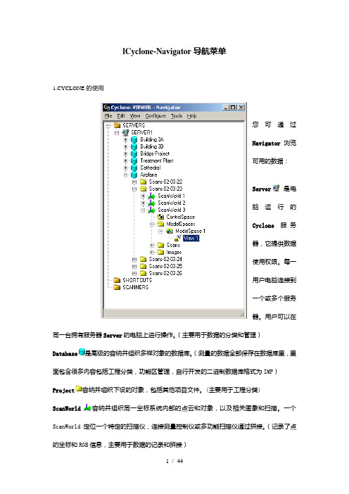
lCyclone-Navigator导航菜单1.CYCLONE的使用您可通过Navigator浏览可用的数据:Server是电脑运行的Cyclone服务器,它提供数据使用权限。
每一用户电脑连接到一个或多个服务器。
用户可以在同一台拥有服务器Server的电脑上进行操作。
(主要用于数据的分类和管理)Database是高级的容纳并组织多样对象的数据库。
(测量的数据全部保存在数据库里,里面包含很多内容包括工程分类,功能区管理,自行开发的二进制数据库格式为IMP)Project容纳并组织下设的对象,包括其他项目文件。
(主要用于工程分类) ScanWorld容纳并组织同一坐标系统内部的点云和对象,以及相关图象和扫描。
一个ScanWorld定位一个特定的扫描仪,连接测量控制仪或多功能扫描仪通过拼接。
(记录了点的坐标和RGB信息,主要用于数据的记录和拼接)ModelSpace容纳同一坐标系统内部的一组点云和3D对象,相当于一个3D模型。
(cyclone 里最重要的编辑区,几乎包括了所有的编辑操作,如点云的显示隐藏、旋转拉伸、点云切片、定义坐标系统,生成和插入模型、模型切片等等)ModelSpace View压缩设置(可视的和互动的),在空间模型浏览器中查看模型空间时使用。
一个给定的模型空间可能有多个模型空间视图,每个都有查看相同数据的不同方式。
(ModeSpace的视图,属于ModeSpace)Scan 相当于一次可以生成点云的扫描记录。
(相当于将点的X,Y,Z坐标以TXT文件的形式保存)Image是输入位图,或扫描的视频图象。
(记录扫描仪照的照片,扫描的全景为111张照片的拼合体,可将这些照片直接赋予点云,让点云更加直观)以下对象也可以在数据库中找到,但是不能通过Cyclone-VIEWER打开:Registration是连接不同ScanWorlds(每个都有不同的坐标系统)使其通向共同坐标系统的路径。
(也就是两站之间的拼接,可通过标靶和点云两种拼接方式)ControlSpace 是专门的模型空间, 容纳用于拼接的对象。
Cyclone快速入门(中文版)

bohe@
Page 3 of 59
Copyright © 2009 Leica Geosystems HDS, Inc. All Rights Reserved
更新: 2009 年 3 月 15 日
Leica HDS Training Manual
扫描仪位 置
ScanWorld 编
更新: 2009 年 3 月 15 日
Leica HDS Training Manual
Cyclone Quick Start
请在上述空白框中练习画出上述两站扫描的具有透视关系的视图。
在照片上做注 记
在每个规划图中标注出正确的标靶信息
z 另外一个替代性的做法是将标靶的位置在 Image Viewer 中标注出来,方法 是在图片上选取一点,然后使用如下明令: Tools | Annotations | Add/Edit Annotations,正如上述图片 3-4 SW2 中所显示的那样。
在本课程结束的时候,你将:
• 了解 Cyclone 工程的基本的工作流程 • 学习如何进行基本的建模操作,并且, • 在点和对象之间量测距离
本课程包含如下章节: 1 现场注释,规划图和扫描日志 2 使用 Cyclone 3 标靶介绍 4 将两个 ScanWorld 拼接到一起 5 点云统一化 6 切割点云 7 建模 8 创建一个平面(patch) 9 区域的生成 10 拟合圆柱体 11 创建管道 (Cylinders) 12 创建管道的连接部分(弯管) 13 测量物体表面间的距离 14 编辑模型 15 墙角/顶点的创建 16 面裁剪 17 用手柄工具操作模型对象 18 拷贝及移动操作
更新: 2009 年 3 月 15 日
Leica HDS Training Manual
cyclone培训笔记
Cyclone一Cycl one:Cyclone软件功能:数据获取-》点云拼接-》数据提取和分析-》数据输出1. cyclone 文件架构(1)SERVERS :存放工程文件,我们要进行操作的文件都放在该文件夹下SCANERS : 存放扫描文件SHORTCUTS: 不需要关注(2)继续在cyclone Navigator窗口中展开文件结构:ControlSpace:控制点和标靶的信息(只能看,不能编辑的)Modelspaces: 所有的编辑都在此模块Scans:标靶和扫描的一些信息Images:扫描时拍的照片。
2 cyclone中导入扫描的工程文件:(1)直接导入数据库文件(*.imp):I 打开cyclone,选中ADMIN-THINK(unshared),右击,单击“database”,出现如下对话框:2-1II 点击Add ,找到数据库文件,例如找到5.1Moudule 1 QuickStart.imp的位置,选中打开。
选择OK即可加入。
这样5.1Moudule 1 QuickStart在server文件夹下显示出来。
(2)导入的扫描文件中不含有*.Imp文件:I首先建立一个空的文件夹,例如20111018,在20111018下新建一个空的数据库文件,例如20111018.imp,步骤如下:a.打开cyclone-》选中ADMIN-THINK(unshared),右击,单击“database”,出现如下对话框:2-2B 单击Add.找到你想存放的目录,先新建一个文件夹,例如20111018,再双击打开该文件夹,在文件名栏输入你需要建立的数据库名,例如20111018,点击打开,选择OK。
这样一个空的工程文件20111018.imp建立了。
在cyclone的server下可以展开查看。
II导入扫描的数据:选中工程文件,右击选中import scanstation C10 data import scanstation C10 project,找到你需要导进来的扫描数据文件即可。
Cyclone5.8软件配准实习
Cyclone5.8软件配准实习报告及心得体会数字城市与三维建筑仿真实验室(1)、实习目的:掌握cyclone 软件的距离影像配准技术和操作过程。
(2)、实习要求:掌握连接点配准法、特征面配准法、公共点配准法、混合法、控制点配准法。
一、准备工作:1、距离影像文件:该文件来自Leica公司的各系列扫描仪,我们主要使用的是HDS3000和HDS6000型,HDS3000适用于较远距离扫描,扫描范围为150m,HDS6000适用于近距离扫描,扫描范围为1-25m。
他们生成的均是.ptx格式文件,该文件前两行是选中点云的行数和列数,接下来是一个4*3矩阵,下面是个4*4的变换矩阵,再下来就是点的三个坐标值和一个灰度值。
其中废点坐标表为(0 0 0 0.500000),整个文件可能被分成几块这样的部分。
2、按要求安装好的cyclone 软件。
拷贝几个文件到cyclone安装路径下:拷贝license.dat和sos_cyclone.exe到……\Cyclone\下;拷贝clwxap2.lic到….\ Cyclone \Bentley CloudWorx\AutoCAD 2004下,双击运行一下sos_cyclone.exe即可。
二、具体操作步骤:1.运行cyclone5.8 软件。
2.右键单击SERVERS打开Servers的ADD菜单,输入本地计算机名(Richard),点击add后创建完服务器,如下图:;同样步骤右击数据库Richard单击Database菜单的对话框里输入Database Name(Taihedian)和数据库存储路径;接着右击Taihedian导入数据菜单import….找到需导入的文件后选择Single,Merged Cloud项点击OK导入。
可连续导入几个数据。
3.控制点配准法的操作步骤:右击Taihedian菜单,新建配准窗口:Create->Registration后取名为“控制点配准”,双击该项目弹出配准操作窗口:Registration控制点配准。
测绘技术中的常用软件推荐与操作技巧

测绘技术中的常用软件推荐与操作技巧近年来,随着测绘技术的不断发展与更新,测绘人员需要借助各种软件工具来提高工作效率和准确度。
本文将对测绘技术中常用的软件进行推荐,并分享一些操作技巧,以帮助读者更好地应用这些软件。
一、三维测绘软件三维测绘软件在现代测绘工作中起到了重要的作用。
其中,SketchUp是一款功能强大且易于上手的三维建模软件,适用于不同规模的测绘项目。
通过SketchUp,测绘人员可以创建、编辑和分享各种三维模型,从而更好地展示和分析测绘数据。
在使用SketchUp时,有一些操作技巧可以提高效率。
首先,熟悉快捷键是必要的,比如使用“M”键进行移动操作、使用“R”键进行旋转操作等。
其次,合理利用组件和组织模型结构可以简化操作,比如将常用的图形元素定义为组件,方便重复使用和修改。
另外,如果需要进行精确的三维测绘,可以考虑使用AutoCAD Civil 3D软件。
该软件具有丰富的功能,可以进行道路、地形、管道等测绘项目的设计和分析。
在操作时,可以使用地块工具创建和管理地块,使用视图传感器来调整视图显示,以及使用管道网络设计和分析工具进行管道布置等。
二、地理信息系统(GIS)软件地理信息系统是现代测绘技术中不可或缺的一部分。
对于测绘人员来说,熟练掌握GIS软件的使用是必要的。
在众多GIS软件中,ArcGIS是一款功能强大的软件,广泛应用于测绘、地理空间分析和数据管理等领域。
在使用ArcGIS时,可以利用其强大的空间分析功能,例如缓冲区分析、叠加分析和网络分析等。
此外,熟练掌握ArcGIS的数据编辑和管理功能也十分重要。
比如,可以使用数据转换工具来处理不同格式的数据,使用编辑工具进行数据修改和更新,并使用数据库管理工具进行数据组织和查询。
此外,QGIS是一款开源的GIS软件,具有很好的兼容性和灵活性。
它提供了各种插件和扩展功能,可以满足不同测绘项目的需求。
在使用QGIS时,可以通过安装和使用各种插件来扩展功能,如QuickMapServices插件用于快速加载底图数据,Processing插件用于进行空间分析和处理。
三维激光扫描技术大比例尺数字测图中的应用

三维激光扫描技术大比例尺数字测图中的应用摘要:大比例尺地形图,它的位置精度高、地形表示详尽,是进行设计、规划、管理、建造过程中的基础信息。
目前,随着我国各大城市大比例尺地形图数据库的不断完善,重点解决大比例尺地形图工作效率低、成图周期长等问题迫在眉睫,使用航空摄影测量技术测绘小面积地形所花费的人力,物力成本较高,不能满足1∶500地形图的测量精度需求,而使用三维激光扫描技术能够实现影像资料的多角度采集,具有较高的分辨率。
关键词:三维激光扫描技术;大比例尺地形图;测绘方法三维激光扫描测量技术是继GPS技术以来测绘领域的又一次技术突破,它使测绘数据的获取与处理方法、测绘行业的服务水平等进入了新的发展阶段。
地面三维激光扫描技术是基于地面固定站的一种通过发射激光获取被测物体表面三维坐标、反射光强度等多种信息的非接触式主动测量技术。
其具有数据获取速度快,实时性强,数据密度大,数据精度高,安全性高等特点,这使得三维激光测量系统在很多工程应用中,具有常规测量技术所不具备的巨大优势。
基于三维激光扫描的地形测绘成图技术的应用,改变了传统测绘的作业流程,使相关外业测绘流程大大简化,外业工作时间大大缩短,外业人员的劳动强度大大降低,内业处理的自动化程度也显著提高。
目前,它主要应用于三维立体建模、变形监测、地形测绘、虚拟现实等方面。
1.三维激光技术原理三维激光扫描系统主要由三维激光扫描仪、计算机、电源供应系统、支架以及系统配套软件构成。
三维激光扫描仪作为三维激光扫描系统的主要组成部分,是由激光射器、接收器、时间计数器、马达控制可旋转的滤光镜、控制电路板、微电脑、CCD机以及软件等组成,是测绘领域继GPS技术之后的一次技术革命。
它突破了传统的单点测量方法,具有高效率、高精度的独特优势。
三维激光扫描技术能够提供扫描物体表面的三维点云数据,因此可以用于获取高精度高分辨率的数字地形模型。
利用激光测距的原理,通过记录被测物体表面大量的密集的点的三维坐标、反射率和纹理等信息,可快速复建出被测目标的三维模型及线、面、体等各种图件数据。
Leica Cyclone REGISTER 360 快速入门指南说明书

Leica GeosystemsQuickStart GuideProduct Leica Cyclone REGISTER 360 1.4.1Date 3 January 2018From HDS Software Product ManagementContentsIntroduction (2)Installation (3)Licensing Setup (4)Basic Workflow (6)Launch (7)Basic Configuration (7)General Settings (8)Link Settings (8)Cloud-to-Cloud options (8)General Registration Information (11)Import (11)Review and Optimize (19)Finalize (25)Report (27)Leica Geosystems AGHeinrich-Wild-StrasseCH-9435 HeerbruggSchweizIntroductionWelcome to Cyclone REGISTER 360. Bellow you will find a simple guide for getting started in the software.Cyclone REGISTER 360 is designed to bring speed, scale and simplicity to your digital reality workflows thanks to a new visual project interface and guided workflows. New and experienced users alike will appreciate that the registration process has been streamlined while maintaining the uncompromising quality you have come to expect of Leica Geosystems’ software solutions.Many users will require little to no assistance to complete their first project while some users who are completely new to the registration process may find it helpful to read this quick start guide in full.Please remember that every project will present its own challenges. This guide is not designed to address every possible scenario but rather to provide a framework which should be modified and amended based on project needs.If you require more advanced help, please review the resources in the assistant panel (discussed below) or contact Leica Geosystems’ expert support staff.Thank you for choosing Cyclone REGISTER 360.-The Leica Geosystems HDS Software Product Management TeamInstallationNOTE! You must have Administrative privileges on your computer to correctly installand license Cyclone REGISTER 360.1. Right-click on the Cyclone REGISTER 360 Setup File and select "run as administrator".2. Follow the directions in the InstallShield Wizard.3. When prompted, choose your Project Storage location.NOTE! The storage folder for Cyclone REGISTER 360 should NOT be the same folder as the JetStream Storage folder if JetStream is installed on the same computer.4. Complete the installation by selecting “Finish”.Licensing SetupLeica Cyclone REGISTER 360 will run for any user with a valid Cyclone REGISTER license with current CCP or CCP valid as late as September 1, 2017. (It will run non-concurrently to Cyclone REGISTER.) For users running Cyclone REGISTER 360 off its own license, please follow the below instructions to activated your license.NOTE! Leica Cyclone REGISTER 360 is only supported by the latest version of theLeica Client License Manager (CLM), version 1.6.2 or newer.NOTE! You must have an Internet connection to enable your license. If you do not,please review our “Leica Cyclone and CloudWorx Client License Management System” document that goes over setting up an E ntitlement ID (i.e., license) off-line.1. Once you have installed Cyclone, open the Client License Manager for Floating Licenses.2. Located here: Start Menu/All Programs/Leica Geosystems/Client License ManagerNOTE! Be sure to choose the Floating option (there are two CLMs and the NodelockedCLM will not activate your license)3. Choose the "Activate new licenses" option.4. Enter your Entitlement IDs (EID) in the open field. To enter multiple EIDs separate them with asemicolon ";"5. After you have entered your EID choose the "Check for Activateable licenses" link in the bottom rightof the page6. Once your licenses are activated you can start using Cyclone REGISTER 360.Basic WorkflowCyclone REGISTER 360 guides the user through the registration process. At the top of the software window you will see a workflow bar that includes four steps:(1) Import(2) Review and Optimize(3) Finalize(4) ReportThese will be the four major stages of your project. Below, we will walk you through a basic end-to-end workflow within Cyclone REGISTER 360. This is not intended to be exhaustive. You should reference the built-in assistant panel and help files for more detailed guidance. If you need more information about any tool, hover over the button and press F1 to be sent to the glossary or command index entry for the button within the helpfile.Launch1. To begin, launch Cyclone REGISTER 360.1.1. The software will open on the Project Explorer Window.2. Either open an existing project or click “Create New Project”2.1. Enter a project name and click “OK”Basic ConfigurationOnce the program is opened you can access the settings options from the title tool bar in the upper left of the program.General SettingsOnce you open the Settings dialog, the General tab will allow you to change your default units of length as well as set your preferred decimal precision.In this tab you also have the option to turn off the creation of Setup Archives during import, this setting enables the creation of archive files and is required for most publishing options.In this tab you can also turn off transition animations that occur when moving between setups or otherwise changing views.Link SettingsThe Links tab allows you to customize your error thresholds for Links. You can adjust what levels of error will be represented by your green/yellow/red link lines. By default, these will be set to 0.015 and 0.02 m respectively.Cloud-to-Cloud optionsOptions that control how Cloud-to-Cloud operates can be found in the setting menu.•Max Iterations:o This is how many times the programs will try to fit the clouds together before completing the alignment.•Search Radius:o This setting sets the search radius for matching surfaces•Max Point Density:o Will increase the density of the Cloud-to-Cloud points used in the process •Normal Threshold:o During Cloud-to-Cloud formation, the normal threshold is used to determine how valid the surfaces are. A higher value means that the surfaces do not need to be as valid. Theresult of a higher value would bemore surfaces, but potenally lower validity of thesurfaces created.ProjectsClick the Project & Storage icon in the upper left title bar to adjust storage folder locations and other project settings.In this view, you can see all the projects that you have stored in your Project storage.Here you can:■Manage your saved projects■Delete projects■Copy a project to another storage location using the Relocate option.■Archive or Import a Cyclone REGISTER 360 project (*.raf). To create a .raf file, select the project and click the Archive button.■Import a saved archive file. To do so, simply place the. raf file inside of your Project Storage directory and then click the Import button. Cyclone REGISTER 360 will then provide you a list of any archive it finds in that location that can be added to your active Projects.StorageThe Storage tab allows you to configure multiple Project Storage locations. You can use this feature to create and toggle between datasets on multiple drives. For best results, use internal SSD drives and create separate folders for Storage and Archive.General Registration Information■Cyclone REGISTER 360 requires 3 matching targets between setups to form a target link.■Cloud to Cloud links can be used to join setups with less than 3 matching targets.■Setups included in separate Sitemaps in the Import area will be registered into separate bundles.■The maximum amount of auto-detected/shown links is 50. This applies to links found after Visual Alignment, Split View, and shown suggested links.■You must have at least one Sitemap which has all setups in one bundle to proceed to the Finalize area.■The bundle must be optimized successfully (no dotted Link lines) to proceed to the Finalize area.■The minimum screen resolution supported is 1280x800.Import3. You will now find yourself in the Import stage. You will notice on the left that there are three ways tobring data into Cyclone REGISTER 360.3.1. Cyclone REGISTER 360 can accept the following types of scan, image and text files:File Types Supported Formats Binary Point Clouds .e57.ptgControl File .txt containing:Point numberNorthingEastingElevationCommentImagery .bmp.jpeg.pngFARO TLS data .fls.fpr.fwsFARO RawLeica HDS scanner data BLK360 (direct via WiFi or .blk files from theBLK360 Data Manager utility)C-SeriesP-SereisText .ptxZ+F .zfc.zfs.zfprj3.2. Different file types do not need to be added separately; they can all be added and importedtogether.3.3. “Drag files here” allows you to drag-and-drop individual files, or a folder containing files, into thesoftware.3.4. “Browse Files” will launch a Windows File Exploer window through which you can navigate to thefiles to be imported.3.5. “Import BLK360” will launch a new Cyclone REGISTER 360 window that will allow you to connectto a local BLK360 Imaging Scanner and select individual files to import.3.5.1. Connent your computer’s wifi to the BLK360 using the windlows wireless connection(Windows 10 is used in this example). The wireless password is located on the inside of the battery door of the BLK360 scanner.3.5.2. C lick “Find & Connect Device"3.5.2.1. Once connected a list of scans is shown along with the Battery level, Serial numberof the scanner, firmware version, memory used and Capture settings.The scanner must have at least 20% power to enable the Download button.3.5.2.2. Select the scans to import by marking the check boxes next to each setup. Selectingscans in the BLK360 import dialog will check the scans for import in the Cyclone REGISTER 360 import area though all scans will be visible within the import area. Click "Download" when you have identified the scans you wish to work with.3.5.2.3. Capture settings can be changed in this dialog. Use the pull downs to select scandensity (high, medium, low), image quality (LDR or HDR) and Image exposue (EV-5 to +5).3.5.2.4. The Add to Project button will always display all scans witin the CycloneREGISTER 360 import area, however only scans which were selected within the import dialogue will be queued for import. The image below shows the three scans selected for import above checked for import.3.5.2.5. You may also delete scans from your BLK360 from within this window. Select thescans by checking the boxes to the left of the scans and the click the Delete button.Once scans are deleted, they are permanently removed from the device so the user may wish to download them locally via the BLK360 Data Manager as a backup before any deletion from the machine.4. Once you have added your data via one of the methods noted above, you will also notice on the rightthat there are three options for how to register the data you are bringing in which can be used for any of the above import types.4.1. “Auto Target” should be used when Black and White targets are present within the data set.Cyclone REGISTER 360 will automatically search for these targets and register the setups based on those shared targets. Targets do not need to be picked, labelled or matched. Cyclone does it all automatically.4.2. “Auto Cloud” should be used when importing unregistered data that does not contain targets. Thissetting will conduct a preliminary cloud-to-cloud alignment and register the setups based on shared geometry between scans. You do not need to pick this option. Cyclone REGISTER 360 does it all automatically.4.2.1. “SmartAlign” is a tool that will aid the Auto-Cloud search by lowering the number of links tosearch by only searching the links specified by the user. All setups not identified by the userwill be compared to all other setups. Once SmartAlign is selected, links can be createdbetween setups by time, distance, or by manually dragging one setup to another.Note! The SmartAlign option will not be enabled unless a background image is in use(blank is fine) and setups have been dragged into the Sitemap area.4.3. “Pre-Registered” should be used for data that has already been registered in another application.This setting will maintain the alignment and transformations present within that data set and generate the link objects unique to Cyclone REGISTER 360.4.4. If no options are checked, Cyclone REGISTER 360 will import the files but will not attempt to formany links.5. The last section of the import stage is the map tool. This map can be used to acquire a satellite imageto serve as a sitemap for the project. (Optional).5.1. You must be connected to the internet to use the map.5.2.You can scroll to a known location or enter a sreet address, city name, or ZIP code. You must thenclick “Lookup” to search the map.5.3. Once you are satisfied with the positioning of the image on screen, click “Get Image” to save thescreen and automatically set it as your sitemap background image.5.4. If you wish to use your own image as a sitemap, you can add that image via the “Drag files here”or “Browse Files” options.6. Once you are satisfied with the data that has been added and made the appropriate selectionsregarding registration options, c lick the large, red “Perform Import” button in the lower right corner of the screen.Review and Optimize7. Once the import is complete, the user will be placed within the Review and Optimize stage. Here,they can QA and refine the registration and produce assets to include within the final Registration Report.7.1. On the left-hand side, you will see a complete directory of all data within the project, clusteredunder three tabs: “Project” which contains sitemaps, bundles, setups, and links, “Assets” which includes all image assets both imported and those created via the “Capture Screen” button, and “Controls” which includes any imported .txt files cont aining survey control information.7.2. The user can access the properties for an object by selecting that object in the project panel andviewing the “Properties” panel on the right-hand side of the screen.7.3. The “Properties” panel can be viewed with “Advanced Mode” On or Off depending on whether theuser wishes to see a more graphical or more tabular summary of their data. The Advanced mode also offers additional link options.7.4. Next to the “Properties” panel, the “Assistant” panel contains specif ic advice and informationpertaining to each stage of the registration.7.5. Within the Review and Optimize stage, the user may refine their registration through a variety oftools.7.5.1. T he user can delete setups and links and re-form them.7.5.2. T he user may also refit targets at this stage to improve the registration.7.5.3. T he user can set a unique User Coordinate System to orient their project for better viewing.7.6. The user may view their project either as a “Sitemap” (2D, top-down) view, or as 3D cloud byhovering over the icon in the lower right-hand corner of the workspace and selecting the appropriate viewing option.7.6.1. T he user should use the “TruSlicer” view to QA their regsiration. The point clouds from eachsetup will be colored differently. A good alignment will show a thorough intermixing of colored points and matching geometry in areas of overlap. The user can control the thickness and location of the slice via the sliders at the top left of the workspace.7.7. Depending on the user’s selection, a “Navigation” bar may appear in the top left of the workspaceor an “Action Bar” at the bottom that will enable different tools that are only accessible with the user’s present selection.NavigationBarAction Bar7.8. At any point, the user may access their “Settings” by clicking on the gear icon at the very top leftof the screen to change units and set the error threshold for green, yellow and red links.7.9. At any point, the user may click the “Capture Screen” button to save an asset which can ch osento include in their final Registration Report. These assets will appear in the “Asset” tab in the project panel at left.7.10. T o increase working space, the user may collapse either or both side panels by clicking the arrowat the sides of the panel.Finalize8. Once the user is satisfied with their registration, they may move on to the Finalize stage by clickingthe “Finalize” bar at the top of the screen.8.1. Within the “Finalize” stage the user can make final adjustments to the presentation of their projectby turning On or Off the point cloud, setups, links, sitemap, and setup labels.8.2. When the user is satisfied with the presentation of the image, they may click “Accept” in the ActionBar. This will freeze the image on screen to serve as the Registration Report cover image.8.3. T hen click the large, red “Accept” button in the Properties panel to advance to the Report stage.Report9. Within the Report stage, the user will have many customization options.9.1. They may enter their name under the “Certified by” line as well as their Title or Position, CompanyName, and URL as well as a Heading for the Regsitration Report. To update the Report with this information, click “Update Report.”9.2. The user may also select what they want to include within their report by checking or uncheckingthe boxes for the sitemap image (the large image captured in the Finalize stage), a logo (whichthey can add via Drag-and-Drop next to the check boxes, the Links Table, Targets Table (histogram of errors for links displayed as a matrix of setups), and Assets. To select or deselect individual assets for inclusion, the user may click “Configure.”Check thedesiredoptions here.9.3. Lastly, the user has many publishing options for how they wish to share their project. TheRegistration Report will always be created as a .pdf, however the user can choose to optionally publish their project to TruView Local or TruView Enterprise if they have a Cyclone TruView PUBLISHER or Cyclone PUBLISHER Pro License, TruView Cloud if they have a TruView Cloud subscription, JetStream Local or JetStream Enterperise if they have a Cyclone JetStream PUBLISHER or Cyclone PUBLISHER Pro License, or as an.e57 file.**Creates *.jsv files for viewing point clouds and imageryin JetStream ViewerNo additional license required E57 compatible products of users’ choice E57No additional license required PTX compatible products of users’ choice PTXNo additional license required PTS compatible products of users’ choice PTSNo additional license required PTG compatible products of users’ choice PTG9.4. The user should select all of the publication outputs they wish to produce from this list and thenclick the large, red “Publish” button in the properties panel. This will allow for single, batch publishing of all your selected outputs.9.5. All of the outputs will be created and saved to the location designated by the user.。
三维激光扫描结合BIM技术在建筑三维模型构建中的应用

三维激光扫描结合BIM技术在建筑三维模型构建中的应用近年来工程信息化不断发展,3D 建筑建模技术越来越成熟。
尤其是随着建筑信息模型( BIM)技术的提出,3D 建筑模型中又能够被赋予诸如进度、投资等信息,形成4D 乃至5D 的BIM模型。
换言之,BIM 技术的推广,使得建筑图纸更加直观,具有了生命。
建筑信息模型(Building Information Modeling,BIM)是以建筑工程项目的各项相关信息数据作为模型的基础,进行建筑模型的建立,通过数字信息仿真模拟建筑物所具有的真实信息。
近年来,BIM在建筑相关领域应用迅速,在未来有望全面改变建筑设计、施工、检测等诸多方面的模式。
一、扫描测量技术概况:随着信息技术和测量技术的不断发展,目前开始逐步应用于工程领域的主要有2 种扫描方式,即三维激光扫描和全景扫描。
1.1 三维激光扫描三维激光扫描技术又称为实景复制技术,是测绘领域继GPS 技术之后的又一次技术革命。
它突破了传统的单点测量方法,具有高效率、高精度的独特优势。
三维激光扫描技术能够提供扫描物体表面的三维点云数据,因此可以用于获取高精度高分辨率的数字模型。
它通过高速激光扫描测量的方法,大面积、高分辨率、快速地获取被测对象表面的三维坐标数据。
1.2 全景扫描全景扫描是通过用成像设备( 目前通常采用高像素数码相机) 采集一系列图像序列,再经过软件对图像进行匹配拼接,最后融合成一张显示全部图像内容的“超级图像”,可以视这个“超级图像”为全景。
“超级图像”含测量数据及坐标数据,可直接与BIM 模型或其他同视角“超级图像”进行对比,了解工程实际效果与设计的差异。
1.3 两种扫描技术对比:由表1可以看出,两种扫描技术各自具有鲜明的特点,主要如下:表1 三维激光扫描与全景扫描方式对比Contrast between 3D laser scanningand panoramic scanning1.3.1 三维激光扫描的优势主要在其扫描精度以及与BIM 模型的便捷比对。
三维声呐在水下沉船姿态探测中的应用
三维声呐在水下沉船姿态探测中的应用发表时间:2020-12-03T12:43:33.097Z 来源:《科学与技术》2020年21期作者:杨文宙徐俊洲[导读] 声呐技术伴随着失事沉船扫测而发展起来,目前已经成为认识杨文宙1 徐俊洲2交通运输部东海航海保障中心上海海事测绘中心上海市200082摘要:声呐技术伴随着失事沉船扫测而发展起来,目前已经成为认识、开发和利用海洋的重要手段。
特别是近20年来声呐技术不断进步,已经能够在非接触测量模式下快速获取水下目标物的尺寸及相对于声呐的方位信息,在水下沉船姿态探测方面也逐渐开始应用。
通过研究采用多波束测深仪与三维扫描声呐相结合的技术方法,建立了水下沉船的三维点云模型,既能为沉船姿态测量和损伤评价提供支持,也能为打捞方案设计提供基础数据,对提高打捞成功率具有重要作用。
关键词:沉船姿态探测;多波束测深;三维扫描声呐船舶大型化是当前海洋运输的发展趋势,所以提升大吨位沉船整体打捞能力具有极其重要的意义。
为了保证沉船能够被高效快速的打捞,沉船姿态探测与损伤观测是制定打捞方案的重要前提。
因此利用现代化测量手段快速准确地测定沉船姿态及损伤程度是保证打捞成功率的重要数据保障,也是当前救捞系统面临的迫切任务。
一、水下沉船的三维点云模型首先使用多波束测深仪扫测沉船的精细轮廓和周边地形,使用的多波束为了减小误差、提高精度,将姿态传感器与多波束探头尽量接近,并将RTK GPS天线置于固定杆顶部;考虑到沉船底部和侧面不容易扫描到,将多波束探头向外侧倾斜30°安装。
数据采集采用无动力的驳船,在沉船四周抛好锚,通过绞锚在沉船上方缓慢移动。
测量范围为200 m×60 m,使用三维扫描声呐对沉船侧面、底面进行扫测,目的是精确测量沉船的局部细节,是对多波束测量的补充。
为了使三维扫描声呐能够固定在海底稳定工作,制作了带配重的专用支架,并在支架上安装水下定位信标。
三维扫描声呐连接调试正常后,将其吊放入水,由定位信标引导到设计位置。
徕卡三维激光扫描Leica Cyclone 8.0.0.3382

DepoCAM v5.0.19-ISO 1CD (為一套傻瓜級的3D加工軟體 )
Numeric Vision产品:
Type3 Type Edit 2003 v5.3.0.0-ISO 1CD (雕刻软件,商业多语言版本)
Type3 v4.6-ISO 1CD (雕刻软件,商业多语言版本,包含简体中文)
徕卡三维激光扫描Leica Cyclone 8.0.0.3382
Leica.Cyclone.v7.4.1 & Plugins.Win64 1DVD
Leica CloudWorx and ForensicMAP plugins collection 1CD
Leica.Cyclone.II.Topo.v2.0.188.Win32 1CD
+
+请 按 Clrt+F 查找, 输入 具体 关键字 查询(不要全部输入)
+++++++++++++++++++++++++++++++++++++++++++++++++++++++++++++++++
NC Graphics (Cambridge) Ltd产品:
leica莱卡LGO软件使用简易手册

目录前言 (1)一、软件安装 (2)二、数据处理 (6)三、数据输出保存 (8)四、定义输出模板文件 (9)前言非常感谢并祝贺您购买徕卡TPS1200系列仪器。
为了让徕卡TPS1200系列仪器在您的工作中充分发挥其应有的作用,我们为您提供这套功能完善的LGO数据处理软件,本手册将向您详细叙述该软件的使用方法。
时间仓促,难免有疏漏之处,欢迎您对本手册的不足之处批评指正,提出修改意见或建议,我们将随时改正,同时,我们非常欢迎您将您使用该软件的心得和经验告诉我们,我们将不胜感激并虚心学习。
我们将随时准备为您服务。
我们的联系方式:电话:传真:电子信箱:2004年7月一、软件安装1、打开安装盘,选择SETUP2、进入安装向导3、在此界面,点击下一步4、在此界面,点击下一步5、在此界面,点击是6、在此界面,点击下一步7、在此界面,选择LEICA Geo Office Terrestrial(LEICA Geo Office Combined是GPS用),点击下一步8、选择安装路径,建议用缺省路径,点击下一步:9、在此界面,点击下一步:10、在此界面,点击下一步:11、安装开始:12、安装完毕:13、安装完毕后,会在桌面上出现以下图标:请注意:如果安装过程中提示Dongle路径不对,请打开安装盘中的Dongle文件夹,选择DRIVER541后继续即可。
二、数据处理1、在桌面上双击LEICA Geo Office Terrestrial图标,程序启动后,进行如下操作:管理工具条→项目→(点击右键)新建:2、输入项目名称,选择存储路径,点击确定:此时项目为没有内容的空项目。
3、在工具栏里点击输入原始数据:4、在查看处选择数据文件所在位置,在文件类型处选择system1200原始数据或相对应的数据格式(TPS1100系列选择GSI格式,当有多个数据文件时,如果不选择包含子文件夹,则只输入选中数据文件,如果选择包含子文件夹,则输入全部数据文件),点击输入:5、点击分配,将数据导入空项目中,然后点击关闭:三、数据输出保存1、点击输出菜单或工具栏中的ASCII文件输出:2、a、选择要输出的数据格式,输出保存:点击设置,可设置内容:b、要输出自定义格式,请在保存类型行中选择定制ASCII文件,然后再点击设置,在格式化模板处点击,选择自定义模板文件,保存:四、定义输出模板文件在内业处理时,我们可以根据需要,编辑我们需要的数据输出格式,也就是说,只要我们知道了所用成图软件的数据格式,我们就可以自己动手编辑一个适用于该软件的数据输出格式,这可以方便地实现软件与仪器之间数据的对接。
两三年下来集合所有的软件信息

Shell.Shepherd.v2.0?1CD?风险评估
Shell.FRED.v5.0?1CD火、释放、爆炸、分散风险的后果建模软件包
TNO.Effects.v9.0.16.8022??
风险评估TNO.Riskcurves.v9.0.18.8069?
宇柏林_治具
Vensim.6.0b.Portable 1CD
Accelrys.Pipline.Pilot.v7.5研发业务智能平台
Delcam?PowerSHAPE?2014?R2?SP5
DNV?Phast?v6.7-ISO?1DVD
LDRA.Testbed.v7.2-ISO?1CD
华塑CAE7.0
PCA?COL?v2.0?1CD
PCA.spMats.v7.51?1CD
Aquaveo?Groundwater?Modeling?System(GMS)?v10.0.5?Premium?Win64?1C
SofTech.Cadra.v2006plus.WiN32-oDDiTy
Etap.PowerStation.v7.5-ISO?1DVD
Jmag Designer 12 Win64
Lantek.v27
JMatPro v3
Gemcom Whittle 4.4
Sigrity.SpeedXP.Suite.V9
LMS Raynoise v3.0
Catt-Acoustic v8.0(室内声场模拟软体)
Flow-3D v10
Landcad Eagle Point (园林设计软件
AutoTURN v6.0
建筑物立体点云数据处理的方法与软件选择

建筑物立体点云数据处理的方法与软件选择建筑物立体点云数据处理是近年来在建筑行业领域备受关注的一个重要课题。
随着激光扫描仪和三维摄影技术的发展,获取建筑物的三维点云数据变得越来越容易。
然而,处理和分析这些大规模的点云数据是一项具有挑战性的任务。
首先,让我们来了解一下什么是点云数据。
点云是由大量离散的三维点构成的数据集合,这些点可以表示物体的形状、尺寸和表面特征。
在建筑领域,点云数据可以用于建筑物的建模、变形分析、结构检测等方面。
在处理建筑物立体点云数据时,有几种常用的方法。
其中一种方法是基于几何形状的分析。
通过对点云数据进行滤波、分割和曲面重建,可以提取出建筑物中的各个组成部分,比如墙面、楼梯、窗户等。
这种方法能够获得较为精确的建筑物几何形状,但在处理大规模点云数据时,计算复杂度较高。
另一种方法是基于特征分析的点云处理。
这种方法通过提取点云数据中的特征,如曲率、法线方向等,来实现建筑物的分析与识别。
通过这种方法,可以较快速地获得建筑物的结构信息,对于快速检测建筑物的异常情况和变形具有一定的优势。
在选择建筑物立体点云数据处理软件时,需要考虑以下几个因素。
首先是软件的功能和可扩展性。
优秀的点云处理软件应该具备滤波、分割、配准、建模等基本功能,并能够适应不同规模和复杂度的点云数据。
其次是软件的易用性和用户界面设计。
因为建筑领域的专业人士可能缺乏计算机编程方面的知识,因此软件的操作界面应简洁、直观,并提供友好的用户交互方式。
此外,软件的计算性能和效率也是一个重要考虑因素。
大规模点云数据处理需要消耗大量的计算资源,因此软件的计算效率应高,能够充分利用多核处理器的优势。
最后,软件的技术支持和后续更新也是选择的关键。
建筑物点云数据处理是一个持续发展的领域,软件的技术支持和后续更新能够为用户提供更好的使用体验和功能更新。
目前市场上有许多优秀的建筑物立体点云数据处理软件可供选择。
例如,AutoCAD Civil 3D是一款功能丰富的建筑物点云处理软件,它具备强大的点云数据导入、滤波、分割、配准等功能,并且可以与其他CAD软件进行无缝集成。
Cyclone快速入门(中文版)

扫描 编号
包含标靶
扫描区域描述
A
SW1
1
S1, S2, S3, Tank room- 从左侧
S4
扫描
Cyclone Quick Start
注解
ModelSpace View 名称
SW1-A 从左边的 视图
B
SW2
1
S1, S2, S3, Tank room- 从右侧
S4
扫描
SW2-B 从右边的 视图
个点。
z 点击空格键或按 ESC 来释放选择的点云。
点的数量可通过如下操作调整:Preferences 窗口 – Edit | Preferences | ModelSpace 标签,然后选择 Viewer: Point Thickness, 和 Viewer: Point Thickness (Highlighted).
bohe@
Page 5 of 59
Copyright © 2009 Leica Geosystems HDS, Inc. All Rights Reserved
更新: 2009 年 3 月 15 日
Hale Waihona Puke Leica HDS Training Manual
Cyclone Quick Start
Leica HDS Training Manual
Cyclone Quick Start
Leica Geosystems
HDS
培 训 手 册
Cyclone 快速入门
bohe@; bin.li@
Page 1 of 59
Copyright © 2009 Leica Geosystems HDS, Inc. All Rights Reserved
- 1、下载文档前请自行甄别文档内容的完整性,平台不提供额外的编辑、内容补充、找答案等附加服务。
- 2、"仅部分预览"的文档,不可在线预览部分如存在完整性等问题,可反馈申请退款(可完整预览的文档不适用该条件!)。
- 3、如文档侵犯您的权益,请联系客服反馈,我们会尽快为您处理(人工客服工作时间:9:00-18:30)。
Leica Cyclone 软件是三维激光扫描领域内的主流软件系统,该软件是HDS扫描仪的配套软件。
用户使用该软件可以高效率地控制徕卡测量系统的多种HDS 扫描仪。
使用该软件用户可在工程测量、制图、及各种改建工程中处理海量点云数据。
Leica Cyclone 三维数据处理软件的主要特点
Cyclone-SCAN
Cyclone-REGISTER
Cyclone-MODEL
Cyclone-SURVEY
Cyclone CloudWorx
1.输出二维或三维图,线画图,点云图,三维模型,ASCII坐标数据等
2.可控制LEICA扫描仪完成点云数据采集
3.自动扫描测量标靶
4.设置照相机曝光和分辨率
5.数据采集批处理功能
6.依据标靶或/和点云实现点云拼接
7.数据分块处理和管理功能
8.海量数据管理(可支持10亿点以上的数据管理)
9.根据点云自动生成平面、曲面、圆柱、弯管、法兰…
10.实现三维管道设计
11.自动构网和生成等高线
12,依据切片厚度生成点云切面
13.用CloudWorx模块可在AutoCAD或MicroStation中处理点云数据
14.可以输出DXF,PTX,PTS,TXT等多种数据格式
15.新的正射影像功能
以前的Cyclone软件的MODEL模块具有材质贴图功能,用户可以用外部数码相机拍摄的照片来渲染点云。
现在,该项功能得到进一步的扩充,在渲染点云的同时用户可以输出正射影像。
这样一来,CAD用户可以在纠正后的影像上精确跟踪得到高精度的二维线画图。
摄影测量系统中的漫长而复杂的工作流程,现在无缝地整合到了Cyclone强大的三维点云系统之中。
细节丰富的古建筑正立面图、工厂改建工程中复杂的机器图形,以及传统航空摄影测量得到的地形图都可以在Cyclone中结合点云来获得。
新的放样功能
Cyclone SCAN5.8是市场上专为激光扫描仪提供放样功能的软件模块。
截止目前,激光扫描仪仅应用于各种测绘制图工程中,并未在工程放样中得到应用。
现在,在新版本的支持下,具有双轴补偿器的HDS扫描仪将可以应用于简单的工程放样。
使用者先将放样点的坐标上传到控制扫描仪的笔记本电脑中,然后扫描位于对中杆上的标靶。
此时,Cyclone SCAN 5.8会显示相关的放样信息——据此信息,作业人员按适当的方向和距离挪动对中杆,直到最终放样出该点。
该工具接收标准的测量点号记录,可以依次放样出多个点位。
这一新增工具的优势在于,可以将三维激光扫描仪应用于制图和放样同步进行的工程。
在放样少量点的测站上,扫描仪可以替代全站仪或GNSS/GPS进行放样,所以,该功能减少了工程项目对全站仪或GNSS/GPS的需求。
就放样的工作效率而言,扫描仪+标靶并不及全站仪+棱镜或GNSS/GPS的工作效率。
因此该项功能并非要取代全站仪或GPS来应用于大量点的放样工程。
但是,当仅需放样少量点或手边没有其他仪器时,它却不失为一种方便、省时的工具。
扩展了软件的协同工作的功能
为了支持HDS激光扫描仪硬件和软件产品日益广泛的应用,Cyclone 5.8扩展了系统之间的协同工作能力。
首先,广大面向AutoCAD应用的徕卡CloudWorx 用户现在可以通过免费的Cyclone VIEWER模块处理其它仪器(如航空雷达、非徕卡测量系统的扫描仪)的ASCII, PTS 和PTX等格式的数据。
在Cyclone
5.8之前的版本,用户需要购买Cyclone 软件中的相关软件来进行数据转换。
其次,Cyclone 5.8目前可以通过一种新的PTZ数据格式,将HDS的数据导出到LFM软件中。
正射影像图生成、放样以及兼容性扩展了徕卡Cyclone5.8软件的更多拓展空间
需要说明的是,在该次软件发布之前,徕卡测量系统已经发布了Cyclone5.8的一些新功能,包括:HDS6000扫描仪硬件控制模块、徕卡TruView以及Cyclone PUBLISHER 软件模块。
与本次发布的正射影象和放样模块一起,所有这些新增模块扩展和加强了软件的互用性。
新发布的Cyclone 5.8软件代表了高清晰测量领域主流软件的技术发展方向。
“鉴于Cyclone5.8新发布的先进功能,无论是生产能力还是多用途性方面,该版软件把三维激光扫描市场提升到了一个崭新的水平上来。
同时,对于那些期望进入高清晰测量领域(三维激光扫描领域)的组织或个人,该款软件减小了他们学习激光扫描技术的难度,降低了他们进入激光扫描行业的门槛。
借助我们的激光扫描工具集合,徕卡测量系统为您提供行业内最完整的解决方案。
”徕卡测量系统扫描业务副总裁Ken Mooyman先生说。
“新增的正射影像和放样功能提升了徕卡测量系统做为行业领导的地位。
新的HDS6000型相位激光扫描仪的结构紧凑,配以免费易用的浏览量测软件,HDS的工程应用获得了更广阔的市场空间。
”
Cyclone5.8软件将正射影像和数据量巨大的点云数据整合到了CAD环境中,用户可以此来生产各种改建图纸和地形图。
(注:文档可能无法思考全面,请浏览后下载,供参考。
可复制、编制,期待你的好评与关注)。
