机房空调艾默生安装维护手册
艾默生电源维护手册(修改版)
1维护牵手行 共织动力网中国移动通信山东分公司艾默生开关电源维护速成宝典艾默生公司济南客户服务中心二零零五年九月2序 言中国移动通信责任有限公司山东分公司是艾默生网络能源有限公司极其重要客户和伙伴。
目前,山东移动网上运行的艾默生智能开关电源(包括前华为开关电源)共2800余套,其中,电源大部分型号集中分布如下:八期建设的由NP9801监控单元构成的PS48300-2/50,PS48450-2/50系统;九期建设的由PSM-A 构成的PS48400-2/50,PS48600-2/50系统;十期建设的PS48400-2B/50系统;十一期建设的的PS48400-2C/50系统;同时十二期正在建设中的基站电源也集中在由M500F 监控单元所组成的PS48400-3/2900和PS48600-3/2900系统。
此外,在早期基站中,还有部分由PSM-15组成的PS48100/25,PS48300/25,PS48120/20,PS48240/20系统。
以上型号的电源占到了目前总量的90%以上。
为了进一步加强山东省移动公司基层的维护技术力量,帮助贵公司提升网络质量,打造GSM 精品网络,共同提高移动公司市场竞争力,艾默生济南客户服务中心特组织精兵强将,以移动公司相对集中设备型号,编写了该维护手册。
本手册不仅包含了日常维护中80%以上的设备运行问题,同时,还介绍了电源日常保养、巡检和电源安装工程的内容和规范。
我们期待此手册能达到我们预期的目的,希望我们的服务能为贵公司在严峻的竞争中尽绵薄之力。
由于笔者水平有限,也恳请贵公司领导和同行们多指教!31`第一篇:由NP9801构成系统日常维护指南(PS48300-2/50,PS48450-2/50)...................................................................................................................................... 1问一:由NP9801监控单元组成系统的结构与配置情况? ............................................... 1 问二:如果机房无三相电或有缺相时,电源的交流引入线如何连接? ......................... 1 问三:整流模块前面板拨码开关是什么含义,如何设置? ............................................. 2 问四:模块地址如何设置? ................................................................................................. 2 问五:在更换该系统的整流模块时,有何注意事项,正确步骤? ................................. 2 问六:有时在开启模块输入空开后,模块打火或者后面开始冒烟?何故?如何处理? ................................................................................................................................................ 3 问七:当系统中其中一个模块无输出电流时,如何判断其好坏? ................................. 3 问八:模块间是否均流的判断标准是什么?当整流模块不均流时,如何调节? ......... 3 问九:为什么有时拆除一台整流模块,其他整流模块同时出现通信中断故障? ......... 4 问十:系统中单个模块通信中断,通常由那些因素造成,如何处理? ......................... 4 问十一:监控单元密码是多少?分别有什么用? ............................................................. 4 问十二:对于NP9801监控单元组成的系统,如何正确进行系统配置? ....................... 4 问十三:监控单元有集中复位方式? ................................................................................. 5 问十四:监控模块内需要设置的电池参数有哪些? ......................................................... 5 问十五:对于电池组数的设置,如果系统只有一组电池应该如何连接,监控模块如何设置?......................................................................................................................................... 5 问十六:忘记用户级密码如何处理? ................................................................................. 5 问十七:防雷器部分如何维护? ......................................................................................... 5 附录:NP9801监控单元内目录结构如下: ........................................................................ 6 第二篇:由PSM-A 构成系统维护指南(含PS48400-2/50,PS48600-2/50) ... 7问一:使用PSM-A 监控单元的型号有哪些? ..................................................................... 7 问二:交流接触器不吸合? ................................................................................................. 7 问三:交流接触器频繁跳动(吸合后随即断开)? ......................................................... 7 问四:交流防雷器故障告警? ............................................................................................. 7 问五:交直流通信异常? ..................................................................................................... 7 问六:交流电压正常,模块工作正常,但是负载不能够工作? ..................................... 8 问七:监控单元显示直流电流或电池电流与模块输出显示电流偏差很大? ................. 8 问八:负载熔丝断误告警? ................................................................................................. 8 问九:模块通信中断故障如何判断?如何处理? ............................................................. 8 问十:模块有输出电压,但没有输出电流? ..................................................................... 9 问十一:监控单元没有显示? ............................................................................................. 9 问十二:更换监控单元需要设置的数据? ......................................................................... 9 第三篇:PS48400-2B/50,PS48400-2C/50电源系统维护指南......................... 11问一:通常艾默生开关电源都由哪几部分组成? ......................................................... 11 问二:PS48400-2B/50系统交流配电部分由哪些部件组成? ...................................... 11 问三:移动十一期基站使用的PS48400-2C/50系统与十期基站的PS48400-2B/50系统有2何区别?在维护的时候有什么区别? ............................................................................. 11 问四:有哪些常见的交、直流保护参数?参照值为多大? ......................................... 11 问五:PS48400-2B/50系统的工作原理? ...................................................................... 12 问六:直流配电的基本特点? ......................................................................................... 12 问七:如果交流接触器不吸和,如何判断交流接触器的好坏?如何采取应急措施? . 13问八:常见的模块故障有哪些,可能原因分析。
艾默生SDC空调使用说明手册

艾默生SDC空调使用说明手册一、设备用途向地下吹风的打空调,用于机房温湿度调节。
二、接口类型通讯接口采用RS485/232方式。
信息传输方式为异步方式,起始位1位,数据位8位,停止位1位,无校验。
数据传输速率为1200、2400、4800、9600和19200bps可以设置。
三、通信参数设置1、控制器SDC系列空调的控制器为PACC控制器,采用240*128点阵蓝色背光液晶显示屏显示,用户界面操作简单。
多级密码保护,能有效防止非法操作。
控制器具有掉电自恢复功能。
通过菜单操作可以准确了解各主要部件运行时间。
专家级故障诊断系统,可以自动显示当前故障内容,方便维护人员进行设备维护。
可存储200多条历史事件记录,配置RS485接口,通信协议采用信息产业部标准通信协议,控制器面包那如图1所示图1 控制器面板2、操作键功能说明控制器有5个操作键,分别是开/关键、退出键、上移键、下移键和回车键。
功能见下表:表1 操作键功能说明33.1 主界面图2 主界面界面上包含三类机组工作图标,分别是动画运行状态图标、锁定状态图标和开关机主备状态图标,这些图标告知操作员机组正在何种运行模式下运行。
图标及其含义如图3所示。
图3 图标含义3.2 密码界面在主界面下按回车键,显示输入密码界面,如图4所示。
输入正确密码确认后即可进入主菜单界面。
图4 密码输入界面进入菜单界面的密码分3个等级,需要密码打开的菜单在它的标题后标有菜单级别[1]、[2]、[3],以表示所需密码的级别。
各种密码等级的使用者、初始密码、允许进入的菜单等级见图5。
图5 密码等级注意:操作者输入不同等级的密码,可获得相应等级的密码权限。
操作者只等修改对应密码权限的菜单项,否则只能浏览菜单内容。
3.3 通讯设置在系统设置界面图6中,课选择进入到通讯设置菜单,如图7所示,通讯设置子菜单包括:通讯协议、通讯地址和波特率。
波特率可选的通信速率包括:1200bps、2400bps、4800bps、9600bps和19200bps。
艾默生机房精密空调的重点日常维护

艾默生机房精密空调的重点日常维护艾默生机房精密空调的重点日常维护时间:2012-06-20 17:02来源:未知作者:zx 点击:1563次一、精密空调的结构及工作原理精密空调主要由压缩机、冷凝器、膨胀阀和蒸发器组成。
一般来说空调机的制冷过程为:压缩机将经过蒸发器后吸收了热能的制冷剂气体压缩成高压气体,然后送到室外机的冷凝器;冷凝器将高温高压气体的热能通过风扇向周围空气中释放,使高温高压的气体制冷剂重新凝结成液体,然后送到膨胀阀;膨胀阀将冷凝器管道送来的液体制冷剂降温后变成液、气混合态的制冷剂,然后送到蒸发器回路中去;蒸发器将液、气混合态的制冷剂通过吸收机房环境中的热量重新蒸发成气态制冷剂,然后又送回到压缩机,重复前面的过程。
二、计算机机房中选用精密专用空调的原因1、温度、湿度控制对计算机机房的重要性静电电压对计算机设备的影响是显而易见的。
2、精密空调与舒适性空调的区别1)传统的舒适性空调主要是针对家庭、办公场所、宾馆、商场等场所设计的,主要对象是人,送风量小,在制冷的同时也在除湿;因此舒适性空调对计算机机房来说将会使机房内湿度过低,从而使计算机设备内部的电子元器件表面累积静电,放电损坏设备,干扰数据的传输和储存,同时由于50%左右的能量用于除湿,大大地增加了能耗;而专用精密空调由于采用了控制蒸发器内的蒸发压力和使蒸发器的表面温度高于露点温度等技术就克服了舒适性空调的上面的一些缺点。
2)舒适性空调风量小,风速低,只能在送风方向局部气流循环,不能在机房形成整体气流循环,使机房的冷却不均匀,存在区域温差;而计算机机房专用精密空调风速高,风量大使机房内能够形成整体的气流循环,使所有设备能够得到较好的冷却。
3)由于计算机机房内的设备大都是长年运行,工作时间长,要求空调设备具有及高的可靠性,舒适性空调较难满足要求,尤其是在冬天,在北方寒冷地区,由于室外温度太低,舒适性空调不能够正常运行,而机房专用精密空调通过可以控制的室外机冷凝器能够保证正常工作。
艾默生空调CM+ 用户手册

4.3.2 状态指示灯.................................................................................................................41 4.3.3 告警指示灯.................................................................................................................41 4.3.4 控制按键.....................................................................................................................41 4.4 控制板....................................................................................................................................41 4.5 设定值....................................................................................................................................41 4.5.1 温度设定值.................................................................................................................41 4.5.2 温度偏差.....................................................................................................................42 4.5.3 湿度设定值.................................................................................................................42 4.5.4 湿度偏差.....................................................................................................................42 4.6 运行........................................................................................................................................42 4.6.1 制冷.............................................................................................................................42 4.6.2 加湿.............................................................................................................................43 4.7 告警系统................................................................................................................................45 4.7.1 告警指示.....................................................................................................................45 4.7.2 压缩机低压告警.........................................................................................................46 4.8 主/备机切换...........................................................................................................................47 4.9 控制计时器............................................................................................................................47
艾默生机房精密空调的重点日常维护

艾默生机房精密空调的重点日常维护Prepared on 22 November 2020艾默生机房精密空调的重点日常维护时间:2012-06-20 17:02来源:未知作者:zx点击:1563次一、的结构及工作原理??精密主要由压缩机、冷凝器、膨胀阀和蒸发器组成。
??一般来说空调机的制冷过程为:压缩机将经过蒸发器后吸收了热能的制冷剂气体压缩成高压气体,然后送到室外机的冷凝器;冷凝器将高温高压气体的热能通过风扇向周围空气中释放,使高温高压的气体制冷剂重新凝结成液体,然后送到膨胀阀;膨胀阀将冷凝器管道送来的液体制冷剂降温后变成液、气混合态的制冷剂,然后送到蒸发器回路中去;蒸发器将液、气混合态的制冷剂通过吸收机房环境中的热量重新蒸发成气态制冷剂,然后又送回到压缩机,重复前面的过程。
??二、计算机机房中选用精密专用空调的原因??1、温度、湿度控制对计算机机房的重要性??在计算机机房中的设备是由大量的微电子、精密机械设备等组成,而这些设备使用了大量的易受温度、湿度影响的电子元器件、机械构件及材料。
温度对计算机的电子元器件、绝缘材料以及记录介质都有较大的影响;如对半导体元器件而言,室温在规定范围内每增加10℃,其可靠性就会降低约25%;而对电容器,温度每增加10℃,其使用时间将下降50%;绝缘材料对温度同样敏感,温度过高,印刷电路板的结构强度会变弱,温度过低,绝缘材料会变脆,同样会使结构强度变弱;对记录介质而言,温度过高或过低都会导致数据的丢失或存取故障。
??湿度对计算机设备的影响也同样明显,当相对湿度较高时,水蒸汽在电子元器件或电介质材料表面形成水膜,容易引起电子元器件之间出现形成通路;当相对湿度过低时;容易产生较高的静电电压,试验表明:在计算机机房中,如相对湿度为30%,静电电压可达5000V,相对湿度为20%,静电电压可达10000V,相对湿度为5%时,静电电压可达20000V,而高达上万伏的静电电压对计算机设备的影响是显而易见的。
艾默生充电模块定期维护指导说明
艾默生模块定期维护指导说明一,维护时间间隔对于只做了简单防尘网过滤的直通风系统,一般应用环境每半年清理一次;根据第一次维护清理的灰尘堆积情况,确定针对该站点的维护清理周期。
对于在风沙较大的地区,或者比较繁忙的马路附近,公交枢纽或停车场附近的,积灰会比较严重,请适当缩短维护周期;反之对于室内型的,或者周围运行环境比较好的,则可以适当延长,但尽量不要超过一年。
二,维护清理所需工具工具包括:十字螺丝刀,镊子,毛刷,控制模块的简易通信,万用表。
注意:选择十字口稍钝的十字螺丝刀或电批,防止打滑。
电气条件:三相380V交流,用于清理后测试模块。
如果没有简易上电装置,可放在系统中每个模块逐一开机上电验证;注意必须单个模块验证合格后才能放入系统中运行。
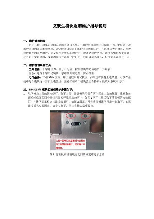
三,ER45033/T模块的清理维护步骤如下:1.取下模块上盖的固定螺钉,取下上盖,注意模块尾部有两个固定上盖的螺钉;注意取前面板时底面的四个螺钉只需松开靠前端的两个,如图1所示。
然后取下前面板的安装螺钉,并拔下显示板连接线缆的插头,如图2所示,再将前面板连同风扇一起取下。
如果线缆插头点胶固定,请小心取下,防止将插头底座拔出。
图1 前面板和机箱底壳之间的固定螺钉示意图图2 显示板与控制板之间的连接线缆图3 风扇安装位置(注意风扇安装方向,切勿装反)2. 用毛刷将散热器以及PCB板上的灰尘清扫干净,特别注意进风口处的器件,需要仔细清理。
然后用风枪将残留在器件和PCB板上的灰尘吹掉,可以从出风口顺序往进风口方向吹扫(从出风口往进风口方向吹更容易将灰尘清理干净),直至将残留灰尘吹出机箱外。
3. 将拆下的面板风扇组件也清理干净。
(以下是ER45033/T清理后重新装配的步骤)5. 现将风扇安装在面板上,将面板靠近机箱,插上显示板连接线缆,如图2所示;然后将面板组件安装到机箱上,装上侧面以及背面的安装螺钉。
6. 将电感板装上,注意电感板的安装螺钉要拧紧。
确认接线缆两端是否都安装到位。
艾默生精密空调维护手册v12

艾默生精密空调维护手册v12 XXX精密空调维护手册H52主办2016年4月21日订定目录第一章概述1.1简介本手册旨在为用户提供Emerson精密空调的维护指南。
1.2主要部件1.2.1室内机室内机是Emerson精密空调系统的核心部件。
它包含压缩机、蒸发器、冷凝器和膨胀阀等重要组件。
1.2.2控制器控制器是Emerson精密空调系统的关键部件。
它可以监测和控制室内温度、湿度和空气质量等参数,确保系统正常运行。
第二章各个功能模块介绍2.1制冷系统制冷系统是Emerson精密空调系统的核心部件。
它可以通过压缩、冷凝、蒸发和膨胀等过程将热量从室内移出,使室内温度保持稳定。
为了确保制冷系统正常运行,用户需要定期清洗和更换过滤器、检查制冷剂压力和泄漏等问题。
删除明显有问题的段落)改写后的第一章概述:XXX精密空调维护手册旨在为用户提供维护指南,确保系统正常运行。
室内机是系统的核心部件,包含压缩机、蒸发器、冷凝器和膨胀阀等重要组件。
控制器是关键部件,可以监测和控制室内温度、湿度和空气质量等参数。
改写后的第二章各个功能模块介绍:制冷系统是Emerson精密空调系统的核心部件,通过压缩、冷凝、蒸发和膨胀等过程将热量从室内移出,使室内温度保持稳定。
为确保制冷系统正常运行,用户需要定期清洗和更换过滤器、检查制冷剂压力和泄漏等问题。
2.1.1 压缩机压缩机是空调系统中最重要的组件之一。
其主要功能是将低压低温的气体压缩成高压高温的气体,使其能够在冷凝器中释放热量。
2.1.2 冷凝器冷凝器是将压缩机压缩出的高温高压气体冷却成高压液体的重要组件。
其主要原理是通过散热器来散热,使气体冷却并凝结成液体。
2.1.3 膨胀阀膨胀阀是空调系统中的一个重要组件,其主要功能是控制制冷剂的流量和压力。
它可以通过自动调节制冷剂的流量来维持系统的稳定性。
2.1.4 蒸发器蒸发器是空调系统中的一个重要组件,其主要功能是将低压低温液体制冷剂蒸发成低温低压气体,吸收空气中的热量,从而实现制冷效果。
艾默生机房空调PEX系列产品说明书
艾默⽣机房空调PEX系列产品说明书科海机房(深圳)办事处艾默⽣恒温恒湿空调产品资料(艾默⽣)⼒博特PEX系列恒温恒湿空调介绍⼀、PEX系列描述科海机房(深圳)办事处艾默⽣恒温恒湿空调产品资料科海机房2⼆、PEX 系列技术参数1、同等制冷量条件下,占地⾯积最⼩。
侧⾯及背⾯不需要维护空间,前⾯只需要600mm维护空间。
2、可拆卸后搬运,保证重新组装与整机⽆差别,适合特殊场地搬运(如利⽤⼩电梯或狭⼩通道)。
3、快速除湿功能设计,能有效的降低除湿能耗。
4、Copeland(艾默⽣⼦公司)涡旋式压缩机,能效⽐⾼,运⾏可靠。
5、⼤表⾯积的 V 型蒸发器盘管,使热交换更快,更有效率,“V”型结构有利于蒸发器表⾯的空⽓分配更加均衡,确保节能。
6、6秒可以产⽣纯净蒸汽的远红外加湿系统,湿度控制精确,可以适应各种⽔质,清洗维护⽅便。
7、⼤屏幕LCD全中⽂显⽰屏,图形化显⽰多种信息,并提供帮助菜单。
8、提供先进的iCOM微处理控制器,强⼤的联机控制功能。
控制精确,PeX系列空调系统能精确地进⾏温湿度控制。
温度可设定在±1℃,湿度可设定在±1%RH。
能效⾼,PeX系列空调采⽤了Copeland⾼效涡旋压缩机。
该压缩机具有独特的V字形翅⽚管式换热器和精细设计的分液头,使得空调内部流场更加均匀,冷媒分配更加合理,从⽽极⼤地提⾼了换热器的换热效率,使整机达到⾼效节能的效果。
⽅便耐⽤:经久耐⽤的机件,结构紧凑,整体尺⼨⼩;独特的碳钢铆钉铆接的⾻架机⾝,既稳定坚固⼜容易拆分,可以实现极限条件下搬运;内外两层,中间采⽤防⽕隔热棉,机⾝内的保温性能良好;one-bay、two-bay、three-bay结构件通⽤性较⾼,⼤⼤降低了易消耗件(如过滤⽹等)的规格。
采⽤真正的模块化设计思路。
⽣产的单制冷回路/双制冷回路 PEX系列精密空调,可以提供单机的制冷量为20KW⾄100KW,并可组合在⼀起。
即能满⾜现阶段的使⽤,⼜能适应未来发展的需求,具有⾮常⼴泛的应⽤范围。
艾默生开关电源维护操作手册(精简版)

艾默生开关电源维护手册目录第一章基本原理 3一、系统的工作原理 3二、产品型号说明 3三、负载下电和电池保护 4 第二章基本面板图形 5一、全省使用的艾默生开关电源型号清单 6二、几种常见的监控模块面板图形及说明 6三、几种常见的整流模块面板图形及说明7 第三章参数设置部份9一、开关电源常用参数设置9二、几种常用开关电源监控模块参数设置101、PS481000-2/100开关电源(PSM-A监控模块)102、PS48300-1A/30开关电源(PSM-A10监控模块)3136 3、Ps24600-75、PS48400-2C/50开关电源(PSM-A11监控模块)的菜单结构4、PS48600-3/2900开关电源(MF500监控模块)375、PSM-7监控模块(PS24480-40开关电源) 43 第四章维护制度格式流程56第一章 基本原理1、系统的工作原理开关电源的系统工作原理如图1-1所示,所示市电380V/220V 经交流配电(或交流配电柜)分路进入整流模块,经各整流模块整流得到的-48V/24V 直流电通过汇接进入直流配电,分多路提供给通信设备使用;正常情况下,系统运行在并联浮充状态,即整流模块、负载、蓄电池并联工作,整流模块除了给通信设备供电外,还为蓄电池提供浮充电流;当市电断电时,整流模块停止工作,由蓄电池给通信设备供电,维持通信设备的正常工作;市电恢复后,整流模块重新给通信设备供电,并对蓄电池进行充电,补充消耗的电量。
图1-1二、 产品型号说明(这里列举PS48600-3/2900-X1,PS481000-5/100、EPC4875/25户外电源柜三种型号) 系统型号说明:3 / 2900400A,600A 两种)PS 48 XXXPS 48 XXX - 3 / 2900-XX 整流模块额定功率(2900W )电源系统版本号输出额定电流(有400A,600输出额定电压(-48V )电源系统扩展版本号(X1,X2,X3,X4,X5)PS 48 1000 -5 / 100整流模块额定电流(100A )版本号输出额定电流(1000A )输出额定电压(-48V )EPC 48 75 / 25 AA:南方型 B:北方型25A整流模块额定电流75A额定电压48V户外电源柜(Emerson Power Cabinet)整流模块型号说明:版本号输出额定电流(100A)输出额定电压(-48V)监控模块型号说明:3*2U)三、负载下电和电池保护负载下电和电池过放电保护的工作过程如图1-3所示。
艾默生机房精密空调的重点日常维护

艾默生机房精密空调的重点日常维护文档编制序号:[KK8UY-LL9IO69-TTO6M3-MTOL89-FTT688]艾默生机房精密空调的重点日常维护时间:2012-06-20 17:02来源:未知作者:zx点击:1563次一、的结构及工作原理??精密主要由压缩机、冷凝器、膨胀阀和蒸发器组成。
??一般来说空调机的制冷过程为:压缩机将经过蒸发器后吸收了热能的制冷剂气体压缩成高压气体,然后送到室外机的冷凝器;冷凝器将高温高压气体的热能通过风扇向周围空气中释放,使高温高压的气体制冷剂重新凝结成液体,然后送到膨胀阀;膨胀阀将冷凝器管道送来的液体制冷剂降温后变成液、气混合态的制冷剂,然后送到蒸发器回路中去;蒸发器将液、气混合态的制冷剂通过吸收机房环境中的热量重新蒸发成气态制冷剂,然后又送回到压缩机,重复前面的过程。
??二、计算机机房中选用精密专用空调的原因??1、温度、湿度控制对计算机机房的重要性??在计算机机房中的设备是由大量的微电子、精密机械设备等组成,而这些设备使用了大量的易受温度、湿度影响的电子元器件、机械构件及材料。
温度对计算机的电子元器件、绝缘材料以及记录介质都有较大的影响;如对半导体元器件而言,室温在规定范围内每增加10℃,其可靠性就会降低约25%;而对电容器,温度每增加10℃,其使用时间将下降50%;绝缘材料对温度同样敏感,温度过高,印刷电路板的结构强度会变弱,温度过低,绝缘材料会变脆,同样会使结构强度变弱;对记录介质而言,温度过高或过低都会导致数据的丢失或存取故障。
??湿度对计算机设备的影响也同样明显,当相对湿度较高时,水蒸汽在电子元器件或电介质材料表面形成水膜,容易引起电子元器件之间出现形成通路;当相对湿度过低时;容易产生较高的静电电压,试验表明:在计算机机房中,如相对湿度为30%,静电电压可达5000V,相对湿度为20%,静电电压可达10000V,相对湿度为5%时,静电电压可达20000V,而高达上万伏的静电电压对计算机设备的影响是显而易见的。
(完整word版)艾默生说明书标准-3版
变频调速器(艾默生)使用说明感谢您购买盾安空调,为使您更好的使用和维护机组,提高机组的运行效率,延长机组的使用寿命,特请您注意以下几点:1、请您保管好随机资料,在开启或检修机器前,仔细阅读说明书及随机资料.2、安装工作及首次开机工作必须由受过训练的专业人员进行。
安装按电控柜铭牌的编号将其与机组编号一一对应的互相匹配.注意:请一一对应匹配.一、查收随机资料及附件1、附件:①尼龙接头;②包塑金属软管;③导线若干等。
二、柜体安装1、安装位置:控制柜安装机组旁边的墙壁上,如无墙壁,则用户自行做支架安装,建议安装位置与机组风机段距离≤3米,高度(以操作界面为准):1。
4~1.5米,接线出厂标配为3米,若接线距离>3米,则接线部分由用户自行解决。
2、安装方式:明装.采用壁挂式安装,安装孔及尺寸见电控柜实体.三、放线、接线、走线1、柜式空调机组电控柜固定完成后,按电机接线盒到电动机接线端子的弯曲距离放线。
2、按电气原理图、电气接线图、随机附件接好电源进线、接地线等导线。
3、若控制柜含BA干接点,则所需电缆用线由用户自备,建议使用线径0.75mm2导线。
调试(0。
7~5.5)kW变频器一、数字操作器TOP—LED02各部说明:PRG:编程键;FUNC/DATA:功能/数据键;>>:移位键;∧:递增键;∨:递减键;RUN:运行键;-1-STOP/RESET:停止/复位。
详细说明见随机变频器《使用手册》二、变频器内部参数设置注意:若Array变频柜含BA干接点,将选择开关打到自动档,通过远程常开无源输入触点对变频器启停进行控制,然后检测运行状态输出、手/自动状态输出的信号输出是否正常;带可选项参数为增加远程调频功能时设置参数,由用户自行确定,接收和反馈信号均为DC0~10V信号,出厂时不含此参数;出厂设置变频器跳码开关CN10跳为V.(7。
5~55)kW变频器一、数字操作器F1A452GZ1各部说明:MENU/ESC:编程/退出键;ENTER/DATA:功能/数据键;PANEL/REMOTE:运行命令通道切换键;>>:移位键;∧:递增键;-2-∨:递减键;JOG:点动键;RUN:运行键;STOP/RESET:停止/复位。
艾默生空调 维保方案

艾默生空调维保方案(总6页)-CAL-FENGHAI.-(YICAI)-Company One1-CAL-本页仅作为文档封面,使用请直接删除维修、维护服务(CRAC)1.维修服务:1)提供保修期内在系统正常使用情况下出现故障所需的维修服务。
2)乙方接到甲方设备故障通知后应迅速作出反应,在指导甲方作简单的应急处理的同时,4小时内到达现场进行故障处理。
3)乙方为甲方提供全天候二十四小时365天(7×24)服务,节假日和业余时间不加收服务费。
乙方应设立全天候二十四小时365天热线服务电话,并指定专人负责处理和联系(24小时值班电话:)2.维护服务:乙方应按下述要求为甲方的设备提供维护服务,并对发现的问题做及时处理。
1)月度巡检乙方每季度为甲方设备提供一次巡检,巡检工作内容包括:过滤器A.检测空气滤网气流是否畅通B.检查过滤器开关主风机A.检查并调整皮带轮和电机的装配,检查是否牢固和正确B.检查并调整皮带松紧程度和状况C.检查风机轴承D.检查风机电机和风机电流压缩机A.检查是否有漏油及油位B.检查压缩机电流C.检查压缩机运转声音和机身温度(运转中)是否正常D.检测压缩机高低压传感器的工作参数加湿器A.检查水盘排水管是否被堵赛B.检查加湿器灯管工作状态工作是否正常C.检查加湿器是否有水垢D.检查进水流量是否适当E.检查近排水阀和电极的工作状态制冷循环部分A.检查制冷管路是否有泄漏B.通过视镜,检查系统是否有水汽C.检查吸气压力D.检查压头E.检查排气压力F.检查热气旁通电气装置A.所有电器外观和动作情况B.检查和紧固所有导线连接C.检查校验运行状态显示2)季度保养:乙方每季度为甲方的设备提供一次例行维护保养,维护保养工作(由厂家工程师组织实施)内容包括:A.检查控制器设置,压缩机吸、排气压力;压缩机工作电流;高低压力报警值;风机噪声及运行电流;加热器过热保护;冷凝器散热情况;制冷循环管路各部件的运行情况;过滤网、加湿器和供排水管路及电气系统等部分的情节情况。
艾默生空调技术手册PEX

图1-1机(双门)1.2 型号说明PEX系列空调型号说明见图2-3所示。
P 1 020 U W P M S 1 R加湿类型:0-无加湿;R-红外加湿;S-电极加湿再热类型:0-无电加热;1-一级电加热;2-二级电加热显示屏形式:S-小显示屏;L-大显示屏电源形式:M-三相/50Hz/400V系统配置:R-制冷剂为R22,涡旋压缩机2个;P-制冷剂为R22,涡旋压缩机1个S-制冷剂为R407C,涡旋压缩机2个;Z-制冷剂为R407C,涡旋压缩机1个冷却方式:A-风冷;W-水冷;G-乙二醇冷却送风方式:U-上出风;F-下出风;D-风管型制冷量级别:××KW机组框架:1-单门;2-双门;3-三门PEX系列1.3 风冷机组技术参数1.3.1 上出风风冷机组技术参数上出风风冷机组技术参数如表3-1所示。
表1-1 上出风风冷机组技术参数上出风风冷机组冷凝器技术参数如下:注意如所需数据未在表中列出,请与艾默生开发部门联系。
1.PEX冷凝器技术参数PEX冷凝器技术参数如表3-2到表3-7所示。
表1-2 PE X冷凝器技术参数(R22,环境温度35℃)表1-3 PE X冷凝器技术参数(R22,环境温度38℃)表1-4 PE X冷凝器技术参数(R22,环境温度41℃)表1-5 PE X冷凝器技术参数(R407C,环境温度35℃)表1-6 PE X冷凝器技术参数(R407C,环境温度38℃)表1-7 PE X冷凝器技术参数(R407C,环境温度41℃)2.低温型室外机技术参数低温型室外机技术参数如表3-8和表3-9所示。
表1-8 低温型室外机技术参数(R22,环境温度35℃)表1-9 低温型室外机冷凝器技术参数(R407C,环境温度35℃)1.3.2 下出风风冷机组技术参数下出风风冷机组技术参数如表3-10所示。
表1-10 下出风风冷机组技术参数下出风风冷机组冷凝器技术参数如下:注意1.下出风机型测试机外静压为20Pa。
艾默生(Emerson) Varible Green 变速电机恒定压差控制器 安装、操作和维护手册说
PN 474766Vari-Green ControlConstant Pressure1 Constant Pressure ControlConstant pressure control is a packaged systemspecifically designed to control a fan with a Vari-Green motor. The controller has two major modes;controlling pressure on the fan inlet, exhaustcontrol; and controlling pressure on the fan outlet,pressurization control. Exhaust control has a cutoutfeature that shuts off the fan when there is nodemand on the system. In both modes closing anoverride input sets the fan to a constant speed.The system includes a fan with Vari-Green motor,pressure tap, and controller. The system is designedwith considerations for lint laden air. Performanceranges from 500-3000 CFM and up to ±1 inch ofpressure. Fan models available are G, CUE, CW,and SQ. Each system shall bear a manufacturer’snameplate.General Safety InformationOnly qualified personnel should install this product.Personnel should have a clear understanding ofthese instructions and should be aware of generalsafety precautions. Improper installation can resultin electric shock, possible injury due to coming incontact with moving parts, as well as other potentialhazards. Other considerations may be requiredif high winds or seismic activity are present. Ifmore information is needed, contact a licensedprofessional engineer before moving forward.Follow all local electrical and safety codes, as wellas the National Electrical Code (NEC) and theNational Fire Protection Agency (NFPA). Whereapplicable, follow the Canadian Electric Code.1. The rotation of the wheel is critical. It must befree to rotate without striking or rubbing anystationary objects.2. Motor must be securely and adequatelygrounded.3. Do not spin fan wheel faster than maximumcataloged fan RPM. Adjustment to fan speedsignificantly affects motor load. If fan RPM ischanged, motor current should be checkedto make sure it is not exceeding the motornameplate amps.4. Do not allow the power cable to kink or comein contact with oil, grease, hot surfaces,or chemicals. Replace cord immediately ifdamaged.5. Verify that the power source is compatible withthe equipment.6. Never open access doors to a duct while the fanis running.2ReceivingUpon receiving the product check to make sure all items are accounted for by referencing the bill of lading to ensure all items were received. Inspect each crate for shipping damage before accepting delivery. Notify the carrier if any damage is noticed. The carrier will make notification on the delivery receipt acknowledging any damage to the product. All damage should be noted on all the copies of the bill of lading which is countersigned by thedelivering carrier. A Carrier Inspection Report should be filled out by the carrier upon arrival and reported to the Traffic Department. If damaged upon arrival, file a claim with carrier. Any physical damage to the unit after acceptance is not the responsibility of Greenheck Fan Corporation.UnpackingVerify that all required parts and the correctquantity of each item have been received. If any items are missing, report shortages to your local representative to arrange for obtaining missing parts. Sometimes it is not possible that all items for the unit be shipped together due to availability of transportation and truck space. Confirmation of shipment(s) must be limited to only items on the bill of lading.HandlingThe motor amperage and voltage ratings must be checked for compatibility to supply voltage prior to final electrical connection. Wiring must conform to local and national codes. Consult local code authorities for specific requirements.StorageProduct is protected against damage during shipment. If the product cannot be installed and operated immediately, precautions need to betaken to prevent deterioration of the product during storage. The user assumes responsibility of the product and accessories while in storage. The manufacturer will not be responsible for damage during storage. These suggestions are provided solely as a convenience to the user.Indoor OnlyDo not store this product outdoors. The ideal environment for the storage of this product isindoors, above grade, in a low humidity atmosphere which is sealed to prevent the entry of blowing dust, rain or snow. Temperatures should be evenly maintained between 30° to 110°F (-1° to 43°C) (wide temperature swings may cause condensation and “sweating” of metal parts). All accessories must be stored indoors in a clean, dry atmosphere.Remove any accumulations of dirt, water, ice, or snow and wipe dry before moving to indoor storage. Allow cold parts to reach room temperature to avoid “sweating” of metal parts. To dry parts andParts Needed (Not provided by Greenheck)• 18 - 20 gauge 3-wire plenum rated control wire • 1/4 inch inside diameter plastic tubing• Normally Open switch or relay for optional remote overridePressure TapsEither room or duct pressure taps may be used. Be sure to mount them in the room or duct system you intend to control.Be careful not to pinch or kink the pressure tubing anywhere along its length.Condensation running down the interior of thepressure tubing may damage the controller’s sensor. Forming a drip loop in the tubing just before it enters the Greenheck Constant Pressure Controller is good practice. (The distance from the bottom of the loop to the controller’s pressure port should be one to two inches [2.5 to 5 cm] greater than the highest staticpressure, including error conditions, in the system.)Drip Looppackages, use a portable electric heater to get rid of any moisture buildup. Leave coverings loose to permit air circulation and to allow for periodic inspection. The unit should not be stored on the floor.Inspection and Maintenance During StorageWhile in storage, inspect product once per month. Keep a record of inspection and maintenance performed. If moisture or dirt accumulations are found on parts, the source should be located and eliminated.Installation and Setup GuideThis guide provides instructions for how toinstall, wire and program the control system for use when constant pressure in a duct or room system is required. This does not cover ductwork recommendations or other considerations. When installed, this control system will automatically vary the speed of the fan to maintain a constant pressure within the system.3It is best to mount the wall static pressure pickup port using an electrical box. A simple hole in the wallboard may be used, but in any case be sure that the foam gasket on the back of the pickup seals tightly against the wallDuct Pressure TapPositioning the duct pressure tap to get the best results depends on the layout of the system. For stacked systems, locate the pressure tap 1/3 of the way from the bottom of the duct.Select a location on the duct that is a minimum of 1.5 duct diameters upstream or downstream from any dimensional change, elbow, damper or other obstruction. The mounting location should be towards the top of horizontal run duct toprevent condensation from entering the tube. On rectangular duct mount the pressure tap away from the corners. Remove any exterior insulation; insulation may be replaced after installation. 1. Drill a 3/8” hole in the duct where pressure tap isto be installed.2. Place the 6” tube into the hole and move themounting base up to the duct. Orientation does not matter.3. For round duct rotate the tap so the mountingholes contact the duct4. Using the supplied self drilling zip screws, attachthe duct pressure tap to the duct compressing the gasket evenly.5. Connect tubing from the barbed port to thepressure controller.6. When a total and static probe are used tomeasure velocity pressure, mount the pressure taps as shown in the diagram below. Be sure to orient the total pressure tap in the direction of airflow. Select a location in the ductwork that is at least 5 duct diameters from any elbows, dampers, transitions or diffusers.Electrical Box1. Using a 1/16” Allen wrench, separate the mountingbase and the cover by driving in the 1/16” Allen screws until the cover comes free. Driving the screws in prevents you from losing them.2. Pull the pressure tubing through the wall and outof the junction box, leaving about two inches free. 3. Secure the pressure tubing to the pressure fitting.4. Secure the base to the box using the #6-32 x 3/4inch mounting screw provided. 5. Attach cover by latching it to the top of the base,rotating the cover down and snapping it into place. 6. Secure the cover by backing out the lock-downscrews using a 1/16” Allen wrench until they areflush with the bottom of the cover.Room Pressure TapMount the static pressure pickup port in an area that is representative of the zone near the center of the zone. Do not mount in a closet or other enclosed space that is in the zone being monitored. Avoidmounting locations in areas that are prone to drafts.Electrical Box MountElectrical Box Mounting PlateCover4Wall Mount1. Using a 1/16” Allen wrench, separate the mount -ing base and the cover by driving in the 1/16” Allen screws until the cover comes free. Driving the screws in prevents you from losing them.2. Drill a ¾” hole in the drywall to relieve the pressurefitting where the pressure tap is to be installed.3. Place the mounting base pressure fitting in the ¾”hole and align the mounting base to the wall.4. Using a pencil, mark out the two mounting holes onthe wall.5. Drill two 3/16” holes in the center of each markedmounting hole. Insert a drywall anchor into each hole. 6. Pull the pressure tubing through the wall and out ofthe 3/4” hole, leaving about two inches free.7. Secure the pressure tubing to the pressure fitting.8. Secure the base to the drywall anchors using the#6 x 1 inch mounting screws provided.9. Attach Cover by latching it to the top of the base,rotating the cover down and snapping it into place. 10. Secure the cover by backing out the lock-downscrews using a 1/16” Allen wrench until they are flush with the bottom of the cover.Constant Pressure Control• The Constant Pressure Control contains an integral pressure transducer.• Mount the Constant Pressure Control box in an accessible location as close as possible to the pressure tap and fan. Keep wiring lengths between the Constant Pressure Control and the fan to 200 feet or less. Keep pressure tubing lengths between the Constant Pressure Control and the pressure taps to 100 feet or less.• Mount the Constant Pressure Control in thevertical position with the tubing connectors in the down position.• One Duct Tap – Maintains constant pressure in duct based upon space pressure where the Constant Pressure Control is mounted – Connect the “H” tubing connector on the ConstantPressure Control to the pressure tap using 1/4-inch tubing. The “L” tubing connector remains open to atmosphere.• One Duct Static Tap and One Duct Total Tap – Maintains a constant velocity pressure in a duct. This allows the system to automatically adjust the airflow in a system to compensate for filter or coil loading. Connect the “H” tubing connector on the Constant Pressure Control to the total pressure tap and connect the “L” tubing connector to the static pressure tap using 1/4” tubing. The resultant measurement will be velocity pressure. • System Balancing – The Constant Pressure Controller can maintain a velocity pressure from 0 to 1”. To balance the system, calculate the velocity pressure required for the system based on the intended CFM and duct area:Where A is the duct area in ft 2.Set parameter P11=0 and parameter P01 (the pressure setpoint) to the desired velocitypressure. If airflow verification is needed, external CFM measurements can be taken and the velocity pressure can be adjusted until the desired airflow is achieved.• One Room Tap – Maintains constant pressure in a room based upon space pressure where the Con -stant Pressure Control is mounted – Connect the “H” tubing connector on the Constant Pressure Control to the pressure tap using 1/4-inch tubing. The “L” tubing connector remains open to atmosphere.• Two Room Taps – Maintains a constantdifferential pressure between two rooms, allowing the Constant Pressure Control to be mounted in a remote location - Connect the “H” tubing connector on the Constant Pressure Control to the pressure tap in the high pressure room using 1/4-inch tubing. Connect the “L” tubing connector on the Constant Pressure Control to the pressure tap in the low pressure room using 1/4-inch tubing.• Make sure the tubing is not kinked or punctured .WiringSee diagram on page 7 for wiring overview.• Control Box to Factory Mounted TransformerControl Input• Optional Remote Override:Connect a normally-open switch between terminals J3+ and J3- on the controller. Closing this switch will activate the remote override feature. Opening the switch will de-activate the override.Wall MountMounting Plate Cover5Normal Operation (J5 = RUN)The Constant Pressure Control ships from the factory to control pressure on the inlet of the fan with a setpoint of -0.10 inches of water pressure, the display showing real time duct pressure in inches of water and the cutout disabled. Pressing the buttons on the controller lid will show the following for 10 seconds;• Enter, LED color Cyan, Cutout percent stored in parameter P06• Up/Increase, LED color Yellow, Setpoint pressure stored in parameter P01.• Down/Decrease, LED color Green, Real time output voltage in percent.Note: If Display Units parameter P04 is set to 0, then the normal display will show real time output voltage in percent and pressing the Down/Decrease button will display real time duct pressure.Pressure DisplayThe pressure display reads in engineering units. The display will only indicate pressures from 1.00 to -1.00 inches of water. If the pressure is above 1.00 or below -1.00 inches of water then, the display will flash the 1’s digit.Programming (J5 = PROG)Programming allows the user to customize the operation on the Constant Pressure Control. The color of the LED is red during programming mode. If power to the controller is lost, all settings will be retained.General Programming• Place the J5 jumper on the PROG position,LED = Red • During programming, output to fan is disabled • The display will read P01• Press the Up/Increase or Down/Decrease button to change the parameter number• Press the enter button to edit the parametero Press the Up/Increase or Down/Decreasebutton to change the parameter. Pressing and holding the button will scroll the numbers o Press the Enter button to save the change • The display will read the parameter number just edited• Continue until all the parameters needing editing are completed• Always stop with a parameter number showing •Place the J5 jumper on the RUN position,LED = GreenPositionPositionController OperationThe Constant Pressure Control has three buttons accessible through the lid: Enter, Up or Increase(▲), and Down or Decrease (▼). Additionally on the circuit board inside the lid is jumper J5. J5 is used to set the controller into normal operation, RUN, or programming mode, PROG.6Cutout Percent, Parameter P06(Fan inlet control only)Factory Default = 20%20% = Cutout disabled, fan on continuously.20% to 100% in 0.1% incrementsThe cutout feature can only be used if the system utilizes powered fans such as bathroom fans or dryers. It will not function properly if passive devices are installed in the system such as motorized dampers.The cutout percent needs to be set if you would like the exhaust fan to turn off when there is no demand on the system. The default value is set at 20%. If the exhaust fan is required to operate at all times, leave the cutout percent value at 20%.When the output percent is less than the cutout percent, the cutout timer is activated (The timer value is in parameter P07). After the time has elapsed, the fan will shut off.Note: A cutout percent value is only valid for a discreet pressure set point. When the pressureset point is changed, the cutout percent value must be adjusted as well. It is recommended that you make sure your pressure set point is correct before continuing.To set the cutout percent value, the following steps need to be followed:• Set normal operation and verify the system is maintaining the desired pressure set point withno other equipment (dryers, bathroom fans, etc.) operating.• After the pressure has stabilized at the set point, press the Down/Decrease button to show thepercent output voltage. Take note of this value.(The value will fluctuate slightly within +/- 2%. A mental average will be adequate.)• The recommended Cutout Value is 1-2percentage points above the value you notedin the previous step. See above for a graphicalrepresentation.When the system is running and the output percent is less than the cutout value, the LED will flash. After the cutout time has elapsed, the fan will turn off. When the fan turns off, the display will show “OFF” and the LED will flash.Pressure Set Point, Parameter P01 Factory Default = -0.10 inches of water.-1.00 to 1.00 inches of water in increments of 0.01 inches.Auto Zero, Parameter P02Factory Default = 00 = entry condition1 = Perform Auto ZeroAuto zero sets the zero pressure reading of the controller. Greenheck recommends performing auto zero after installation and before first operation. Place a piece of tubing from tubing connector “H” to tubing connector “L”. Set value to 1 and press the Enter button. The LED will turn white. Auto zerois complete when the LED turns red. Remove the tubing from the tubing connectors and reconnect the pressure tap.Factory Defaults, Parameter P03Factory Default = 00 = entry condition1 = Set all parameters to the factory default setting Display Units, Parameter P04Factory Default = 10 = Normal display is output percent1 = Normal display is inches of waterAlgorithm Gain, Parameter P05Factory Default = 00 = Factory gains1 = Gain set A2 = Gain set BIf gain set 0 does not achieve stable operation use one of the other sets to achieve stable operation.7One of two things must happen for the system to return to normal operating mode:• The controller will sense when a dryer, bathroom fan, etc. is turned on and will vary the exhaust fan speed appropriately.• If for some reason the system needs to bemanually awakened from cutout mode, hold the Enter button for 5 seconds and the system will return to normal operating mode.If the controller will not shut the fan off, verify that the cutout value is correct and that the timer has started by looking for the flashing LED. If the flashing LED is not displayed, then the cutout value needs to be adjusted. Remember the cutout value should be set when there is no demand on the system.If the controller shuts the fan off when there isdemand on the system, the cutout value is too high. Lower the value and observe the operation of the system.Cutout Delay Timer, Parameter P07Factory Default = 30 seconds0 to 100 seconds in 1 second increments See parameter P06 for operational details.Override Output Percent, Parameter P08Factory Default = 100%20% to 100% in 1% incrementsDuring normal operation, when the remote override switch is closed, the fan will immediately rampto P08% speed and stays there until the remote override switch is opened. The override can beactivated by any normally-open voltage-free contact. Closing the contact will activate the override.The LED will turn red and the display will show Ovr when the override switch is closed.Pressure Input Filter, Parameter P09Factory Default = 0 seconds 0 = No Filter0 to 10 seconds in 1 second incrementsPressure filter time constant. Set higher than zero if wind gusts interfere with stable operation.Start Up Timer, Parameter P10Factory Default = 10 seconds10 to 30 seconds in 1 second incrementsAt power up, set the output to 2 VDC for the time in parameter 10, then resume algorithm control. Fan-Inlet/Fan-Outlet Control, Parameter P11Factory Default = 1, fan inlet control 0 = Fan Outlet Control 1 = Fan Inlet ControlThe controller has two major modes; controllingpressure on the fan inlet, and controlling pressure on the fan outlet.Exhaust fans use inlet control. Supply fans use outlet control. Inline fans may use either inlet or outlet control depending on the location of the tap.If controlling velocity pressure, set P11=0.Wiring Diagram8AMCA Publication 410-96, Safety Practices for Users and Installers of Industrial and Commercial Fans, provides ad -ditional safety information. This publication can be obtained from AMCA International, Inc. at: .Greenheck Vari-Green Motor catalog provides additional information describing the equipment, fan performance, available accessories, and specification data.Phone:(715)359-6171•Fax:(715)355-2399•E-mail:*********************•Website:WarrantyCheck that pressure taps are a minimum of 1.5 duct diameters upstream or downstream from any dimensional change, elbow, damper or other obstruction.Make sure there are no kinks or punctures in the tubing between the Constant Pressure Control and the pressure taps.Make sure there are no kinks or punctures in the tubing between the Constant Pressure Control and the pressure taps. Try algorithm gain set A or B.A cutout percent value is only valid for a discreet pressure set point. When thepressure set point is changed, the cutout percent value must be adjusted as well. It is If the controller will not shut the fan off, verify that the cutout value is correct and that the timer has started by looking for the flashing LED. If the flashing LED is notIf the controller shuts the fan off when there is demand on the system, the cutout value is too high. Lower the value and observe the operation of the system.Troubleshooting474766 • Constant Pressure Control, Rev. 2, Oct. 2011Copyright 2011 © Greenheck Fan Corp.。
- 1、下载文档前请自行甄别文档内容的完整性,平台不提供额外的编辑、内容补充、找答案等附加服务。
- 2、"仅部分预览"的文档,不可在线预览部分如存在完整性等问题,可反馈申请退款(可完整预览的文档不适用该条件!)。
- 3、如文档侵犯您的权益,请联系客服反馈,我们会尽快为您处理(人工客服工作时间:9:00-18:30)。
二、安装特性 ——冷凝器安装
CM+系列室外冷凝 器可垂直安装及 叠加安装,可节 省室外安装空间
二、安装特性 ——润滑油注入
谷轮柔性涡旋压缩机使用常规 的白油(Sontex200LT )。白 油可以和3GS油互融,在某些 情况下(例如管路较长)现场 需要加油,可以使用3GS油检 查压缩机铭牌上原始注油量, 保证机组的正常运行。
四、维护特性 ——维修阀设计
采用制冷系统维 修阀,可方便对 机组的制冷状态 进行监控。同时 ,方便系统加注 制冷剂,有利制 冷系统维护
维修阀
四、维护特性 ——加湿器设计
采用可现场清洗 的加湿系统,可
延长加湿器的使 用时间,节约运 行、维护成本
可现场拆卸 型电子型加 湿器
加湿器的电极 可根据需பைடு நூலகம்调 整及更换
四、维护特性——控制器设计
LECS15
先进的带图形显示的微处理控制器
带背景灯的240 x 180 矩阵 LCD 显示器
PID 控制
全中文显示器
提供RS232通讯接口及协议
最近 8 小时的温度和相对湿度图形曲线显示
最近的100个报警信息历史储存
故障保护功能
– 由安装在控制板上的电池对机组的设定值和报警历史进行保护
地下水 备用输出1、2
降温、过滤、加湿服务
电池电量不足
降温 加热 加湿 除湿 备用/一 般告警 调制O/P1,2,3
断电 系统保护告警 IO通信
PCB传感器故障
通信 [1]
数据/时间未设 参数损坏
远程/校验和故障
主频率损失
波特率/类型
检查电池
维护间隔时间 [2]
降温 过滤 加湿
高级设置[2]
传感器校正[2]
三、安装调试步骤 ——调试步骤
1、检查机组的外观和内部是否有损坏。 2、去除运输的木快和紧固的连杆。 3、把螺丝和各种插头上紧或接牢。 4、检查机组安装是否符合规范(包括电气部分)。 5、检查机组保压压力是否正常。 6、从机组压缩机的高压侧静态充制冷剂,到机组的压力与制冷剂瓶的
压力平衡(100PSI)为止,关闭双头表的高压阀门。 7、检查输入电压。 8、给机组供电,调整机组的温度设定点,使机组处于制冷状态。
高、低压电器 正面维护
送风风筒正面 维护
涡旋压缩机正 面维护
加湿器正面维 护
四、维护特性——过滤器维护简便
过滤器采用金属外壳,方 便过滤滤芯的更换过滤器 ,可以从机组正面和前面 更换,使机组维护更加简 单,减少维护空间。
四、维护特性 ——除湿设计
V型蒸发器 盘管,盘管 面积大,送 风均匀
除湿电磁阀
挑战者M+系统(Challenger M+)
Liebert精密空调系列CM+产品解决方案
(30KW ~ 100KW单机)
送风和冷却方式依机房现实场景而定
DATAMATE系统
Liebert精密空调DataMate产品解决方案
(5.8KW ~ 8.6KW单机)
用户机房对环境的基本要求
• 保持温度恒定(控制在22oC-24oC,温差1-2oC之内) • 保持湿度恒定(控制在50%RH,精度3%~5%RH之
室内机组摆放
——机组的前面只须留有600MM的维修 空间,机组两边及后面无须留有 维护空间
因此—— • 机组可以靠装 • 机组可以并排摆放
CM+系列机房空调是同容量机组中 占地间和维护空间需求最小的机 组,可大大提高机房的使用率
阴影处为所须的维护空大间 型(L)
二、安装特性 ——风帽安装
风帽安装
室内直接送风型上送风机组可 采用送风风帽,现场安装简便
500-800
电信设备对运行环境的要求
0.9 - 1.0 10-14 30 - 60 22o - 24oC ASHRAE 20%+ 50% + 5%
机房空调
提供 提供 提供 8760 8年 断电可自动恢复 N+1 / N+2
典型的空调系统
热空气
典型制冷系统 1.蒸发器 2.冷凝器 3.压缩机 4.膨胀阀
艾默生机房空调系统 产品与安装维护
艾默生网络能源有限公司 机房空调产品部 王前方
空调简介
➢ 空调 即空气调节的简称。
➢ 指的是要在室内创造一种环境,使其中的空气参数例 如温度、湿度、洁净度、气流速度、压力、气味含量 等,保持在设定的范围内,以满足室内设定的各参数 要求。
➢ 机房空调调节的主要参数:
低维护需求
——减少维护量
机组前面只需600mm的维护空间 ——维护简便
极高的可靠性
完善的匹配设计 在实验室经过严格测试 在设计及生产中注重质量
——设计合理 ——运行可靠 ——保证质量
CM+系统充分考虑到电信机房的特点设计更加合理,节 省空间,方便安装从而提高机组整体的市场竞争能力
二、安装特性 ——安装简便性(占地)
二、安装特性 ——系统简介
高效性
高效能涡漩式压缩机 ——耗电低
改良的盘管设计
——节能耗
低马力风机
——效率高
新型的微电脑控制器 ——控制精
灵活性
最小的占地空间
——节省空间
全部的正面维护、维修——维护简便
机组可现场拆卸
——搬运灵活
二、安装特性 ——系统简介
出众的可维护性
所有部件均可进行维修
——节约成本
室外35℃
热量转移
冷空气
冷媒蒸发 室内24℃
回风
回风暖空气
送风解决方案
•上送风机型(风道送风)
送风解决方案
•上送风机型(风帽送风)
送风解决方案
•下送风机型
冷却系统解决方案-风冷
制冷剂
冷却系统解决方案-水冷
冷却系统解决方案-乙二醇冷却
冷却系统解决方案-乙二醇自然冷却
冷却系统解决方案-冷冻水
二、安装特性 ——支架安装
支架安装
下送风型机组须安装地板支架与导流板, 使机房承载更加均匀,送风更加流畅
二、安装特性 ——管路安装
U
管路安装
当室外机组安装高 于室内机组时,需 注意回油弯及反向 液弯的安装,可防 止压缩机产生液击 及油击
室外机组
型回油弯
存油弯
室内机组
U 型回油弯
室外机高于室内机的安装示意图
温度
湿度
洁净度
机房正压
空调简介
空气调节系统的分类
按用途,空调系统可分成二类: ➢ 工艺性空调—空调参数值的选择须满足工艺过程对空气参数的要求。
例如:机房精密空调、手术室空调、电子厂房空调等 ➢ 舒适性空调--空调参数值的选择须满足人的工作条件和休息条件。
例如:家用空调、商用空调等 按处理装置可分:
低电压保护
运行/备用机自动转换功能
先进的控制系统,大屏幕全中文带图形显示功能,提高了系统的可维护性。
报警存储信息大,开放接口,方便系统的日常维护
主菜单
告警菜单
设定值控制
告警状态 查看有效告警
告警记录
回风温度/湿度 C/ % RH
查看最近100个告 警
告警重设[1]
HP1和2 LP 1和2 加湿器水量低 一般告警 记录
电流。 13、调整设定点,使机组处于加热状态,观察加热是否正常,并记录
电流。 14、调整设定点,使机组处于除湿状态。观察除湿是否正常。 15、测量风机电流并记录。 16、检查风机皮带的松紧度,并调整。 17、恢复日常工作正常设定值。
四、维护特性 ——全正面维护
全正面维护,减少维护空间需求
图形菜单
系统设置[1]
HH:MM:SS DD/MM/YYYY
查看前48小时 -回风温度/湿度 -供气温度/湿度
设备号
启动延时
冷启动延时 风扇运转 转换远程停机 转换一般告警 压缩机倒换 压缩机交换间隔 温控方法
标准告警 高温 低温 高湿 低湿 空气损失 高压1和2
低压1和2
加湿器水量低
AOM控制[2]
先进的盘管构造与除湿方法设计,降低了系 统的电能消耗,大大降低了运行维护费用
四、维护特性 ——风冷冷凝器
- 机组框架由不锈钢连接件与船用 等级耐腐蚀铝材组成
- 高效调速风扇 - 一体式风机组合采用独特减震设计 - 维护要求极低的风扇电机适用于各
种气候条件 - 单/双制冷回路设计 - 适用于各种恶劣气候条件 - 可选择水平/垂直两种方式进行安装
对特别功能的要求
再热器 加湿器 集中监控能力 运行时间 (小时/年) 使用寿命 断电自动恢复 备份
人对环境的热影响
100-150
人对环境舒适性的要求
0.6 - 0.7 6-8 5 - 15
21o - 27oC 简单
50% + 15%
普通空调
没有 没有 没有 1000-2500 2~3年 无
无
电信设备对环境的热影响
P-1-D控制[3] 取样时间 P-I-D条件
调制O/P控制[3] 配置模拟O/P
活动地板 加湿器进水 冷凝水排水
地板
二、安装特性 ——管路安装
管路安装
当室外机组安装低于
室内机组时,需注意
管道安装高度差及坡
度的方向,使润滑油
可以顺利返回压缩机
室外机组
室内机组
活动地板 加湿器进水 冷凝水排水 地板
室外机低于室内机的安装示意图
二、安装特性 ——冷凝器安装
室外风冷冷凝器的安装,要注意四周的空间,以保证气流通畅,散热良好。
中央冷水机组
冷却系统解决方案-双冷源
安装和维护
一、前 言
机房空调的研究发展趋势——
– 更加可靠 – 提高系统高可用性 – 使机组更加高效节能 – 易操作,通讯、监控功能更强 – 节省占地空间 – 安装更加简便 – 提高系统的可维护性