processing串口通讯
processing串口通讯
练习:
基础:做一个文字型的电子钟; 进阶:做一个文字加现状的电子钟。
定义变量
连接指定串口
关键语句分析
判断串口是否有数据
myPort.available() > 0 val = myPort.read(); myPort.write('H');
获取串口数据
ቤተ መጻሕፍቲ ባይዱ
输出串口数据
范例1:
import processing.serial.*; Serial myPort; // Create object from Serial class int val; // Data received from the serial port void setup() { size(200, 200); String portName = Serial.list()[0]; myPort = new Serial(this, portName, 9600); } void draw() { if ( myPort.available() > 0) { // If data is available, val = myPort.read(); // read it and store it in val } background(255); // Set background to white if (val == 0) { // If the serial value is 0, fill(0); // set fill to black } else { // If the serial value is not 0, fill(204); // set fill to light gray } rect(50, 50, 100, 100); }
串口通信python实现
串口通信python实现一、什么是串口通信?串口通信是指通过串口接口实现的数据传输过程。
串口是计算机与外部设备之间的一种通信接口,它可以通过一根线(或多根线)进行数据传输。
在计算机系统中,串口是指一个标准的RS-232C接口,它可以连接各种外部设备,如打印机、调制解调器、传感器等。
二、为什么要使用Python实现串口通信?Python是一种高级编程语言,具有简单易学、易于阅读和编写、可移植性强等优点。
同时,Python还具有丰富的库和模块,可以方便地实现各种功能。
因此,在进行串口通信时,使用Python可以简化开发过程,并且提高开发效率。
三、如何在Python中实现串口通信?1. 安装pySerial模块pySerial是一个用于访问计算机上的串行端口的Python模块。
在使用pySerial之前需要先安装该模块。
可以通过pip命令进行安装:```pip install pyserial```2. 打开串口打开一个可用的串行端口需要指定端口号和波特率等参数。
例如:```pythonimport serialser = serial.Serial('COM1', 9600, timeout=0.5)```其中,'COM1'是串口号,9600是波特率,timeout是读取数据的超时时间。
3. 发送数据发送数据可以使用serial模块的write方法。
例如:```pythonser.write(b'Hello, world!')```其中,b'Hello, world!'是要发送的数据。
4. 接收数据接收数据可以使用serial模块的read方法。
例如:```pythondata = ser.read(10)```其中,10表示要读取的字节数。
5. 关闭串口使用完串口后需要关闭它,以释放资源。
可以使用serial模块的close 方法。
例如:```pythonser.close()```四、Python实现串口通信的示例代码下面是一个简单的Python示例代码,用于向串口发送数据,并从串口接收数据:```pythonimport serialser = serial.Serial('COM1', 9600, timeout=0.5)ser.write(b'Hello, world!')data = ser.read(10)print(data)ser.close()```在该示例代码中,首先打开了一个名为COM1的串口,并设置波特率为9600和读取超时时间为0.5秒。
Processing和Arduino互相通讯的方法
北边颇有心气儿的哥们我这是比Байду номын сангаас偷懒的做法其实也可以手动编译需要的视频库放进去但你需要懂一点java
Processing和 Arduino互相通讯的方法
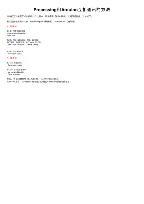
在进行互动装置艺术作品的创作过程中,经常需要【软件+硬件】之间传递数据,方法如下。
我们需要创建两个文件:Receiver.pde(软件端)+ Sender.ino(硬件端)
2、硬件端
第一步:初始化串口 Serial.begin(9600);
第二步:读取传感器信号 val = analogRead(0); Serial.write(val);
然后,将 Sender.ino 烧入Arduino,在打开Processing。 如果一切正常,在Processing端就可以看见Arduino传感器的信号了。
1、软件端
第1步:引用串口通讯库 import processing.serial.*; Serial port;
第2步:初始化通讯端口,例如:COM18 端口查询:设备管理器 - 端口 (COM 和 LPT)
port = new Serial(this, "COM18", 9600);
第3步:读取端口数据 println(port.read());
串行口通信技术相关书籍

串行口通信技术相关书籍Serial communication technology, also known as serial port communication, is a method of transferring data one bit at a time. It is widely used in various applications such as computer networking, industrial automation, and telecommunications. For those who are interested in learning more about serial communication technology, there are many books available on the subject.串行通信技术,也被称为串行口通信,是一种逐位传输数据的方法。
它在各种应用中被广泛使用,如计算机网络、工业自动化和电信。
对于那些有兴趣了解更多关于串行通信技术的人来说,有许多相关书籍可供选择。
One highly recommended book is "Serial Port Complete" by Jan Axelson. This comprehensive guide covers everything from the basics of serial communication to more advanced topics such as USB connectivity and serial device drivers. It is a valuable resource for both beginners and experienced professionals in the field.一本备受推荐的书籍是詹·阿克塞尔森(Jan Axelson)撰写的《串行端口完全手册》。
串口中断接收的流程
串口中断接收的流程英文回答:Serial port interrupt reception is a process that allows the microcontroller to receive data from the serial port without continuously polling for new data. This is especially useful when the microcontroller needs to perform other tasks while waiting for incoming data.The flow of serial port interrupt reception typically involves the following steps:1. Enable the serial port interrupt: This step involves configuring the microcontroller to enable the interrupt for the specific serial port being used. This is usually done by setting appropriate bits in the interrupt enable register.2. Configure the serial port: Before enabling the interrupt, the serial port needs to be properly configuredfor the desired transmission parameters such as baud rate, data bits, parity, and stop bits. This is typically done by setting the appropriate control registers of the serial port.3. Set up the interrupt service routine (ISR): An ISRis a function that is executed when the interrupt occurs. In this case, the ISR for the serial port interrupt should be set up to handle the received data. The ISR should read the received data from the serial port's receive buffer and process it accordingly.4. Enable global interrupts: Before the microcontroller can respond to any interrupts, the global interrupt flag must be enabled. This is usually done by setting the appropriate bit in the microcontroller's control register.5. Wait for the interrupt: Once the serial port interrupt is enabled and the global interrupts are enabled, the microcontroller can wait for the interrupt to occur. This allows the microcontroller to perform other tasks while waiting for incoming data.6. Process the received data: When the interrupt occurs, the microcontroller jumps to the ISR and starts executing the code within the ISR. The ISR should read the received data from the serial port's receive buffer and process it accordingly. This may involve storing the data in a buffer, performing calculations, or triggering other actions based on the received data.7. Clear the interrupt flag: After processing the received data, it is important to clear the interrupt flagto acknowledge that the interrupt has been handled. This is usually done by clearing the appropriate bit in theinterrupt flag register.8. Return from the ISR: Once the interrupt flag is cleared, the microcontroller can return from the ISR and continue executing the main program.Overall, the flow of serial port interrupt reception involves enabling the interrupt, configuring the serial port, setting up the ISR, enabling global interrupts,waiting for the interrupt, processing the received data, clearing the interrupt flag, and returning from the ISR.中文回答:串口中断接收是一种允许微控制器从串口接收数据而无需持续轮询新数据的过程。
基于摄像头的手势控制小车

基于摄像头的⼿势控制⼩车⽤⼿势控制⼩车,⼤家往往喜欢⽤加速度传感器来实现。
最简单的做法莫过于在⼿机上装⼀个App,这个App能检测⼿机的运动⽅向,然后转化为控制信息发给⼩车。
⽽我总是希望⽤⼀种更加有趣,更加⾃然的⽅式去控制⼩车。
微软的Kinect出来后,就有专家写了⼀本书《⽤最⾃然的⽅式与机器对话》。
的确,在Kinect的⽀持下,⼿势控制变得⾮常简单,其互动游戏很受⼈欢迎。
但对于⼿势识别来说,Kinect 并不是唯⼀的选择,⽤普通摄像头我们也能够实现。
Kinect互动游戏⼀、原理分析在上⼀期的⽂章中,我们已经⼤致体验了Processing 的功能。
作为⼀款以互动为特⾊的开源编程语⾔,Processing拥有⼤量的扩展库,并且提供了各种具体的应⽤范例。
其中视频库⽀持外部摄像头,可以实时获取视频画⾯中的每⼀个像素点,并进⾏分析。
在有效的算法⽀持下,我们也可以做到图像分割、物体识别、⼈脸识别、动作识别、运动跟踪等。
同时,Processing⽀持串⼝编程,可以通过串⼝和外部设备(如Arduino)通讯。
这些类似的应⽤,在Processing范例库中都能够找到,技术门槛并不⾼。
⽤⼿势控制⼩车这个作品的运⾏原理如下图。
⼯作原理图⽰当然,由于我们使⽤的是普通摄像头,当然做不到如Kinect的动作识别效果。
虽然从理论上说,Processing也实时识别出⼈的⼿势,但是算法⾮常复杂,不是我们中⼩学的学⽣能够理解。
所以,我试着⽤另⼀种简单的⽅式去做,即让⼩车的操控者带上⼀个特殊颜⾊的⼿套,或者⼿上拿⼀个特定颜⾊的LED灯,Processing对视频⾯⾯的像素点进⾏遍历,找到这⼀颜⾊后,根据座标对⼩车发出控制信息。
简单的说,就是实现⼀个能够捕捉视频中特定颜⾊的程序。
视频中特定颜⾊和控制信息的关系如图所⽰,其中画出⼩矩形的表⽰识别出来的颜⾊。
按照这样的⽅式定义“上、下、左、右”的控制信息,⽐较容易,也⽐较好理解。
但是,如果坐标在左上⾓该怎么处理?如图所⽰。
C语言实现串口通信
C语言实现串口通信在使用系统调用函数进行串口通信之前,需要打开串口设备并设置相关参数。
打开串口设备可以使用open(函数,设置串口参数可以使用termios结构体和tcsetattr(函数。
以下是一个简单的串口通信接收数据的示例代码:```c#include <stdio.h>#include <stdlib.h>#include <fcntl.h>#include <unistd.h>#include <termios.h>int mainint fd; // 串口设备文件描述符char buff[255]; // 存储接收到的数据int len; // 接收到的数据长度//打开串口设备fd = open("/dev/ttyS0", O_RDONLY);if (fd < 0)perror("Failed to open serial port");return -1;}//设置串口参数struct termios options;tcgetattr(fd, &options);cfsetspeed(&options, B1200); // 设置波特率为1200 tcsetattr(fd, TCSANOW, &options);//接收数据while (1)len = read(fd, buff, sizeof(buff)); // 从串口读取数据if (len > 0)buff[len] = '\0'; // 将接收到的数据转为字符串printf("Received data: %s\n", buff);}}//关闭串口设备close(fd);return 0;```这段代码首先通过open(函数打开串口设备文件"/dev/ttyS0",然后使用tcgetattr(函数获取当前设置的串口参数,接着使用cfsetspeed(函数设置波特率为1200,最后使用tcsetattr(函数将设置好的串口参数写回。
stm32多任务多数据串口接收及处理方法
stm32多任务多数据串口接收及处理方法STM32多任务多数据串口接收及处理方法通常涉及到使用中断服务程序(ISR)或轮询方法来接收串口数据,并在多个任务之间分配和同步处理这些数据。
以下是一个基本的步骤和策略,用于实现这一功能:1. 初始化串口:首先,你需要初始化串口以进行通信。
这包括设置波特率、数据位、停止位、奇偶校验等。
2. 配置中断:STM32的串口通常具有一个接收中断。
你可以配置这个中断,以便每当一个新的字节被接收时,它就会触发一个中断。
3. 中断服务程序(ISR):在中断服务程序中,你可以读取接收缓冲区中的数据,并将其放入一个全局变量或数据结构中,以便其他任务或函数可以访问它。
4. 多任务处理:你可以使用一个任务或一组任务来处理这些串口数据。
这可能涉及到解析数据、执行某些操作或将数据发送到其他设备。
5. 数据同步:在多任务环境中,你需要确保数据的同步。
这意味着,当一个任务正在处理数据时,其他任务不能同时访问或修改这些数据。
这通常通过使用互斥锁、条件变量或其他同步机制来实现。
6. 轮询:除了使用中断,你还可以使用轮询方法来检查串口是否有数据可供读取。
这种方法可能在某些应用中更简单,但可能不如中断方法效率高。
7. 错误处理:不要忘记在代码中包含错误处理逻辑。
这可能包括检查读取的数据是否完整、是否有任何传输错误等。
8. 优化:对于高性能应用,你可能还需要考虑其他优化策略,如非阻塞读取、缓冲区管理、流量控制等。
以上只是一个基本的框架,具体的实现细节将取决于你的具体需求和STM32的具体型号。
建议查阅STM32的参考手册和相关文档以获取更详细的信息和示例代码。
java 串口通信案例

java 串口通信案例Java串口通信是指使用Java编程语言实现与串口设备之间的数据通信。
串口通信在很多应用场景中都有广泛的应用,比如物联网、工业自动化、智能家居等领域。
本文将列举十个以Java串口通信为题的案例,介绍其实现方法和应用场景。
1. 串口读取数据通过Java编程语言实现串口读取数据的功能,可以使用Java的串口通信库,如RXTX、JavaComm等。
首先需要打开串口,并设置串口参数,然后通过监听串口数据的方式实时读取串口传入的数据。
这个案例适用于需要实时监控串口设备数据的应用场景,比如环境监测。
2. 串口发送数据通过Java编程语言实现串口发送数据的功能,可以使用Java的串口通信库。
首先需要打开串口,并设置串口参数,然后通过写入数据的方式将数据发送到串口设备。
这个案例适用于需要向串口设备发送指令或数据的应用场景,比如控制外部设备。
3. 串口数据解析通过Java编程语言实现串口数据解析的功能,可以将从串口读取的原始数据进行解析,提取出有用的信息。
可以根据数据格式进行解析,比如按照特定的协议解析数据。
这个案例适用于需要对串口设备传输的数据进行处理和分析的应用场景。
4. 串口数据存储通过Java编程语言实现串口数据存储的功能,可以将从串口读取的数据保存到本地文件或数据库中。
可以根据需求选择适当的存储方式,比如文本文件、二进制文件或数据库。
这个案例适用于需要对串口设备传输的数据进行长期存储和分析的应用场景。
5. 串口数据转发通过Java编程语言实现串口数据转发的功能,可以将从一个串口读取的数据转发到另一个串口。
可以实现串口设备之间的数据交互,比如串口设备之间的数据通信或设备之间的数据同步。
这个案例适用于需要多个串口设备之间进行数据交互的应用场景。
6. 串口数据监控通过Java编程语言实现串口数据监控的功能,可以监控串口设备的状态和传输数据。
可以实时显示串口设备的连接状态、波特率、数据位、停止位等信息,并实时显示串口传输的数据。
QT之串口通信和多线程处理

QT之串⼝通信和多线程处理前⾔ 使⽤QT的多线程编程,完成串⼝通信助⼿的设计。
实施Qt5下的串⼝编程 使⽤QT5.12中⾃带的QSerialPort和QSerialPortInf的类实现对串⼝硬件的访问,通过对类的⽅法进⾏操作,完成整个串⼝的控制。
整个操作基于类的实例,能够快速部署。
这⾥需要明确层次的概念。
串⼝类,提供了整个串⼝通信需要的⽅法,可以直接⽤于串⼝的使⽤。
打开串⼝,即指⽰该类打开底层串⼝缓存区,建⽴连接,实现数据的访问。
读取数据,在打开串⼝的条件下,对缓存区的数据进⾏操作,确保可以得到正确的数据。
这三个层次就是串⼝编程的基本概念。
为了降低数据处理对整个界⾯的影响,将数据通过变量传递给多线程下的数据处理模块。
串⼝部分的功能设计//采⽤指针分配空间的⽅法实现类的操作void DialogUart::on_btnUartOpen_clicked(){serial = new QSerialPort;qDebug()<<"uart is open";}void DialogUart::on_btnUartClose_clicked(){delete serial;qDebug()<<"uart is close";}//采⽤函数的⽅法实现串⼝配置及打开void DialogUart::on_btnConnect_clicked(){//设置串⼝名serial->setPortName("COM1");//设置波特率serial->setBaudRate(QSerialPort::Baud9600);//设置数据位数serial->setDataBits(QSerialPort::Data8);//设置奇偶校验serial->setParity(QSerialPort::NoParity);//设置停⽌位serial->setStopBits(QSerialPort::OneStop);//设置流控制serial->setFlowControl(QSerialPort::NoFlowControl);serial->open(QIODevice::ReadWrite);}void DialogUart::on_btnDisConnect_clicked(){serial->close();}//采⽤按键控制接收数据(仅⽤于测试,实际使⽤中应使⽤信号触发,防⽌读取多余的数据)void DialogUart::on_readAll_clicked(){QByteArray buf_read;buf_read = serial->readAll();QString recv = ui->readText->toPlainText();recv += QString(buf_read);ui->readText->clear();ui->readText->append(recv);}//采⽤按键控制写⼊void DialogUart::on_writeAll_clicked(){QByteArray buf_write;buf_write = ui->writeText->text().toUtf8();serial->write(buf_write);} 整个控制还是⽐较清晰的。
Arduino学习笔记_串口通讯
{
76
//显示刚才输入的字符串(可选语句) Serial.println(comdata); //显示刚才输入的字符串长度(可选语句) Serial.println(comdata.length()); /*******************下面是重点*******************/ //以串口读取字符串长度循环, for(int i = 0; i < comdata.length() ; i++) { //逐个分析 comdata[i]字符串的文字,如果碰到文字是分隔符(这里选 择逗号分割)则将结果数组位置下移一位 //即比如 11,22,33,55 开始的 11 记到 numdata[0];碰到逗号就 j 等于 1 了, //再转换就转换到 numdata[1];再碰到逗号就记到 numdata[2];以此类推, 直到字符串结束 if(comdata[i] == ',') { j++; } else { //如果没有逗号的话,就将读到的数字*10 加上以前读入的数字, //并且(comdata[i] ‐ '0')就是将字符'0'的 ASCII 码转换成数字 0(下面不 再叙述此问题,直接视作数字 0)。 //比如输入数字是 12345,有 5 次没有碰到逗号的机会,就会执行 5 次 此语句。 //因为左边的数字先获取到,并且 numdata[0]等于 0, //所以第一次循环是 numdata[0] = 0*10+1 = 1 //第二次 numdata[0]等于 1,循环是 numdata[0] = 1*10+2 = 12 //第三次是 numdata[0]等于 12,循环是 numdata[0] = 12*10+3 = 123 //第四次是 numdata[0]等于 123,循环是 numdata[0] = 123*10+4 = 1234 //如此类推,字符串将被变成数字 0。 numdata[j] = numdata[j] * 10 + (comdata[i] ‐ '0'); } } //comdata 的字符串已经全部转换到 numdata 了,清空 comdata 以便 下一次使用, //如果不请空的话,本次结果极有可能干扰下一次。 comdata = String(""); //循环输出 numdata 的内容,并且写到 PWM 引脚 for(int i = 0; i < 6; i++) { Serial.print("Pin "); Serial.print(PWMPin[i]);
串口通讯方法的三种实现
串口基本信息用一台电脑实验串口自发自收,实验前要将串口(以9针为例)的发送引脚(2脚)和接受引脚(3脚)短接。
三线连接:适用于计算机之间尤其是PC机和单片机之间的数据通信。
其连接信号对为(TxD,RxD)、(RxD,TxD)、(SG,SG)。
即发送数据TxD端和接受数据RxD端交叉连接,信号地SG对应连接。
七线交叉连接:适用于同型号的计算机之间的连接,如PC机间的数据通信。
其连接信号对为:(TxD,RxD)、(RxD,TxD)、(SG,SG)、(RTS,CTS)、(CTS,RTS)、(DSR.DTR)、(DTR,DSR)。
其中,TxD、RxD、SG与前面信号的含义相同,RTS为请求发送,CTS为准许发送,DSR为数据装置准备好,DTR为数据终端准备好。
在本地连接的微机系统中,RTS、CTS、DTR、DSR用作硬件联络控制信号。
目前使用的串口连接线有DB9和DB25两种连接器,用户可以国家使用的具体机器选择相应的连接器。
一个串口通讯类在/network/serialport.shtml。
PC机的RS-232接口的电平标准是-12V标示“1”,和+12V表示“0”,有些单片机的信号电平时TTL 型,即大于2.4v表示“1”,小于0.5v表示“0”,因此采用RS-232总线进行异步通信是,发送端和接受端要有一个电平转换接口。
串口通讯方法的三种实现串口是计算机上一种非常通用的设备通信协议。
大多数计算机包含两个基于RS232的串口。
串口同时也是仪器仪表设备通用的通信协议;很多GPIB兼容的设备也带有RS一232口。
同时,串口通信协议也可以用于获取远程采集设备的数据。
串口通信(Serial Communication),是指外设和计算机间,通过数据信号线、地线、控制线等,按位进行传输数据的一种通讯方式。
串口通信方便易行,应用广泛。
在Windows应用程序的开发中,我们常常需要面临与外围数据源设备通信的问题。
C语言实现串口通信
C语言实现串口通信串口通信是一种常见的数据传输方式,用于在计算机和外部设备之间传递数据。
C语言提供了丰富的库函数和操作符,可以方便地实现串口通信。
本文将介绍C语言实现串口通信的基本原理和步骤。
首先,需要了解串口通信的基本概念。
串口是计算机与外部设备之间进行数据传输的接口,它包括发送和接收两根数据线。
串口通信的数据传输是通过串口的发送和接收缓冲区来完成的。
数据从发送缓冲区发送到外部设备,外部设备将数据发送到接收缓冲区,计算机通过读取接收缓冲区来获取数据。
在C语言中实现串口通信需要使用操作系统提供的串口API,这些API包含了一系列函数用于打开串口、配置串口参数、发送和接收数据等操作。
常见的串口API包括Windows的WinAPI、Linux的termios等。
首先,需要打开串口。
在Windows下,可以使用CreateFile函数打开串口设备文件,并返回一个句柄用于后续操作。
在Linux下,可以使用open函数打开串口设备文件,并返回一个文件描述符。
然后,可以使用串口的发送函数发送数据。
发送函数通常传入一个缓冲区和数据长度作为参数,将数据发送到串口发送缓冲区。
在Windows下,可以使用WriteFile函数发送数据。
在Linux下,可以使用write函数发送数据。
最后,可以使用串口的接收函数接收数据。
接收函数通常传入一个缓冲区和数据长度作为参数,将串口接收缓冲区的数据读取到缓冲区中。
在Windows下,可以使用ReadFile函数接收数据。
在Linux下,可以使用read函数接收数据。
值得注意的是,在实际的串口通信过程中,还需要处理异常情况,如超时、错误校验等。
可以使用循环和条件语句结合错误处理函数来处理这些异常情况,以确保数据的可靠传输。
综上所述,C语言实现串口通信需要使用操作系统提供的串口API,并按照一定的步骤进行配置和操作。
通过了解串口通信的基本原理和API 函数的使用,可以实现稳定、可靠的串口通信功能。
rs232串口通讯—通信协议(RS232serialcommunicationprotocol)
rs232串口通讯—通信协议(RS232 serial communication protocol)Serial communication protocolAdd time: 2006-11-14 Author: unknown source: unknown entry: abcd200844 read times:--------------------------------------------------------------------------------The so-called communication protocol refers to an agreement between the two sides of communication. The agreement includes uniform rules for data format, synchronization mode, transmission speed, transmission step, check and error correction method, and control character definition, and the two parties must abide by it together. It is also called a communication control procedure, or a transport control procedure, that belongs to the data link layer in the seven - layer reference model of the ISO'S OSI.At present, there are two kinds of communication protocols: asynchronous protocol and synchronous protocol. There are three types of synchronization protocols: character oriented, bit oriented, and byte oriented. Among them, byte counting synchronous protocol is mainly used in DEC's network architecture.Physical interface standard1. basic tasks of serial communication interface(1) data formatting: since the CPU comes from common paralleldata, the interface circuit should have the task of data formatting under different serial communication modes. In asynchronous communication mode, the interface automatically generates start stop type frame data format. In character oriented synchronization, the interface adds synchronization characters before the data block to be transmitted.(2) string conversion: serial transfer, data is bit by bit serial transmission, and computer processing data is parallel data. Therefore, when data is sent to the data transmitter by computer, the serial data is converted into parallel number to be sent into the computer. Therefore, serial to serial conversion is an important task of serial interface circuits.(3) control the data transmission rate: the serial communication interface circuit should have the ability to select and control the data transmission rate baud rate.(4) error detection: when sending, the interface circuit automatically generates parity check bits or other parity codes for the transmitted character data. At reception, the interface circuit checks parity or other check codes of the character to determine whether a transmission error has occurred.(5) carry on TTL and EIA level conversion: CPU and terminal adopt TTL level and positive logic, they are incompatible with the level and negative logic adopted by EIA and need to convert in the interface circuit.(6) providing the signal line required by the EIA-RS-232C interface standard: when using MODEM for long distancecommunication, 9 signal lines are needed, and only 3 signal lines are needed in the near zero MODEM mode. These signal lines are provided by an interface circuit to communicate and control with the MODEM or terminal.2 、 composition of serial communication interface circuitIn order to accomplish the tasks of the serial interface, the serial communication interface circuit is generally composed of a programmable serial interface chip, a baud rate generator, a EIA and an TTL level converter, and an address decoding circuit. Among them, the serial interface chip, along with the large-scale inheritance circuit technology development, the universal synchronous (USRT) and the asynchronous (UART) interface chip kinds are more and more many, as shown in the following table. Their basic functions are similar, and they can implement most of the basic tasks of the serial communication interface mentioned above, and all of them are programmable. With these chips as the core chip of the serial communication interface circuit, the circuit structure will be relatively simple.3. physical standards for serial communicationIn order to make the computer, telephone and other communication devices communicate with each other, now has established several consistent definition and standard of serial communication, these concepts and standards are three aspects: electrical characteristics, transmission rate, signal name and interface standard.1, transmission rate: the so-called transmission rate refers to the number of bits per second, the transmission rate is often called baud rate. A standard baud rate series is specified internationally,The standard baud rate is also the most commonly used baud rate. The standard baud rate series are 110, 300, 600, 1200, 4800, 9600 and 19200. Most CRT terminals are able to work at any baud rate in the range of 110 to 9600. The printer speed is relatively slow due to mechanical transmission and the baud rate is limited, so the general serial printer at 110 baud rate, little needle type printer because of its internal buffer for larger, so you can receive printed information by up to 2400 the speed of Potter. The receive baud rate and baud rate of most interfaces can be set separately, and can be specified by programming.2, RS-232-C standard: the RS-232-C standard has made the stipulation to two aspects, namely signal level standard and control signal line definition. RS-232C uses negative logic rules of logic level, signal level and the TTL level is usually not compatible with RS-232-C, -5V ~ -15V provides for the "1", "0 rules for +5V ~ +15V". Figure 1 is the level conversion between the TTL standard and the RS-232-C standard.Figure 1Two, software protocol1.OSI protocol and TCP/IP protocolFigure 2(1) OSI agreementThe OSI seven layer reference model is not a communication standard. It only gives a stable model that does not necessarily change due to technological development, so that standards and protocols can be developed and coordinated within the scope of the model definition.The general protocol only conforms to several layers of the OSI seven - layer model, such as: EIA-RS-232-C: implements the physical layer. IBM's SDLC (synchronous data link control procedures): data link layer. ANSI's ADCCP (advanced data communication protocol): data link layer IBM BSC (binary synchronous communication protocol): data link layer. The application layer email protocol SMTP is only responsible for sending letters, and POP3 is only responsible for receiving messages.(2) TCP/IP agreementFive layer protocol is implemented.(1) physical layer: the physical layer corresponding to OSI.(2) network interface layer: data link layer similar to OSI.(3) Internet layer: the OSI model is put forward before the Internet network is used, without considering the inter network connection.(4) transport layer: the transport layer corresponding to OSI.(5) application layer: the presentation layer and application layer corresponding to OSI.2. serial communication protocolSerial communication protocol, sub synchronous protocol and asynchronous protocol.(1) asynchronous communication protocol example start stop asynchronous protocolFigure 3Features and formats:Start stop asynchronous protocol is characterized by the transfer of one character to one character, and the transfer of a character that always starts with the start bit to stop the end of the bit, and there is no fixed time interval between characters. Its format is shown in figure 3. In front of each character has a start bit (low level, logical value 0), the character itself has 5 ~ 7 data bits, then the character behind is a parity bit (or no parity bit), the last is a means, or half, or two stop, stop who is behind the indefinite length of idle bits. The stop bit and the idle bit are specified as high levels (logical values) so that the start bit must have a lower jump edge at the start.As you can see from the diagram, the format is defined orsynchronized by the start and stop bits, so it is called the start protocol. When the data is transmitted, the data is in the low position and the high position is behind. Figure 4 shows the waveform 1010001 of the ASCAII code that transmits a character E. When its least significant bit is written to the right, it is the ASCII code E of 1000101=45H.Figure 4Play / stop function: the start bit is actually as a contact signal added in, when it goes low, the transmission began to tell. Its arrival indicates that the following data bits are coming, ready to receive. The stop bit flag is the end of a character, and its occurrence means a character transfer is complete. This gives the communications parties a sign when to start sending and receiving, and when to end. Transfer before sending and receiving parties to the start stop format (including character data bit length, stop bits, no parity bit and there is the odd or even parity etc.) and the data transmission rate of uniform provisions. After the transmission begins, the receiving device continually detects the transmission line to see if a start bit is present. When receiving a series of "1" (stop bits or idle bits), detected a jump along, that start, start after confirmation, began to receive the data bits and the parity bit and stop bit set. After processing, the bit is removed, the data bits are assembled into a parallel byte, and after verification, no parity error is taken to correctly receive a character. Once a character is received, the receiving device has continued testing of the transmission line, monitoring the arrival of the "0" level and the start of the next character until all data transmission iscomplete.The working process can be seen, according to the characters of asynchronous communication transmission, each transmitted character, with a start bit to inform the receiver, in order to re check the synchronization between sender and receiver. If the clock frequency receiving device and transmitting device both slightly deviation, due to error accumulation and this will not lead to dislocation, coupled with the characters between the idle bits for the deviation of a buffer, so the high reliability of asynchronous serial communication. But since additional bits are added to each character before and after the start bit and stop bit, the transmission efficiency is reduced by only about 80%. Therefore, the start stop protocol is generally used on occasions where data rates are slower (less than 19.2kbit/s). In high-speed transport, synchronization protocols are generally used.(2) character oriented synchronization protocolFeatures and formats: a typical example of this protocol is the IBM's binary synchronous communication protocol (BSC). It is characterized by a block of data transmitted by a plurality of characters, instead of just passing one character, and the provisions of the control information of 10 characters as the beginning and end of the data block and the transmission process, they are also called communication control word. Since data blocks are made up of characters, they are called character oriented protocols.Definition of a specific character (control character): it canbe seen from the format above that several specific characters are added to the block before and after. SYN (synchronous Character) is a synchronous character, at the beginning of each frame are SYN, with a SYN called the single synchronization, plus two SYN double synchronous setting synchronous character is contact, when the data transmission, the receiving end time detection, once the synchronous character knows it is a frame start. The next SOH is the sequential start character (Start, Of, Header), which indicates the beginning of the title. The title includes the address of the hospital, the destination address and the routing instructions. STX is the STX (Start Of Text), which marks the transmission of text (data block) start.A block is the body of text to be transmitted, consisting of several characters. The data block is behind the end group (End Of Transmission character ETB Block) or the ETX (End Of Text end character), the ETB is used in the body for a long, divided into several data blocks, are sent in different frames of the occasion, then in each sub block data with the final text character ETX. At the end of the frame is the check code, which checks the field from SOH to ETX (or ETB), and the check method can be vertical and horizontal parity check or CRC. In addition, some other communication control words are used in the character oriented protocol, whose names are shown below:Data transparency implementation: character oriented synchronization protocols, unlike asynchronous start stop protocols,The start and stop bits need to be added before and after each character, so the transmission efficiency is improved. At the same time, because some transmission control words are adopted,the communication control capability and the verification function are enhanced. But there are also some problems, for example, how to distinguish the data character code and specific character code problem, because in the data block is entirely possible with the same specific character code data characters, this could be misleading. For example, the text has a data character that is the same as the end of the character ETX, and the receiver will not mistake it as an ordinary data processing, and mistake it as the end of the text, resulting in errors. Therefore, protocols should have the ability to treat specific characters as ordinary data, which is called data transparency". To this end, the protocol character DLE (Data Link Escape) is set. When a particular character is viewed as data, a DLE is added in front of it so that the receiver receives a DLE to predict that the next character is a data character instead of treating it as a control character. DLE itself is also a specific character, and when it appears in the block, it also adds another DLE in front of it. This method is called character stuffing. Character stuffing is very cumbersome to implement and dependent on character encoding. Because of the above shortcomings, new bit oriented synchronization protocols have been developed.(3) bit oriented synchronization protocolCharacteristics and format: bit oriented protocol is the most representative is the synchronous data link control (SDLC IBM Synchronous Data Link Control), the international standards organization ISO (International Standard Organization) the high level data link control procedures HDLC (High Level Data link Control), the American National Standards Institute(Americal National Standard Institute advanced data communication protocol) ADCCP (Advanced Data Communication Control Procedure). These protocols are characterized by a frame of data transmission can be arbitrary, but it depends on the bit pattern of the contract, and not rely on specific characters to mark the beginning and end of the frame, it is called "bit oriented protocol". The general frame format of this protocol is shown in figure 5:Figure 5Segmentation of frame information: as shown in Figure 5, a frame of SDLC/HDLC information consists of the following fields (Filed), and all fields are transmitted from the significant bit.(1) SDLC/HDLC flag characters: the SDLC/HDLC protocol states that all information transmissions must begin with a flag character and end with the same character. This flag character is 01111110, called the flag field (F). From the start flag to the end mark, a complete unit of information is called a frame (Frame). All the information is transmitted in the form of a frame, while the flag character provides the boundaries of each frame. The receiver can determine the beginning and end of the frame by searching "01111110" to establish frame synchronization.(2) address field and control field: after the flag field, there can be an address field A (Address) and a control field C (Control). The address field is used to specify the address of the secondary station to which it communicates. The controlfield may specify several commands. SDLC specifies the width of the A field and the C field to be 8 bits or 16 bits. The receiver must check the first bit of each address byte. If it is "0", then another address byte is followed; if "1", then the byte is the last address byte. Similarly, if the first byte of the control field is first "0", then there are second control field bytes, otherwise there is only one byte.(3) information field: following the control field is the information field I (Information). The I field contains data to be transmitted, and not every frame must have an information field. That is, the data field can be 0, and when it is 0, this frame is primarily a control command.(4) frame check information: following the information field is the two byte contention check. The frame check field is called the FC (Frame Check) field, or the frame check sequence FCS (Frame, check, Squence). SDLC/HDLC uses 16 bit cyclic redundancy check code CRC (Cyclic, Redundancy, Code). In addition to the flag field and the automatically inserted 0, all information is included in the CRC calculations.Two technical problems in practical application:(1) the "0" bit insertion / deletion: as mentioned above, the SDLC/HDLC agreement in 01111110 as the flag byte, but in the information field may also have the same pattern of characters, in order to distinguish between it and sign, so take a "0" bit insertion and deletion technology. The concrete method is to send all the information at the transmitter (except byte outside), as long as meet 5 consecutive "1" will automaticallyinsert a "0", when the receiver when receiving data (except flag bytes) if received 5 "1", it will automatically followed by a "the 0 is to delete", the original form of information recovery. The "0" bit insertion and deletion process is automatically performed by the hardware.(2) SDLC/HDLC exception ends: if there is an error in the sending process, the SDLC/HDLC protocol usually uses the "Abort" character, or a failure sequence, to invalidate the frame. In the HDLC procedure, 7 consecutive "1" are used as invalid characters, while in SDLC the invalid characters are 8 consecutive "1"". Of course, the "0" bit insertion / deletion technique is not used in the test sequence. The SDLC/HDLC protocol specifies that no data interval is allowed within a frame. Between two frames, the transmitter can continuously output the flag character sequence, or can also output a continuous high level, which is called an idle (Idle) signal.。
串口编程的一般步骤及相关函数讲解

串口编程的一般步骤及相关函数讲解串口编程是指通过串口与外部设备进行通信的程序设计。
一般步骤包括串口初始化、设置串口参数、打开串口、发送数据、接收数据和关闭串口等。
1. 串口初始化:首先需要导入串口编程相关的库文件,如pyserial 库。
然后通过serial.Serial(函数创建一个串口对象,指定串口号、波特率、停止位、数据位等参数,如:``````这里将串口号设置为/dev/ttyUSB0,波特率设置为9600,超时时间设置为1秒。
2.设置串口参数:通过串口对象的相关方法设置串口参数,如:```serial_port.setBaudrate(9600)serial_port.setParity(serial.PARITY_NONE)serial_port.setStopbits(serial.STOPBITS_ONE)serial_port.setByteSize(serial.EIGHTBITS)```这里设置了波特率为9600,无奇偶校验位,1位停止位,8位数据位。
3. 打开串口:使用串口对象的open(方法打开串口,如:serial_port.open```注意,打开串口之前要确保串口没有被其他程序占用。
4. 发送数据:使用串口对象的write(方法向串口发送数据,如:```data = 'Hello, World!'serial_port.write(data.encode()```这里将字符串'Hello, World!'转码为字节型数据并发送到串口。
5. 接收数据:使用串口对象的read(方法从串口读取数据,如:```received_data = serial_port.read(10)print(received_data.decode()```这里从串口读取10字节的数据,并将其解码为字符串输出。
6. 关闭串口:使用串口对象的close(方法关闭串口,如:```serial_port.close在程序结束时,记得关闭串口以释放资源。
STM32 串口中断处理方法
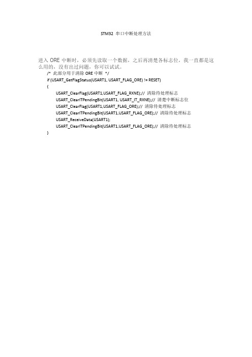
调试发现是串口中断硬件 BUG:
1. USART_ITConfig(USART1, USART_IT_RXNE, ENABLE);使能了接收中断,那么 ORE 中断也同 时被开启了。
2. ORE 中断只能使用 USART_GetFlagStatus(USART1, USART_FLAG_ORE) 读到(没有使 能 USART_IT_ERR 中断时) 解决办法:
4.找资料 STM32F10x 微控制器参考手册(2009 年 12 月第 10 版)P541 发现如下说明:
也就是说只要接收中断打开,即 RXNEIE 设置为 1,那么 ORE 中断也自动打开了。 可是 USART_GetITStatus(USART1, USART_IT_ORE )== RESET!!!! 找到 USART_GetITStatus(USART1, USART_IT_RXNE)函数,发现只有当 USART_IT_ERR 中断使 能时,才能读到 ORE 中断。 在这里要指出这个 BUG:产生 ORE 中断了,但使用 USART_GetITStatus()函数却无法读到这个中断被 SET 起来!
}
2.为什么会一直跑到接收中断? 断点之后发现(USART_GetITStatus(USART1, USART_IT_RXNE)==RESET 的,也就是说没有数据 接收到也进了中断,而且在 USART 配置中我也只打开了接收中断!没有数据送过来应该是不可能进入中断 的!
3.响应了什么中断? 我想通过函数(USART_GetITStatus()把所有中断状态都读出来,但失败了,USART_IT_XXX 所有中断 状态都是 RESET!也就是说没有中断也进入到这个中断服务程序来了!?
qt串口通信c语言代码
qt串口通信c语言代码
引言概述:
QT串口通信是一种基于C语言的编程技术,它可以实现计算机与外部设备之间的数据交互。
本文将从五个大点出发,详细阐述QT串口通信的C语言代码实现。
正文内容:
1. 串口通信的基本原理
1.1 串口通信的定义和作用
1.2 串口通信的工作原理
1.3 串口通信的数据传输方式
2. QT串口通信的C语言代码实现
2.1 QT串口通信的环境搭建
2.2 QT串口通信的代码编写
2.3 QT串口通信的数据收发处理
3. QT串口通信的常见问题与解决方法
3.1 串口通信的波特率设置问题
3.2 数据传输的校验与校验位设置问题
3.3 数据的发送与接收缓冲区处理问题
4. QT串口通信的扩展功能
4.1 串口通信的多线程处理
4.2 串口通信的数据转换与解析
4.3 串口通信的错误处理与异常情况处理
5. QT串口通信的应用实例
5.1 串口通信在嵌入式系统中的应用
5.2 串口通信在数据采集与监控系统中的应用
5.3 串口通信在机器人控制系统中的应用
总结:
通过本文的阐述,我们了解了QT串口通信的C语言代码实现。
首先,我们介绍了串口通信的基本原理,包括定义和作用、工作原理以及数据传输方式。
然后,我们详细讲解了QT串口通信的C语言代码实现,包括环境搭建、代码编写和数据收发处理。
接着,我们列举了一些常见问题,并提供了解决方法。
此外,我们还介绍了QT串口通信的扩展功能和应用实例,展示了其在不同领域的应用前景。
通过学习和实践,我们可以更好地掌握QT串口通信的C语言代码编写技巧,为实际应用提供有力支持。
serialport串口收发原理与实现
serialport串口收发原理与实现一、概述SerialPort是C#中用于串行通信的一种常见方式,它允许应用程序与硬件设备进行交互。
串行通信是一种通过串行数据线传输数据的方式,常见于计算机与外部设备的通信,如打印机、扫描仪和传感器等。
本篇文章将详细介绍SerialPort串口收发原理与实现。
二、串口通信基础串行通信是一种按位传输的方式,数据按位(一个字节)逐个传输,每一位数据占据一个时间槽,这种方式使得数据传输速率相对较低,但具有简单、成本低、易实现的优点。
在串行通信中,数据传输方向通常分为单工、半双工和全双工。
单工通信只能单向传输数据,半双工通信则允许数据在两个方向上传输,但同一时刻只允许一个方向上的数据传输。
全双工通信则允许数据在两个方向上同时传输,但需要使用两根数据线。
三、SerialPort类介绍SerialPort类是System.IO.Ports命名空间下的一个重要组成部分,它提供了串行通信的功能。
SerialPort类的主要属性包括端口号、波特率、数据位、停止位、奇偶校验等。
通过这些属性,我们可以配置串口以适应不同的通信需求。
四、SerialPort使用示例下面是一个简单的SerialPort使用示例:```csharpusing System.IO.Ports;// 创建一个新的SerialPort对象SerialPort serialPort = new SerialPort("COM1", 9600, Parity.None, 8, StopBits.One);// 打开串口serialPort.Open();// 发送数据serialPort.Write("Hello, world!");// 接收数据string receivedData = serialPort.ReadLine();// 关闭串口serialPort.Close();```这个示例展示了如何打开一个串口,发送一条消息,接收一条消息,然后关闭串口。
基于2取2架构的一种串口通信方法

基于2取2架构的一种串口通信方法摘要:介绍一种基于2取2架构的通信方法,采用直连串口作为双CPU通道间2取2通信介质。
CPU通道的任务区分为2oo2任务和非2oo2任务,当需要进行双通道通信时,非2oo2任务在发送消息时会动态决策出一个优先级,打包数据放入消息队列,并通知2oo2任务。
2oo2任务模块根据消息优先级决定处理消息的先后顺序。
数据均先发送给2oo2任务模块,2oo2任务模块可对消息统一进行编号、处理、收发、校验。
本文在数据收发过程中采用动态优先级、滑动窗口确认、数据校验、超时机制相结合的方式,保证了高实时性任务消息被优先处理,保证了双通道交互数据的正确性和及时性。
关键词:2取2;串口通信;滑动窗口;双通道交互Abstract:Introduce a communication method based on 2oo2 architecture, using a direct serial port as the 2oo2 communication medium between dual CPU channels. The tasks of the CPU channel arepided into 2oo2 task and non 2oo2 task. When dual channel communication is required, non 2oo2 task will dynamically decide a priority when sending messages, package data into the message queue, and notify 2oo2 task. The 2oo2 task module determines the order in which messages are processed based on their priority. The data arefirst sent to the 2oo2 task module, which can uniformly number, process, send and receive, and verify messages. This article adopts a combination of dynamic priority, sliding window confirmation, data verification, and timeout mechanism in the process of datatransmission and reception, ensuring that high real-time task messages are prioritized for processing, and ensuring the correctness and timeliness of dual channel interactive data.Key words:2oo2; Serial communication; Sliding window; Dual channel interaction1背景介绍在轨道交通控制领域中,安全性与可靠性是其两个重要的指标,2取2组合-故障安全架构是轨旁及车载等高安全产品中较多采用的一种安全架构。
- 1、下载文档前请自行甄别文档内容的完整性,平台不提供额外的编辑、内容补充、找答案等附加服务。
- 2、"仅部分预览"的文档,不可在线预览部分如存在完整性等问题,可反馈申请退款(可完整预览的文档不适用该条件!)。
- 3、如文档侵犯您的权益,请联系客服反馈,我们会尽快为您处理(人工客服工作时间:9:00-18:30)。
g的串口通讯
通过串口,可以读写,双向通讯。
系统范例
学习系统自带的范 例:
File-examples
关键语句分析
引用库:
import processing.serial.*; Serial myPort; String portName = Serial.list()[0]; myPort = new Serial(this, portName, 9600);
练习:
基础:做一个文字型的电子钟; 进阶:做一个文字加现状的电子钟。
范例1中arduino的代码
int switchPin = 4; // Switch connected to pin 4 void setup() { pinMode(switchPin, INPUT); // Set pin 0 as an input Serial.begin(9600); } void loop() { if (digitalRead(switchPin) == HIGH) { // If switch is ON, Serial.print(1, BYTE); // send 1 to Processing } else { // If the switch is not ON, Serial.print(0, BYTE); // send 0 to Processing } delay(100); // Wait 100 milliseconds }
定义变量
连接指定串口
关键语句分析
判断串口是否有数据
myPort.available() > 0 val = myPort.read(); myPort.write('H');
获取串口数据
输出串口数据
范例1:
import processing.serial.*; Serial myPort; // Create object from Serial class int val; // Data received from the serial port void setup() { size(200, 200); String portName = Serial.list()[0]; myPort = new Serial(this, portName, 9600); } void draw() { if ( myPort.available() > 0) { // If data is available, val = myPort.read(); // read it and store it in val } background(255); // Set background to white if (val == 0) { // If the serial value is 0, fill(0); // set fill to black } else { // If the serial value is not 0, fill(204); // set fill to light gray } rect(50, 50, 100, 100); }