卡斯柯VPI系统手册V1[1].0
Shimadzu VP系列HPLC系统控制器SCL-10A VP说明书

SCL-10A VP System Controller Advanced operationFunction keys and detailed help information(with valid parameter ranges) streamlineparameter setup and instrument operation.Time programs are easily created for precisecomponent control.The graphical user interface rapidlycreates and edits gradient curves for VPSeries solvent delivery units (LC-10AD VPand 10AT VP).Simple mode for routine analysesOperate your isocratic system with asimplified parameter setup. Enter pumpflow rate, detector wavelength, columnoven temperature and autoinjectorbatch schedule parameters.Advanced mode for full controlThe SCL-10A VP’s advanced mode accessesfull VP Series capability. All operationalparameters are controlled by the SCL-10A VP.For autoinjector pretreatment programming,select either simple mode (Quick-pret) orfull mode (Pret-prog).Custom displayFor fast, easy operation, tailor the menuoptions to your requirements.Printed in Japan 3295-05304-30ATDThe contents of this catalog are subject to change without notice.YourInternational Resource for HPLC Validation and ProductivityOptions for SCL-10A VPSpecifications: SCL-10A VP (Cat. No. 228-34350-xx)DisplayFloppy Disk DriveInput/Output TerminalsPossible Component Connection(Parameter setting files )Analysis file Time programFraction collector file Time programBacklit LCD display (320 240 dots )Double sided high density track, Disk: 2HD External start input (MAN. INJ. in ): 1Error input (ALARM IN ): 3Output (EVENT1,2,3,4): 4External power switch control (AC REMOTE ): 1Optical Link (OPT LINK ): 1 (for Chromatopac )RS-232C: 1 (for PC )Remote Signal: 8 (for LC-10A VP /10A module control )Solvent delivery unit: max. 3Autoinjector: 1Column Oven: 1Detectors: max. 2Fraction Collector: 1Sub-controller or valve interface: 12 or 6 position valve: 2 (via Sub-controller or valve interface )Solenoid valve unit: 1 (via Sub-controller or solvent delivery unit )He degassing unit: (via Sub-controller or solvent delivery unit )20 files (parameters, time programs )Total 400 steps, 0.01 9999.9 min, 10 files (parameters, time programs )Total 100 steps, 0.33 9999.9 min,For communication with PC via SCSI interface.Provides 4 additional fiber optic ports.To acquire one detector analog signal. Max 2 boards can be installed.Serial communication port to Chromatopac via RS-232C cable or via Optical fiber cable. Requires a cable separately.228-34359-91228-23517-91223-04202-91223-02983-91102 steps 20 files, 250 byte/file Isocratic, High pressure gradient, Low pressure gradient, Constant pressure delivery Flow rate, Pressure, Concentration, Max.pressure, Min. pressure, Linear, Step,Exponential function (all multi-level )Sample injection volume, No. of repetitions ofanalyses, Analysis time or analysis file No., Sample pretreatment file No., Fraction collector file No.Oven temperatureMaximum temperature Detection wavelength, Range, Time constant, Lampswitching, Wavelength scanning conditions, etc.Scan parameters, Peak detectionparameters, Analytical conditions, etc.Memory check, Max./Min. Pressure limits,Oven temperature upper limit, Lamp current,Motor rotation, etc., abnormality check 260W 420D 140H , approx. 6 4 35228-34350-91 100 120V , 320VA, 50/60Hz 228-34350-92 100 120V , 320VA, 50/60Hz 228-34350-38 220 240V , 320VA, 50/60HzAutoinjector sequence file or analysis sequence fileAutoinjector SamplePretreatment file(Solvent delivery unit control )Control modeSelectable parametersGradient profile(Autoinjector control )Selectable Parameters(Column oven control )Selectable Parameters(Detector control )Selectable Parameters(Fraction collector control )Selectable ParametersSelf diagnostics,Safety featuresDimensions, weightAmbient temperature range Power requirementsSCSI optionExpansion Board, PC-4A/D Board, PC-55N RS-232C/Optical Link Interface, PC-56NSHIMADZU CORPORATION. International Marketing Division3. Kanda-Nishikicho 1-chome, Chiyoda-ku, Tokyo 101-8448, Japan Phone: 81(3)3219-5641 Fax. 81(3)3219-5710Cable Add.:SHIMADZU TOKYOSHIMADZU SCIENTIFIC INSTRUMENTS, INC.7102 Riverwood Drive, Columbia, Maryland 21046, U.S.A.Phone: 1(410)381-1227 Fax. 1(410)381-1222 Toll Free: 1(800)477-1227SHIMADZU DEUTSCHLAND GmbHAlbert-Hahn-Strasse 6-10, D-47269 Duisburg, F.R. Germany Phone: 49(203)7687-0 Fax. 49(203)766625SHIMADZU (ASIA PACIFIC) PTE LTD.16 Science Park Drive #01-01 Singapore Science Park, Singapore 118227, Republic of Singapore Phone: 65-778 6280 Fax. 65-779 2935SHIMADZU SCIENTIFIC INSTRUMENTS (OCEANIA) PTY. LTD.Units F, 10-16 South Street Rydalmere N.S.W. 2116, Australia Phone: 61(2)9684-4200 Fax. 61(2)9684-4055SHIMADZU DO BRASIL COMERCIO LTDA.Rua Cenno Sbrighi, 25, Agua Branca, Sao Paulo, CEP 05036-010, BRAZIL Phone: (55)11-3611-1688 Fax. (55)11-3611-2209SHIMADZU (HONG KONG) LIMITEDSuite 1028 Ocean Center, Harbour City, Tsim Sha Tsui, Kowloon HONG KONG Phone: (852)2375-4979 Fax. (852)2199-7438Overseas OfficesIstanbul, Beijing, Shanghai, Guangzhou, Shenyang, Chengdu, MoscowURL 。
VP-iTC操作指南
VP-iTC操作指南VP-iTC操作指南1.简介1.1 概述●本文档是VP-iTC操作的详细指南,旨在帮助用户熟悉和正确使用VP-iTC系统。
1.2 目的●本操作指南旨在提供有关如何使用VP-iTC系统的详细说明,包括系统功能、操作步骤和常见问题解答。
1.3 受众●本操作指南适用于VP-iTC系统的用户,包括管理员和普通用户。
2.系统安装和配置2.1 硬件要求●阐述VP-iTC系统所需的硬件要求,例如服务器规格和网络环境。
2.2 软件安装●详细说明如何安装VP-iTC系统,并提供安装步骤和注意事项。
2.3 数据库配置●解释如何配置VP-iTC系统的数据库,包括数据库类型、连接设置和授权访问。
3.用户管理3.1 添加用户●说明如何在VP-iTC系统中添加新用户,包括设置用户名、密码和用户权限。
3.2 用户权限管理●解释如何管理用户权限,包括分配和撤销用户的特定操作权限。
3.3 修改用户信息●提供指导,教用户如何修改已有用户的个人信息和密码。
4.数据录入和管理4.1 新建数据●介绍如何在VP-iTC系统中创建新的数据记录,包括填写必要字段和选择适当的数据类型。
4.2 编辑和查看数据●解释如何编辑和查看已存在的数据记录,包括修改字段值和搜索数据。
4.3 数据导入和导出●详细说明如何将外部数据导入VP-iTC系统,并解释如何导出系统中的数据。
5.数据分析5.1 数据统计●介绍如何使用VP-iTC系统进行数据统计和报表,包括选择统计指标和配置统计参数。
5.2 数据可视化●解释如何使用VP-iTC系统的可视化功能,将数据以图表或图形方式展示,便于分析和理解。
5.3 数据筛选和排序●提供指导,教用户如何筛选和排序数据,以便更好地满足特定需求。
6.常见问题解答●提供常见问题解答,包括系统常见错误、故障和操作问题的解决方案。
附件:●附件1:VP-iTC系统安装包●附件2:数据库配置示例法律名词及注释:●法律名词1:具体解释或定义●法律名词2:具体解释或定义。
Carrier i-Vu系统用户指南说明书

Contents
What is i-Vu® Pro for Life Sciences? ......................................................................................................................... 1
i-Vu® Pro v8.0 Life Sciences Best Practices Guide
Carrier Proprietary and Confidential 2
CARRIER CORPORATION ©2021 All rights reserved
Life Sciences best practices
Upgrading from a previous version of i-Vu® Pro
To convert a customer’s license from a previous version of i-Vu® Pro (CIV-OPNPR) or i-Vu® Pro Unlimited (CIVOPNPRUL) to i-Vu® Pro for Life Sciences v8.0 (CIV-OPNPRLS), contact your Carrier Regional Sales Manager. For general upgrade instructions see the i-Vu® Pro v8.0 Upgrade Guide. Follow the steps below to ensure your system’s previously validated drivers and programs are successfully transferred to the new, upgraded system.
卡斯柯信号系统(Urbalis888)平移运行图原理及操作要点

卡斯柯信号系统(Urbalis888)平移运行图原理及操作要点发布时间:2021-05-25T09:48:52.430Z 来源:《基层建设》2020年第30期作者:毛慧明匡亮[导读] 摘要:平移运行图是一种非常方便的延长运营时间的手段,通过平移运行图可以高效便捷的匹配节假日的客流情况,不用额外编制新的运行图就可以让列车按照时刻表功能有序运行。
武汉地铁运营有限公司湖北武汉 430000摘要:平移运行图是一种非常方便的延长运营时间的手段,通过平移运行图可以高效便捷的匹配节假日的客流情况,不用额外编制新的运行图就可以让列车按照时刻表功能有序运行。
本文通过详细讲解卡斯柯信号系统(Urbalis888)平移运行图原理及操作要点,希望能够对同行以及对轨道交通行业的发展起到一定对理论指导作用。
关键词:卡斯柯信号系统;调整;运行图;平移一、平移运行图原理图1.1为2号线大小交路运行图示意图,其中大交路周转时间为190分钟,小交路周转时间为137分钟,将图1.1的运行图向后平移190分钟可以得到图1.2,此时大交路列车车次的服务号不变,序号发生改变,小交路列车车次的服务号和序号都会发生改变,比如未平移运行图时,11:10,00107次列车在天河机场下行站台,00207次列车在金银潭下行站台,此时将运行图向后平移190分钟,天河机场下行站台的00107次列车就改为了00105次列车,金银潭下行站台的00207次列车改为了00305次列车。
(图1.2)2号线大小交路运行图平移“+190min”后示意图同理可以推理出若将运行图向后平移1个小交路的周转时间“+135”分钟,此时小交路列车车次的服务号不变,序号发生改变,大交路列车车次的服务号和序号都会发生改变。
备注:此文中的大交路为天河机场至光谷火车站,小交路为金银潭至光谷火车站。
若2号线采用双小交路运营时(天河机场至佛祖岭、金银潭至光谷火车站),运行图平移规律也是一样的。
SIMATIC Visualization Architect系统手册
危险 表示如果不采取相应的小心措施,将会导致死亡或者严重的人身伤害。
警告 表示如果不采取相应的小心措施,可能导致死亡或者严重的人身伤害。
小心 表示如果不采取相应的小心措施,可能导致轻微的人身伤害。
注意 表示如果不采取相应的小心措施,可能导致财产损失。
当出现多个危险等级的情况下,每次总是使用最高等级的警告提示。如果在某个警告提示中带有警告可能导致人身 伤害的警告三角,则可能在该警告提示中另外还附带有可能导致财产损失的警告。
安全性信息
1
基本知识
2
SIMATIC
安装
3
TIA-Portal
元素和基本设置
4
SIMATIC Visualization Architect
使用 SiVArc
5
系统手册
使用 SiVArc 表达式
6
参考
7
SiVArc 消息
8
在线帮助打印输出 07/2016
在线帮助打印输出
法律资讯 警告提示系统ቤተ መጻሕፍቲ ባይዱ
为了您的人身安全以及避免财产损失,必须注意本手册中的提示。人身安全的提示用一个警告三角表示,仅与财产 损失有关的提示不带警告三角。警告提示根据危险等级由高到低如下表示。
2.3
关于使用 SiVArc 的基础知识..........................................................................................17
2.4
支持的设备......................................................................................................................21
TransPort主模式IPsec IKEv1 VPN使用手册说明书

Quick Note 061Main Mode IPsec IKEv1 VPN from TransPort to StrongSwan using Preshared key22 August 20171Introduction (3)1.1Introduction (3)1.2Network Diagram (3)1.3Outline (4)1.4Assumptions (4)1.5Corrections (4)1.6Version (4)2TransPort Configuration (5)2.1Local Ethernet Interface Configuration (5)2.1WAN interface configuration (6)2.1Tunnel Configuration (7)2.1.1Phase 1 Settings (7)2.1.2Phase 2 settings (8)2.2Configure users (10)3StrongSwan Configuration (11)3.1Configure Ethernet Interfaces (11)3.1.1WAN Interface (11)3.1.2Local Interface (11)3.2Install StrongSwan (11)3.3Configure StrongSwan (13)3.3.1IPsec VPN Configuration (13)3.4Start/Restart the StrongSwan IPsec daemon (16)4Check Tunnel Status (17)4.1Digi TransPort (17)4.2StrongSwan (18)5Testing (19)5.1TransPort side (19)5.2StrongSwan side (19)6TransPort Configuration (20)1.1IntroductionThis document describes how to configure a VPN IPsec tunnel between a Digi TransPort WR to and a StrongSwan server using Main Mode, IKEv1 and pre-shared key authentication.1.2Network DiagramTransPort WR RouterStrongSwan1.3OutlineThis guide details the steps involved in configuring a Digi TransPort router to act as an IPsec VPN client to a StrongSwan appliance configured as an IPsec VPN server using Main Mode, IKEv1 and pre-shared key authentication. This example as sumes that both equipment’s are not behind a NAT box.1.4AssumptionsThis guide has been written for use by technically competent personnel with a good understanding of the communications technologies used in the product and of the requirements for their specific application. It also assumes a basic ability to access and navigate a Digi TransPort router and configure it with basic routing functionsThis application note applies to:Model: Digi TransPort WR11/21/31/41/44Firmware versions:WR21: 5.2.17.10 and laterConfiguration: This document assumes that the devices are set to their factory default configurations. Most configuration commands are shown only if they differ from the factory default. Please note: This application note has been specifically rewritten for the specified firmware versions and later but will work on earlier versions of firmware. Please contact ********************* if your require assistance in upgrading the firmware of the TransPort WR routers.1.5CorrectionsRequests for corrections or amendments to this application note are welcome and should be addressed to: ********************* Requests for new application notes can be sent to the same address.1.6Version2.1Local Ethernet Interface ConfigurationNavigate to Configuration – Network > Interfaces > Ethernet > Ethernet 02.1WAN interface configurationIn this example, the mobile interface will be used as the WAN interface on which the IPsec tunnel will be established.Navigate to:Configuration – Network > Interfaces > MobilePlease note: If required, enter a SIM PIN and Username/Password for this SIM card and APN.2.1Tunnel ConfigurationOpen a web browser to the IP address of the TransPort WR21 router. 2.1.1Phase 1 SettingsNavigate to:Configuration – Network > Virtual Private Network (VPN) >IKE > IKE 02.1.2Phase 2 settingsNavigate to:Configuration – Network > Virtual Private Network (VPN) > IPsec > IPsec 0 – 9 > IPsec 0Click Apply2.2Configure usersNavigate to Configuration - Security > Users > User 0-9 > User 9Here the pre-shared key is configured using the WAN IP address of the StrongSwan. The username value should therefore match the Peer ID set in the IPsec configuration above:3.1Configure Ethernet Interfaces3.1.1WAN InterfaceConfigure the WAN interface for the StrongSwan Server. In this example, the Ethernet interface used for WAN is called ens33root@ubuntu:/home/digi# ifconfig ens33 192.168.1.118root@ubuntu:/home/digi# ifconfig ens33 netmask 255.255.255.0root@ubuntu:/home/digi# route add default gw 192.168.1.254 ens333.1.2Local InterfaceConfigure the Local interface for the StrongSwan Server. In this example, the Ethernet interface used for LAN is called enx00249b09ef56root@ubuntu:/home/digi# ifconfig enx00249b09ef56 100.10.10.2root@ubuntu:/home/digi# ifconfig enx00249b09ef56 netmask 255.255.255.03.2Install StrongSwanDepending on the Linux distribution, the installation of StrongSwan might defer. In this document, Ubuntu is used. Please refer to for further installation instructions. The easiest way t o install StrongSwan is via the “apt-get install strongswan” CLI command:digi@ubuntu:~$ sudo apt-get install strongswanReading package lists... DoneBuilding dependency treeReading state information... DoneThe following additional packages will be installed:libstrongswan libstrongswan-standard-plugins strongswan-charonstrongswan-libcharon strongswan-starterSuggested packages:libstrongswan-extra-plugins libcharon-extra-pluginsThe following NEW packages will be installed:libstrongswan libstrongswan-standard-plugins strongswan strongswan-charon strongswan-libcharon strongswan-starter0 upgraded, 6 newly installed, 0 to remove and 59 not upgraded.Need to get 3,731 kB of archives.After this operation, 16.1 MB of additional disk space will be used.Do you want to continue? [Y/n] yGet:1 /ubuntu xenial-updates/main amd64 libstrongswan amd64 5.3.5-1ubuntu3.4 [1,398 kB]Get:2 /ubuntu xenial-updates/main amd64 strongswan-libcharon amd64 5.3.5-1ubuntu3.4 [1,241 kB]Get:3 /ubuntu xenial-updates/main amd64 strongswan-starter amd64 5.3.5-1ubuntu3.4 [742 kB]Get:4 /ubuntu xenial-updates/main amd64 strongswan-charon amd64 5.3.5-1ubuntu3.4 [55.6 kB]Get:5 /ubuntu xenial-updates/main amd64libstrongswan-standard-plugins amd64 5.3.5-1ubuntu3.4 [267 kB]Get:6 /ubuntu xenial-updates/main amd64strongswan all 5.3.5-1ubuntu3.4 [27.1 kB]Fetched 3,731 kB in 12s (307 kB/s) Preconfiguring packages ...Selecting previously unselected package libstrongswan.(Reading database ... 175214 files and directories currently installed.) Preparing to unpack .../libstrongswan_5.3.5-1ubuntu3.4_amd64.deb ...Unpacking libstrongswan (5.3.5-1ubuntu3.4) ...Selecting previously unselected package strongswan-libcharon.Preparing to unpack .../strongswan-libcharon_5.3.5-1ubuntu3.4_amd64.deb ... Unpacking strongswan-libcharon (5.3.5-1ubuntu3.4) ...Selecting previously unselected package strongswan-starter.Preparing to unpack .../strongswan-starter_5.3.5-1ubuntu3.4_amd64.deb ... Unpacking strongswan-starter (5.3.5-1ubuntu3.4) ...Selecting previously unselected package strongswan-charon.Preparing to unpack .../strongswan-charon_5.3.5-1ubuntu3.4_amd64.deb ... Unpacking strongswan-charon (5.3.5-1ubuntu3.4) ...Selecting previously unselected package libstrongswan-standard-plugins. Preparing to unpack .../libstrongswan-standard-plugins_5.3.5-1ubuntu3.4_amd64.deb ...Unpacking libstrongswan-standard-plugins (5.3.5-1ubuntu3.4) ...Selecting previously unselected package strongswan.Preparing to unpack .../strongswan_5.3.5-1ubuntu3.4_all.deb ...Unpacking strongswan (5.3.5-1ubuntu3.4) ...Processing triggers for man-db (2.7.5-1) ...Setting up libstrongswan (5.3.5-1ubuntu3.4) ...Setting up strongswan-libcharon (5.3.5-1ubuntu3.4) ...Setting up strongswan-starter (5.3.5-1ubuntu3.4) ...Setting up strongswan-charon (5.3.5-1ubuntu3.4) ...Setting up libstrongswan-standard-plugins (5.3.5-1ubuntu3.4) ...Setting up strongswan (5.3.5-1ubuntu3.4) ...Please note: All commands have to be used in elevated or super user mode. For ease of configuration, this document will use the root user (not recommended). In most case, using “sudo” in front of each commands will provide the expected result.3.3Configure StrongSwan3.3.1IPsec VPN ConfigurationThe IPsec configuration of StrongsWan is done via 2 main files (when using pre-shared keys as in this example):-ipsec.conf : Used for Phase 1 (IKE) and Phase 2 IPsec configuration-ipsec.secrets : Used for pre-shared keysIn this example, the following Phase 1 settings will be used:-AES (128 bit)-SHA 1-MODP Group 2-Main ModeIn this example, the following Phase 2 settings will be used:-AES (128 bit)-SHA 1-No PFS-ID Types : IPv4-Preshared Keys3.3.1.1ipsec.confEdit the ipsec.conf file using a text editor such as vi: config setupconn %defaultikelifetime=60mkeylife=20mrekeymargin=3mkeyingtries=%foreverkeyexchange=ikev1authby=secretconn peer1-peer2left=192.168.1.118leftsubnet=100.10.10.0/24leftfirewall=yesright=%anyrightallowany=yesrightsubnet=10.0.0.0/24auto=startcloseaction=restartike=aes128-sha1-modp1024esp=aes128-sha1type=tunnelkeyingtries=%forevertype :wq to save and close3.3.1.2ipsec.secretsEdit the ipsec.secrets file using a text editor such as vi:192.168.1.118 : PSK "digidigi"192.168.1.23 : PSK "digidigi"type :wq to save and close3.4Start/Restart the StrongSwan IPsec daemonOnce the files are modified, the changes will only take effect after reloading the StrongSwan daemon. To do so, issue the following command:root@ubuntu:/home/digi# ipsec restartStopping strongSwan IPsec...Starting strongSwan 5.3.5 IPsec [starter]...4.1Digi TransPortNavigate to Management – Connections > Virtual Private Networking (VPN) > IPsec > IPsec Tunnels > IPsec Tunnels 0 – 9 > IPsec Tunnels 0-9Via CLI:sastatCommand: sastatCommand resultIPsec SAs (total:1). Eroute 0 -> 49Outbound V1 SAsSPI Eroute Peer IP Rem. subnet Loc. subnet TTL KBytes Left VIPc3b444ae 0 192.168.1.118 100.10.10.0/24 10.0.0.0/24 28648 0 N/AInbound V1 SAsSPI Eroute Peer IP Rem. subnet Loc. subnet TTL KBytes Left VIP6eb46719 0 192.168.1.118 100.10.10.0/24 10.0.0.0/24 28648 0 N/AOutbound V2 SAsList EmptyInbound V2 SAsList EmptyOK4.2StrongSwanroot@ubuntu:/home/digi# ipsec statusallStatus of IKE charon daemon (strongSwan 5.3.5, Linux 4.10.0-28-generic,x86_64):uptime: 29 seconds, since Aug 22 06:25:17 2017malloc: sbrk 1486848, mmap 0, used 344640, free 1142208worker threads: 11 of 16 idle, 5/0/0/0 working, job queue: 0/0/0/0, scheduled: 3loaded plugins: charon test-vectors aes rc2 sha1 sha2 md4 md5 random nonce x509 revocation constraints pubkey pkcs1 pkcs7 pkcs8 pkcs12 pgp dnskey sshkey pem openssl fips-prf gmp agent xcbc hmac gcm attr kernel-netlink resolve socket-default connmark stroke updownListening IP addresses:192.168.1.118100.10.10.2Connections:peer1-peer2: 192.168.1.118...%any,0.0.0.0/0,::/0 IKEv1peer1-peer2: local: [192.168.1.118] uses pre-shared key authenticationpeer1-peer2: remote: uses pre-shared key authenticationpeer1-peer2: child: 100.10.10.0/24 === 10.0.0.0/24 TUNNELSecurity Associations (1 up, 0 connecting):peer1-peer2[1]: ESTABLISHED 22 seconds ago,192.168.1.118[192.168.1.118]...192.168.1.23[192.168.1.23]peer1-peer2[1]: IKEv1 SPIs: 6eb06982e84e8679_i 208d286522e19369_r*, pre-shared key reauthentication in 54 minutespeer1-peer2[1]: IKE proposal:AES_CBC_128/HMAC_SHA1_96/PRF_HMAC_SHA1/MODP_1024peer1-peer2{1}: INSTALLED, TUNNEL, reqid 1, ESP SPIs: cc5e3c54_i 6eb4671a_o peer1-peer2{1}: AES_CBC_128/HMAC_SHA1_96, 0 bytes_i, 0 bytes_o, rekeying in 15 minutespeer1-peer2{1}: 100.10.10.0/24 === 10.0.0.0/24To simply test the tunnel, generate a ping from each side of the tunnel and ping the remote end’s ethernet interface.5.1TransPort sideCommand: ping 100.10.10.2 –e0Command resultPinging Addr [100.10.10.2]sent PING # 1PING receipt # 1 : response time 0.00 secondsIface: PPP 1Ping StatisticsSent : 1Received : 1Success : 100 %Average RTT : 0.00 secondsOK5.2StrongSwan sideroot@ubuntu:/home/digi# ping 10.0.0.1PING 10.0.0.1 (10.0.0.1) 56(84) bytes of data.64 bytes from 10.0.0.1: icmp_seq=1 ttl=250 time=2.30 ms64 bytes from 10.0.0.1: icmp_seq=2 ttl=250 time=1.30 ms64 bytes from 10.0.0.1: icmp_seq=3 ttl=250 time=1.56 ms64 bytes from 10.0.0.1: icmp_seq=4 ttl=250 time=1.28 ms64 bytes from 10.0.0.1: icmp_seq=5 ttl=250 time=1.35 ms64 bytes from 10.0.0.1: icmp_seq=6 ttl=250 time=1.38 ms^C--- 10.0.0.1 ping statistics ---6 packets transmitted, 6 received, 0% packet loss, time 5010msrtt min/avg/max/mdev = 1.287/1.532/2.304/0.358 mseth 0 IPaddr "10.0.0.1"addp 0 enable ONlapb 0 ans OFFlapb 0 tinact 120lapb 1 tinact 120lapb 3 dtemode 0lapb 4 dtemode 0lapb 5 dtemode 0lapb 6 dtemode 0ip 0 cidr ONdef_route 0 ll_ent "ppp"def_route 0 ll_add 1eroute 0 descr "StrongSwan"eroute 0 peerip "192.168.1.118" eroute 0 peerid "192.168.1.118" eroute 0 ourid "192.168.1.23" eroute 0 ouridtype 3eroute 0 locip "10.0.0.0"eroute 0 locmsk "255.255.255.0" eroute 0 locipifadd 1eroute 0 remip "100.10.10.0" eroute 0 remmsk "255.255.255.0" eroute 0 ESPauth "SHA1"eroute 0 ESPenc "AES"eroute 0 authmeth "PRESHARED" eroute 0 nosa "TRY"eroute 0 autosa 2eroute 0 enckeybits 128dhcp 0 respdelms 500dhcp 0 mask "255.255.255.0"dhcp 0 gateway "192.168.1.1"dhcp 0 DNS "192.168.1.1"sntp 0 server "" ppp 0 timeout 300ppp 1 name "W-WAN"ppp 1 phonenum "*98*1#"ppp 1 username "username"ppp 1 epassword "KD5lSVJDVVg=" ppp 1 IPaddr "0.0.0.0"ppp 1 timeout 0ppp 1 do_nat 2ppp 1 ipsec 1ppp 1 use_modem 1ppp 1 aodion 1ppp 1 autoassert 1ppp 1 r_chap OFFppp 3 defpak 16ppp 4 defpak 16web 0 prelogin_info ONike 0 encalg "AES"ike 0 keybits 128ike 0 authalg "SHA1"ike 0 ikegroup 2ike 0 noresp ONike 0 deblevel 4ike 0 debug ONana 0 anon ONana 0 l2on OFFana 0 l3on OFFana 0 xoton OFFana 0 lapdon 0ana 0 lapbon 0ana 0 ikeon ONana 0 logsize 45cmd 0 unitid "ss%s>"cmd 0 cmdnua "99"cmd 0 hostname "digi.router"cmd 0 asyled_mode 2cmd 0 tremto 1200cmd 0 rcihttp ONuser 0 access 0user 1 name "username"user 1 epassword "KD5lSVJDVVg="user 1 access 0user 2 access 0user 3 access 0user 4 access 0user 5 access 0user 6 access 0user 7 access 0user 8 access 0user 9 name "192.168.1.118"user 9 epassword "PDZxU0FFQFU="user 9 access 4local 0 transaccess 2sslsvr 0 certfile "cert01.pem"sslsvr 0 keyfile "privrsa.pem"ssh 0 hostkey1 "privSSH.pem"ssh 0 nb_listen 5ssh 0 v1 OFFcloud 0 clientconn ONcloud 0 ssl ONOKPage | 21。
SVX无线系统用户指南说明书

SVX Wireless SystemOnline user guide for SVX wireless system. Version: 1.0 (2022-A)Table of ContentsSVX Wireless System3安全事項3快速設定3 Shure SVX 無線系統4接收機4發射機 5系統組件6所有系統 6手持式發射機 6腰包式發射機 6電源6連接到音響系統 7頻道 7腰包增益 7 RF 水平 7靜噪 7電池電量過低指示燈 7顏色標識環 7獲得良好音質7正確放置麥克風 8佩戴頭戴式麥克風 8腰包式傳送器的佩戴 8可提高系統性能的無線使用提示9故障排除9選配附件10備件10 10頻率範圍10澳大利亞無線警告11規格 11SVXWireless System安全事項根據危險程度和損壞嚴重性的不同,使用“警告”和“小心”文字對未正確使用可能導致的後果做出標識。
警告:如果沒有遵循這些警告事項,在操作不正確的情況下可能會導致嚴重的人身傷亡事故。
小心:如果沒有遵循這些警告事項,在操作不正確的情況下可能會導致常見的人身傷害或財產損失。
警告如果有水或其他異物進入設備內部,可能會導致起火或觸電事故。
不要嘗試改裝本產品。
這樣做會導致人身傷害和/或產品故障。
小心不要拆開或改裝本設備,這樣可能會導致故障。
不要用力過大,不要拉扯線纜,否則會損壞線纜。
讓話筒保持乾燥,並避免暴露在極高溫度和濕度環境下。
快速設定Shure SVX 無線系統恭喜您購買了舒爾的 SVX 無線系統。
舒爾專業音響產品能夠提供出色的音響質量,在舞臺上經久耐用,讓您的演出輕鬆自如。
SVX 無線系統可與領夾式、手持式或頭戴式話筒一起使用,適用於演示、卡拉 OK 表演、增氧運動/健身教練或其它需要無線移動功能場合。
接收機KCX4KCX88①電源指示燈②音訊指示燈③無線電頻率密度指示燈④平衡輸出(XLR 接頭)⑤非平衡輸出(6.35 毫米接頭)⑥音訊輸出電平(線路/話筒)切換製⑦頻道選擇旋鈕⑧靜噪旋鈕⑨電源適配器輸入⑩天線發射機①電源按鈕••••••••••② 頻道選擇旋鈕③ 音訊輸入電平(線路/話筒)切換開關④ 電池艙⑤ 發射機增益旋鈕⑥ 皮帶夾⑦ 話筒輸入(CVL 領夾式或 PGA31 頭戴式)⑧ 無線電射頻 (RF) 電平切換開關⑨ 天線⑩ 顏色標識環⑪ 防滾環⑫ 電源 LED 指示燈系統組件所有系統SVX 接收機PS24 電源部件頻道選擇工具2 枚 AA 電池手持式發射機SVX2 手持式話筒發射機話筒底座轉接頭腰包式發射機SVX1 腰包式發射機話筒PG185 領夾式話筒或PG30 頭戴式話筒電源插上電源適配器,將接收機電源打開。
VersiTomic 弹性ACL PCL泡沫系统说明书

VersiTomic flexible ACL/PCL reaming systemPrecise, reproducible placementSimpl e and flexible options to give you versatility in achieving tunnel length, angle, back-wall width andanatomical graft placement VersiTomic ligament reconstruction system VersiTomic flexible reamersVersiTomic Flex drills are designed to enableprecise intra-articular placement and safesocket/tunnel creation with an eccentriccutting f lute head and fl exible puzzle pieceshaft that mitigates potential for damage toperipheral cartilage, bone or soft tissue .Reamers are available in 4.5mm–12.0mmsizes in 0.5mm increments.VersiTomic outside-in depth gauge This easy to use, outside-in depth gauge provides a simple to read and accuratetunnel measurement.VersiTomic starter awlThe VersiTomic starter awl is used to mark the central position of the native ACL and create a pilot hole to ensure accurate exit of the VersiTomic guide pin.Features •Designed to be used through the anteromedialportal to achieve longer femoral tunnelswithout the need to hyperflex the knee.1•45° curvature—aids in directing the flexible pin to preferred tunnel direction.Anteromedial (A/M) portal guidesAchieve longer femoral tunnelswithout the need to hyperflex the knee 1Dam feature All of the VersiTomic A/M guides come with an addedfeature that is designed toreduce fluid flowing out theback of the guide prior topin placement.VersiTomic guide with AccuPin technology Each of the VersiTomic A/M guides has a built-in pin predictor. With a flip of the AccuPin, you can visualize the plane in which the pin should exit the femur.VersiTomic A/M guide, straight curve The straight curve A/M guide allows freedom to place the guide pin exactly where you prefer, and the enhanced spiked distal tip designed to provide a secure grip to mitigate slipping during pin placement and drilling.2VersiTomic offset A/M guides Left (red) and right (green) side specific guides are available with 5mm, 6mm, and 7mm offsetsProduct number DescriptionOrdering informationSports medicineThis document is intended solely for the use of healthcare professionals. A surgeon must always rely on his or her own professional clinical judgment when deciding whether to use a particular product when treating a particular patient. We do not dispense medical advice and recommend that surgeons be trained in the use of any particular product before using it in surgery.Complications are rare. Serious adverse events, some with fatal outcome, associated with the use of bone cements for vertebroplasty, kyphoplasty and sacroplasty include myocardial infarction, cardiac arrest, cerebrovascular accident, pulmonary embolism, and cardiac embolism. Although it is rare, some adverse events have been known to occur up to one year following the procedure.Additional risks exist with the use of bone cement. Please see your health care provider for a complete list of potential risks.The information presented is intended to demonstrate a Stryker product. A surgeon must always refer to the package insert, product label and/or instructions for use, including the instructions for cleaning and sterilization (if applicable), before using any Stryker product. Products may not be available in all markets because product availability is subject to the regulatory and/or medical practices in individual markets. Please contact your Stryker representative if you have questions about the availability of Stryker products in your area.Stryker or its affiliated entities own, use, or have applied for the following trademarks or service marks: AccuPin, Stryker and VersiTomic. All other trademarks are trademarks of their respective owners or holders.The absence of a product, feature, or service name, or logo from this list does not constitute a waiver of Stryker’s trademark or other intellectual property rights concerning that name or logo.LJPVT-B Rev CCopyright © 2019 Stryker StrykerSports Medicine5670 Greenwood Plaza Blvd. Ste. 200Greenwood Village, CO 80111t: 866 596 2022References:1.Steiner and Smart, "Flexible Instruments Outperform Rigid Instruments to Place Anatomic AnteriorCruciate Ligament Femoral Tunnels Without Hyperflexion" Arthroscopy 28(6) 843, 2012.2.Stryker DHFD14484 Rev. A 2019。
VPI型计算机联锁系统
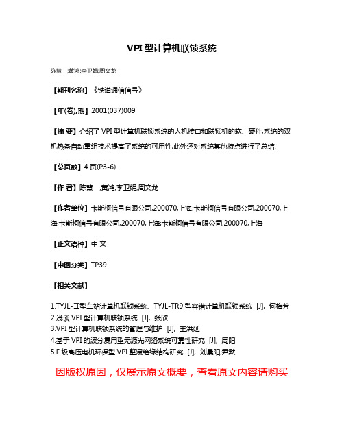
VPI型计算机联锁系统
陈慧;黄鸿;李卫娟;周文龙
【期刊名称】《铁道通信信号》
【年(卷),期】2001(037)009
【摘要】介绍了VPI型计算机联锁系统的人机接口和联锁机的软、硬件,系统的双机热备自动重组技术提高了系统的可用性,此外还对系统其他特点进行了总结.【总页数】4页(P3-6)
【作者】陈慧;黄鸿;李卫娟;周文龙
【作者单位】卡斯柯信号有限公司,200070,上海;卡斯柯信号有限公司,200070,上海;卡斯柯信号有限公司,200070,上海;卡斯柯信号有限公司,200070,上海
【正文语种】中文
【中图分类】TP39
【相关文献】
1.TYJL-Ⅱ型车站计算机联锁系统、TYJL-TR9型容错计算机联锁系统 [J], 何梅芳
2.浅谈VPI型计算机联锁系统 [J], 张欣
3.VPI型计算机联锁系统的管理与维护 [J], 王洪延
4.基于VPI的波分复用型无源光网络系统可靠性研究 [J], 周阳
5.F级高压电机环保型VPI整浸绝缘结构研究 [J], 刘晨阳;尹默
因版权原因,仅展示原文概要,查看原文内容请购买。
Cuinsico卡因斯科伺服-HCSE系列用户手册(V1.00)

IV
— 目 录 —
第 1 章...................................................................................................................................................................................................................1 规格型号..................................................................................................................................................................................................................1
HCSE系列交流伺服 用户手册
(V1.00)
宁波和创电子科技有限公司
I
及注意事项
一、安全事项 ■ 安装前 (1)损伤的伺服驱动器及缺件的伺服驱动器请不要使用,否则有受伤的危险。 (2)请使用B级以上绝缘的电机,否则有触电的危险。 ■ 安装时 (1)请安装在金属等阻燃的物体上并远离可燃物,否则可能引起火警! (2)两个以上伺服驱动器置于同一柜中时,请注意安装位置,保证散热效果。 (3)不能让导线头或螺钉掉入伺服驱动器中,否则可能引起伺服驱动器损坏! ■ 配线时 (1)应由专业电气工程人员施工,否则有触电危险! (2)伺服驱动器和电源之间必须有断路器隔开,否则可能发生火警! (3)接线前请确认电源处于关断状态,否则有触电的危险! (4)接地端子必须可靠接地,否则有触电的危险! (5)不能将输入电源线连接到输出端U、V、W,否则会引起伺服驱动器损坏! (6)确保所用导线线径与所选用驱动器的功率相匹配。 ■ 上电前 (1)请确认电源电压等级是否和伺服驱动器额定电压一致;输入、输出的接线位置是否正确,并注意检查外围电路中是否有短 路现象,所连线路是否紧固,否则可能引起伺服驱动器损坏! (2)伺服驱动器无需进行耐压试验,出厂时产品已经做过此项测试,若用户自行测试可能引起事故! (3)确认所有外围配件是否按照本手册所提供电路正确配线。否则可能引起事故! ■ 上电后 (1)上电后不要打开伺服驱动器,否则有触电危险! (2)不要用湿手触摸伺服驱动器及周边电路,否则有触电危险! (3)不要触摸伺服驱动器端子(含控制端子),否则有触电危险! (4)禁止带电插、拔驱动器上的接插件,否则极易损坏驱动器的内部电路和电机编码器! (5)若需要进行参数辨识,请注意电机旋转中伤人的危险,否则可能引起事故! (6)不宜对伺服驱动器的参数进行极端的调整或变更,否则极易引起机械的剧烈震荡,造成不必要的财产损失! ■ 运行中 (1)请勿触摸散热器及制动电阻以试探温度,否则可能引起灼伤! (2)非专业技术人员请勿在运行中检测伺服驱动器信号,否则可能引起人身伤害或设备损坏! (3)不要采用接触器通断的方法来控制伺服电机的启停,否则使得伺服驱动器内部组件迅速老化,降低驱动器的使用寿命,应 使用指令信号来控制伺服电机的运行。 ■ 维修保养时
Klavis LX-V2 用户手册说明书

SUPPORT & ADDITIONAL INFOThe complete users manual is available on:/supportLX-V2 - Copyright 2019 - Diagonal ElectronicsINSTALLATIONVersions of the Logica XT with a 16-pin connector require a 5V rail in your case, those with a 10-pin connector do not. Ensure that there is enough power left to supply this module. Beware of the orientation; the stripe on the ribbon cable should match a similar stripe for the –12 (minus 12 Volts) indication on your supply board connector. Supply rail Current draw (16-pin) Current draw(10-pin)+12V 0 mA 21 mA -12V 1 mA 1 mA +5V16 mA0 mAR EAD M EF I R S TFUNCTIONS* over 5000 steps memoryUSAGE & PANELTwo sets of functions are offered: simple (left column), and advanced (right column). Switching between sets is done by a quick press of Xtra. A function is selected by the sum of the knob position and the voltage pre-sent at the Mode CV jack. Inv out is always the reverse of Out. Div/2 tog-gles every time Out goes high. You can bring 4 signals (3 jacks and a push-button). Unused jacks are nor-malized or ignored as needed. With S/R.C and D.S&H functions, the input jacks have a specific role indicat-ed respectively in the middle and on the right side of each jack.When the knob+CV setting is full up or full down, Out is forced high or low respectively.The default setting of the Manual but-ton and various advanced timing set-tings can be modified and stored. See the manual for details.。
SIM7000系列_SSL应用指南_V1.00说明书

SIM7000 series_ SSL_ Application Note _V1.00General NotesSIMCom offers this information as a service to its customers, to support application and engineering efforts that use the products designed by SIMCom. The information provided is based upon requirements specifically provided to SIMCom by customers. SIMCom has not undertaken any independent search for additional relevant information, including any information that may be in the customer’s possession. Furthermore, system validation of this product designed by SIMCom within a larger electronic system remains the responsibility of the customer or the customer’s system integrator. All specifications supplied herein are subject to change.CopyrightsThis document contains proprietary technical information which is the property of SIMCom Wireless. Copying of this document and giving it to others and the using or communication of the contents thereof, are forbidden without express authority. Offenders are liable to the payment of damages. All rights reserved in the event of grant of a patent or the registration of a utility model or design. All specification supplied herein are subject to change without notice at any time.Copyrights© SIMCOM Wireless Technology(Shanghai)Limited 20181SSL Function (5)1.1 SSL Introduction (5)2AT command for TCP/UDP that support SLL (6)3Testing Case (7)3.1 Establish a common TCP/UDP connection (7)3.2 Establish a SSL connection (8)3.2.1 Establish a one-way certificate SLL connection (8)3.2.2 Establish a two-way certificate SLL connection (9)3.2.3 Use AT+CSSLCFG convert SSL cerfificate (10)Appendix ................................................................................. 错误!未定义书签。
SICK V200 V300工站扩展版安全相机系统说明书

TEEHSATADIndustrial Safety SystemsV200 / V300 Work Station Extended:New perspectives in the hazardous point protection38013474/2009-10-22© SICK AG - Industrial Safety Systems - Germany. All rights including changes totechnical specification and or to the equipment without prior notification, are reserved.Ordering informationDelivery V300 Work Station Extended:■ Camera ■ Teach-in pin■ Label “Important Information“■ Operating instructions on CD-ROM■ Easy Installation Guide (instructions for quick commissioning), in several languages A resolution set has to be ordered separately!Technical specificationsGeneral dataType Part number V30W-01010001041542➜ Ordering information resolution sets and accessories (page 6)➜ You can find more detailed data in the operating instructions. Download at Protection class III (EN 50178)Enclosure ratingIP 54 (IEC 60529)Safety related parametersTypeType 3 (IEC 61496)Safety integrity levelSIL 2 (IEC 61508)SILCL2 (EN 62061)CategoryCategory 3 (EN ISO 13849)Performance LevelPL d (EN ISO 13849)PFHd (mean probability of a dangerous failure per hour)3,2 x 10⁻⁹T M (Mission Time)20 years (EN ISO 13849)Ambient operating temperature from ... to 0 °C ... +50 °C Wave length illumination 850 nmDimensions90 mm x 50 mm x 90 mm Maximum protective field range 2.12 m 1)Minimum protective field size 40 cm x 40 cm 1)Maximum protective field size 150 cm x 150 cm 1)Aspect ratio protective field 1:1 to 2:1Resolution 20 mm, 24 mm, 30 mm 1)Response time20 ms1)Depending on resolution set48013474/2009-10-22© SICK AG - Industrial Safety Systems - Germany. All rights including changes totechnical specification and or to the equipment without prior notification, are reserved.Electrical dataDimensional drawingsConnection typeSystem connectionM12 x 8Supply voltage 24 V DC Power consumptionIncluding maximum output loadMax. 690 mA At 24 V without output load165 mA Number of inputsExternal device monitoring1Restart interlock1Teach/Sync1Switching outputs 2Switching current6 mA ... 250 mA58013474/2009-10-22© SICK AG - Industrial Safety Systems - Germany. All rights including changes totechnical specification and or to the equipment without prior notification, are reserved.Connection diagramsV300 Work Station Extended on UE10-3OS with external device monitoring (EDM) and internal restart interlockTaskThe V300 Work Station Extended safety camera system can be integrated into a relay controller/contactor controller with the aid of the UE10-3OS safety relay. Operation is with external device monitoring (EDM) and internal restart interlock.FunctionIf the light path is clear and there are no errors in the quiescent state of the UE10-3OS, the status LED on the V300 Work Sta-tion Extended flashes (Reset required). The system is ready for switch on and waits for an input signal/switch on signal. Thesystem is enabled by pressing and releasing the button S1. The outputs OSSD1 and OSSD2 carry power. The UE10-3OS is switched on. On interruption of the light path, the UE10-3OS is de-energized by the OSSD1 and OSSD2 outputs.Possible faultsCross-circuits and short-circuits on the outputs OSSD1 and OSSD2 are detected and will result in “lock-out“. Malfunctions on the UE10-3OS are detected. The shutdown function isretained. If the button S1 is tampered with (e.g. by jamming) the system will not re-enable the output circuits.➜ You can find connection diagrams at 0V68013474/2009-10-22© SICK AG - Industrial Safety Systems - Germany. All rights including changes totechnical specification and or to the equipment without prior notification, are reserved.V300 Work Station Extended on Flexi Classic with external device monitoring (EDM) and with restart interlock both for V300 Work Station Extended as well as for emergency switching offTaskThe V300 Work Station Extended safety camera system can be integrated into a relay controller/contactor controller with the aid of the modular Flexi Classic (UE410-MU with expansion UE410-XU) safety controller. Operation is with external device monitoring and internal restart interlock on the V300 Work Sta-tion Extended as well as restart interlock for the emergency switching off button.FunctionWhen the light path on the V300 Work Station Extended is clear and the input conditions on the Flexi Classic are valid, the sys-tem is ready for switch on and waits for an input signal/switchon signal. The system’s corresponding logic path is enabled by pressing and releasing the related button S1. The related output on the Flexi Classic carries power. If the input conditions are no longer met, then the related outputs on the Flexi Classic shut down.Possible faultsCross-circuits and short-circuits on the connection cable for the V300 Work Station Extended are detected and result in “lock-out“. Malfunctions on the contactors K1 to K4 are detected. The shutdown function is retained. If the button S1.x is tampered with (e.g. by jamming) the system will not re-enable the output circuits.AccessoriesResolution setsMounting systems0VFigureDescriptionMaximum protec-tive field range Minimum protec-tive field size Maximum protec-tive field size Type Part numberPresentation similarReflector 2 x 1.0 m with test rod, 20 mm diameter Max. 1.41 m 40 cm x 40 cm 100 cm x 100 cm Resolution set20 mm 2051336Reflector 2 x 1.2 m with test rod, 24 mm diameter Max. 1.7 m 40 cm x 40 cm 120 cm x 120 cm Resolution set24 mm 2051338Reflecotr 2 x 1.5 m with test rod, 30 mm diameterMax. 2.12 m60 cm x 60 cm150 m x 150 cmResolution set30 mm2051339FigureMountingType Part number For mounting the sensor on profile frameMounting kit204537578013474/2009-10-22© SICK AG - Industrial Safety Systems - Germany. All rights including changes totechnical specification and or to the equipment without prior notification, are reserved.Connection cablePower supply unitsConfiguration toolsDevice protectionReflective tapes 1)Solvents and cleaning agentsOtherFigureConnection typeCable length TypePart number M12 x 7 + FE2.5 mDOL-127SG2M5E25KM060205375 m DOL-127SG05ME25KM060203547.5 mDOL-127SG7M5E25KM06020353FigureInput voltageOutput voltageMaximum output currentPart number 100 V AC ... 240 V AC24 V DC3.9 A70287902.1 A7028789FigureType Part number Teach-in stylus4052939FigureDescriptionType Part number Presentation similar20 mm diameter Test rod 202260024 mm diameterTest rod 204559230 mm diameterTest rod2022602Test rod holder BEF-3WNAAAAL12052249FigureDescriptionDimensions (L X W X H)Items supplied Part number Robust version1 m x 3.6 cm x 0.08 cm2 pieces 20460051.2 m x 3.6 cm x 0.05 cm 2 pieces 20515811.5 m x 4.8 cm x 0.05 cm2 pieces20515821)Additional types on requestFigureDescriptionTypePart numberSolvent for adhesive, spray bottle, suitable for removing the reflective tape Solvent for adhesive 5602135Plastic cleaner and care product, anti-static Plastic cleaner 5600006FigureDescriptionTypePart number Cloth for cleaning the front screenOptical cleaning cloth400335398013474/2009-10-22© SICK AG - Industrial Safety Systems - Germany. All rights including changes totechnical specification and or to the equipment without prior notification, are reserved.Ordering informationDelivery V200 Work Station Extended:■ Camera ■ Teach-in pin■ Label “Important Information“■ Operating instructions on CD-ROM■ Easy Installation Guide (instructions for quick commissioning), in several languages A resolution set has to ordered separately!Technical specificationsGeneral dataType Part number V20W-01010001042027➜ Ordering information resolution sets and accessories (page 12)➜ You can find more detailed data in the operating instructions. Download at Protection class III (EN 50178)Enclosure ratingIP 54 (IEC 60529)Safety related parametersTypeType 2 (IEC 61496)Safety integrity levelSIL1 (IEC 61508)SILCL1 (EN 62061)CategoryCategory 2 (EN ISO 13849)Test rate (internal test)50 /s (EN ISO 13849)Maximum demand rate30 /min (EN ISO 13849) 1)Performance LevelPL c (EN ISO 13849)PFHd (mean probability of a dangerous failure per hour)3,2 x 10⁻⁹T M (Mission Time)20 years (EN ISO 13849)Ambient operating temperature from ... to 0 °C ... +50 °C Wave length illumination 850 nmDimensions90 mm x 50 mm x 90 mm Maximum protective field range 2.12 m 2)Minimum protective field size 40 cm x 40 cm 2)Maximum protective field size 150 cm x 150 cm 2)Aspect ratio protective field 1:1 to 2:1Resolution 20 mm, 24 mm, 30 mm 2)Response time20 ms1) Between two demands on a safety-related response of the device at least 100 internal or external tests must be carried out.2)Depending on resolution set108013474/2009-10-22© SICK AG - Industrial Safety Systems - Germany. All rights including changes totechnical specification and or to the equipment without prior notification, are reserved.Electrical dataDimensional drawingsConnection typeSystem connectionM12 x 8Supply voltage 24 V DC Power consumptionIncluding maximum output loadMax. 690 mA At 24 V without output load165 mA Number of inputsExternal device monitoring1Restart interlock1Teach/Sync1Switching outputs 2Switching current6 mA ... 250 mA118013474/2009-10-22© SICK AG - Industrial Safety Systems - Germany. All rights including changes totechnical specification and or to the equipment without prior notification, are reserved.Connection diagramsV200 Work Station Extended on UE10-3OS with external device monitoring (EDM) and internal restart interlockTaskThe V200 Work Station Extended safety camera system can be integrated into a relay controller/contactor controller with the aid of the UE10-3OS safety relay. Operation is with external device monitoring (EDM) and internal restart interlock.FunctionIf the light path is clear and there are no errors in the quiescent state of the UE10-3OS, the status LED on the V200 Work Sta-tion Extended flashes (Reset required). The system is ready for switch on and waits for an input signal/switch on signal. Thesystem is enabled by pressing and releasing the button S1. The outputs OSSD1 and OSSD2 carry power. The UE10-3OS is switched on. On interruption of the light path, the UE10-3OS is de-energized by the OSSD1 and OSSD2 outputs.Possible faultsCross-circuits and short-circuits on the outputs OSSD1 and OSSD2 are detected and will result in “lock-out“. Malfunctions on the UE10-3OS are detected. The shutdown function isretained. If the button S1 is tampered with (e.g. by jamming) the system will not re-enable the output circuits.➜ You can find connection diagrams at 0V128013474/2009-10-22© SICK AG - Industrial Safety Systems - Germany. All rights including changes totechnical specification and or to the equipment without prior notification, are reserved.V200 Work Station Extended on Flexi Classic with external device monitoring (EDM) and with restart interlock both for V200 Work Station Extended as well as for emergency switching offTaskThe V200 Work Station Extended safety camera system can be integrated into a relay controller/contactor controller with the aid of the modular Flexi Classic (UE410-MU with expansion UE410-XU) safety controller. Operation is with external device monitoring and internal restart interlock on the V200 Work Sta-tion Extended as well as restart interlock for the emergency switching off button.FunctionWhen the light path on the V200 Work Station Extended is clear and the input conditions on the Flexi Classic are valid, the sys-tem is ready for switch on and waits for an input signal/switchon signal. The system’s corresponding logic path is enabled by pressing and releasing the related button S1. The related output on the Flexi Classic carries power. If the input conditions are no longer met, then the related outputs on the Flexi Classic shut down.Possible faultsCross-circuits and short-circuits on the connection cable for the V200 Work Station Extended are detected and result in “lock-out“. Malfunctions on the contactors K1 to K4 are detected. The shutdown function is retained. If the button S1.x is tampered with (e.g. by jamming) the system will not re-enable the output circuits.AccessoriesResolution setsMounting systems0VFigureDescriptionMaximum protec-tive field range Minimum protec-tive field size Maximum protec-tive field size Type Part numberPresentation similarReflector 2 x 1.0 m with test rod, 20 mm diameter Max. 1.41 m 40 cm x 40 cm 100 cm x 100 cm Resolution set20 mm 2051336Reflector 2 x 1.2 m with test rod, 24 mm diameter Max. 1.7 m 40 cm x 40 cm 120 cm x 120 cm Resolution set24 mm 2051338Reflecotr 2 x 1.5 m with test rod, 30 mm diameterMax. 2.12 m60 cm x 60 cm150 m x 150 cmResolution set30 mm2051339FigureMountingType Part number For mounting the sensor on profile frameMounting kit2045375138013474/2009-10-22© SICK AG - Industrial Safety Systems - Germany. All rights including changes totechnical specification and or to the equipment without prior notification, are reserved.Connection cablePower supply unitsConfiguration toolsDevice protectionReflective tapes 1)Solvents and cleaning agentsOtherFigureConnection typeCable length TypePart number M12 x 7 + FE2.5 mDOL-127SG2M5E25KM060205375 m DOL-127SG05ME25KM060203547.5 mDOL-127SG7M5E25KM06020353FigureInput voltageOutput voltageMaximum output currentPart number 100 V AC ... 240 V AC24 V DC3.9 A70287902.1 A7028789FigureType Part number Teach-in stylus4052939FigureDescriptionType Part number Presentation similar20 mm diameter Test rod 202260024 mm diameterTest rod 204559230 mm diameterTest rod2022602Test rod holder BEF-3WNAAAAL12052249FigureDescriptionDimensions (L x W x H)Items supplied Part number Robust version1 m x 3.6 cm x 0.08 cm2 pieces 20460051.2 m x 3.6 cm x 0.05 cm 2 pieces 20515811.5 m x 4.8 cm x 0.05 cm2 pieces20515821)Additional types on requestFigureDescriptionTypePart numberSolvent for adhesive, spray bottle, suitable for removing the reflective tape Solvent for adhesive 5602135Plastic cleaner and care product, anti-static Plastic cleaner 5600006FigureDescriptionTypePart number Cloth for cleaning the front screenOptical cleaning cloth4003353AustraliaPhone +61 3 9497 41001800 33 48 02 – tollfreeE-Mail **************.au Belgium/LuxembourgPhone +32 (0)2 466 55 66E-Mail ************BrasilPhone +55 11 3215-4900E-Mail ************.br Ceská RepublikaPhone +420 2 57 91 18 50E-Mail ************ChinaPhone +852-2763 6966E-Mail ************.hk DanmarkPhone +45 45 82 64 00E-Mail ************DeutschlandPhone +49 211 5301-301E-Mail *********************EspañaPhone +34 93 480 31 00E-Mail ************FrancePhone +33 1 64 62 35 00E-Mail ************Great BritainPhone +44 (0)1727 831121E-Mail ************.uk IndiaPhone +91–22–4033 8333E-Mail *******************IsraelPhone +972-4-999-0590E-Mail *********************ItaliaPhone +39 02 27 43 41E-Mail ************JapanPhone +81 (0)3 3358 1341E-Mail ***************NederlandsPhone +31 (0)30 229 25 44E-Mail ************NorgePhone +47 67 81 50 00E-Mail ******************ÖsterreichPhone +43 (0)22 36 62 28 8-0E-Mail **************PolskaPhone +48 22 837 40 50E-Mail ************Republic of KoreaPhone +82-2 786 6321/4E-Mail ******************Republika SlowenijaPhone +386 (0)1-47 69 990E-Mail **************RomâniaPhone +40 356 171 120E-Mail **************RussiaPhone +7 495 775 05 34E-Mail ***********************SchweizPhone +41 41 619 29 39E-Mail ***************SingaporePhone +65 6744 3732E-Mail *****************.sg SuomiPhone +358-9-25 15 800E-Mail ************SverigePhone +46 10 110 10 00E-Mail ************TaiwanPhone +886 2 2375-6288E-Mail **************.tw TürkiyePhone +90 216 587 74 00E-Mail *************.tr United Arab Emirates Phone +971 4 8865 878E-Mail ************USA/Canada/MéxicoPhone +1(952) 941-67801 800-325-7425 – tollfreeE-Mail ****************8013474/2009-10-22 · S W /K E · P r i n t e d i n G e r m a n y (2009-10) · S u b j e c t t o c h a n g e w i t h o u t n o t i c e · T h e s p e c i f i e d p r o d u c t f e a t u r e s a n d t e c h n i c a l d a t a d o n o t r e p r e s e n t a n y g u a r a n t e e · U S m o d 4c i n t 34More representatives and agencies in all major industrial nations at SICK AG | Waldkirch | Germany | 。
ILOCK_VPI计算机联锁MMI操作手册

十六
报警类表示灯
1.“熔丝报警”表示灯:常态隐藏。站内熔丝断丝时,熔丝报警灯亮红灯,并有语音提示。
2.
3.
4.“挤岔”表示灯:常态隐藏。当道岔挤岔或断表示时,挤岔表示灯点红灯,并有语音提示;道岔修复后,挤岔表示灯恢复常态。
5.
6.“同步报警”表示灯:常态隐藏。当主备联锁机不同步时,“同步”表示灯亮红灯。
七调车按钮
八
调车按钮为方形灰色按钮。排列进路时,按下调车进路的始端按钮,如按钮有效,此按钮显示蓝色,所有有可能成为进路终端的按钮黄闪,按下所排进路的终端按钮,如此终端有效,则始端、终端按钮白闪,所选进路显示灰色光带,其余终端按钮恢复常态。进路锁闭后,始终端按钮都恢复常态。如信号开放条件满足,信号开放。
站场图窗口显示一幅完整的车站信号平面图,背景为黑色,主要包括以下几部分。
一系统设备状态栏
二
车站-6:表示本站站号为6
联锁机主机HOSTID=250:表示现在与工作联锁机通信的MMI的序号。
本操作机HOSTID=250:表示本机的序号。
当前控制区域:表示现在控制的区域是2,如果本MMI当前的控制区域将两个区域全部纳入本机控制,则当前控制区域显示为3。
4.
5.当区段锁闭时,区段显示白色光带或绿色光带;白色光带表示该区段锁闭并且不能用区故解解锁,绿色光带表示该区段锁闭并且可用区故解解锁。
6.
7.若办理股道、无岔等区段的封锁,则相应的封锁区段闪粉红色。
8.
十三站间/场间联系表示
十四
对于区间为半自动闭塞的车站,在站场图上对应于每个发车方向有接车方向表示(箭头表示)和发车方向表示(箭头表示)。箭头的显示颜色有红色、绿色和黄色三种。当本站请求发车时,按压“闭塞”按钮,发车箭头亮黄色,邻站接车箭头亮黄色;如果邻站同意接车,按压“闭塞”按钮后,接车箭头点绿色;本站的发车箭头点绿色,并有语音提示;当发车站区间占用时,发车箭头为红色,邻站接车箭头也为红色,表示区间有车;当接车站列车进站,通过进站信号机内方第一道岔区段,按压“复原”按钮,双方接发车箭头复原,表示闭塞复原,任意方可以向区间办理发车手续。反之亦然。在办理半自动事故解锁时,用鼠标单击“事故”按钮,弹出密码框,输入相应密码,确认后,该操作有效。
ATS子系统HMI工作站操作手册

ATS子系统HMI工作站操作手册武汉轨道交通二号线一期信号系统ATS子系统HMI工作站操作手册A511133/ 5205/V1.2.0卡斯柯信号有限公司2016年05月11日签署页编写/职务日期审核/职务日期批准/职务日期姓名魏来张萌杨阳签字姓名签字姓名签字修订记录编号章节名称修订内容简述修订日期修订后版本修订人1 全文创建全文2012-05-17 V0.0.1 张萌2 全文根据评审意见修改2012-05-18 V1.0.0 张萌3 全文3.1.1修改界面结构图3.5.3.2列车驾驶模式修改-加入eam模式3.5.4增加临时限速显示3.6.15/3.6.16增加overlap显示3.7.6增加车站的列车操作功能3.8 增加临站信息显示根据产品手册对操作注意事项进行补充更新casco000019992012-08-03 V1.0.1 张萌4 全文根据安全须知修改如下章节内容:3.1.2执行命令的操作方式3.2告警/事件显示和确认3.7.2.1设置进路3.7.7.8站遥控,紧急站控切换3.7.2.1设置进路3.7.7.8站遥控,紧急站控切换增加4.1投入运营前准备4.2紧急情况处理策略casco000025052012/8/20 V1.0.2 张萌5 全文根据V1.1.0版本安全限制,更新文档2012/10/8 V1.0.3 黄柒光修订记录编号章节名称修订内容简述修订日期修订后版本修订人6全文根据审核意见修改: 1. 删除道岔封锁和区段封锁字样2. 3.5.2.2 章修改信号机绿黄显示含义;删除线路阻挡信号机、复式信号机描述,增加灯丝断丝显示描述根据cr casco00003158,更新站名截图并升级为正式版本2012/10/9V1.1.0黄柒光7全文根据最新操作手册模板更新文档2016/5/11V1.2.0魏来目录1引言 (9)1.1文档目的 (9)1.2术语定义 (9)2总体介绍 (9)2.1产品的前景 (9)2.2产品功能分配 (9)2.3运行环境 (10)3 ATS车站工作站软件人机界面 (10) 3.1主界面 (10)3.1.1界面构成 (10)3.1.2执行命令的操作方式 (12)3.1.3鼠标操作 (12)3.1.4键盘操作 (13)3.2告警/事件显示和确认 (13)3.3主要设备状态显示 (14)3.4时间显示 (14)3.5站场信号显示 (15)3.5.1静态显示数据 (15)3.5.2动态显示数据 (15)3.5.3列车识别号显示 (25)3.5.4 临时限速TSR (28)3.6其他表示信息 (28)3.6.1道岔电流表 (28)3.6.2邻站通信状态表示 (28)3.6.3进路排列故障 (29)3.6.4站台停稳状态 (29)3.6.5站台紧急关闭 (29)3.6.6站台屏蔽门状态 (29)3.6.7全站封锁按钮倒计时 (30)3.6.9区故解按钮操作计数 (30)3.6.10总人解按钮操作计数 (30)3.6.11引导总锁按钮操作计数 (31)3.6.12自动回转道岔倒计时 (31)3.6.13信号被封锁状态 (31)3.6.14隔断门/防掩门显示 (31)3.6.15 延续防护Overlap状态 (32)3.6.16 延续防护Overlap倒计时 (32) 3.7信号与列车操作界面 (33)3.7.1设备上下文敏感菜单 (33)3.7.2信号与进路操作 (34)3.7.3站台操作 (43)3.7.4区段操作 (46)3.7.5道岔操作 (44)3.7.6列车操作 (51)3.7.7其他操作 (57)3.8邻站显示 (62)3.9列车运行信息显示 (63)3.10信息管理和维护 (64)3.10.1报警过滤设置 (64)3.10.2登录 (65)3.10.3注销 (60)3.10.4修改密码 (62)3.10.5控制区域设置 (64)4 投入运营准备及紧急情况处理策略 (67) 4.1 投入运营前准备 (67)4.2 紧急情况处理策略 (67)5 主要操作场景 (68)5.1 车站值班员控制 (68)5.3 系统降级到站控模式 (69)5.4 车站ATS设备故障 (69)1引言1.1文档目的本手册主要对ATS系统的现地工作站的人机界面进行说明,阐述各项功能操作步骤和注意事项。
计算机联锁系统MMI操作手册

2012年4月15日审核页拟制: 曹岱希 日期: 2012/4/10审核: 日期:批准: 日期:注:对外提交本文档时,请删除本页。
CN = caodaixi, C = CN-中国, O = CASCO, OU = IXL 2012.04.25 23:33:23 +08'00'修订页注:对外提交本文档时,请删除本页。
目录页1 MMI子系统概述 (11)1.1 操作命令 (12)1.2 系统设备状态栏 (12)2 开机操作 (12)2.1 解除“全站封锁”(带全站封锁提示窗口) (13)2.2 取得控制权(带全站封锁提示窗口) (13)2.3 解除所有咽喉的“引导总锁闭”(带全站封锁提示窗口) (13)3 控制权切换 (14)4 进路建立 (17)4.1 信号显示状态 (18)4.2 列车进路 (19)4.3 引导进路 (19)4.3.1 引导按钮开放引导信号 (19)4.3.2 引导总锁开放引导信号 (21)4.4 调车进路 (22)4.4.1 向股道调车作业 (22)4.4.2 由股道向咽喉调车作业 (22)4.4.3 列车折返作业 (23)4.4.4 调车折返作业 (24)4.5 信号重复开放 (24)4.6 信号按钮扣帽 (25)5 进路解锁 (26)5.1 进路总取消 (26)5.2 进路总人解 (26)5.3 引导进路解锁 (27)5.4 区段故障解锁 (27)6 道岔操纵 (28)6.1 道岔显示状态 (28)6.2 道岔单操 (29)6.2.1 道岔定操 (29)6.2.2 道岔反操 (29)6.3 道岔单锁 (29)6.4 道岔单解 (30)7 轨道区段 (30)8 封锁功能 (30)9 分路不良 (31)9.1 分路不良设置的确认 (31)9.2 分路不良设置的解除 (32)9.3 分路不良设置后的光带显示 (32)10 闭塞操作 (33)10.1 64D半自动站间闭塞操作 (33)11 表示灯,报警功能 (36)11.1 报警类表示灯 (36)11.2 各类设备状态表示灯 (38)11.3 各类按钮及表示 (39)11.4 【功能按钮】使用 (40)12 操作机MMI辅助功能 (41)12.1 站场显示 (41)12.2 信息提示窗 (42)12.3 区段灰光带 (43)12.4 车次窗 (43)12.5 鼠标跨屏操作 (44)13 联锁与其它设备接口相关说明 (44)13.1 与6502控制台接口: (44)14 带密码操作汇总 (45)14.1 “全站封锁” (45)14.2 “上电解锁” (45)14.3 “引导总锁” (46)14.4 “引导按钮” (46)14.5 “总人解” (46)14.6 “区故解” (46)14.7 “封锁按钮” (46)15 特殊防护操作说明 (47)16 安全型计算机联锁VPI系统车站值班员操作上岗测试题 (48)1MMI子系统概述人机界面子系统(以下简称MMI)通常由工控机、显示器、鼠标、键盘等设备组成,也可根据用户要求采用控制台、大表示屏等。
- 1、下载文档前请自行甄别文档内容的完整性,平台不提供额外的编辑、内容补充、找答案等附加服务。
- 2、"仅部分预览"的文档,不可在线预览部分如存在完整性等问题,可反馈申请退款(可完整预览的文档不适用该条件!)。
- 3、如文档侵犯您的权益,请联系客服反馈,我们会尽快为您处理(人工客服工作时间:9:00-18:30)。
安全型计算机联锁(VPI)系统系统手册®卡斯柯信号有限公司CASCO SIGNAL LTD.卡斯柯信号有限公司公司网址:总部中国上海市天目中路428号凯旋门大厦27层C/D座邮编:200070电话:86 21 63543654传真:86 21 63542837上海分部中国上海市西藏北路489号邮编:200071电话:86 21 56637080路电:041 35775、35785传真:86 21 56639223卡斯柯售后服务中心(晏子峰)中国上海市西藏北路489号邮编:200071电话:86 21 56637080路电:041 35765、35775传真:86 21 56639223电子邮件:service@目录第一章概述 (2)第二章安全型计算机联锁(VPI)系统结构 (4)第三章联锁处理子系统 (9)第四章人机界面子系统 (18)第五章系统维护子系统 (22)第六章环境、接地、电源和机柜结构 (25)第一章概述安全型计算机联锁(VPI)系统是一种“故障-安全”的、以微处理器为基础的车站联锁信号控制系统。
该系统是中法合资卡斯柯信号有限公司从阿尔斯通信号(美国)公司引进,结合中国铁路运营技术条件,经过二次开发而成的一种安全型计算机联锁产品。
系统早在1991年11月19日就使用于中国广州铁路局广深线红海站,使得红海站成为中国铁路干线上第一个计算机联锁站。
1991年12月27日,中国铁道部为红海站计算机联锁开通使用发布了“嘉奖令”。
“嘉奖令”指出:“广深线红海站计算机联锁开通投入使用,开创了微机控制技术在干线车站上运用的先例。
”“对保障铁路运输安全,提高铁路运输指挥自动化水平,对推动全路科技进步具有十分重要的意义。
”安全型计算机联锁系统的逻辑电路是由安全型逻辑组成的。
能把传统的由继电器实现的联锁逻辑和控制逻辑“写”成一系列逻辑表达式(即布尔表达式),这些逻辑表达式的正确实施是通过一个设计过程和原则来得到保证的。
这个设计过程和原则被称之为“数字集成安全保证逻辑(NISAL-Numerically Integrated Safety Assurance Logic)”,这个“数字集成安全保证逻辑”确保联锁逻辑按要求实现,并使系统具有“故障-安全”特性。
因此,安全型计算机联锁是从“有接点”到“无接点”的飞跃。
1993年4月10日安全型计算机联锁(VPI)系统通过了中国铁路通信信号总公司的技术鉴定,被授于“科学技术成果鉴定证书([93]铁通技鉴字01号)”。
1998年12月,卡斯柯公司的安全型计算机联锁软件通过了铁道部计算机联锁软件测试中心的测试。
铁道部对卡斯柯公司引进、消化、吸收国外先进的信号技术一直非常重视,提出了严格的要求,并给予大力的支持。
1999年8月,安全型计算机联锁(VPI)系统通过了铁道部评审,成为铁道部指定的四家计算机联锁研制生产单位之一。
2000年5月,安全型计算机联锁(VPI)通过了铁道部产品质量监督检测中心关于防雷和电磁兼容的检测。
其中,雷电防护性能达到A级,电磁兼容的各项检测指标全部合格。
2000年8月3日,安全型计算机联锁(VPI)系统在上海通过了铁道部技术鉴定,并颁发了“科学技术成果鉴定证书”(铁道部技鉴字[2000]第033号)。
鉴定意见见附录。
2002年6月, 安全型计算机联锁(VPI)系统标准站联锁软件通过了“铁道部铁路车站计算机联锁检测站”的制式测试。
2002年8月12日,安全型计算机联锁(VPI)系统获得铁道部颁布的“铁路车站计算机联锁设备制造特许证”。
安全型计算机联锁(VPI)是阿尔斯通信号(美国)公司的定型产品。
从1986年起首先将VPI系统安装在美国芝加哥等车站,至今已安装的VPI分布于美国、英国(伦敦地铁)、荷兰、中国(含台湾省)、印度尼西亚、澳大利亚、韩国和西班牙等12个国家和地区。
至1997年底,在世界各地共设计、安装了954个VPI系统(最大的VPI工程计有32个车站),总运行时间达16933080,000,000小时。
安全型计算机联锁(VPI)的市场占有率达到50%左右。
经过二次开发和硬件国产化,安全型计算机联锁(VPI)系统,实现了集联锁控制、微机监测、调度监督接口、DMIS入网接口、网络管理等模块为一体的目标。
在这基础上,卡斯柯公司继续全力做好VPI系统的工程实施和售后服务工作,为推进我国铁路信号设备网络化、数字化、综合化而努力。
VPI系统在国内的业绩见附录。
第二章安全型计算机联锁(VPI)系统结构2.1 概述随着信号技术向数字化、综合化和网络化方向发展,卡斯柯信号有限公司提供的计算机联锁系统,采用从ALSTOM引进的通过国际认证的核心安全技术,在网络结构上作了重大改进,在功能上进行了全面的适合中国铁路运输要求的国产化开发,将系统功能合理分配到基于“安全通信和非安全通信”网络的人机接口(MMI)、联锁处理、系统维护等节点上,由每个功能节点来完成一种或多种功能,而每个功能节点就是一个完整的计算机系统,彼此通过冗余网络交换信息并协调运行。
由于系统按模块化方案设计, 通用的硬件就能实现任何一种类型的联锁车站的配置。
这种模块化的设计给系统扩展和升级带来了极大的方便。
计算机联锁系统通常采用大屏幕彩色显示器作为计算机联锁系统的人机界面的显示屏,操作员通过鼠标(或轨迹球)办理各种作业。
彩色显示器显示站场图形,给出信号机、道岔及轨道电路等设备的状态。
在操作中,系统还会给出明确的语音提示,方便车站值班员有关作业情况和操作命令发布状态,减小误操作发生的概率。
VPI系统实现了软件标准化,硬件模块化,采用开放的系统结构,能与调度集中系统(CTC)、超速防护系统(ATP)、数字轨道电路等信号系统接口,并能与其它信息管理系统交换数据。
VPI系统联锁逻辑满足铁道部部颁标准TB1774-86《继电式电气集中联锁技术条件》和TB/T3027-2002《计算机联锁技术条件》的技术要求。
为了保证系统在各种恶劣的环境下能够长时间稳定可靠地工作,公司对系统设计、生产、测试、出厂等各个环节都有严格的要求,并且实施全程质量控制以确保系统的质量。
同时卡斯柯公司有着良好的售后服务,让您在选择本公司的产品时无后顾之忧。
VPI系统具有很高的可靠性,从人机界面(MMI)、网络系统、电源系统到联锁机等设备均按冗余设计,在主机发生故障的情况下,将自动无缝切换到备机工作。
VPI联锁机具有全面的自诊断功能。
电务维修人员可以通过系统维护台查询错误信息,更换发生故障的模块或插件,在短时间内修复故障。
同时,联锁机柜中的各种印制电路板上都设有表示灯,以便及时了解各印制板工作状态。
VPI的系统维护台用户界面友好,在线诊断直观,故障回放便捷,查询联锁运算参数方便,操作简单易学,以便具有中等文化水平的人员经短期培训后胜任VPI系统的日常维护工作。
2.2 系统结构VPI系统分成五个部分:1. 联锁处理子系统;2. 人机界面子系统;3. 网络及电源子系统;4. 系统维护子系统;5. 室内接口电路子系统。
VPI系统结构框图如下:2.2.1联锁处理子系统联锁处理子系统是整个系统的核心部分,它由两套“反应故障安全”专用联锁机组成。
联锁机采用双系热备的配置,包括双套VPI系统及其切换电路。
每套VPI系统包括负责安全联锁运算的VLE板、负责系统安全校验的VPS板、负责联锁机与输入/输出板接口的I/OBUS1板和I/OBE板、以及安全型输入/输出板。
主系统和备用系统间的切换电路可在不中断VPI工作的情况下进行自动或手动切换。
另外,在系统正常工作的情况下,建议系统每周切换一次,这样,有利于备系印制板带载工作,延长印制板的使用寿命。
双系切换不影响系统正常工作。
人机界面子系统是VPI与用户之间的人机接口模块。
通常情况下,MMI采用彩色显示器作为计算机联锁系统的人机交互界面,用来供信号员通过鼠标(轨迹球)办理各种作业,显示站场信号设备,给予明了的语音提示。
运输人员的行车指挥命令通过VLE板的网口传递到VPI系统;现场轨道电路和道岔等信号设备的状态,通过安全型输入/输出板与VPI的VLE板接口,VPI系统接收到命令并采集到全站的信号设备状态信息后,进行联锁运算处理,处理后的相应结果,如信号机的开放或关闭、轨道电路的占用或出清、道岔区段的解锁或锁闭等均在MMI上显示出来。
MMI工作于WIN 2000或更高版本的WINDOWS多任务操作系统,对每个车场,采用N+1热备工作方式,使用高可靠的工业控制计算机,通过高速网口与其它子系统交换信息。
2.2.3 网络及电源子系统VPI系统采用基于高速交换机的以太网冗余网络结构,进一步加强了网络系统的可靠性。
各通过网络通信的子系统均安装有两块以太网接口卡,将其接入冗余网络,一条网络故障,各子系统可以自动通过另一条网络通信,并在SDM子系统中提出故障诊断信息,便于及时维护。
为了保证联锁系统安全稳定工作,各子系统的电源均由不间断电源UPS供电。
VPI 系统采用双UPS热备的冗余供电方式。
来自电源屏的单相交流电经过二级单元防雷输入在线式UPS,UPS输出净化220V交流电,经过电源柜配电端子排供给VPI各子系统。
正常情况下,整个系统由UPSA供电,当UPSA不能正常工作时,电源切换电路自动切换至UPSB供电,当2个UPS均不能正常工作时,电源切换电路自动切换至由电源屏直接供电。
当一个或两个UPS发生故障时,将同时在MMI和SDM上给出报警提示,并且UPS的工作状态,如电池供电还是外电源供电、电池工作是否正常等,能在SDM 上方便查看。
电源切换不影响系统正常工作。
系统维护(SDM)模块作为计算机联锁的子系统,主要为计算机联锁完成系统维护及接口设备监测的功能。
本模块包括一台工业控制计算机、一台彩色显示器、一台激光打印机、鼠标、键盘。
作为联锁计算机系统的模块,它实现对VPI设备和接口设备的在线监视和记录,同时也可打印设备操作信息、日期和时间记录。
根据顾客的要求,电务维护终端可以与信号维护支持网络联网,具有远程诊断功能。
2.2.5 室内接口电路子系统本系统可与室外信号设备、区间闭塞设备、场间联系电路等设备接口。
联锁机通过驱动普通安全型继电器和采集安全型继电器接点与继电电路接口,实现计算机联锁设备与现场设备的电路衔接和安全隔离。
采集的信息为道岔位置、轨道电路状态、信号机灯丝状态、场间联系条件等。
由于VPI系统采用NISAL专利技术,计算机输出控制只需采用普通安全型继电器,不需要采用昂贵的动态继电器或动态组合电路,大大降低了室内接口电路的工程造价,也简化了接口电路结构,确保了输出驱动电路的安全性和可靠性,也降低了用户的维修成本。
2.3 与其它系统的接口2.3.1 与买方设备的结合计算机联锁系统能与买方提供的室外信号设备结合。