2U服务器安装图解
浪潮服务器上架安装

*
Inspur group
安装内轨
首先将内轨从导轨中取出:握住整个导轨的前固定架,然后将内轨向外拉
在拉不动内轨的时候,用手指将下图中的卡销沿箭头方向拨动,然后均匀用力将内轨完全抽出。
内轨固定在机箱的四个螺丝上,固定位置
将内轨的平滑面对应在机箱的侧面,将内轨上的孔洞与机箱上的螺丝对应好,将内轨紧贴在机箱上,然后按照下图中红色箭头所示方向(机器后方)推内轨,通过螺柱将内轨完全卡紧。
如下图所示,保持服务器水平,将服务器平稳地推向机柜中,推入过程中如果机器将被卡住,此时将内轨前端的卡销向前拉,同时将机器推入机柜中。
*
Inspur group
安装服务器到机柜
通过导轨前固定架与角轨对应的第三孔位【图9】,用【图7】所示固定螺丝将服务器固定到机柜上(如果机箱前面板自带第三孔位螺丝,在此步操作时,用机箱自带螺丝将服务器固定到机柜即可)
重复步骤1~4,将另一个内轨安装在机箱另一侧的对应位置。
安装内轨
*
Inspur group
安装导轨到机柜
在机柜上确定好导轨的安装位置,先将导轨前固定架的承重螺柱穿过机柜角轨上的固定孔。然后根据机柜的深度,适当的调整后固定架,并将后固定架的承重螺柱固定到机柜后面的角轨上。(注意:一定要保证前、后固定支架处于水平。)
*
Inspur group
安装导轨到机柜
找出导轨附带的螺丝,将前、后固定架上与角轨对应的的第二孔位固定好 重复上述操作,将另一个导轨安装到机柜。
*
Inspur group
安装服务器到机柜
03
抬起服务器,将其接近机柜,使服务器后部面对机柜的前部。
将服务器上两侧的内轨卡进机柜上的外轨槽内(外轨内的滑动珠部分必须移到外轨前端)。
浪潮2U服务器产品快速使用指南
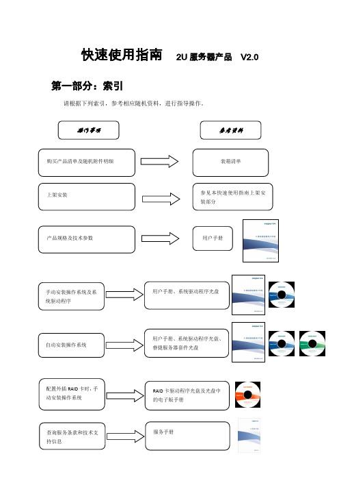
快速使用指南2U 服务器产品 V2.0第一部分:索引请根据下列索引,参考相应随机资料,进行指导操作。
第二部分:本产品支持的操作系统及说明请参阅随机资料,进行操作系统安装。
随机资料中,仅以当前主流操作系统为例,介绍详细的安装过程。
其他操作系统安装请自行查找相关指导说明或咨询浪潮集团有限公司客户服务中心。
本产品支持操作系统如下(根据所选的配置不同,所支持的操作系统种类不同):Windows Server 2003(SP2)Redhat 5系列(/u1/u2/u3)SUSE EL 10(/SP1/SP2/SP3)Windows Server 2008第三部分:上架安装1、本指南将帮助您了解如何在浪潮服务器机柜或兼容标准工业机柜中安装浪潮2U服务器。
2、按照本指南将服务器安装到机柜后,请参考其他随机资料以获取更多的使用指导。
3、在加电使用服务器之前,请您先将服务器机箱上的塑料防护膜揭掉。
4、本指南中的图片仅供参考,请以实物为准。
一、机柜准备角轨调节:为了保证2U服务器能够正常安装到机柜中,机柜角轨的前后间距至少要调整到大于740mm。
调平机柜:机柜必须安放在一个稳固的地方,调节机柜底部的四个调节支脚,使机柜平稳的安放于地面。
同时拆下机柜门以方便导轨安装。
机柜接地:为了避免电击危险,必须在机柜内安装一个接地装置。
如果服务器电源线插入了作为机柜的一部分的电源插座里,必须为机柜提供适当的接地。
如果服务器的电源线插入了在墙上的电源插座里,电源插座里的接地装置仅仅为服务器提供了接地,必须为机柜及其内部的其他设备提供适当的接地保护。
我们推荐您使用浪潮专门为该款服务器所设计的机柜。
如果您使用的是浪潮专门为该机型所配置的机柜的话,机柜内部都已经安全的接地了。
请您尽量不要更改机柜内各接地连接。
温度:如果服务器安装在机柜内,服务器的操作、工作温度,不能低于5℃,不能高于35℃。
通风:服务器集群用的机柜必须为服务器的前部提供足够的风流来散热,并且必须保证能够每小时排放4100Btu的热量。
服务器安装与维护 PPT课件

▪ 图为RAID 0完成截图 仅供参考
14
Windows Server 2003系统安装
▪ 1、启动计算机,按“Delete”键进入计算 机主板BIOS界面,进行启动设置。
15
▪ 2、按“F10”键保存并退出BIOS设置。
16
▪ 3、重新启动计算机,进入Windows Server 2003安装界面,开始运行Windows Server 2003安装程序。
41
▪ 24、继续复制文件。
42
▪ 25、安装开始菜单项 。
43
▪ 26、注册组件。
44
▪ 27、删除安装系统过程中的临时文件。
45
▪ 28、重新启动计算机,显示Windows Server 2003登录界面,安装完成。
46
服务器维护
▪ 安装配置好服务器软件系统,经测试能够 正常使用后,用GHOST软件备份好服务器 系统。备份文件本机一份,光盘或移动存 储一份。
读旧的数据及奇偶信息,两次写新的数据
及奇偶信息。
7
组建RAID 1磁盘阵列
▪ 为保证硬盘数据安全,在安装操作系统前,将硬 盘组成RAID 1磁盘阵列
▪ 进入BIOS,在advanced选项里,把ATA/IDE设 置为enhanced
8
组建RAID 1磁盘阵列
▪ 接着把下面的“Intel Raid Technology”选项, 把其设为“Enabled”,就可以在BIOS中打开 RAID功能了
HKEY_LOCAL_MACHINESYSTEMCurrentControl SetServices项进行查找,通过查看各服务的名称、 对应的执行文件来确定是否是后门、木马程序等。
50
▪ 6.查看相关日志 ▪ 运行eventvwr.msc,粗略检查系统中的相
2023年OTII 2U服务器技术规范

目录版权声明 (I)编制说明 ................................................................. I I 前言 . (I11)一、Mii (1)二、术语、缩略语 (1)三、总体要求 (2)四、配置要求 (2)(一)单路服务器规格 (2)(二)双路服务器规格 (4)五、设计要求 (5)(一)机框 (5)1. 规格尺寸 (5)2. 前面板布局 (6)3. 后面板布局 (7)4. 按钮和指示灯 (8)5. 上架安装 (9)(二)部件 (9)1. 逻辑框图 (9)2. CPU (10)3. ...................................................H6. 加速硬件 (12)7. 时钟和同步(可选) (13)8. IO模块(可选) (14)(三)电源 (15)1. ∙'J (15)2. 转换效率 (15)3. 冗余和热插拔 (15)4∙全和保护.・・・・・・・・・・・・・・・・・・・・・・・・・・・・・・・・・・・・・・・・・・・・155. 电源管理 (15)(四)风扇 (16)1. 规格尺寸 (16)2. 冗余和热插拔 (16)3. 风扇调速 (16)六、环境要求 (16)七、劄里要求 (17)(一)带外管理功能 (17)1. 资产管理 (17)2. 部件信息管理 (17)3. 传感器监控 (18)4. 电源和风扇管理 (18)5. 故障告警 (19)7.其他功能 (20)(二)带内管理功能 (20)八、软件兼容性 (21)OTII(OpenTeIecomITInfraStr11Ct11re)即电信开放IT基础设施项目,隶属于中国最大的开源硬件组织一开放数据中心委员会(ODCC)。
2023年11月由中国移动联合中国电信、中国联通、中国信通院、英特尔等公司共同发起,是业界首个由多家运营商联合发起的服务器开发合作项目,首要目标是形成面向5G及边缘计算的深度定制、开放标准、统一规范的服务器技术方案及产品。
DELL双路服务器安装全过程
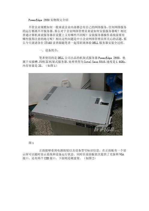
PowerEdge 2950提供了三个硬盘协同工作,我们可以从前面板将这三个硬盘取出随意更换,不过由于日后三块硬盘要协同建立RAID5数据保护系统,所以一旦系统建立就不要随意更换了,否则重新建立所需时间会比较长。(如图7)
图7
PowerEdge 2950使用的硬盘是SAS接口的由seagate公司出品的,硬盘是3.5英寸热插拔硬盘,转速达到15000转,容量是146G。(如图8)
图2
在实际使用过程中我们点正面“i”按钮可以让显示屏在不同状态下进行切换,从而显示不同信息。(如图3)
图3
PowerEdge 2950后面板提供的接口更多,从左向右依次是VGA接口,USB接口和两个千M以太网卡接口,同时在右边提供了双电源接口,保证设备具备双路供电系统让PowerEdge 2950可以更稳定的运行,电源的冗余也是服务器有别于普通计算机的一大特点。(如图4)
图33
完成全部设置后我们将可以顺利的进入到选择的操作系统中,设置服务和网络应用为企业内网服务。当然DELL提供的安装光盘中还提供了很多诊断工具,在日后使用过程中如果出现问题我们都可以通过这些工具快速查找故障根源,从而在第一时间解决问题。
四、总结:
至此我们就完成了DELL服务器PowerEdge 2950的全部安装和初始化工作,总体来说服务器相比普通台式机在安装过程和初始化步骤上有所区别,针对磁盘的设置会比较多,例如RAID系统建立等。当然如果拥有厂商提供的安装向导的话我们就可以更加高效的完成上述工作,因此笔者也建议各位网络管理员尽可能的通过厂商安装向导光盘来完成安装工作,这样也可以避免故障和不明问题的发生。
图4
除了常规接口外在下排接口上方提供了扩展插槽,我们可以从图中看到写有PCI 2,PCI 3的字样,在日后运行过程中我们可以通过这些插槽针对PowerEdge 2950服务器进行升级。(如图5)
2U服务器安装图解
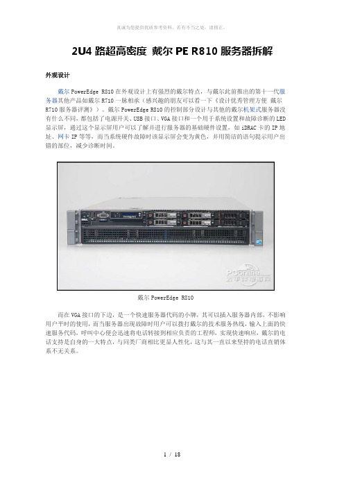
2U4路超高密度戴尔PE R810服务器拆解外观设计戴尔PowerEdge R810在外观设计上有强烈的戴尔特点,与戴尔此前推出的第十一代服务器其他产品如戴尔R710一脉相承(感兴趣的朋友可以看一下《设计优秀管理方便戴尔R710服务器评测》)。
戴尔PowerEdge R810的控制部分设计与其他的戴尔机架式服务器没有什么不同,都包括了电源开关、USB接口、VGA接口和一个用于系统设置和故障诊断的LED 显示屏,通过这个显示屏用户可以了解并进行服务器的基础硬件设置,如iDRAC卡的IP地址、网卡IP等等,而当系统硬件故障时该显示屏会变为黄色,并用简洁的语句提示用户出错的部位,减少诊断时间。
戴尔PowerEdge R810而在VGA接口的下边,是一个快速服务器代码的小牌,其可以插入服务器内部,不影响用户平时的使用,而当服务器出现故障时用户可以拨打戴尔的技术服务热线,输入上面的快速服务代码,呼叫中心便会迅速将电话转接到相应负责的工程师,实现快速响应,戴尔的电话支持是自身的一大特点,与同类厂商相比更显人性化,这与其一直以来坚持的电话直销体系不无关系。
戴尔PowerEdge R810的控制面板在LED显示屏的下面是一个光驱位,在本次送测的产品中没有配备光驱,但用户在购买时可以选购,光驱的安装也相当方便,无需借助螺丝刀等工具,服务器设计有托架,用户直接插入即可,非常简单。
戴尔PowerEdge R810配备的硬盘由于内部设计的原因,戴尔PowerEdge R810的前面板设计分成了上下两个部分,下面的部分完全是散热孔。
而在上面的部分除了控制台之外还提供了存储位置。
这款服务器提供了6个2.5英寸的硬盘位,本次送测的机器配备了4个转速15K的6Gb SAS硬盘,单盘容量147G。
戴尔PowerEdge R810后面板接下来我们再来看一下其后面板的设计,戴尔PowerEdge R810的后面板提供了不少的I/O接口,包括四个板载的千兆网络端口,两个USB接口、VGA接口、串口等,而除此之外,这款产品还提供了iDRAC Enterprise卡,除了一个百兆的管理网络端口之外还提供了一个SD卡插槽,可以放置操作系统宕机之后的紧急状态启动的备用系统,应对突发状况,而另外一个就是这款送测的产品提供了一个万兆的网卡,对于高性能网络来说非常必要。
2U服务器安装图解解读
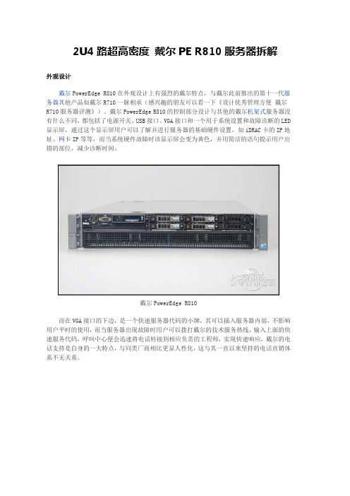
2U4路超高密度戴尔PE R810服务器拆解外观设计戴尔PowerEdge R810在外观设计上有强烈的戴尔特点,与戴尔此前推出的第十一代服务器其他产品如戴尔R710一脉相承(感兴趣的朋友可以看一下《设计优秀管理方便戴尔R710服务器评测》)。
戴尔PowerEdge R810的控制部分设计与其他的戴尔机架式服务器没有什么不同,都包括了电源开关、USB接口、VGA接口和一个用于系统设置和故障诊断的LED 显示屏,通过这个显示屏用户可以了解并进行服务器的基础硬件设置,如iDRAC卡的IP地址、网卡IP等等,而当系统硬件故障时该显示屏会变为黄色,并用简洁的语句提示用户出错的部位,减少诊断时间。
戴尔PowerEdge R810而在VGA接口的下边,是一个快速服务器代码的小牌,其可以插入服务器内部,不影响用户平时的使用,而当服务器出现故障时用户可以拨打戴尔的技术服务热线,输入上面的快速服务代码,呼叫中心便会迅速将电话转接到相应负责的工程师,实现快速响应,戴尔的电话支持是自身的一大特点,与同类厂商相比更显人性化,这与其一直以来坚持的电话直销体系不无关系。
戴尔PowerEdge R810的控制面板在LED显示屏的下面是一个光驱位,在本次送测的产品中没有配备光驱,但用户在购买时可以选购,光驱的安装也相当方便,无需借助螺丝刀等工具,服务器设计有托架,用户直接插入即可,非常简单。
戴尔PowerEdge R810配备的硬盘由于内部设计的原因,戴尔PowerEdge R810的前面板设计分成了上下两个部分,下面的部分完全是散热孔。
而在上面的部分除了控制台之外还提供了存储位置。
这款服务器提供了6个2.5英寸的硬盘位,本次送测的机器配备了4个转速15K的6Gb SAS硬盘,单盘容量147G。
戴尔PowerEdge R810后面板接下来我们再来看一下其后面板的设计,戴尔PowerEdge R810的后面板提供了不少的I/O接口,包括四个板载的千兆网络端口,两个USB接口、VGA接口、串口等,而除此之外,这款产品还提供了iDRAC Enterprise卡,除了一个百兆的管理网络端口之外还提供了一个SD卡插槽,可以放置操作系统宕机之后的紧急状态启动的备用系统,应对突发状况,而另外一个就是这款送测的产品提供了一个万兆的网卡,对于高性能网络来说非常必要。
服务器面板2U

服务器面板2U服务器面板是服务器机箱上的一个组件,用于控制和管理服务器的各项功能和设置。
2U服务器面板则指的是一种适用于2U机箱的面板设计。
本文将会对2U服务器面板的功能、优势以及使用场景进行详细介绍。
一、功能和特点1. 远程管理:2U服务器面板可以通过网络远程管理服务器,无需物理接触服务器,方便管理员进行远程配置、监控和故障排除。
2. 电源管理:通过2U服务器面板,管理员可以对服务器的电源进行管理,包括开关机、重启、电源状态监控等功能。
3. 硬件监控:2U服务器面板可以监控服务器的硬件状态,如CPU温度、风扇转速、电源功耗等,并及时提供报警和通知功能,保证服务器的正常运行。
4. 远程控制:除了远程管理和监控功能外,2U服务器面板还支持远程控制服务器的操作系统,包括远程登录、文件传输、虚拟光驱等功能,方便管理员对服务器进行维护和操作。
5. 安全性:2U服务器面板提供了安全认证和权限控制功能,只有经过授权的管理员才能够访问和管理服务器,保障了服务器的安全性。
二、优势1. 空间占用小:2U服务器面板的设计考虑了机箱的尺寸限制,因此在保持丰富功能的同时,尽量减小了空间占用,为服务器的硬件组件留下更多空间,提高了服务器的整体性能。
2. 省电节能:2U服务器面板具备电源管理功能,可以对服务器的电源进行有效控制,避免不必要的能源浪费,达到省电节能的目的,降低服务器运行成本。
3. 管理便捷:2U服务器面板提供了统一的管理界面,管理员可以通过一个面板对多台服务器进行管理,简化了管理流程,提高了工作效率。
4. 故障排除迅速:通过2U服务器面板提供的远程管理和监控功能,管理员可以及时发现服务器的故障和异常,以便快速进行排除和修复,提高了服务器的可靠性和可用性。
三、使用场景1. 数据中心:对于大型的数据中心来说,2U服务器面板是管理和维护服务器的重要工具,可以提高管理员的工作效率,减少维护成本,并确保数据中心的稳定运行。
ThinkSystem DE 系列 2U 和 4U 机柜 硬件安装与维护指南说明书

DE 系列硬件概述 . . . . . . . . . . . . . . 1 前视图 . . . . . . . . . . . . . . . . . 2 后视图 . . . . . . . . . . . . . . . . . 3 DE2000 系列的规格. . . . . . . . . . . . 9 DE4000 系列的规格. . . . . . . . . . . 13 DE6000 系列的规格. . . . . . . . . . . 19 驱动器存储架的规格 . . . . . . . . . . 24
第二版 (2019 年 12 月) © Copyright Lenovo 2019. 有限权利声明:如果数据或软件依照美国总务署(GSA)合同提供,则其使用、复制或公开受编号为 GS-35F-05925 的 合同条款的约束。
目录
安全 . . . . . . . . . . . . . . . . . . iii
Læs sikkerhedsforskrifterne, før du installerer dette produkt. Lees voordat u dit product installeert eerst de veiligheidsvoorschriften. Ennen kuin asennat tämän tuotteen, lue turvaohjeet kohdasta Safety Information. Avant d'installer ce produit, lisez les consignes de sécurité. Vor der Installation dieses Produkts die Sicherheitshinweise lesen.
如何组装2U服务器
如何组装2U存储服务器?大家好!今天的主题是如何组装2U存储服务器,其实说到存储,目前最热点的应用在云平台,大多中小企业对数据的存储都有一定的要求。
今天跟大家谈谈如何搭建2U 8盘位存储服务器,解决为中小企业在硬件方面硬件投入的问题.很多中小型企业的员工时常存储的文件内型较多,还有管理层对员工所访问的文件权限有所限制,种种特殊的要求是每个企业所提出的疑难困惑,究竟什么样的配置才能满足这些企业的要求呢?首先得从硬件着手,为什么呢?硬件的配置是对企业的访问量大小有直接影响。
所以按照一个中小企业50名员工的日常办公需求,我们建议采用以下硬件配置足以满足企业的存储需求。
为什么说采用机架式服务器呢?西安唯本电子信息技术有限公司薛工程师告诉我,通常企业都配有信息中心机房,服务器一般都放在信息中心里,机架式服务器是放入服务器机柜中,以便节约放置空间,而且服务器一般都不外接显示器,独立放置比较好一些,还有从安全角度上说也比较好,避免公司其他员工私自打开服务器操作。
2U机架式服务器一般提供8-12个硬盘盘位,这样就可以解决企业在服务器上对硬盘容量的要求,硬盘容量的扩展性比较高。
西安唯本电子信息技术有限公司杨经理告诉我们,他们公司定制研发的2U服务器机箱唯本2U R23608P表面上看是有8个热插拔盘位,其实是10个盘位,他们的机架式服务器机箱内置2个2.5寸SSD盘位,这样更好的解决了企业在硬盘盘位上的纠结了,因为机架式服务器的价格跟硬盘位的数量有一定的关系,薛工程师说他们公司的机箱内置的硬盘盘位刚好为企业服务器安装各种操作系统,现在多数定制组装服务器都采用读取速度非常快的固态硬盘做操作系统盘,这样买8盘位机架式服务器就可以最大支持24TB容量了,普通服务器机箱就不能做到这一点。
服务器机箱一定要带热插拔功能,方便省事。
再次说CPU,大家都知道,在大多数员工同时访问服务器的时候,CPU就起一个关键的处理作用。
双路至强Xeon四核系列,这样的配置对于50多个数据访问量来说有足够的支持能力,依据我的经验。
服务器的安装和调试详细图解

服务器的安装和调试详细图解1.安装DNS服务组件默认情况下Windows Server 2003(SP1)没有安装DNS服务组件,用户需要手动添加,操作步骤如下所述:第1步,在“控制面板”中打开“添加或删除程序”窗口,并单击“添加/删除Windows组件”按钮,打开“Windows组件安装向导”对话框。
第2步,在“Windows组件”对话框中双击【网络服务】选项,打开【网络服务】对话框。
在【网络服务的子组件】列表中选中【域名系统(DNS)】复选框,并单击【确定】按钮。
按照系统提示安装DNS组件。
在安装过程中需要提供Windows Server 2003系统安装光盘或指定安装文件路径,如图1所示。
图1选中【域名系统(DNS)】复选框提示:要想使在局域网中搭建的DNS服务器能够解析来自Internet的域名解析请求,必须向域名申请机构(如新网,或万网)申请正式的域名,并注册DNS解析服务。
另外局域网中的DNS服务器还必须拥有能够被Internet访问的固定IP地址。
2.创建正向查找区域DNS服务器安装完成以后会自动打开“配置DNS服务器向导”对话框。
在该向导的指引下开始创建第一个区域,操作步骤如下所述:第1步,在开始菜单中依次单击【管理工具】→【DNS】菜单项,打开dnsmgmt窗口。
在左窗格中右键单击服务器名称,选择【配置DNS服务器】命令,如图2所示图2选择【配置DNS服务器】命令第2步,打开“配置DNS服务器向导”对话框,在欢迎对话框中单击【下一步】按钮。
打开“选择配置操作”对话框,在默认情况下适合小型网络使用的【创建正向查找区域】单选钮处于选中状态。
保持默认设置并单击【下一步】按钮,如图3所示。
图3“选择配置操作”对话框提示:上述步骤创建的正向查找区域是指将域名解析为IP地址的过程。
即当用户输入某个域名时,借助于该记录可以将域名解析为IP地址,从而实现对服务器的访问。
第3步,打开“主服务器位置”对话框,选中【这台服务器维护该区域】单选钮,并单击【下一步】按钮,如图4所示。
2U服务器安装硬件安装说明文档

2U存储服务器硬件安装说明文档系统集成实验室1.步骤概要2.详细图文步骤1、首先,将2U机箱后盖按照指示方向打开2、打开后盖,安装机箱后面的I/O插槽,插槽是从内部卡进去的3、在机箱底板上安装用于固定主板用的9个螺帽(具体位置根据主板的螺帽孔位来定)对于此机箱,共有九个螺帽孔。
在此还要注意的是,主板的螺帽孔和机箱的孔一定要对应,不能多不能少,不然会导致主板烧毁!4、给主板上CPU和CPU风扇(在此要注意上CPU的位置摆放和风扇的风口朝向)安装CPU风扇的时候,在风扇底部涂上硅胶,并要注意风扇的朝向,同时,在上螺丝的时候要注意松紧程度,不然会压坏CPU。
5、安装内存卡条,内存条的大小是根据CPU的型号而定,且内存条是安装在蓝色的卡槽内。
6、将主板放入机箱,并注意与9个螺帽对齐再次强调,主板和螺帽必须一一对应,否则在加电的时候因短路而会烧坏主板。
给主板上螺丝钉7、安装供电线缆线缆最后需要固定,要注意不要让线缆触碰到风扇,以免引起故障8、USB前置数据线有USB线和GND线两部分组成(注意排线顺序不能弄错,否则会导致USB端设备损坏)9、安装USB前置数据线要注意的是如图所示,前置线要紧靠边框,带字的一面要面向机箱散热孔边框,GND线是图示中左边的那根黑线,最右边的红色线是USB V+ 线10、安装USB前置数据线完毕后要注意固定好线缆11、安装插线 POWER-LED(此线要切开)、HDD-LED、POWER-SW、RESET-SW、NIC1、NIC2对应的实物图如下12、硬盘数据线安装位置(因为只用到两张盘,所以只接图示位置即可)在下图线上,已经标注了连线的顺序。
2U服务器安装图解
2U服务器安装图解1. 介绍在本文档中,我们将详细说明如何正确地安装一台2U服务器。
通过图解和文字描述,您可以轻松了解每个步骤的具体操作方法。
2. 准备工作在开始之前,请确保已经准备好以下物品:- 一个适用于该型号服务器的机架或支架。
- 所需数量的螺丝和其他固定件。
- 相应规格及容量的硬盘、内存等组件(根据实际需要)。
3. 安装过程步骤1:打开机箱门并检查内容物是否完整。
确认所有配件都在包裹里,并按照清单核对数量。
步骤2:选择合适位置放置你要安装这台服务器设备,在此基础上确定所选区域有足够空间供给后期使用以及散发出来产生高温时候能得到良好排风效果.步骤3: 小心提起主板, 并插入CPU芯片至相应槽位上.图例:[图片]4. 连接电源线确认连接方式无误后即可通电启动测试运行情况5.配置BIOS设置按下DEL键进入bios界面,进行相应的设置6. 安装操作系统根据实际需求选择合适的操作系统,并按照安装向导完成相关步骤。
7.连接网络将服务器与局域网或互联网连接起来。
8. 配置防火墙和安全性设置为了保护您的数据和服务器免受潜在威胁,请配置防火墙并采取其他必要措施提高服务器的安全性。
9.备份策略制定一个有效且可靠地备份计划以确保重要数据不会丢失。
10.维护与升级定期检查硬件设备是否正常工作,并根据需要对其进行升级或更换部分组件。
11. 结束语感谢您使用本文档所提供的2U服务器安装图解指南。
如果有任何问题,请随时联系我们获取进一步帮助。
12、本文档涉及附件:- 图片文件:包含示意图等图片素材13、法律名词及注释:- CPU芯片: 中央处理器(Central Processing Unit)是电子计算机中心思考运行核心, 是整个主板上最关键也是负责所有数学/逻辑运算任务.- BIOS: 基本输入输出系统(Basic Input/Output System)是一种固化在计算机主板上的固件,它包含了开机自检、硬件初始化以及启动操作系统等功能。
戴尔 PowerEdge R815 四路2U机架式服务器 产品说明书

性能优化技术Dell PowerEdge R815是为实现高价值、高性能目标而全新设计的一款服务器,不但提供可靠的基础,而且平衡搭配最新AMD 皓龙处理器技术,以求实现稳定性、一致性和超高性价比。
对于期望最大限度地利用数据中心空间和预算的客户而言,这是一个理想的平台。
为可靠性而构建我们根据客户意见,构建了可靠性高、可用性强且质量一流的服务器。
戴尔对可靠性的承诺很简单:提供能经受住时间考验的高品质产品。
从坚固的金属硬盘托架与排列有序的布线,到交互式液晶显示屏、双SD 虚拟机管理程序模块和嵌入式诊断程序,所有组件在设计和构建时都以提高服务器可靠性和可用性为宗旨。
戴尔在提升其可靠性流程方面采取了以下措施:• 采用完善的验证和测试流程,使产品设计更加耐用 • 确认每个供应商是否满足严格的质量标准• 实施“单人负责制”(one-touch)构建流程,确保由一个人全权监督服务器的整个构建过程,执行更严格的质量控制• 确保每台配置完整的戴尔服务器在出厂之前都经过反复测试• 引进统一服务器配置器(USC),它无需介质便可提供持久的嵌入式诊断,有助于最大限度地缩短停机时间• 采用坚固耐用的工业材料,以延长产品的生命周期• 通过添加双内置故障安全SD 模块(可在虚拟机管理程序级别提供故障转移功能)等特性来逐代提高冗余性除了以上这些质量措施之外,所有第11代服务器的外接端口、电源与LED 指示灯或液晶显示屏都布置在相同的位置,不但能使用户获得更加熟悉而高效的使用体验,同时也方便他们执行安装和部署。
高效的基础架构空间、电力以及散热能力的限制,加之能源成本的不断提高,使IT 部门面临严峻挑战。
戴尔最新的Dell PowerEdge 服务器将能效作为一项设计标准,同时还能实现您的基础架构所要求的性能及预算目标。
高能效的系统设计采用了多项智能节能技术,包括针对您特定环境的功率封顶、功率清点和功率预算的电源管理功能。
PowerEdge R815机箱配备高效风扇,可根据服务器工作负载的需求调整转速。
S2206 (2U24) MS-S312服务器系统用户指南说明书
S2206 (2U24) MS-S312 Server SystemUser Guide2ContentsRevision V1.0, 2023/04Contents Regulatory Notices .......................................................................................................4Copyright and Trademarks Notice ..............................................................................5Technical Support.........................................................................................................5Safety Information ........................................................................................................6System Specifications ..................................................................................................7System Overview . (8)S2206-03 .................................................................................................................8S2206-04 .................................................................................................................8System LED Indicators ...............................................................................................11Motherboard Overview ...............................................................................................12Motherboard Connector ............................................................................................13Power Connector ..................................................................................................13Storage Connector ................................................................................................15FPC Connector ......................................................................................................17Box Header ...........................................................................................................19Motherboard Jumper .................................................................................................24Motherboard Expansion Slot .....................................................................................25Getting Started ............................................................................................................26Necessary Tools ...................................................................................................26Safety Precautions ................................................................................................26System Setup ..............................................................................................................27Drive Bay (27)Installing 2.5" HDD/ SSD ......................................................................................27System Cover ..............................................................................................................28Removing System Cover (28)CPU & Heatsink (29)Installing CPU & Heatsink (30)Memory (33)Recommended Memory Population (34)Installing Memory Modules (35)M.2 M Key (36)Installing M.2 M Key (36)PCIe Add-in Card (37)Installing PCIe Add-in Card (37)Installing Riser Card Assembly (38)System Fan (39)Installing 2U Fan (39)Installing 2U Fan Cage (40)Air Duct (41)Installing Air Duct (41)Power Supply Unit (PSU) (42)Installing PSU (42)3ContentsRegulatory NoticesWEEE StatementUnder the European Union (“EU”) Directive on Waste Electrical and Electronic Equipment, Directive 2012/19/EU, products of “electrical and electronic equipment” cannot be discarded as municipal waste anymore and manufacturers of covered electronic equipment will be obligated to take back such products at the end of their useful life. Chemical Substances InformationIn compliance with chemical substances regulations, such as the EU REACH Regulation (Regulation EC No. 1907/2006 of the European Parliament and the Council), MSI provides the information of chemical substances in products at: https:///global/indexCE ConformityHereby, Micro-Star International CO., LTD declares that this device is in compliance with the essential safety requirements and other relevant provisions set out in the European Directive.FCC-A Radio Frequency Interference StatementThis equipment has been tested and found to comply with the limitsfor a Class A digital device, pursuant to Part 15 of the FCC Rules. These limits are designed to provide reasonable protection against harmful interference when the equipment is operated in a commercial environment. This equipment generates, uses and can radiate radio frequency energy and, if not installed and used in accordance with the instruction manual, may cause harmful interference to radio communications. Operation of this equipment in a residential area is likely to cause harmful interference, in which case the user will be required to correct the interference at his own expense. Notice 1The changes or modifications not expressly approved by the party responsible for compliance could void the user’s authority to operate the equipment. Notice 2Shielded interface cables and AC power cord, if any, must be used in order to comply with the emission limits.This device complies with Part 15 of the FCC Rules. Operation is subject to the following two conditions:∙This device may not cause harmful interference, and∙This device must accept any interference received, including interference that may cause undesired operation.4Regulatory NoticesBattery InformationPlease take special precautions if this product comes with a battery.∙Danger of explosion if battery is incorrectly replaced. Replace only with the same or equivalent type recommended by the manufacturer.∙Avoid disposal of a battery into fire or a hot oven, or mechanically crushing or cutting of a battery, which can result in an explosion.∙Avoid leaving a battery in an extremely high temperature or extremely low air pressure environment that can result in an explosion or the leakage of flammable liquid or gas.∙Do not ingest battery. If the coin/button cell battery is swallowed, it can cause severe internal burns and can lead to death. Keep new and used batteries away from children.European Union:Batteries, battery packs, and accumulators should not be disposed of asunsorted household waste. Please use the public collection system toreturn, recycle, or treat them in compliance with the local regulations. BSMI:廢電池請回收For better environmental protection, waste batteries should be collectedseparately for recycling or special disposal.California, USA:The button cell battery may contain perchlorate material and requiresspecial handling when recycled or disposed of in California.For further information please visit:/hazardouswaste/perchlorate/ Copyright and Trademarks NoticeCopyright © Micro-Star Int’l Co., Ltd. All rights reserved. The MSI logo used isa registered trademark of Micro-Star Int’l Co., Ltd. All other marks and names mentioned may be trademarks of their respective owners. No warranty as to accuracy or completeness is expressed or implied. MSI reserves the right to make changes to this document without prior notice. Technical SupportIf a problem arises with your product and no solution can be obtained from the user’s manual, please contact your place of purchase or local distributor. Alternatively, please visit https:///support/ for further guidance.5Copyright and Trademarks NoticeSafety Information∙Always read the safety instructions carefully.∙Keep this User’s Manual for future reference.∙Keep this equipment away from humidity.∙Lay this equipment on a reliable flat surface before setting it up.∙The openings on the enclosure are for air convection hence protects the equipment from overheating. Do not cover the openings.∙Make sure the voltage of the power source and adjust properly before connecting the equipment to the power inlet.∙Place the power cord such a way that people can not step on it. Do not place anything over the power cord.∙Always unplug the power cord before inserting any add-on card or module.∙All cautions and warnings on the equipment should be noted.∙Never pour any liquid into the opening that could damage or cause electrical shock.∙If any of the following situations arises, get the equipment checked by service personnel:∙The power cord or plug is damaged.∙Liquid has penetrated into the equipment.∙The equipment has been exposed to moisture.∙The equipment does not work well or you can not get it work according to User’sManual.∙The equipment has dropped and damaged.∙The equipment has obvious sign of breakage.∙Do not leave this equipment in an environment unconditioned, storage temperature above 60°C (140°F), it may damage the equipment.6Safety Information7 System SpecificationsSystem OverviewS2206-0324 x 2.5” NVMeHot-Swap Drive BaysS2206-0416 x 2.5” NVMeHot-Swap Drive Bays8 x 2.5” SATAHot-Swap Drive Bays8System Overview9System Overview10System Overview11System LED IndicatorsSystem LED IndicatorsSystem Power Button/ LEDSystem Reset Button UID Button/ LED ! System Status LEDM.2 Activity LEDNIC Link LED12Motherboard Overview13Motherboard ConnectorPSU_PWR1~2: CRPS Power ConnectorThese CRPS (Common Redundant Power Supplies) connectors allow you to connect a power supply. To connect the power supply, ensure that the plug is inserted in the proper orientation and that the pins are aligned. Then firmly push down the power supply into the connector.GPU_PWR1~6: GPU Power ConnectorThese connectors provide power output to GPUs.HDD_PWR1~2: HDD BP Power ConnectorGPU_PWR4GPU_PWR5HDD_PWR2HDD_PWR1HDD_PWR3: Rear HDD BP Power ConnectorMake sure that all power connectors are securely connected to the power supply to ensure stable operation of the motherboard.14Motherboard Connector15Motherboard ConnectorJMCIO1~4: MCIO 4i ConnectorThese are right-angle 38-pin Mini Cool Edge IO (MCIO) connectors, which support PCIe 4.0 x4 16GT/s and SATA 3.0 6Gb/s interfaces. A JSATA_NVME_SW1 jumper can be used to switch signals between SATA and PCIe NVMe (Default).JMCIO5, JMCIO6: MCIO 8i ConnectorThese are vertical 74-pin Mini Cool Edge IO (MCIO) connectors, which support PCIe 4.0 x8 16GT/s interface .JSLIM4X_1: Slimline SAS 4i ConnectorThis is 38-pin Slimline SAS 4i connector, which support PCIe 3.0 x4 8GT/s interface .M2_2M2_1MSD1MSD2JMCIO1JMCIO2JMCIO3JSLIM4X_1JMCIO4JMCIO6JMCIO5M2_1, M2_2: M.2 Slot (M Key, PCIe 3.0 x2, 2280)The M.2 slot supports solid-state drive (SSD). For Installation procedure, please refer.to “System Setup > M.2 M Key"MSD1, MSD2: Micro SD Card Slot16Motherboard ConnectorFPC ConnectorA Flexible Printed Circuit (FPC) connector connects a flexible printed circuit or flat ribbon cable to a PCB. FPC connectors are also referred to as flat flexible cable (FFC) connectors or ribbon connectors. Their slim and lightweight design makes them ideal for electronic devices and equipment that require space-saving solutions.JFP1: Front Panel FPC ConnectorThe front panel connector is provided for electrical connection to the front panel17Motherboard ConnectorJUSB2: USB FPC ConnectorThis port is backward-compatible with USB 2.0 devices and supports data transfer18Motherboard ConnectorBox HeaderF2U-1~6: 2U System Fan Power Connector19Motherboard Connector20Motherboard ConnectorJCHASSIS1: Chassis Intrusion HeaderThis connector connects to the chassis intrusion switch cable. If the chassis is opened, the chassis intrusion mechanism will be activated. The system will record this status and show a warning message on the screen. To clear the warning, you must enter theBIOS utility and clear the record.Normal(default)JCHASSIS1Trigger the chassis intrusioneventJUSB1: USB 3.2 Gen 1 Type-A Connector The USB (Universal Serial Bus) port is for attaching USB devices such as keyboard, mouse, or other USB-compatible devices. It supports up to 5 Gbit/s (SuperSpeed) data transfer rate.JIPMB1: IPMB Box HeaderJTPM1: SPI TPM Module Box HeaderThis connector connects to a TPM (Trusted Platform Module) module (optional).JTPM121Motherboard ConnectorJFP_VGA1: Front VGA Header22Motherboard ConnectorFBP_I2C_1, RBP_I2C_1, RBP_I2C_2: I2C Box HeaderI2C connectors are used to connect to the System Management Bus (SMBus). FBP_I2C_1 is for front HDD backplane, and RBP_I2C_1, RBP_I2C_2 are for rear HDDFBP_I2C_123Motherboard Connector24Motherboard JumperMotherboard Jumper⚠ImportantAvoid adjusting jumpers when the system is on; it will damage the motherboard.JSPI_MUX1JSATA_NVME_SW1PCIe (Peripheral Component Interconnect Express) SlotsThe PCI Express slots support PCIe interface expansion cards.OCP (Open Compute Project) LAN Mezzanine SlotThe slots allows the deployment of a wide variety of additional networking options through OCP Mezzanine Ethernet cards.⚠ImportantWhen adding or removing expansion cards, make sure that you unplug the power supply first. Meanwhile, read the documentation for the expansion card to configure any necessary hardware or software settings for the expansion card, such as jumpers, switches or BIOS configuration.25Motherboard Expansion Slot∙All information is subject to change without prior notice.∙The system photos are provided for demonstration purposes only. The appearance and internal view of your system may vary depending on the model you purchased. Necessary ToolsScrewdriver PliersTweezers Anti-Static GlovesSafety PrecautionsThe following precautions should be observed while handling the system:∙Place the system on a flat and stable surface.∙Do not place the system in environments subject to mist, smoke, vibration,excessive dust, salty or greasy air, or other corrosive gases and fumes.∙Do not drop or jolt the system.∙Do not use a power adapter other than the one enclosed with the system.∙Disconnect the power cord before performing any installation procedures on thesystem.∙Do not perform any maintenance with wet hands.∙Prevent foreign substances, such as water, other liquids or chemicals, fromentering the system while performing installation procedures.∙Use a grounded wrist strap before handling system components such as CPU,Memory, HDD, expansion cards, etc.∙Place system components on a grounded antistatic pad or on the bed that came with the components whenever the components are separated from the system.26Getting StartedBefore removing or installing any components, make sure the system is not turned on or connected to the power.Drive BayInstalling 2.5" HDD/ SSD1. Engage two embossed pins into the side dimples on the HDD/ SSD.2. Carefully push down the other side of the HDD/ SSD until another two embossed pins and side dimples lock it into place.3. With the lever open, insert the 2.5” HDD/ SSD assembly vertically into the drive bay until the locking lever is engaged.4.Push in the lever to lock it into place.27System SetupSystem CoverRemoving System Cover1. Remove the screws securing the system on both sides.2. To remove the top cover panels, press down on the release latches on both sidesand then slide them to the front or back side of the system.28System Cover29CPU & HeatsinkCPU & HeatsinkUse appropriate ground straps, gloves and ESD mats to protect yourself fromelectrostatic discharge (ESD) while installing the processor.⚠Important∙Overheating will seriously damage the CPU and system. Always make sure the cooling fan can work properly to protect the CPU from overheating. Make sure that you apply an even layer of thermal paste (or thermal tape) between the CPU and the heatsink to enhance heat dissipation.∙While replacing the CPU , always turn off the power supply or unplug the power supply’s power cord from the grounded outlet first to ensure the safety of CPU. ∙Do not touch the CPU socket content to avoid damage.∙Whenever CPU is not installed, always protect your CPU socket pins with the plastic cap covered.∙Please refer to the documentation in the CPU cooler package for more details about the CPU cooler installation.∙Read the CPU status in BIOS.30CPU & HeatsinkImages are for illustration purposes only; actual parts may vary.1.2. it gently until it is fully open.3. Lift the rail frame by gripping the lift tabs near the front edge of the rail frame. ∙As both frames are spring-loaded, keep a tight grip on them while lifting to avoid an abrupt swinging motion.4. Pull the external cap upward through the rail guides on the rail frame to remove it.5. Grip the handle of the carrier frame and slide it downward with the flanges and the rail guides aligned.∙CPUs are shipped from the factory with pre-assembled carrier frames.∙Make sure the flanges of the carrier frame are firmly loaded on the rails beforeDo not touch thesocket content! 6. Grip the lift tabs at the front edge of the rail frame with the carrier frame loaded,then gently lower it to engage the carrier’s latching mechanism to the sockethousing.31CPU & Heatsink7. Push the retention frame downward and use a torque screwdriver to tighten theTorque Screwdriver SettingsScrew Head: Torx T20Torque: 12.5-15 kgf·cm**12.5-15 kgf·cm= 122.6~147 N·m= 10.9~13 lbf·in8. thermal paste to thebottom center of the heatsink. (Skip this step if there is pre-applied thermal paste.)9. Lower the heatsink until it rests firmly in place after aligning the six screw holeson its bottom with the motherboard’s studs.10. T ighten all screws in diagonal sequence with a torque screwdriver.∙To avoid damaging the fins of the heatsink, always grip the heatsink along the axis of the fins. Holding a heatsink along the side might damage its fins or solder.∙Confirm if your heatsink is firmly installed before turning on your system.#1#232CPU & Heatsink33MemoryMemoryCPU0_DIMM_G1CPU0_DIMM_H1CPU0_DIMM_I1CPU0_DIMM_J1CPU0_DIMM_K1CPU0_DIMM_L1CPU0_DIMM_F1CPU0_DIMM_E1CPU0_DIMM_D1CPU0_DIMM_C1CPU0_DIMM_B1CPU0_DIMM_A1CPU1_DIMM_G1CPU1_DIMM_H1CPU1_DIMM_I1CPU1_DIMM_J1CPU1_DIMM_K1CPU1_DIMM_L1CPU1_DIMM_F1CPU1_DIMM_E1CPU1_DIMM_D1CPU1_DIMM_C1CPU1_DIMM_B1CPU1_DIMM_A1CPU1CPU034MemoryRecommended Memory PopulationCPU1CPU0ImportantThere should be at least one DDR5 DIMM populated.35MemoryInstalling Memory Modules1. Open the side clips to unlock the DIMM slot.2. Insert the DIMM vertically into the slot, ensuring that the off-center notch at the bottom aligns with the slot.3. Push the DIMM firmly into the slot until it clicks and the side clips automatically close.4.Verify that the side clips have securely locked the DIMM in place.⚠ImportantYou can barely see the golden finger if the memory module is properly inserted in the DIMM slot.36M.2 M KeyM.2 M KeyInstalling M.2 M Key⚽ Video DemonstrationWatch the video to learn how toInstall M.2 SSD.2. Secure the M.2 SSD inplace with the supplied M.2 screw.1. Insert your M.2 SSDinto the M.2 slot at a 30-degree angle.PCIe Add-in CardInstalling PCIe Add-in Card1. Loosen the screws on the riser bracket to remove the filler panels.2. Align the PCIe add-in card with the connector on the riser card, and insert it until it is fully seated.3. Tighten the screws to securely fix the PCIe add-in card in place.⚠ImportantThe procedure for installing PCIe add-in cards are the same for all the riser slots.337PCIe Add-in CardInstalling Riser Card Assembly1. Make sure the key slots on the rear edge of the riser card assembly are aligned withthe mounting pins on the rear edge of the system (indicated by the red circle in the image below).2. Insert the riser card assembly into the PCIe slot on the system board.3. Tighten the screws on the rear side of the system to secure the riser card assembly.38PCIe Add-in CardSystem FanThe server system is equipped with six 60 x 60 x 38mm hot-swappable system fans that provide primary airflow to maintain optimal cooling and prevent overheating. The fan features include:∙Tachometer on each fan allows BMC to monitor the system’s status in real-time.∙An integrated BMC firmware automatically adjusts fan speed based on the system’s thermal status to maintain optimal performance.∙An integrated fault LED on the top of each fan lights up red in case of a failure, simplifying issue identification.∙Fans are mounted within a fan cage that can be easily removed for cable routing, simplifying maintenance and upgrading for efficient operation. Installing 2U Fan1. With the connectors aligned, press the fan release tabs and slide the fan into the slot.2.39System FanInstalling 2U Fan Cage1. Press the release tabs and lift the fan to remove it from the cage.∙Ensure all cables are clear of the fan cage installation area before proceeding.2.40System FanAir DuctThe server system offers two air duct options: a pre-installed standard air duct and a GPGPU air duct available as an accessory.Installing Air Duct⚠Important∙The type of air duct used with the system depends on the processor heatsink and add-in cards installed in the system.∙If you are using 1U CPU height heatsink or thermosyphon and GPGPU add-in cards, replace the standard air duct with the GPGPU air duct.To install the air duct, align the pins on the front edge of the air duct with the holes on the fan wall, then lower the air duct into place until it is securely seated.41Air DuctPower Supply Unit (PSU)The server system supports two power supplies that can be easily inserted and removed from the rear side of the system without the need for tools.⚠Important∙Both power supplies must be identical and both power cords should be connected.∙Failing to connect both power supplies could result in CPU throttling. Installing PSU1. Remove the PSU blank.2. Slide the PSU into the chassis bay until the release latch snaps into place.3. Connect the power cable to the PSU power outlet.42Power Supply Unit (PSU)。
全程图解服务器的安装
全程图解服务器的安装服务器:HP DL380 G4机器样式:HP - 2U机架式操作目的:安装阵列及系统标准配置:3.4G双核至强CPU、1G ECC内存、没有硬盘、集成6I阵列卡下面是整个装机过程以及设置安装系统:这机器标配不带硬盘,不带软驱。
用的是热插拨SICS接口硬盘,硬盘是直接接到插到前面板的硬盘卡槽内。
因为机器没带软驱,所以不能用系统安装盘引导安装。
不过可以用机器配送的一张SmartStart光盘引导安装。
1、开机,当自检出现下面信息的时候按F8!2.上面提示信息说明,进入阵列卡的配置程序需要按 F8 进入阵列卡的配置程序。
可以看到机器阵列卡的配置程序有4个初始选项:Create Logical Drive 创建阵列View Logical Driver 查看阵列Delete Logical Driver 删除阵列Select as Boot Controller 将阵列卡设置为机器的第一个引导设备(DL380进去只显示前三个)3.进入"Create Logical Drive"的界面,可以看到4部分的信息(1)Available Physical Drives列出来连接在此阵列卡上的硬盘。
(2)Raid Configurations有3种选择 RAID 5,RAID 1 (1+0),RAID 0。
(3)Spare把所选择的硬盘作为热备的硬盘(4)Maximum Boot partition最大引导分区的设置,可以有两个选项提示:DL380系列机器必须配RAID!那怕你是只有一个硬盘.也得配RAID0 要不然用光盘引导的安装的时候会找不到硬盘..在这里.如果有两个硬盘..可用上下方向键选项.按空格键确认..这时候选中的硬盘前面[ ]中会出现个X...选中两个硬盘后选右面的RAID级别..只有一个硬盘时只能选RAID0 也就是说.当硬盘出错的时候.数据全没了..如果有两个硬盘的时候.推荐做RAID 1 这样最起嘛.数据安全.4. 按回车进行确认,提示已经创建一个RAID 0的阵列5.按"F8"进行保存。
- 1、下载文档前请自行甄别文档内容的完整性,平台不提供额外的编辑、内容补充、找答案等附加服务。
- 2、"仅部分预览"的文档,不可在线预览部分如存在完整性等问题,可反馈申请退款(可完整预览的文档不适用该条件!)。
- 3、如文档侵犯您的权益,请联系客服反馈,我们会尽快为您处理(人工客服工作时间:9:00-18:30)。
2U4路超高密度戴尔PE R810服务器拆解外观设计戴尔PowerEdge R810在外观设计上有强烈的戴尔特点,与戴尔此前推出的第十一代服务器其他产品如戴尔R710一脉相承(感兴趣的朋友可以看一下《设计优秀管理方便戴尔R710服务器评测》)。
戴尔PowerEdge R810的控制部分设计与其他的戴尔机架式服务器没有什么不同,都包括了电源开关、USB接口、VGA接口和一个用于系统设置和故障诊断的LED 显示屏,通过这个显示屏用户可以了解并进行服务器的基础硬件设置,如iDRAC卡的IP地址、网卡IP等等,而当系统硬件故障时该显示屏会变为黄色,并用简洁的语句提示用户出错的部位,减少诊断时间。
戴尔PowerEdge R810而在VGA接口的下边,是一个快速服务器代码的小牌,其可以插入服务器内部,不影响用户平时的使用,而当服务器出现故障时用户可以拨打戴尔的技术服务热线,输入上面的快速服务代码,呼叫中心便会迅速将电话转接到相应负责的工程师,实现快速响应,戴尔的电话支持是自身的一大特点,与同类厂商相比更显人性化,这与其一直以来坚持的电话直销体系不无关系。
戴尔PowerEdge R810的控制面板在LED显示屏的下面是一个光驱位,在本次送测的产品中没有配备光驱,但用户在购买时可以选购,光驱的安装也相当方便,无需借助螺丝刀等工具,服务器设计有托架,用户直接插入即可,非常简单。
戴尔PowerEdge R810配备的硬盘由于内部设计的原因,戴尔PowerEdge R810的前面板设计分成了上下两个部分,下面的部分完全是散热孔。
而在上面的部分除了控制台之外还提供了存储位置。
这款服务器提供了6个2.5英寸的硬盘位,本次送测的机器配备了4个转速15K的6Gb SAS硬盘,单盘容量147G。
戴尔PowerEdge R810后面板接下来我们再来看一下其后面板的设计,戴尔PowerEdge R810的后面板提供了不少的I/O接口,包括四个板载的千兆网络端口,两个USB接口、VGA接口、串口等,而除此之外,这款产品还提供了iDRAC Enterprise卡,除了一个百兆的管理网络端口之外还提供了一个SD卡插槽,可以放置操作系统宕机之后的紧急状态启动的备用系统,应对突发状况,而另外一个就是这款送测的产品提供了一个万兆的网卡,对于高性能网络来说非常必要。
电源在电源方面这款产品使用管理两个1100W的电源,冗余设置,保证系统可靠性,并且符合80plus认证,最大限度节约能源。
在扩展性上,从后面板我们可以看到其提供了6个扩展位,在如此高密度的机器中能有这样的扩展性能相当不错。
>>内部设计打开服务器的机盖,我们便可以看到其内部设计。
内部设计戴尔PowerEdge R810整体设计整洁,走线合理,所有的线缆都被整齐地贴在两侧的,丝毫不显凌乱。
而机身中间的一排风扇将整个服务器分成了两个部分,前面主要是处理器、内存等计算部件,后面是IO部分。
在前面的内存上设计了导风罩,保证制冷效果。
戴尔PowerEdge R810的风扇与戴尔之前的产品一样采用了模块化设计,无需工具,打开两侧的卡扣就可以轻松整体取下,而单个的风扇也可以方便地更换,可维护性非常不错。
内部设计二回顶部放置双SD模块的位置而在服务器可抽拉的存储控制模块上,我们还看到一个画着SD模块的位置,不错,这就是放置双SD模块的地方,送测的这款产品没有配置该模块,用户需要的话可以选配,这是戴尔官网上双SD模块图片。
双SD模块戴尔为这一代的产品配备了双SD模块,其中可以存储虚拟化程序,比如VMware的ESXi 等,开机就可以实现虚拟化配置,而双SD卡实现冗余,可在虚拟机管理程序级别提供故障转移,保障系统可靠性。
双SD模块的安装接下来我们再来看戴尔R810在处理器方面的设计,戴尔PowerEdge R810是一款四插槽的服务器产品,支持Nehalem-EX系列处理器。
不过在这一代的处理器当中,英特尔改变了产品划分的方式,Nehalem-EX不仅仅包含四路服务器产品,还包含有三款高端双路处理器产品,即至强6500系列处理器,我们今天测试的这款产品使用的就是至强E6540,至强6500系列处理器可以与面向四路的至强7500系列使用相同的芯片组。
至强E6540处理器至强E6540处理器背面至强E6540是一款六核心处理器产品,支持超线程,最大可以达到12个线程,主频2GHz,通过睿频加速最大可以达到2.266 GHz,QPI总线速率6.4 GT/秒,配备了18 MB的三级缓存,TCP功耗105W。
处理器部分设计而除了覆盖散热片的处理器之外,两边的两个插槽并没有放置CPU,您可千万不要把上面的黄色覆盖物当成是保护插槽的塑料片了,实际上,这是戴尔新推出的FlexMem网桥芯片。
FlexMem网桥由于Nehalem架构的处理器内置了内存控制器,所以实际上内存插槽都是有自己所属的CPU的,比如至强6500每个处理器内置两个双通道内存控制器,也就是说,每个处理器可以连接四个通道的内存,并且每个通道可以连接四条内存,每个处理器最多可以连接16条内存,只不过在R810中由于空间的限制减少了配置。
FlexMem网桥这就使得每个CPU在访问不属于自己直接连接的内存时必须通过其他处理器的中转,而在实际使用当中,用户往往遇到双路服务器内存数量无法满足要求,而四路服务器又有处理器能力浪费的情况,FlexMem网桥技术就是为解决这一情况而出现的。
FlexMem网桥在本质上模仿英特尔的现有连接,并将配置两个处理器时的连接扩展到通常仅在所有四个处理器都被填满时才可访问的DIMM通道。
此创新技术使用户能够扩展内存以充分利用此项最重要的资源。
而一个FlexMem网桥芯片的价格显然比一颗四路CPU要便宜的多,这不失为是一个经济实用的解决方案。
>>5内部设计三回顶部拿开风扇之后的内部而在取下位于机身中部的风扇之后,我们赫然发现在主板中间居然有一个接口,难道这个服务器的主板是可以分开的?前后部分的接口事实的确如此,也许是处于避免服务器主板过大的,也许是为了方便电路板设计,反正这款服务器的主板被分成了前后两个部分,前半部主要是计算不见,后半部是IO部分,两者通过特殊的接口相连,看到这个接口我们有种似曾相识的感觉,在上一代的戴尔R910服务器上,就是使用类似接口的连接卡将承载有两颗CPU的提升办连接在了主板上。
取下I/O部分之后戴尔 PowerEdge R810在I/O扩展性方面的表现值得称道,其为用户提供了6个扩展插槽,除了两个连接在主板上的两个X8 PCI-E插槽之外还通过提升板提供了4个内存插槽,其中提升板1提供了一个X8 PCI-E插槽和一个X4 PCI-E插槽,提升板2提供了两个X8 PCI-E 插槽。
I/O扩展模块本次送测的服务器出厂时已经安装了两个扩展模块,一个是我们在前面已经提到的万兆网卡,另外一个是一块RAID卡。
万兆网卡>>6内部设计四与总结回顶部在我们前面照片中出现的电池就是为这块RAID卡供电,这款RAID卡在数据缓存方面使用了一条容量512M的DDR2 800内存,并提供了外接电池供电,外接电池可以保证数据在内存上的安全性,如遇到突发时间电力中断之后,外接电池可以保证缓存上还没有来得及写入硬盘的数据保留72小时,等电力供应正常之后再写入硬盘,这也在一定程度上保证了数据的安全性。
RAID卡万兆以太网卡可以很容易地从提升卡上取下来,但是RAID卡要取下来却比较麻烦,必须先把机身后端的I/O板取下之后才可以进行拆装。
I/O模块要取下I/O部分也不难,只要打开机身中部的接口,提起I/O部分中间突起的螺钉就可以取下I/O板。
I/O模块接口取下RAID卡之后,我们会看到在RAID卡下方有一个黑色的小模块,实际上,这就是服务器的BMC模块,它与后面覆盖有黑色绝缘膜的外接接口一起提供高级的iDRAC Enterprise卡功能。
iDRAC卡说到这里,我们有必要对iDRAC Enterprise卡做一介绍。
iDRAC是Integrated Dell Remote Access Controller的缩写,即集成式戴尔远程访问控制器。
戴尔嵌入式管理包iDRAC卡是戴尔提供的带外管理工具,其支持支持工业标准的智能平台管理界面(IPMI),通过与系统板上不同传感器进行通信,并在某些参数超出其预置阈值时发送警报和日志事件来监测发生严重事件的系统。
传统的IPMI命令是通过命令行格式来对系统进行管理,界面不够友好,而有了iDRAC卡,用户可以用IE对其进行访问,在图形化的界面中查看系统信息,iDRAC卡还有远程桌面功能,用户可以在进行远程桌面管理。
在管理端口上方我们可以看到一个插槽,这其实是一个SD卡插槽。
这款R810配备的是戴尔新一代的iDRAC 6企业卡,这是戴尔在新的第十一代服务器上的重要改变之一,在戴尔的第十一代服务器所使用的iDRAC 6管理卡分为了两个版本,分别叫做iDRAC6 express 和iDRAC6 enterprise,iDRAC6 express相当于BMC的图像化,iDRAC6 enterprise的功能更全面,在功能上与上一代的DRAC 5相似,而在iDRAC6 enterprise上会有专用的VFlash插口,在该插口中插入存储有操作系统的SD卡,可实现在紧急状态下的系统启动等功能。
总结:作为一款使用最新的四路服务器产品,戴尔 PowerEdge R810在2U的机箱内实现了四路设计,超高的密度使得其成为了云时代数据中心的绝佳选择,而戴尔 PowerEdge R810也并没有因为密度问题而减少在内存及I/O方面的扩展性能,其设计了多达32条的内存插槽,实现了前无古人的内存密度,而多大6个I/O接口的设计也使得用户无需担心I/O受限拿开导风罩,我们就可以看到戴尔PowerEdge R810的内存设计,戴尔为这款产品设计了相当高规格的配置,四路插槽,每个插槽配备有8个内存插槽,整体有32个内存插槽,相当有气势,而我们拿到的这款送测的产品也是顶级配置,满配32条4G DDR3-1066内存,整体容量达到了128G。
而实际上,每个至强6500系列处理器最多可以连接16个内存条,这里只是因为空间的限制不得不有所缩减,但即使如此,在2U四路服务器中提供32个内存插槽已经是前无古人了。
咦?如果大家仔细看一定会发现,这款产品有四组内存插槽是安排在硬盘和控制模块位下边的,这可怎么更换呢?别急,答案马上揭晓。
独特的抽屉设计当!从这张图上大家就可以看个明白了。
戴尔PowerEdge R810采用了创新型的设计,设计相当巧妙,其把硬盘和控制模块设计成了抽屉的样式,打开两边的卡扣就可以轻松地推出,怎么样,有创意吧!独特的抽屉设计机箱壁上画箭头的就是抽屉的卡扣。
