船用DS-80计程仪操作操作规程
gmdss各设备操作及测试()
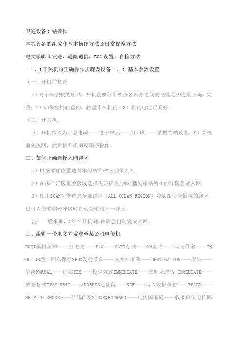
卫通设备C站操作掌握设备的组成和基本操作方法及日常保养方法电文编辑和发送,遇险通信,EGC设置,自检方法一、1 开关机的正确操作步骤及设备一、2 基本参数设置(一)开机前检查1)对于新安装的船站,开机前要仔细检查各部分之间的电缆是否连接正确、完整;2)如果使用软盘的,软盘不在机内;3)机内电池已充好。
(二)开关机。
1)开机依次为:总电源——电子单元——打印机——数据终端设备;2)关机前先脱网,然后按开机的反顺序操作。
二、如何正确选择入网洋区1)根据船舶位置选择本船所在洋区登录入网;2)在多个洋区重叠区域选择需要接收的MSI播发岸站所在的洋区登录入网;3)使用SCAN功能选择全部洋区(ALL OCEAN REGION)登录在信号最强的洋区,也可以使船舶跨洋区时自动登录到下一洋区。
注:一般来讲,C站在开机5秒钟后会自动完成入网。
三、编辑一份电文并发送至某公司电传机EDIT编辑菜单——打电文——F10——SAVE存储——NM命名——写文件名——IN OUTLOG盘、回车保存SEBD发射菜单——文件在屏幕——DESTINATION——岸站——等级NORMAL——证实YES——投递方式IMMEDIATE——立即发送否 IMMEDIATE——数据格式ITA2 5BIT——ADDRESS地址薄——NEW——写入收报单位——TELEX——SHIP TO SHORE——存储转发STORE&FORWARD——电传国家码——收报单位电传码——收报单位电传应答码——回车——选用SELECT——发射TRANSMIT回车。
(08533057 COSCO CN上远公司电传机号码)四、编辑一份电文并发送公司主管的E-mail邮箱EMAIL的发送准备:首先在地址薄编辑好地址。
用NEW ASCII码编辑EMAIL文件,EMAIL 的电文标题格式很重要,每个岸站或公司的E-mail邮箱都有自己的规定格式,以中散公司人事主管为例:TO:(邮件地址:注意大小写,顶格写,没有空格)SUBJECT: ETA空两行打入文件内容发送方式同发送TELEX船位电报相同,不同的是地址薄部分传输类型为SPECIAL。
80系列质量流量计启动显示和按键操作说明

该资料仅供参考,若有异议,请以随设备附带的操作手册为准 80系列质量流量计启动显示和按键操作说明
操作按键
1. 用于输入、选择减号(-) 键
2. 用于输入、选择加号(+) 键
3. 用于调用功能表、保存的回车键
当同时按下+/- 键时(Esc):
• 逐步退出功能表:
• > 3 s = 取消数据输入并返回到测量值显示
1.
→ 进入功能表 (以显示测量值作为开始) 2.
→ 选择功能组 (例如“OPERATION/ 运行”)
→ 确认选择 3.
→ 选择功能 (例如“LANGUAGE/ 语言”) 4.
→输入密码0080,或者80 (仅限于第一次访问功能表) 按→ 逐步确认输入
→ 更改功能/ 选择 (例如“ENGLISH/ 英语”)
→ 确认选择
5.
→ 逐步返回到测量值显示 6.
> 3 s → 立即返回到测量值显示
启动过程完成后,测量设备开始运行。
各种测量变量和/ 或状态变量出现在显示屏上。
按
键进入菜单,同时按键大于3秒可以随时退出。
DS-80 多普勒计程仪英文说明书

DOPPLER SPEED LOGDS-80Marine Speed and Distance Measuring Equipment (SDME)9-52 Ashihara-cho,WARNING LABELA warning label is attached to theDistributor, Transceiver and TerminalBox. Do not remove the labels. If alabel is missing or is illegible, contacta FURUNO dealer or agent aboutreplacement.RECORD OF MODIFICATIONS IN THIS OPERATOR’S MANUALPub No. Software (Prog. No.) Outline of changes in Operator’s ManualPublicized for submission to type test BSHApr/2000 03I-02J-02K (DS-800, DS-801, DS-810)Publicized for submission to type test BSHJune/2000 6550100003I (DS-800) 6550110003J (DS-801) 6550120003K(DS-810)Modified to conform to IEC 61162-1 Edition 22002/4 DS-800: 6550100004 DS-801: 6550110003 DS-810: 6550120003TABLE OF CONTENTSSPECIFICATIONS.......................SP-1FOREWORD (1)SYSTEM CONFIGURATION (2)PRINCIPLE OF OPERATION (3)REMARKS ON USAGE (4)1 OPERATION OF DISPLAY UNIT.51.1 Controls (5)1.2 Turning the Power On/Off (5)1.3 Adjusting Contrast, Panel Dimmer (6)1.4 Selecting a Display (6)1.5 Main Menu Operation (7)1.6 Distance Run Operation (7)1.7 System Setting (9)1.8 Demonstration Mode......................11 2 OPERATION OF OPTIONALEQUIPMENT (12)2.1 Digital Indicator DS-830, DistanceIndicator DS-840 (12)3 MAINTENANCE,TROUBLESHOOTING (14)3.1 Maintenance (14)3.2 Troubleshooting (15)3.3 Diagnostics, CheckingProgram Number (16)4 DIGITAL INTERFACE(IEC 61162-1 Edition 2) (17)4.1 I/O Sentences (17)4.2 Sentence Description (20)5 PARTS LOCATION ANDPARTS LIST (23)Parts Location (23)Parts List (25)CALIBRATION SHEET (29)MENU OVERVIEW (30)INDEX.....................................Index-1 Declaration of conformityThis page is intentionally left blank.SPECIFICATIONS OF THE DOPPLER SPEED LOGDS-801. GENERAL(1) Speed Range Fore-Aft: -10.0 to +40 knots through-the-water(2) Distance Run 0.00 to 999,999.99 nautical miles through-the-water(3) Working Depth Water depth greater than 3 m beneath the keel.(4) Working Frequency 1.0 MHz(5) Speed Accuracy 1.0% or 0.1 knots whichever is the greater(6) Distance Accuracy 1.0% or 0.1 nm whichever is the greaterNote: A ccuracy is subject to shallow water effects, to the effect of wind, current and tide, and sensor location. Any ultrasonic equipment having the same frequency may interfere with speed measurement. The Doppler Log transducer should be installed apart from the transducers of such kind of equipment.2. DISPLAY UNIT(1) Display Character size 15 or 21 mm H on monochrome LCD(2) IndicationShip’s speed Fore: c**.* knots (+40.0 kt max.)Aft: d**.* knots (-10.0 kt max.)Distance run ******.** nm(3) Other Function Diagnostic check3. DIGITAL INTERFACE(1) Serial SignalOutput: 2 ports; VBW, VLW in IEC 61162-1 (NMEA 0183 Ver 2.0)Input: 1 port; IEC 61162 (NMEA 0183 Ver 2.0)(2) Analog Signal Speed signal for Analog display: 2 port-3.3 mA to 10 mA/ -10 kt to +30 ktAnalog current output: 1 port4 mA to 20 mA/ -10 kt to 30 ktAnalog voltage output: 1 port-3.3 V to 10 V/ -10 kt to 30 kt(3) Distance run output 2 ports; Contact closure each 0.005 nm, forward speed,30 VDC: 0.4 A(4) System Check signal 1 port, 30 VDC: 0.2 A, default: closed4. POWER SUPPLY(1) System Source 100/110/115/200/220/230 VAC:1.5/0.7 A max., 1 phase, 50-60 Hz5. ENVIRONMENTAL CONDITION (IEC 60945)(1) Ambient Temperature -15°C to +55°C (units for protected area)Analog display: 0°C to +50°C(2) Relative Humidity 95% at 40°C(3) Vibration IEC 60945 adopted(4) Category of EquipmentDisplay Unit/Distance indicator/Transceiver Unit:For protected areaTransducer: For submerged use, 600 kPa x 12 hDistributor/Terminal box: For protected area6. COATING COLOR(1) Display Unit Cover: Munsell 2.5GY5/1.5 (light gray), P anel: N3.0 (gray)(2) Distribution Box Munsell 2.5GY5/1.5 (light gray)(3) Transceiver Unit Munsell 2.5GY5/1.5 (light gray)(4) Terminal Box Munsell 2.5GY5/1.5 (light gray)(5) Analog Display Munsell 2.5GY5/1.5 (light gray)7. COMPASS SAFE DISTANCE(1) Display Unit/Digital Indicator/Digital Distance IndicatorStandard: 0.50 m, Steering: 0.40 m(2) Transceiver Unit Standard: 2.05 m, Steering: 1.40 m(3) Distribution Box Standard: 3.10 m, Steering: 2.10 m(4) Terminal Box Standard: 0.65 m, Steering: 0.45 mSAFETY PRECAUTION- There is no unit giving rise to a dose rate > 0.5 mrem/h at 50 mm.- There is no harmful radiation from the screen.- All units of this equipment comply with EMC requirements in IEC 60945, as required by IMO Res. A.813 (19).FOREWORDForewordThank you for purchasing the FURUNODS-80 Doppler Speed Log. We are confident you will discover why FURUNO has become synonymous with quality and reliability.Dedicated in the design and manufacture of marine electronics equipment for half a century, FURUNO Electric Company has gained an unrivaled reputation as a world leader in the industry. This is the result of our technical excellence as well as our worldwide distribution and service network.Please carefully read and follow the safety information and operating and maintenance instructions set forth in this manual before attempting to operate the equipment and conduct any maintenance. Your Doppler speed log will perform to the utmost of its ability only if it is operated and maintained in accordance with the correct procedures.This equipment is designed, produced and documented by FURUNO Electric Co., Ltd., complying with ISO 9001 standards as certified by the Lloyd’s Register of Quality Assurance System. FeaturesThe FURUNO DS-80 displays ship’s speed relative to water, using the Doppler principle; ship’s speed is measured by detecting the Doppler shift frequency from the signal returned from the watermass.The output is interfaced with ARPA, AIS, and other shipborne equipment in IEC 61162-1 format.The main features of the DS-80 are• Simple operation. In most cases all that is required to display ship’s speed is to turn on the equipment.• Pair-beam system effectively reduces error caused by pitching. The transducer assembly symmetrically emits two sonic beams, one fore and the other aft. By averaging the Doppler shift in both directions accurate speed data is available under rough sea conditions. • Speed and distance information on the adjustable-contrast LCD display.• Analog display, digital Indicator and digital distance indicator display optionally available.• Conforms to the following standards: IMO A.824(19), as amended by MSC.97(72), IMO A.694(17), IEC 61023, IEC 60945 (3rd edition), IEC 61162-1 (2nd edition)..SYSTEM CONFIGURATIONPRINCIPLE OF OPERATIONThe Doppler speed log measures ship's speed by using the Doppler Effect, which is observed as a frequency shift resulting from relative motion between a transmitter and receiver or reflector of acoustic or electro-magnetic energy. A common example of the Doppler Effect is a train. When a train is approaching, the whistle has a higher pitch than normal. You can hear the change in pitch as the train passes.The DS-80 has a pair-beam, one directed in the fore direction and the other in the aft direction, which emits ultrasonic waves at an angle of θ to the waterline towards ship’s fore and aft directions. The frequency of the received signal is then compared with that of the transmitted frequency to measure doppler shift to calculate ship’s speed.The relative motion causes the Doppler shift and the ultrasonic waves reflected at the watermass (plankton or any underwater objects) are received at the frequency of f r = f o + f d where f d is the number of frequency shifts counted at the receiver circuit. To calculate ship’s speed, the following formula is used.V = f d/f o • c/2sinθc: Underwater velocityNote that the sound velocity in water changes with water temperature and water pressure but the DS-80 readout is automatically compensated for change by using a temperature sensor.Vθf of r = f o + f dWATERMASSSEASURFACEREMARKS ON USAGERemarks on UsageThe DS-80 measures ship’s speed by detecting the Doppler shift frequency of the echo reflected by a watermass (water layer containing plankton and other micro-organisms) located within the measuring area, which is usually about 2 m. In some instances, however, no signal is returned because of too few plankton in the sensing depths. This phenomenon can occur in particular areas in particular seasons. The probable cause is the plankton are lying in deep water because an ice-melted cold water mass covers the sea surface. Similar cases may also occur in a freshwater lake. Under these circumstances the DS-80 will not show the correct ship’s speed.Conditions Affecting the Accuracy(with ref to IMO A.824/3.3)The Doppler speed log DS-80 is designed for reliable and accurate performance through FURUNO’s long experience and advanced technology. It operates on the best choice of system frequency and power output. As far as the sonic energy is used, the performance (accuracy) may be reduced or even lost under:•rough weather (may be sea state 6 or severer)•improper location of sensor, e.g., too close to the propeller, thrusters, drain tubes, echo sounder transducer•depth under the keel if less than 3 m The accuracy will not be affected by:•- water temperature (sound velocity)•salinity•pitch/roll ±10°Beware of Transducer Location The transducer may be damaged if it hits the dry dock blocks. Take the following measures to prevent damage to the transducer.1.Before delivering the ship, draw up asuitable docking plan taking intoaccount the dimensions and location ofthe transducer. Store the plans onboard the ship.2.Place the dry dock blocks according tothe plan.3.Have a diver check the positionbetween the transducer and the blocksbefore removing the water. Confirm that the transducer will not touch the blocks.1 OPERATION OF DISPLAY UNIT1.1ControlsOpens/closes the menu.Selects display; speed plus distance or speed.Registers options on menus.OmnipadSelects items, options on menus.1.2Turning the Power On/Off1.2.1Power onPress the [POWER] switch to turn on the equipment. The last-used display appears.The example below shows the speed and distance run.SpeedDistance RunNote: STW means Speed Through Water. This indication flashes when transducer temperature,which can be monitored on the TEST display (see page 16), is abnormal. This means speed accuracy is less than stated in the specifications.1.2.2Power offPress the [POWER] switch to turn the power off.Note: Keep the DS-80 energizedcontinuously unless it fails. Turning off the DS-80 may cause an inconvenience in associated equipment, such as a radar.1.3Adjusting Contrast, PanelDimmer1.3.1Contrast1.Press the [*] key to open the contrastadjustment dialog box.2.Press the Omnipad at or to adjustthe contrast. The setting range is 0 to 63 and the default setting is 48.3. Press the [ENT] key.Note: The contrast is automatically set to default (48) when the power is turned on.1.3.2Panel dimmer1. Press the [DIM] key to show the dimmeradjustment dialog box.2. Press the Omnipad at or to adjustthe dimmer. The setting range is 1 to 8and the default setting is 4.3. Press the [ENT] key to conclude.Note: The [DIM] key is inoperative when dimmer is controlled externally.1.4Selecting a DisplayPress the [DISP] key to select display desired. Each time the key is pressed the display shows speed and distance run or speed alone as below.SpeedDistanceRunDirection: Fore•Arrow indicates direction: indicates fore;, aft.•The distance run indication shows the total distance run in forward speed only.•The distance run is backed up when the power is turned off.Note: Speed error may occur in rough seas because of air bubbles, etc.When speed error occurs, the speed indication freezes, and “KT” is highlighted and blinks. If speed error continues more than 30 seconds, the speed indication changes to **.*.1.5Main Menu OperationFunctions of the DS-80 are selected through the menu.1.Press the [MENU] key to open themenu.2.Press the Omnipad at or to selecta menu item (current selection ishighlighted) and press the [ENT] key.For example, when DISTANCE RUNDISPLAY is selected the followingdisplay appears. Distance run is a formof contact closure, 200 pulses/nm. Toselect IEC 61162 sentence, seeparagraph 1.6.1.3.Press the Omnipad at or to selectthe menu item desired and press the[ENT] key. For example select RESET.4.Press the Omnipad at or to selectthe menu option desired and press the[ENT] key.5.Press the [MENU] key twice to close themenu. (Some menus require only asingle pressing of the [MENU] key.)To enter numerical dataSome menus require input of numeric data. This is done with the Omnipad.1.Select the digit or sign (+ or -) to changewith or on the Omnipad. (Thecursor shows the digit or sign selected.)2.Enter a figure at each digit by hitting theOmnipad at or . The examplebelow shows the DISTANCE RUNDISPLAY menu, where you may adjustthe distance run indication for SET.Cursor3.Press the [ENT] key to conclude.1.6Distance Run Operation The operator may adjust and reset the distance run indication and select display method.1.6.1Selecting display methodThe default setting provides for independent display and adjustment of the distance run indication on all displays (display unit, Digital Indicator, distance indicator).To show the same distance run indication on all displays do the following:1.Press the [MENU] key to open themenu.2.Press the Omnipad at to selectDISTANCE RUN DISPLAY and pressthe [ENT] key.3.Select DATA DISPLAY and press the[ENT] key.4.Press to select IEC 61162(VLW)and press the [ENT] key.5.Press the [MENU] key twice to close themenu.1.6.2Adjusting distance runDistance run can be changed when the menu item DATA DISPLAY is selected to CONTACT CLOSURE. It may also be changed only at the display unit when IEC 61162(VLW) is selected. .1.Press the [MENU] key to open themenu.e to select DISTANCE RUNDISPLAY and press the [ENT] key.3.Select SET and press the [ENT] key.The cursor circumscribes the leftmostdigit of the distance run figure.Cursor4.Press the Omnipad at or to selectthe digit to change.5.Press the Omnipad at or tochange value. The setting range is 0.00 nm to 999999.99 nm.6.Press the [ENT] key followed bypressing the [MENU] key twice toconclude your selection and close themenu.1.6.3Resetting distance run to zeroDistance run can be reset to zero when the menu item DATA DISPLAY is selected to CONTACT CLOSURE. It may also be reset to zero only at the display unit when IEC 61162(VLW) is selected.1.Press the [MENU] key to open themenu.2.Press the Omnipad at to selectDISTANCE RUN DISPLAY and pressthe [ENT] key.3.Select RESET and press the [ENT] key.4.Press the Omnipad at to select ON.5.Press the [ENT] key to finish and pressthe [MENU] key twice to close the menu.The distance run indication reads 0.00.1.7System SettingThe system setting provides thefundamental parameters for intended performance of the DS-80.1.7.1Displaying the system menu1.Press the [MENU] key to open themenu.2.Select SYSTEM MENU and press the[ENT] key.1.7.2Ship speed averageWind and currents affect ship’s speed, and speed data is averaged over the time period set on this menu. Increase the speed averaging period if the speed reading is unstable.1.Open the SYSTEM MENU.2.Select SHIP SPEED AVG and press the[ENT] key.3.Select averaging time period desiredamong 15, 30, 45 and 60 seconds.4. Press the [ENT] key.5. Press the [MENU] key twice to close themenu.1.7.3Speed offset (calibration)Calibration of any speed log is necessary through the sea trials during thecommissioning tests. Fill in the calibration sheet which is on page 25 of this the resultant data to calculate speed offset and enter it as below. The setting range is -25.0% to +25.0%.1.Open the SYSTEM MENU.2.Select SPEED OFFSET and press the[ENT] key.3.Select the digit to change with orand change the value with or on the Omnipad.4.Press the [ENT] key.5.Press the [MENU] key twice to close themenu.1.7.4Tracking depthDoppler shift measuring depth in the DS-80is 2 m at default. If the speed readout is unstable due to air bubbles near the ship’s hull, increase or decrease the track depth to stabilize the readout. The setting range is 1.0 m to 9.9 m.1. Open the SYSTEM MENU.2.Select TRACK DEPTH and press the[ENT] key.3.Select the digit to change or andchange the value with or on theOmnipad.4.Press the [ENT] key.5.Press the [MENU] key twice to close themenu.1.7.5Transducer offsetSets the deviation angle of the transducer’s orientation with reference to the ship’s longitudinal axis. This is done at installation; no user adjustment is necessary.1.7.6Speed data selectionWhen the DS-80 fails to work as an SDME, the display unit can be used as a monitordisplay tool for a GPS speed or other equipment measuring the ship’s speed.1.Open the SYSTEM MENU.2.Select SPD DATA SELECT and pressthe [ENT] key.3.Select the option GPS and press the[ENT] key.4.Press the [MENU] key twice to close themenu.See the illustration below for speed display information. If the speed displayed is unstable perform the check described in paragraph 3.2.Doppler speed GPS speedGPS-measured"AUTO" position indicates a Doppler speed (SDME) but if the DS-80 fails, a GPS speed will be indicated.Note 1: If the log speed fails, the display unit reads a GPS speed, but speed data will not be output to other equipment.Note 2: Doppler speed is used to calculate speed when both DOPPLER and GPS are abnormal in AUTO.1.7.7System menu 2The System Menu 2 contains the diagnostic test and selection of dimmer control and display language.1.Press the [MENU] key to open themenu.2.Select SYSTEM MENU 2 and press the[ENT] key.TEST : Checks the equipment for proper operation. For further details see Chapter 3.DIMMER: See paragraph NG.: Selects the language to use in menus, English or Japanese.1.8Demonstration ModeThe demonstration mode outputs theDoppler speed signal to external equipment.This checks if the signal is being correctly output. )1.Press the [MENU] key to open themenu.2.Select DEMO and press the [ENT] key.3.Select SPEED and press the [ENT] key.4.Select the digit to change with or .e or to set. (The setting rangeis-10.0 to +40.0 kt, and the default setting is +10.0 kt.)6.Press the [ENT] key.7.Press the [ENT] key to open the DATADISPLAY menu.8.Press to select ON and press the[ENT] key.9. Press the [MENU] key twice to close themenu.The indication “DEMO” appears at the top right-hand corner when the demo mode is on. To turn off the demonstration display,show the DEMO menu and set SPD to OFF.Demonstration mode "ON"2 OPERATION OF OPTIONALEQUIPMENTThe Digital Indicator DS-830 and Distance Indicator DS-840 have the same controls as the display unit. This chapter explains the features which are not shared with the display unit.2.1Digital Indicator DS-830, Distance Indicator DS-8402.1.1Selecting a displayPress the [DISP] key to select the display mode. Each time the key is pressed the display shows speed plus distance run or speed alone as below.SpeedDistance RunDigital Indicator DS-830SpeedDistance RunDistance Indicator DS-8402.1.2Menu operation1. Press the [MENU] key to show thedisplay below.2.For details refer to the following:DISTANCE RUN DISPLAY: See paragraph 1.6.SYSTEM MENU 2: See 1.7.7 System Menu 2.2.1.3Adjusting dimmer andcontrastSee paragraph 1.3.ANALOG DISPLAY UNITCORRECTION DIAGRAM AT EXTREME TEMPERATURESDoppler Speed Log DS-80CORRECTION FACTOR FOR ANALOG DISPLAY MF-22A-1Example:If the analog speedometer reads 14.2 kt at a temperature of –15°C, the correct speed through the water is 15 kt. Failure of correction in low temperature can result in a maximum error of –0.8 kt or 5.3% for 14.2 kt readout. IMO limit of ±2% is exceeded over 10.0 – 30.0 kt reading but correction by this graph brings a correct measurement.At +55°C, an error of +0.0 kt (+2.7%) occurs at a speed of 30 kt; no other point IMO limit of ±2% is exceeded.When the digital display and analog display readouts are different, take precedence of the digital readout. At temperatures 0°C to 50°C, the speedometer never exceeds the IMO limits.3 MAINTENANCE, TROUBLESHOOTING3.1 Maintenance3.1.1 Preventive maintenanceCheck the following points regularly to maintain performance.• Check that the connectors on all units of the system are firmly fastened and free of rust. Clean if soiled or corroded.• Check that all ground wires are tightly fastened.• Dust and dirt on the display unit including the screen may be removed with a soft cloth. Do not use chemical cleaners to clean the display unit; they can remove paint and markings.3.1.2 Transducer maintenanceMarine life (barnacles, etc.) adhering to the transducer face will reduce sensitivity. Periodically remove any marine life from the transducer face with fine sandpaper or a piece of wood.3.1.3 Fuse replacementFuses in the units of the system protect the electrical circuitry from burning by overcurrent. If the equipment cannot be energized check the fuse in the powercable connected to the display unit. Locate the cause before replacing the fuse.UnitRating,QtyType,Code No.LocationDisplayUnit1A,2 pcs.FGMB 1A125 VAC,000-114-805Fuseholder inpowercableDistributionBox3A,2 pcs.FGBO 3A250 VAC000-549-021TransceiverUnit1A,2 pcs.FGBO 1A250 VAC,000-549-019Insideunit3.2 TroubleshootingThis section provides troubleshooting procedures. Advanced level troubleshooting should be done by referring to the Service Manual (optional supply).If any abnormal speed indication continuescontact your dealer for advice.3.3 Diagnostics, CheckingProgram NumberThe diagnostic facility checks the ROM, RAM, SIO and displays program ID.1. Press the [MENU] key to open themenu.2. Select SYSTEM MENU2 and press the[ENT] key.3. Press the [ENT] key. The followingdisplay appears.4. Press the [ENT] key to start the test. Ina few moments the display shouldchanges as shown at the top of theadjacent column.The ROM, RAM and SIO (if specialconnector is used) are checked forproper operation and the results shown as OK or NG (No Good). For NG,contact your dealer for advice.The program number also appearshere.“PUSH KEY” is highlighted, promptingyou to check the controls. Operate anycontrol (except the [POWER] switch)within five seconds. The name of theactivated control appears on screen if it is operating normally. Note that if nocontrol is operated within five seconds,the equipment automatically beginschecking the LCD.No. of times testconsecutivelyexecuted.6550100003I = Display Unit DS-8006550110003J = Distribution Box DS-8016550120003K = Transceiver Unit DS-810Transducer temperatureX appears whentemperaturesensor isabnormalControl operated and indicationControl IndicationUPDOWNLEFTRIGHTMENU MENUENT ENTDISP DISPDIM DIM* *5. The equipment automatically checksthe LCD, displaying the following inorder.6. The test repeats itself. T o stop the test,turn the power switch off and on again.4 DIGITAL INTERFACE (IEC 61162-1Edition 2)4.1 I/O SentencesInput sentences of IEC61162_RX portGGA, VTGOutput sentences of IEC61162_TX1, IEC61162_TX2 portsVBW, VLW (Talker: VD)Transmission interval3 s for VBW; 1 s for VLWData transmissionData is transmitted in serial asynchronous form in accordance with the standard referenced in 2.1 of IEC 61162-1. The first bit is a start bit and is followed by data bits,least-significant-bit as illustrated below.The following parameters are used:Baud rate: 4800Data bits: 8 (D7 = 0), parity noneStop bits: 1D0 D1 D2 D3 D4 D5 D6 D7Startbit bitSchematic diagramsIEC61162 RX portDS-801Load requirements as listener Isolation: OptocouplerInput Impedance: 44 ohms Max. Voltage: ±2.6V Threshold: 4 mAIEC61162 TX1 portOutput drive capability Max. 20 mAIEC61162 TX2 portDS-801TB3Output drive capability Max. 20 mA4.2 Sentence DescriptionGGA - Global positioning system (GPS) fix dataTime, position and fix related data for a GPS receiver.Note: Item Only GPS quality indicator and antenna altitude above/below are used.VTG - Course over ground and ground speedThe actual course and speed relative to the ground.$--VTG,x.x,T,x.x,M,x.x,N,x.x,K,a*hh<CR><LF>| | | | | | | | | || | | | | | | | | +------- 6| | | | | | | | +--------- 5| | | | | | +--+----------- 4| | | | +--+----------------- 3| | +--+----------------------- 2+--+----------------------------- 11. Course over ground, degrees true2. Course over ground, degrees magnetic3. Speed over ground, knots4. Speed over ground, km/h5. Mode indicator(see note)6. ChecksumNOTE Positioning system Mode indicator:A = AutonomousD = DifferentialS = SimulatorN = Data not validThe positioning system Mode indicator field shall not be a null field. Note: Speed, course degrees magnetic and course degrees true not used.VBW - Dual ground/water speedWater-referenced and ground-referenced speed data. $--VBW,x.x,x.x,A,x.x,x.x,A,x.x,A,x.x,A*hh<CR><LF>| | | | | | | | | | || | | | | | | | | | +--- 11| | | | | | | | | +----- 10| | | | | | | | +-------- 9| | | | | | | +----------- 8| | | | | | +-------------- 7| | | | | +----------------- 6| | | | +-------------------- 5| | | +------------------------ 4| | +--------------------------- 3| +------------------------------ 2+---------------------------------- 11. Longitudial water speed, knots2. Transverse water speed, knots3. Status: water speed, A=data valid V=data invalid4. Longitudial ground speed, knots5. Transverse ground speed, knots6. Status: ground speed, A=data valid V=data invalid7. Stern transverse water speed, knots8. Status: stern water speed, A=data valid V=data invalid9. Stern transverse ground speed, knots10. Status: stern ground speed, A=data valid V=data invalid11. ChecksumNotes1. Longitudinal speed: “-” astern.* Not used.VLW - Distance travelled through the waterThe distance travelled, relative to the water.$--VLW,x.x,N,x.x,N*hh<CR><LF>| | | | || | | | +--------- 3| | +--+----------- 2+--+----------------- 11. Total cumulative distance, nautical miles2. Distance since reset, nautical miles3. Checksum。
船舶设备操作规程

船舶设备操作规程
《船舶设备操作规程》
船舶设备操作规程是船舶上的重要管理制度,它对船舶设备的操作和使用进行了详细的规定,旨在确保船舶设备的安全使用和操作。
船舶设备操作规程是船舶上实施的一项重要制度,在船员操作设备时必须严格遵守规定,确保船舶设备的正常运行和船舶的安全。
船舶设备操作规程包括了船舶上各种设备的操作细则,包括主机、辅机、舵机、电器设备、润滑设备等。
其中,主机和辅机是船舶上最为重要的设备,对其操作和使用规定尤为严格。
船舶设备操作规程明确规定了主机、辅机的操作步骤、注意事项、常见故障处理方法等,以确保设备的安全、稳定和高效运行。
此外,船舶设备操作规程还规定了船舶上设备的日常维护、保养和检修制度。
船舶设备的正常维护和保养对于确保设备的长期安全运行至关重要,因此规程中对于设备的日常维护和保养进行了详细规定,并制定了相应的检修计划和制度。
船舶设备操作规程不仅是保障船舶设备安全运行的一项制度,也是一项保障船员生命财产安全的重要制度。
船员在接受相应的培训后,必须严格遵守规程,严守船舶设备的操作规定,做到履职尽责,确保船舶设备的安全运行和船员的安全。
船舶设备操作规程的制定和实施,对于保障船舶设备的安全、高效运行具有重要意义,是船舶管理中不可或缺的一部分。
只
有加强船舶设备操作规程的制度管理,掌握船舶设备的操作技术,做到预防为主,确保船舶设备的安全运行,才能保证船舶的安全航行和货物的安全运输。
第五节 船用计程仪.

返回
25
水压式
V
航海仪器(电)
返回
26
fr
f
0
1
2
v c
cos
2 v 2 cos 2
c
2 v 3 cos 3
c
fr
f
0
1
2
v c
cos
f0
2
f
0
v c
cos
f
fr
f0
2
f
0
c 声速
不能取俯角为90度,即不能垂 直发射.垂直不产生多普勒效应
11 航海仪器(电)
发射俯角500米/秒,但不是常量, 受温度,含盐量和静水压力的 影响。
12 航海仪器(电)
第三节 多普勒计程仪
五、双波束多普勒计程仪
单波束多普勒计程仪存在的问题: 非线性误差
Eg BlV cos
航海仪器(电)
交流磁感应强度
6
电磁计程仪是相对计程仪,只 相对于水的计程仪,能反映出 风对船舶速度的影响。
例:船无风无流时船速为10节, 现顺风顺流各为2节,则电磁计 程仪显示的航速应为多少?
7 航海仪器(电)
第三节 多普勒计程仪
单波束多普勒计程仪的测速与计程原理, 存在的问题。
u
sin
2 f
f0 4
fv0cvocsos
u sin cos
c
cc
4 f0v cos
c
usin usin
船载雷达操作规程(3篇)
第1篇一、适用范围本规程适用于所有船载雷达设备的操作与管理,包括雷达系统、显示器、控制单元等组成部分。
二、操作前准备1. 检查雷达设备是否完好,电源线、天线线等连接是否牢固。
2. 确认雷达设备的操作手册、维修保养手册等相关资料齐全。
3. 了解雷达设备的性能参数、操作流程和安全注意事项。
三、操作流程1. 开启雷达设备(1)打开电源开关,确保雷达设备正常启动。
(2)检查雷达显示屏是否正常显示,如出现异常,应立即关闭电源,查找原因并修复。
2. 调整雷达工作参数(1)根据实际需求调整雷达的工作频率、增益、海浪抑制等参数。
(2)调整雷达扫描速度,确保雷达能够及时捕捉到目标。
3. 雷达设备操作(1)启动雷达设备后,根据雷达显示器的提示,选择合适的工作模式,如A、B、C、D等。
(2)观察雷达显示屏上的目标信息,包括目标距离、方位、速度、大小等。
(3)根据实际情况调整雷达设备的各项参数,如增益、海浪抑制等,以提高雷达的探测能力。
4. 雷达设备关闭(1)在完成雷达操作后,关闭雷达设备的电源开关。
(2)确保雷达设备周围环境整洁,无杂物。
四、安全注意事项1. 操作雷达设备时,应严格遵守操作规程,确保设备正常工作。
2. 在雷达设备附近工作时,应注意防止设备受到损坏。
3. 雷达设备操作人员应具备一定的电子、航海等相关知识,熟悉雷达设备的性能和操作方法。
4. 在雷达设备操作过程中,如发现异常情况,应立即停止操作,查找原因并修复。
5. 雷达设备操作人员应定期参加雷达设备操作培训,提高操作技能和安全意识。
五、维护保养1. 定期对雷达设备进行清洁,保持设备内部和外部清洁。
2. 检查雷达设备的电源线、天线线等连接是否牢固,如有松动,应及时紧固。
3. 定期对雷达设备进行性能测试,确保设备正常运行。
4. 根据雷达设备的维修保养手册,定期进行维护保养,确保设备处于良好状态。
六、总结船载雷达操作规程是确保雷达设备正常工作、提高船舶航行安全的重要保障。
船舶地面站操作手册驾驶室仪器操作规程

INMARSAT-C船舶地面站操作规程
INMARSAT船舶地面站操作规程
中/高频/SSB无线电装置操作规程
甚高频无线电装置操作规程
高频无线电装置操作规程
NVATEX航行警告接收机操作规程
气象传真机操作规程
AIS船用全球自动识别系统操作规程
回声测深仪操作规程
GPS接收机操作规程
自动操舵仪操作规程
电罗经操作规程
磁罗经操作规程
电磁记程仪操作规程
VDR船载航行数据记录仪操作规程
操作规程
注意事项备注
双向无线电话操作规程
SART 操作规程
EPIRB 操作规程
INMARSAT-F 操作规程
RADAR 雷达操作规程
RADAR雷达操作规程
雷达操作规程
舵机操作程序
1、通知机舱舵机供电。
2、打开舵机开关,选择舵机组。
3、选择操纵方式,随动方式。
4、转动舵轮试验舵角指示。
5、最后舵角指示回零。
6、舵机备好。
应急舵操作规程。
测量船作业安全操作规程

行业资料:________ 测量船作业安全操作规程单位:______________________部门:______________________日期:______年_____月_____日第1 页共6 页测量船作业安全操作规程为加强测量船舶驾驶及轮机的安全管理,避免和减少事故的发生,在事故发生后将损失降到最低限度,根据有关规定,制订如下测量船安全操作规程。
一、开船前设备检查1、开航前检查舵机是否正常。
2、检查航行灯具是否正常发光。
3、检查燃润料是否带足。
4、消防设备是否正常。
5、救生设备是否正常。
6、系泊缆绳是否正常。
7、测量机电设备是否能正常运转。
二、航行途中1、机驾人员严禁酒后上岗。
2、在船人员必须穿戴好救生衣3、机驾人员必须持证上岗。
4、航行途中必须加强瞭望。
及时掌握航标、航道、航行信号,水文、气象、来往船舶动态和周围环境,结合本船操纵性能采取一切有效措施确保航行安全。
5、正确使用和操纵助航设备,并掌握在使用中发生故障的应急措施。
6、严格按照设备说明书的规定及机电设备的操作规程进行操作管理,确保各项设备技术状况良好,运转情况正常。
第 2 页共 6 页7.严格遵守环境保护法及港章有关规定,认真做好机舱油类和污水处理,防止污染水域。
8、值班机驾员应当坚守岗位,认真操作,严格执行《中华人民共和国内河避碰规则》和其它有关航行规章制度。
9.船舶驾机人员必须按规定认真填写航行日志及轮机日志,保证记录的真实性完整10、舶驻港期间认真做好值班工作,做好船舶及仪器清洁,使船舶有良好的船容船貌。
测风员岗位安全操作规程一、入井前应对所用的仪表进行检查,保证完好。
二、入井前必须根据任务带好所用的风表、秒表、瓦斯检定器、皮尺、记录本等有关仪器。
携带和使用仪器时,必须轻拿轻放,避免碰撞。
三、井下测风地点的选择1、测风地点应选择在;矿井、一翼、水平的进回风巷,采区进、回风巷,采掘工作面进、回风巷,井下爆破材料库和主要用风硐室,以及其他需要测风的地点。
DS-80简要操作指南
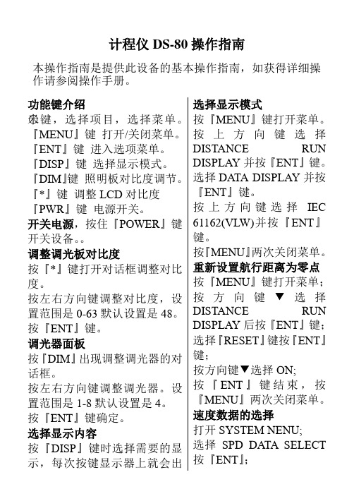
计程仪DS-80操作指南本操作指南是提供此设备的基本操作指南,如获得详细操作请参阅操作手册。
功能键介绍○米键,选择项目,选择菜单。
『MENU』键打开/关闭菜单。
『ENT』键进入选项菜单。
『DISP』键选择显示模式。
『DIM』键照明板对比度调节。
『*』键调整LCD对比度『PWR』键电源开关。
开关电源,按住『POWER』键开关设备。
调整调光板对比度按『*』键打开对话框调整对比度。
按左右方向键调整对比度,设置范围是0-63默认设置是48。
按『ENT』键。
调光器面板按『DIM』出现调整调光器的对话框。
按左右方向键调整调光器。
设置范围是1-8默认设置是4。
按『ENT』键确定。
选择显示内容按『DISP』键时选择需要的显示,每次按键显示器上就会出选择显示模式按『MENU』键打开菜单。
按上方向键选择DISTANCE RUN DISPLAY并按『ENT』键。
选择DATA DISPLAY并按『ENT』键。
按上方向键选择IEC 61162(VLW)并按『ENT』键。
按『MENU』两次关闭菜单。
重新设置航行距离为零点按『MENU』键打开菜单;按方向键▼选择DISTANCE RUN DISPLAY后按『ENT』键;选择『RESET』键按『ENT』键;按方向键▼选择ON;按『ENT』键结束,按『MENU』两次关闭菜单。
速度数据的选择打开SYSTEM NENU;选择SPD DATA SELECT 按『ENT』;现速度和行驶距离或者是单一的速度。
主菜单操作按『MENU』键打开菜单。
按上下方向键选择需要的项目并按『ENT』。
按『MENU』键两次关闭菜单(有的菜单仅需要按一次)。
选择数位符号(+或—)替换菜单上左右方向键。
外部输入用上下方向键选中每一个数字。
按『ENT』确定。
选择选项GPS或DOPPLER按『ENT』;按『MENU』两次关闭菜单。
船上雷达设备操作规程(3篇)
第1篇一、引言雷达设备是现代船舶安全航行的重要辅助设备,它能有效提高船舶在复杂气象、能见度不良等条件下的航行安全性。
为确保雷达设备的安全、有效运行,特制定本操作规程。
二、适用范围本规程适用于所有配备雷达设备的船舶,包括但不限于客船、货船、油轮、化学品船等。
三、操作人员要求1. 操作人员应具备雷达设备操作资格,熟悉雷达设备的基本原理、性能和操作方法。
2. 操作人员应了解船舶的航行路线、航行计划和周围环境。
3. 操作人员应掌握雷达设备故障处理和应急操作程序。
四、操作步骤1. 启动雷达设备(1)打开雷达设备电源开关。
(2)确认雷达设备工作正常,显示屏亮度适中。
(3)调整雷达天线位置,使其指向船舶前方。
2. 调整雷达参数(1)调整雷达发射功率,确保雷达设备正常工作。
(2)调整雷达波束宽度,根据航行需求选择合适的波束宽度。
(3)调整雷达扫描速度,确保雷达图像稳定。
(4)调整雷达距离标尺,使其与实际航行距离相符。
3. 观察雷达图像(1)观察雷达图像,了解周围船舶、障碍物和危险区的分布情况。
(2)分析雷达图像,判断船舶与周围物体的距离、方位和速度。
(3)根据雷达图像,调整船舶航向和航速,确保航行安全。
4. 故障处理(1)如雷达设备出现故障,应立即停止操作,并向船长报告。
(2)根据故障现象,采取相应措施进行处理,如关闭雷达设备、检查线路、更换备件等。
(3)在故障排除前,应使用其他导航设备辅助航行。
五、应急操作1. 雷达设备失效(1)立即通知船长,启动应急导航程序。
(2)使用其他导航设备,如GPS、罗盘等,确定船舶位置。
(3)根据实际情况,调整船舶航向和航速。
2. 雷达设备故障(1)在确保船舶安全的前提下,尽量使用雷达设备进行导航。
(2)如雷达设备故障无法修复,应立即通知船长,采取应急措施。
(3)根据船长指示,使用其他导航设备或依靠船员的航行经验进行航行。
六、注意事项1. 操作雷达设备时,应保持专注,注意观察雷达图像。
自动计数机操作规程(3篇)
第1篇一、概述自动计数机是一种用于自动统计物品数量的设备,广泛应用于生产、物流、零售等行业。
为确保操作人员正确、安全地使用自动计数机,特制定本操作规程。
二、操作前的准备1. 检查设备外观:确保计数机无损坏,各部件齐全,电源线、数据线等连接正常。
2. 确认电源电压:确保设备接入的电源电压符合设备要求。
3. 清理工作区域:保持工作区域整洁,避免杂物影响计数机运行。
三、操作步骤1. 开机:将计数机电源线插入电源插座,按下开机按钮,待设备启动完毕。
2. 调整计数模式:根据计数需求,选择合适的计数模式(如计数、累加、减去等)。
3. 设定计数范围:根据物品数量,设定计数范围,确保计数准确。
4. 放置物品:将待计数的物品放置在计数机上,确保物品平稳、整齐。
5. 开始计数:按下开始按钮,计数机开始自动计数,操作人员观察计数结果。
6. 检查计数结果:在计数过程中,操作人员需随时检查计数结果,确保准确无误。
7. 结束计数:完成计数后,按下停止按钮,计数机停止工作。
8. 数据导出:如需将计数数据导出,连接数据线,选择导出格式,将数据导出到电脑或其他设备。
四、操作注意事项1. 操作人员需熟悉设备操作流程,确保正确操作。
2. 严禁在设备运行过程中添加、移除物品,以免影响计数准确性和设备安全。
3. 操作过程中,如发现设备异常,立即停机检查,待问题解决后再继续操作。
4. 严禁私自拆卸、改装设备,如需维修,请联系专业人员进行。
5. 操作结束后,关闭设备电源,清理工作区域,保持设备整洁。
五、维护与保养1. 定期检查设备外观,确保无损坏。
2. 保持计数机内部清洁,定期清理计数机内部积尘。
3. 定期检查电源线、数据线等连接线,确保连接牢固。
4. 如设备出现故障,请及时联系专业人员进行维修。
六、安全注意事项1. 操作人员需佩戴防护手套、眼镜等安全防护用品。
2. 操作过程中,注意保持设备周围安全距离,避免意外伤害。
3. 严禁操作人员单独操作设备,确保有其他人员在场监督。
各种GMDSS设备操作规程

各种GMDSS设备操作规程GMDSS(全球海上遇险及安全系统)是国际海事组织(IMO)制定的一套海上通信和与救助系统。
GMDSS设备包括雷达、无线电、卫星通信设备等,具体的操作规程如下。
1.GMDSS设备的操作前准备:在操作GMDSS设备之前,应进行以下准备工作:-熟悉设备的操作手册,了解各种技术规格和参数;-检查设备的正常工作状态,确保无任何故障;-检查电池电量,确保有足够的电量支持设备的使用;-清洁设备表面,确保设备运行时没有任何障碍物。
2.GMDSS设备的开机和关机操作:开机操作包括打开电源开关和设备的电源按钮,然后进行设备自检。
在设备自检期间,应注意观察设备是否正常运行,并检查各种状态指示灯是否亮起。
关机操作则是将设备的电源按钮关闭,并切断电源开关。
3.GMDSS设备的频道选择:4.GMDSS设备的通信方式:GMDSS设备可以通过语音或数据通信进行通信。
语音通信可以使用设备上的麦克风进行,而数据通信则通常是通过附加设备或电缆进行连接。
在通信过程中,需要遵守国际通信协议和规范,尽量使用正式的语言和专业术语。
5.GMDSS设备的紧急报警操作:当船舶发生紧急情况时,应立即发出紧急报警信号,以便得到及时的援助。
紧急报警信号可以通过GMDSS设备上的专用按钮或开关进行触发,也可以通过相应频道发送特定的紧急信号。
在发送紧急信号之前,需要确保所在区域的其他船只和岸基站都已收到信号。
6.GMDSS设备的故障排除:综上所述,GMDSS设备的操作规程包括准备工作、开机和关机操作、频道选择、通信方式、紧急报警操作和故障排除等方面。
这些规程有助于确保GMDSS设备的正常运行,并提供及时的通信和救援服务。
船舶设备操作规程

船舶设备操作规程1. 引言船舶设备操作规程是为了确保船舶设备的安全运行而制定的。
船舶设备操作人员必须遵守本规程,熟悉船舶设备操作流程和安全操作要求,以保障船舶的正常运行和船员的个人安全。
2. 船舶设备操作流程船舶设备操作流程是指按照一定的顺序和步骤操作船舶设备的过程。
在操作船舶设备之前,操作人员必须了解设备的结构和功能,并按照以下步骤进行操作:1.开始操作前,确保设备处于停止状态,关闭所有相关的电源和阀门。
2.仔细检查设备的外观和工作环境,确保没有任何异常情况。
3.根据操作手册或相关指导文件,了解设备的操作要点和注意事项。
4.穿戴必要的个人防护装备,如安全帽、防护眼镜、手套等。
5.打开电源或阀门,启动设备,并注意设备的启动过程和反应。
6.在设备运行期间,正常监控设备的工作状态,注意观察设备运行参数和指示器的变化。
7.如遇到异常情况或设备故障,立即停止设备运行,并采取相应的紧急措施进行处理。
8.操作完成后,将设备停止,关闭所有电源和阀门,并进行设备的清洁和维护工作。
3. 安全操作要求为了保障船舶设备操作的安全性,操作人员必须严格遵守以下安全操作要求:1.操作前必须仔细检查设备和工作环境,确保没有任何异常情况,并确保个人安全。
2.操作人员必须熟悉设备的结构、功能和相关操作规程,并按照规程要求进行操作。
3.操作人员必须按照正确的顺序和步骤进行操作,不得随意更改或省略任何步骤。
4.在设备运行期间,操作人员必须时刻监控设备的工作状态,注意观察运行参数和指示器的变化。
5.如遇到异常情况或设备故障,操作人员必须立即停止设备运行,并采取相应的紧急措施进行处理。
6.操作人员在进行设备维护和清洁工作时,必须按照相关规程要求进行,并确保个人安全。
7.操作人员必须严禁在未经许可的情况下擅自操作船舶设备,并严禁拆卸、更改设备部件。
8.操作人员必须定期接受相关培训和考核,以确保操作技能的更新和提升。
4. 事故预防和应急处置船舶设备操作人员必须时刻保持高度警惕,预防事故的发生。
航海仪器的正确使用

浙江交通职业技术学院《航海仪器的正确使用》评估实训指导书任松涛主编戴耀存主审浙江交通职业技术学院海运学院前言《1978年海员培训、发证和值班标准国际公约》(简称STCW公约)于1978年7月7日在国际海事组织总部召开的国际海员培训,发证外交大会中得以通过,我国是该公约的签字国。
1993年,国际海事组织着手对STCW公约进行全面的修改。
1995年6月26日到7月7日,在伦敦国际海事组织总部召开了STCW公约的缔约国大会。
1995年7月7日,包括中国在内的缔约国代表在通过1995年STCW修正案和STCW 规则的1995STCW缔约国大会最终文件上签字。
1995年STCW 修正案和STCW规则已于1997年2月1日生效。
我国政府对STCW公约给予高度重视。
交通部和国家海事局相继颁布了船员考试、发证规则和相应的培训纲要,2004年6月22日交通部第15次部务会议通过了新的《中华人民共和国海船船员适任考试、评估和发证规则》,已于2004年8月1日起施行。
新规则对申考甲类、乙类及丙类三副者在航海仪器的正确使用方面作了详细规定。
《航海仪器的正确使用》评估实训指导书是根据交通部和国家海事局颁布了的《船员考试、发证规则》和相应的培训纲要编写的,适用于甲类、乙类及丙类三副的考前培训。
实训一安许茨系列罗经(航海I型)的正确使用一、目的与要求掌握航海I型罗经的组成及各部分的作用,掌握航海I 型主罗经的组成及各部分的作用,掌握航海I型罗经启动前的准备工作及启动的过程,掌握航海I型罗经使用中的检查事项。
二、设备航海I型陀螺罗经三、组织与实施先教师集中讲解,后分组进行实训四、方法与步骤1.罗经的组成及各部分的作用1)主罗经:指示航向;2)航向记录器:记录航向;3)变流机组:将船电转变成罗经各部分需要的电源;4)变压器箱和报警装置:对罗经进行启动,关闭和监视其工作;5)分罗经:复示主罗经的航向。
2.主罗经的组成及各部分的作用1)灵敏部分:陀螺球;找北、指北;2)随动部分:跟踪灵敏部分一起转动,使航向刻度盘上0°~180°的刻度线与陀螺球主轴南北线始终保持一致;3)固定部分:由罗经桌、罗经箱等组成,提供灵敏部分正常工作的外部条件。
80及83系列质量流量计操作
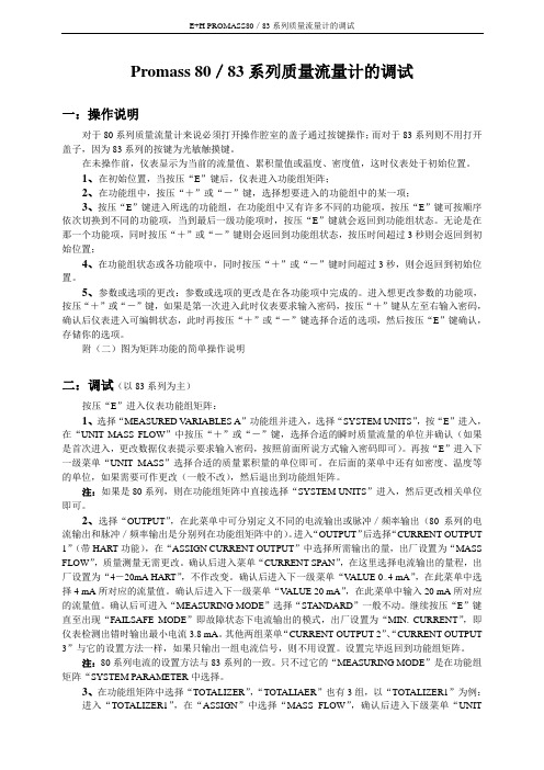
Promass 80/83系列质量流量计的调试一:操作说明对于80系列质量流量计来说必须打开操作腔室的盖子通过按键操作;而对于83系列则不用打开盖子,因为83系列的按键为光敏触摸键。
在未操作前,仪表显示为当前的流量值、累积量值或温度、密度值,这时仪表处于初始位置。
1、在初始位置,当按压“E”键后,仪表进入功能组矩阵;2、在功能组中,按压“+”或“-”键,选择想要进入的功能组中的某一项;3、按压“E”键进入所选的功能组,在功能组中又有许多不同的功能项,按压“E”键可按顺序依次切换到不同的功能项,当到最后一级功能项时,按压“E”键就会返回到功能组状态。
无论是在那一个功能项,同时按压“+”或“-”键则会返回到功能组状态,按压时间超过3秒则会返回到初始位置;4、在功能组状态或各功能项中,同时按压“+”或“-”键时间超过3秒,则会返回到初始位置。
5、参数或选项的更改:参数或选项的更改是在各功能项中完成的。
进入想更改参数的功能项,按压“+”或“-”键,如果是第一次进入此时仪表要求输入密码,按压“+”键从左至右输入密码,确认后仪表进入可编辑状态,此时再按压“+”或“-”键选择合适的选项,然后按压“E”键确认,存储你的选项。
附(二)图为矩阵功能的简单操作说明二:调试(以83系列为主)按压“E”进入仪表功能组矩阵:1、选择“MEASURED V ARIABLES A”功能组并进入,选择“SYSTEM UNITS”,按“E”进入,在“UNIT MASS FLOW”中按压“+”或“-”键,选择合适的瞬时质量流量的单位并确认(如果是首次进入,更改数据仪表提示要求输入密码,按照前面所说方式输入密码即可)。
再按“E”进入下一级菜单“UNIT MASS”选择合适的质量累积量的单位即可。
在后面的菜单中还有如密度、温度等的单位,如果需要可作更改(一般不改),然后退出到功能组矩阵。
注:如果是80系列,则在功能组矩阵中直接选择“SYSTEM UNITS”进入,然后更改相关单位即可。
77m车客渡船测深仪、计程仪换能器故障分析
GUANGDONG SHIPBUILDING 广东造船2020年第1期(总第170期) 建造与修理87作者简介:王小莉(1984-),女,工程师。
主要从事船舶电气设计工作。
收稿日期:2019-03-1577 m 车客渡船测深仪、计程仪换能器故障分析王小莉(广东新船重工有限公司,广州 510111)摘 要:介绍了由广东新船重工有限公司设计建造的77 m 车客渡船测深仪、计程仪换能器的安装技术问题,通过技术分析找到换能器工作故障的原因是船型导致的。
该船为双向纵流首船型,由于水流问题在船底堆积了大量气泡,导致换能器未能在有效的水面上工作,从而造成测深仪、计程仪换能器不能正常的工作,通过改换换能器安装方法解决了故障问题。
关键词:纵流首船舶;测深仪;计程仪;换能器;气泡中图分类号:U665.26 文献标识码:AFault Analysis of Echo Sounder and Speed Log Transducer of77 m Car-passenger FerryWANG Xiaoli( Guangdong Bonny Fair Heavy Industry Limited, Guangzhou 510111 )Abstract: This paper introduces the installation of the echo sounder and speed log transducer of the 77 m car-passenger ferry designed and built by Guangdong Bonny Fair Heavy Industry Limited. Through technical analysis, it finds out that the fault of the transducer is caused by ship type. The ferry has the two-way longitudinal bow, due to the problem of water flow, a large number of air bubbles are accumulated in the bottom of the ferry and the transducer does not work on the effective water surface, which leads to the abnormal operation of the echo sounder and speed log transducer and the unstable display data. The fault is removed by changing the installation method of the transducer.Key words: Vessel with longitudinal-flow bow; Echo sounder; Speed log; Transducer; Air bubble1 前言测深仪是用于探测船舶下方水深和水中障碍物(如沉船、暗礁或浅滩等),并把探测结果记录或显示出来,从而避免船舶搁浅、触礁等事故;计程仪是用于测定船舶航行速度和累计船舶航程的仪器,并将船舶航速、航程信息输出给所需要的设备和部门进行数据处理和显示、记录。
工程船舶操作规程及船员职务
工程船舶操作规程及船员职务规则和岗位责任制汇编二〇一二年一月目录第一部分工程船舶操作规程 (1)第一篇总则 (1)第二篇甲板部操作规程 (2)第一章航行及作业前的准备和检查 (2)第二章离靠作业操作规程 (4)第三章港内航行操作规程 (8)第四章起抛锚作业操作规程 (9)第五章带缆作业操作规程 (10)第六章停泊作业操作规程 (12)第七章油类作业操作规程 (14)第八章拖带及配合作业操作规程 (15)第九章起重船操作规程 (17)第十章打桩船操作规程 (21)第十一章挤密砂桩船操作规程 (24)第十二章抓泥船操作规程 (27)第十三章浮坞(半潜驳)操作规程 (29)第十四章整平船(青平2)操作规程 (34)第十五章方驳操作规程 (37)第十六章泥驳操作规程 (39)第十七章沉箱拖带操作规程 (40)第十八章抓泥船GPS定位系统操作规程 (43)第三篇轮机部操作规程 (45)第一章船用柴油主机操作规程 (45)第二章副柴油机操作规程 (50)第三章液压装置操作规程 (52)第四章发电机配电板操作规程 (55)第五章电动机与控制箱操作规程 (58)第六章电动锚机操作规程 (60)第七章酸性蓄电瓶操作规程 (61)第八章船用油、水泵操作规程 (63)第九章空气压缩机操作规程 (65)第十章船用辅助锅炉操作规程 (67)第十一章起重动力装置操作进程 (70)第十二章打桩动力装置操作规程 (71)第十三章抓泥船动力装置操作规程 (72)第十四章工程船绞车操作规程 (74)第四篇船舶安全作业措施 (75)第一章防风准备与遇风措施 (75)第二章雾航措施 (77)第三章冰区航行措施 (79)第四章防冻、防火、防滑措施 (80)第五章海事与救助措施 (83)第六章救助遇难船的行动 (86)第七章消防 (87)第八章救生 (90)第九章高空、舷外、水上作业规则 (93)第三部分船员职务规则 (94)第一篇总则 (94)第二篇甲板部职务职责 (96)第一章船长(驾长)职务规则 (96)第二章大副(副驾长)职务规则 (99)第三章二副职务规则 (101)第四章三副职务规则 (102)第五章正驾驶职务规则 (103)第六章副驾驶职务规则 (104)第七章报务员职务规则 (105)第八章水手长职务规则 (106)第九章一级水手职务规则 (107)第十章二级水手职务规则 (108)第三篇轮机部职务职责 (109)第一章轮机长职务规则 (109)第二章大管轮职务规则 (112)第三章二管轮职务规则 (114)第四章三管轮职务规则 (115)第五章加油工职务规则 (116)第六章电工职务规则 (117)第三部分船员岗位责任制 (118)第一篇总则 (118)第二篇甲板部岗位责任制 (119)第一章拖轮岗位责任制 (119)第二章起重船施工岗位责任制 (124)第三章打桩船施工岗位责任制 (126)第四章抓泥船施工岗位责任制 (129)第五章方驳施工岗位责任制 (131)第六章泥驳施工岗位责任制 (133)第三篇轮机部岗位责任制 (135)第一章自航船值班轮机部岗位责任制 (135)第二章起重船轮机部岗位责任制 (137)第三章打桩船轮机部岗位责任制 (139)第四章抓泥船轮机部岗位责任制 (141)第五章泥驳施工时轮机岗位责任制 (144)第六章方驳作业时轮机部岗位责任制 (145)第七章油驳装卸油时轮机部岗位责任制 (146)第八章电工岗位责任制 (147)第一部分工程船舶操作规程第一篇总则1.为保证工程船舶的安全操作,根据交通运输部及中交股份颁发的有关规定,结合公司船舶情况与特点,特制定本工程船舶操作规程汇编。
第六章 船用计程仪
第七章船用计程仪第一节概述船用计程仪是一种测量船舶航速和累计航程的导航仪器。
计程仪所提供的航速信息对船舶驾驶极为重要,其主要作用如下:1.计程仪测量的航速信息结合陀螺罗经或磁罗经提供的航向信息,可进行船舶船位推算。
2.向卫星导航仪、自动综合导航仪、ARPA和真运动雷达等导航仪器提供航速信息,可实现船舶自动定位和利于船舶操纵及自动避让。
3.向现代化大型或超大型船舶提供纵向和横向速度信息,保证这些船舶在狭水道航行、靠离码头和锚泊时的安全。
船用计程仪按其测量参考坐标系的不同,可分为相对计程仪和绝对计程仪两类。
相对计程仪只能测量船舶相对于水的速度并累计其航程,如水压式、电磁式等计程仪。
绝对计程仪可以测量船舶对地的速度并累计其航程,如多普勒计程仪和声相关计程仪。
但是当测量水深超过其跟踪深度范围时,绝对计程仪便转换成为跟踪水层的相对计程仪。
具体地讲,工作于“海底跟踪”方式的多普勒、声相关计程仪属于绝对计程仪,工作于“水层跟踪”方式的多普勒、声相关计程仪属于相对计程仪。
水压式计程仪是第二次世界大战后,应用流体力学的伯努利定理制成的,即船舶航行时的水流动压力与航速平方成正比的原理。
这种计程仪在中高速测速时精度较高,但在低速测量时精度和灵敏度均较差,而且其操作维护也不方便,已基本被淘汰。
电磁计程仪是应用电磁感应原理来测量船舶相对于水的航速和累计其航程的。
其优点是测速线性好,测速范围大,而且可测量船舶后退速度,精度较高(1%~2%或0.2Kn),成本低且使用方便。
因此,这种型号的计程仪目前在船舶上得到了普遍的使用。
典型的如国产的CDJ型、日本的EML型、法国的BEN型等。
多普勒计程仪是20世纪70年代初期的产品,它是随着航运事业的发展,为了解决某些大型、超大型船舶的进出港、靠离码头和锚泊等问题而制成的。
这种计程仪是利用声波的多普勒效应进行测速的,它可以提供船舶相对于海底的绝对航速和航程信息,同时还可以测量船舶后退及船首尾横移速度。
