150T压块机使用说明书
压块机操作简易说明

压块机操作人员注意。
首先,重点1. 会熟悉稳定的手动操作电子称的受料门和卸料门的开关。
切换到手动。
2. 正常步骤:压块机的主缸和侧缸都要在初始位置即主缸 1 和侧缸 1.当称重料门位卸料门到达25Kg,将受料门关闭不让胶粒进到卸料门,再将卸料门打开 将胶粒放到压块机中,再将卸料门关闭准备接上面的胶粒称重,再将受料门 打开将胶粒放进卸料门称重。
注意:再处理这种情况的时候需要有人控制胶料进入料门的速度以腾出时间 进行处理。
3. 会熟悉稳定的手动操作压块机的手动压料和排料以及把主缸和侧缸恢复到初 始位置。
切换到手动,通过面板上的手柄控制压块机的前进,后退,上升,下降。
正常步骤:当胶再压块机中,压块机停止不动了,手动将侧缸后退到侧缸 2 位置即盖死料口。
主缸上升直到将胶压成块状后,再将主缸下架一段距离, 然后侧缸再后退到侧缸 3 位置,即后退到最后。
然后主缸上升到最顶即主缸 3 的位置,然后侧缸前进将胶块推出来,侧缸推到侧缸 1 的位置。
主缸再下 降到底主缸 1的位置。
以上为一个循环。
自动运行也是根据这个原理动作的。
1#压块机0—30mm 主缸 1 位置红点会亮 327—357mm 主缸 2 位置红点会亮 565—585mm 主缸 3 位置红点会亮 785—815mm 侧缸 1 位置红点亮。
370—390mm 侧缸 2 位置红点亮。
12—28mm 侧缸 3 位置红点亮。
0—30mm 主缸 1 位置红点会亮 292—312mm 主缸 2 位置红点会亮 570—580mm 主缸 3 位置红点会亮 785—815mm 侧缸 1 位置红点亮。
373—393mm 侧缸 2 位置红点亮。
11—21mm 侧缸 3 位置红点亮。
压块机手动时候结合实际压块机的动作和触摸屏上显示主缸和侧缸的位移数字 来找准位置。
4. 会熟悉稳定的设定称重仪25Kg 的设定调节。
设定方法:按9——按橘黄色 的ENT 登陆 ------------- 看到表显示09,025.00上会在第3位闪烁,输入0;第4位 闪烁输入 2;第 5位闪烁输入 5;第 6位闪烁输入 0;第7位闪烁输入 0;闪 烁又回到第3位。
纸粉压块机安全操作作业指导书

纸粉压块机安全操作作业指导书一、主要技术参数1、处理纸粉能力:35-40kg/h2、纸块尺寸:直径90mm3、总功率:9kw4、设备重量:约1.5t二、工作原理本机能将纸粉物气分离器分离下来的纸粉通过送料(预压缩)、压紧(再压缩)两次压缩,挤压成饼状后推出纸粉块。
三、电控操作面板使用说明1、运行指示:设备工作时灯亮;设备不工作,在待机状态时灯闪烁。
纸满开关在手动档时灯也亮。
2、电源指示:设备通电指示灯亮,灯灭则设备断电。
3、急停:当出现故障或意外事故时,按下此按钮,机械立即停止工作,待故障或意外事故处理完毕,顺时针旋转此按钮将其弹起。
4、手动拨盘开/关:纸满旋钮在手动档时,拨动此旋钮控制拨盘电机的开关。
纸满旋钮在自动档时,此旋钮不起作用。
5、随机恢复:此按钮用于程序的恢复,按此按钮压缩和送料液压缸恢复到初始位置。
6、启动:按此按钮设备开始工作。
7、纸满手动/自动:此旋钮控制纸满光电开关。
在手动档时,可随时按启动按钮启动机器进行工作;在自动档时,纸粉必须达到纸满光电开关所在位置,机器才能自动启动。
8、PLC开/关:此旋钮控制PLC的开关。
9、停止:按此按钮设备停止工作。
四、维修保养液压系统:1、更换液压油,并彻底清洗油箱和滤油器,换油请注意液压油清洁,不得有杂质混入,否则系统易发生故障或损坏。
2、经常观察油温表上的油温是否过高,正常时不应超过55℃,超过时,应停机查找原因,例如:冷却系统是否在正常工作,冷凝器防尘网是否该清理等。
定期检查液压油油量,低于油表刻度2/3时,请添加新液压油。
经常检查各油管接头是否有漏油现象,并及时处理。
电器系统:首次开机前应检查电器的电源(三相380V交流电源,零线N极本机接地情况),液压电磁阀是否完好(直流24V电磁阀头是否插好无松动),接近开关是否松动等。
开机时先合上控制柜三个空开QF0、QF1和QF2;并将面板上急停旋钮旋开,纸满开/关扳到自动,PLC开/关扳到开,按启动按钮,启动设备。
压机操作及注意事项范文(2篇)

压机操作及注意事项范文压机是一种用于材料塑性变形和强化的设备,广泛应用于工业生产中。
它通过对材料施加压力和应变,使材料发生塑性变形,进而制造出形状和尺寸符合要求的成品。
在进行压机操作时,需要注意一些事项,以确保操作的安全和有效性。
本文将详细介绍压机的操作过程及注意事项,以供参考。
一、压机操作过程1. 设备检查:在进行压机操作之前,首先需要对设备进行检查,确保设备没有故障或损坏。
仔细检查设备的安全装置是否完好,润滑油是否充足,气动和液压系统是否正常运行。
如果发现任何问题或异常,应立即停止操作,及时修理或更换设备。
2. 材料准备:选择合适的材料,并根据要求进行切割和清洁。
确保材料的表面平整,无杂质和损伤,以免影响成品的质量。
根据需要,还可以对材料进行预处理,例如加热或冷却。
3. 夹紧工件:将材料放置在压机的工作台上,并用夹具固定,以保持材料的稳定性。
夹紧力度应适度,既要确保工件的固定,又不要对工件造成过大的变形或损伤。
4. 设置参数:根据工艺要求,将压力、速度、时间等操作参数设置为适当的数值。
这些参数的选择应根据材料的性质和压机的性能来确定,以达到最佳的成形效果。
5. 开始操作:按下启动按钮,启动压机的动力系统。
当压机开始运行时,可逐渐增加压力和速度,使材料发生变形。
同时,观察和监测压机的运行状态,确保操作的稳定和安全。
6. 结束操作:完成成形后,停止压机的运行。
松开夹具,取出成品,并进行检查。
检查成品的尺寸、形状和表面质量是否符合要求。
如果有任何缺陷或问题,应及时进行修正或调整。
7. 清洁和维护:操作完成后,需要对压机进行清洁和维护。
清除杂物和污垢,并对设备进行润滑和保养。
定期检查和维修设备,以延长使用寿命和保证操作的安全。
二、压机操作注意事项1. 安全操作:在操作压机时,应始终把安全放在第一位。
操作人员需要熟悉压机的使用方法和注意事项,并严格按照操作规程进行操作。
必须严格遵守操作规程和安全操作规定,不得超负荷使用设备,以免造成事故和伤害。
150T液压机设计计算说明书
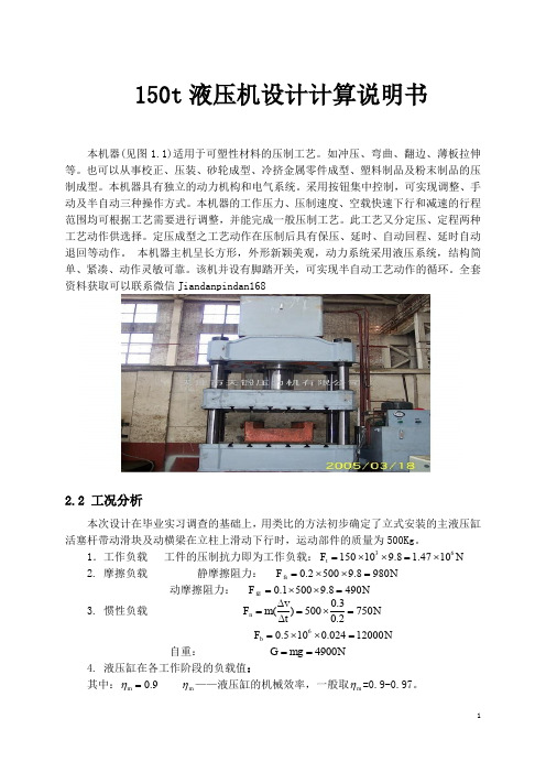
150t 液压机设计计算说明书本机器(见图1.1)适用于可塑性材料的压制工艺。
如冲压、弯曲、翻边、薄板拉伸等。
也可以从事校正、压装、砂轮成型、冷挤金属零件成型、塑料制品及粉末制品的压制成型。
本机器具有独立的动力机构和电气系统。
采用按钮集中控制,可实现调整、手动及半自动三种操作方式。
本机器的工作压力、压制速度、空载快速下行和减速的行程范围均可根据工艺需要进行调整,并能完成一般压制工艺。
此工艺又分定压、定程两种工艺动作供选择。
定压成型之工艺动作在压制后具有保压、延时、自动回程、延时自动退回等动作。
本机器主机呈长方形,外形新颖美观,动力系统采用液压系统,结构简单、紧凑、动作灵敏可靠。
该机并设有脚踏开关,可实现半自动工艺动作的循环。
全套资料获取可以联系微信Jiandanpindan1682.2 工况分析本次设计在毕业实习调查的基础上,用类比的方法初步确定了立式安装的主液压缸活塞杆带动滑块及动横梁在立柱上滑动下行时,运动部件的质量为500Kg 。
1.工作负载 工件的压制抗力即为工作负载:36150109.8 1.4710t F N =⨯⨯=⨯ 2. 摩擦负载 静摩擦阻力: 0.25009.8980fs F N =⨯⨯=动摩擦阻力: 0.15009.8490fd F N =⨯⨯=3. 惯性负载 0.3()5007500.2n v F m N t ∆==⨯=∆60.5100.02412000b F N =⨯⨯= 自重: 4900G mg N == 4. 液压缸在各工作阶段的负载值:其中:0.9m η= m η——液压缸的机械效率,一般取m η=0.9-0.97。
2.3负载图和速度图的绘制:负载图按上面的数值绘制,速度图按给定条件绘制,如图:三液压机液压系统原理图设计3.1 自动补油的保压回路设计考虑到设计要求,保压时间要达到5s,压力稳定性好。
若采用液压单向阀回路保压时间长,压力稳定性高,设计中利用换向阀中位机能保压,设计了自动补油回路,且保压时间由电气元件时间继电器控制,在0-20min内可调整。
压块机操作规程
压块机操作规程压块机操作规程一、压块机的基本操作规范1. 操作前的准备工作(1)确认压块机的工作状态正常,并进行必要的维护和保养。
(2)检查压块机的压力调节装置是否正确设定,确保在操作过程中能够保证合适的压力。
(3)清除压块机工作区域周围的杂物,确保操作时的安全和顺畅。
(4)按照工作需求,准备好需要压制的原材料,并放置在储料斗内。
2. 操作时的安全规范(1)操作人员必须穿戴好安全防护装备,包括工作服、手套、安全帽等。
(2)操作人员要保持机器和工作区域的清洁,防止滑倒和其他安全事故。
(3)操作过程中,切勿将手或其他身体部位伸入机器内部,以免发生危险。
3. 压块机的操作流程(1)启动压块机,待机器正常运行后,将原材料放入储料斗内。
(2)调整压力调节装置,使之适应所需压块的要求。
(3)开始压制过程,将原材料逐渐送入压块机,保持均匀的供料速度。
(4)当压块机完成一次压制后,立即停止供料,并等待压块机将压制好的块体排出。
(5)清除剩余原材料,以便进行下一次压制。
二、压块机的维护保养规范1. 定期检查和清洁压块机的各个零部件,确保其正常运行。
2. 定期清理和更换润滑油,以保证润滑系统的畅通和零部件的正常工作。
3. 对压块机的传动装置进行定期检查和维护,确保其工作平稳可靠。
4. 定期检查和更换磨损的零部件,以保证压块机的压力和压制效果。
5. 减少机器的过载使用,以延长其使用寿命并避免机器的损坏。
三、压块机的故障排除规范1. 压块机无法启动(1)检查电源是否正常连接,并确认没有电源问题。
(2)检查保险丝是否损坏,并确认替换合适的保险丝。
(3)检查控制开关是否正常,如需更换,应立即更换。
2. 压块机压力不足或过大(1)检查压力调节装置是否正确设定,并根据需要进行调整。
(2)检查液压系统是否正常工作,如需要,及时维修或更换液压元件。
3. 压块机压制效果不佳(1)检查原材料的水分含量是否适中,确保其能够达到最佳压制效果。
150型全液压钻机操作规程[1]
![150型全液压钻机操作规程[1]](https://img.taocdn.com/s3/m/8c720d838762caaedc33d405.png)
150型全液压钻机操作规程一、开机前的准备工作:1、检查各油管连接是否正确;2、检查各连接螺栓是否拧紧,立柱是否锚牢固;3、点动电动机,检查电动机的旋向与齿轮泵壳体上的标定转向是否一致;4、检查操纵三路阀手把,使其处于中位(0位)。
二、钻进时的操作:1、钻机空运转1分钟,检查钻机各部件运转是否正常;2、操纵卡盘手把,使卡盘夹紧水辫轴锥螺纹或钻杆,开启冷却水;3、操纵旋转手把至正转位,使动力头带动钻杆正转;4、操纵前进、后退手把至前进位,使给进油缸以正常速度钻进;5、在钻进过程中,因切削阻力发生变化时,可调节节流阀来控制推进速度。
节流阀反时针旋转,推进速度加快;顺时针旋转推进速度减慢。
三、加接钻杆时的操作:1、钻进完成1根钻杆深度需加接钻杆时,先停止推进,再停止旋转;2、操纵夹持手把,使夹持器夹紧钻杆,将节流阀开启(右旋)至最小位置;3、后退给进油缸,操作手把处于浮动位置,使水辫轴与钻杆旋离;4、停止旋转,操纵快速进退手把至快退位置,使动力头快速退到位;5、将要加接的钻杆接在前一根钻杆上,回转器边旋边前进,当水辫轴梯形锥螺纹与新加接钻杆锥螺纹旋合接触时,松开夹持器,完成钻杆加接。
四、卸钻杆的操作:1、夹持器夹紧水辫前的第一根钻杆,操作手把向后拉,手把置于后退浮动位置,使水辫轴与第一根钻杆分离;2、卸下第一根钻杆,再按上一条操作,如此循环反复,直到卸完全部钻杆。
五、操作中的注意事项:1、孔内有钻具时,除按规定程序的动作需要外,不允许回转器反转;2、回转器反转拆卸钻杆时,油缸必须留足卸扣行程,以免损坏钻杆螺纹;3、钻机工作过程中,应随时注意各运动部件的温度变化。
轴承、齿轮、油泵、油马达、电动机等处的温升不得超过45℃,油箱出油口处的温度不得超过50℃,否则应停机检查并加以处理;4、观察泵站回油压力表,发现回油压力超过0.6Pa时应停机更换或清洗过滤器;5、钻机工作时,注意液压系统的元件,胶管及管接头是否有漏油现象;各机械连接部件、锚固部件是否有松动现象,如有故障应及时处理;6、钻机工作时,除了因钻进负荷变化而引起的供油压力,旋转和推进速度的相应变化,系统压力突然大幅度升降引起旋转、推进速度巨变,应立即停机,找出原因,处理故障;7、当钻机停止工作时,所有操作手把应置于中位。
压机使用说明书(范本)

压机使用说明书压机使用说明书篇一:KD3800压机操作说明书 KD3800全自动液压压砖机使用说明书(机械部分) 广东科达机电股份有限公司二零零一年五月目录一、总则二、机械概述三、安全说明四、安装过程五、操作规程六、维护与保养七.压制砖坯规格表八、用户自购备件明细表九.随机附件明细表附图一、压机外形图附图二、压机主体附图三、液压部阀组结构图附图五、复合顶出装置结构图附图六、模具安装连接尺寸图(一、二) 附图七、液压气动原理图附图八、压制曲线图附图九、地基图附图十、压机吊装图附图十一、冲头开关箱附图十二、锁模安装示意图附图十三、复合顶出系统装模示意图一.总则1.在压机使用之前,操作人员及日常维护人员需经过培训及仔细阅读说明书的全部内容,这样对操作人员、维修人员及设备自身的安全很重要。
本手册中所述的产品及材料会因技术原因或工作原因随时更改,我们保留更改的权利,恕不另行通知。
说明书的内容属于有价技术资料,不得交付第三方复印或转让。
2.严格按本说明书操作、维护压机,未按本说明书操作、维护产生的不良后果本公司不负责任。
3.用户对说明书必须妥善保管,为便于查阅,说明书应放在靠近设备的地方,使操作和维修人员能在需要的时候及时查阅。
4.对工作循环和机器结构进行的任何修改请向科达集团的产品支持人员咨询,只有他们才有权进行这项工作。
5.压机的使用寿命为10年,本手册也应妥善保管10年以上。
对使用非原装配件导致的设备损坏本公司不承担责任。
6.压机铭牌公称压制力(t)二.机械概述1.设备概述 KD3800全自动液压压砖机(以下简称科达系列压机)是全自动化设备,专门用于陶瓷墙地砖生产过程中的粉料压制成型。
它由主机部分、液压部分和电气控制部分组成,本机采用液压传动,用可编程控制器实现控制功能。
DCY150液压平板车使用说明书(部分)适用于大方系列平板车
DCY150型动力平板运输车使用说明书郑州大方桥梁机械有限公司苏州分公司前言DCY150型动力平板运输车专为造船厂设计制造,额定装载质量为150吨。
本说明书简要介绍了DCY150型动力平板运输车的各项技术参数、性能指标及使用保养注意事项,希望用户严格按照本说明书的要求使用、保养车辆。
由于各方面的发展和改进,日后若有同型产品的更改,恕不另行通知。
我公司欢迎用户对产品提出改进意见和建议。
郑州大方桥梁机械有限公司苏州分公司2006.6目录第一章概述 (7)第二章主要工作原理 (12)第三章主要结构 (14)第四章微电控制系统 (20)第五章操作与使用 (28)第六章维护时间表 (41)附件1.康明斯C300 20水冷柴油机使用说明书2.图1 总图3.图2 转向模式示意图4.图3 仪表板布置示意图5.图4 液压系统原理图6.图5 空气制动系统原理图7.图6 发动机控制原理图8.图7 A驾驶室电气原理图9.图8 B驾驶室电气原理图10.图9.1 A驾驶室微电控制系统原理图11.图9.2 B驾驶室微电控制系统原理图12.图9.3 传感器安装分布图13.图9.4 开关量输入接线图14.图10 重心放置示意图15.图11 载荷放置示意图16.图12 润滑部位示意图17.A4VG 电控变量泵样本 REXROTH液压公司18.A11VO 电控变量泵样本 REXROTH液压公司19.A6VE28 油马达样本 REXROTH液压公司20.液压冷却器样本 AKG液压公司21.PSV电控比例多路换向阀样本 HAWE液压公司特别注意1.微电系统在行车安全方面的设计·偏载报警偏载10 %报警;·超载报警按最大装载质量150 000kg执行;2.车辆在行走时,禁止搬动“行驶方向”选择开关;只有在停车时,方可改换行走方向;3.车辆在行走时,严禁“平升平降”操作;4.重载时爬坡,请选择“爬坡”档;5.禁止在坡道上进行“原地回转”操作;6.避免在重载工况下调整车辆,调整车辆应在空载和停车状态下进行。
CaddyTig150 CaddyTig200中文
CaddyTig 150 CaddyTig 200操作说明书(中文译本)目录1 指示 (3)2 安全 (3)3 简介 (5)3.1 配置 (5)4 技术参数 (5)4.1 设置 (6)5 安装 (7)5.1 放置 (7)5.2 铭牌 (7)5.3 主电源 (7)5.4 接口与控制设备 (8)6 维护 (8)6.1 控制面板 (8)6.2 过热保护 (9)6.3 隐藏功能 (9)7 焊接 (10)7.1 TIG焊接 (10)7.2 MMA焊接 (13)8 焊接数据存储器 (14)9 维护 (14)9.1 清洁虑网 (14)10 故障诊断 (15)10.1 故障代码 (15)11 配件订购 (16)电路图 (17)分类号 (21)配件清单 (22)附件 (23)1指示授权声明ESAB焊接设备AB,695 81 Laxå, Sweden 对按照IEC/EN60974-1和EN50199标准生产,出厂编号为316/402起的CaddyTig 150/CaddyTig 200焊接电源满足73/23/EEA,89/336/EEC指令以及93/68/EEC附录要求,提供无保留保证。
______________________________________________________________________________________________ Laxå 2001-04-18Joakim CahlinVice PresidentESAB Welding Equipment AB695 81 LAXÅSWEDEN Tel:+46 584 81000 Fax:+46 584 4119242安全ESAB焊接设备用户的根本职责是保证设备附近工作或旁观的任何人能观察到相应的安全警告。
安全预防必须满足这种类型焊接设备的要求。
除了工作场所的标准规则之外,下列劝告事宜亦应遵守。
Arcan 100 150 吨空气液压车间压机操作手册说明书
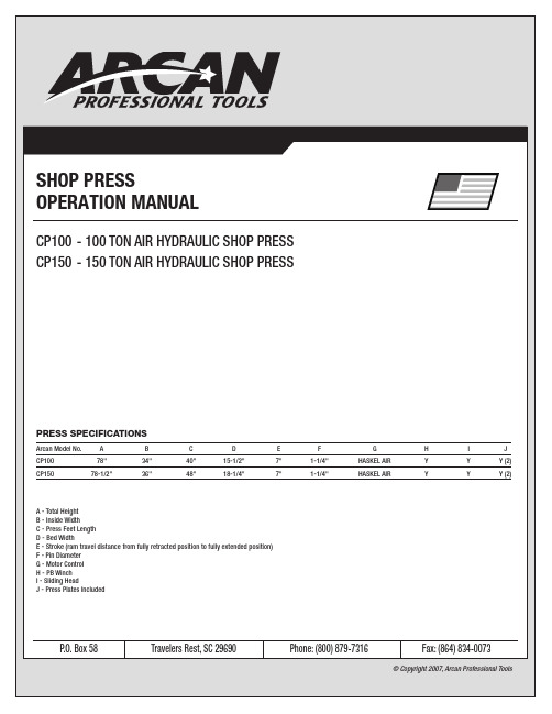
SHOP PRESSOPERATION MANUALCP100 - 100 TON AIR HYDRAULIC SHOP PRESS CP150 - 150 TON AIR HYDRAULIC SHOP PRESSP .O. Box 58 Travelers Rest, SC 29690 Phone: (800) 879-7316 Fax: (864) 834-0073Arcan Model No. ABCDEFGHIJCP10078" 34" 40" 15-1/2" 7" 1-1/4" HASKEL AIR Y Y Y (2)CP150 78-1/2" 36" 48" 18-1/4" 7" 1-1/4" HASKEL AIR Y Y Y (2)A - Total HeightB - Inside WidthC - Press Feet LengthD - Bed WidthE - Stroke (ram travel distance from fully retracted position to fully extended position)F - Pin DiameterG - Motor ControlH - PB WinchI - Sliding HeadJ - Press Plates IncludedPRESS SPECIFICATIONS© Copyright 2007, Arcan Professional ToolsSAFETY INFORMATIONThis symbol alerts you to the possibilityof serious injury or death if instructionsare not followed.This symbol alerts you to the possibilityof damage to or destruction of equipmentif instructions are not followed.Failure to heed these warnings may result in lossof load, damage to the press and/or failureresulting in property damage, personal or fatal injury. This operating manual contains important details concerning the safe operation of this tool. The user must read and understand these details before any use of the tool. This manual must be retained for future reference.• Read, study, and understand all instruction manuals packed with this press before operating.• Always wear safety goggles.• Parts being pressed may splinter, shatter, or be ejected from the press at a dangerous rate of speed. Because of the variety of pressapplications, it is your responsibility to always use adequate guardsand wear eye protection and heavy protective clothing when operatingthepress.• Visual inspection should be made before each use of the press, checking for signs of cracked welds, bent bed pins, loose or missing bolts, leaks, or any other structural damage.• Do not go near leaks. High pressure oil can puncture skin and cause serious injury, gangrene, or death. If injured, seek emergency medical help. Immediate surgery is required to remove oil.• Keep hands and fingers out of the press and away from parts that may shift and pinch. Do not stand in front of work area when load is applied. • Always use an accurate pressure gauge to measure pressing force.• Do not exceed the rated capacity of this press.• Never tamper with hydraulic system pressure settings.• Do not substitute bolts, pins or any part of the components. Use only genuine factory replacement parts.• Always center load on ram plunger. Offset loads can damage ram and may cause load to eject at a dangerous rate of speed.• Remove all loads from press bed before attempting to adjust bed height.Beware of possibility of falling bed.• Press only on loads supported by press bed and included press plates.Do not support loads on floor or press frame.• When using any accessories such as arbor plates, be certain they are centered on press bed and are in full contact with press bed.• Before applying load, be certain all press bed supporting pins are fullyengaged.• Always use a bearing shield when pressing bearings. Use caution when positioning work to be pressed to ensure that the item that is to bepressed cannot be dislodged or broken during press work. This mayresult in the item being ejected from the press at a dangerous rate ofspeed.• Release hydraulic pressure before loosening any fittings.• Maintain proper hydraulic fluid levels.• Do not make any alterations to the press.OWNER/USER RESPONSIBILITYThe owner and/or user must have an understanding of the manufacturer's operating instructions and warnings before using this press. Personnel involved in the use and operation of equipment must be careful, competent, trained, and qualified in the safe operation of the equipment and its proper use when servicing motor vehicles and their components.Warning information should be emphasized and understood.If the operator is not fluent in English, the manufacturer's instructions and warnings must be read to and discussed with the operator in the operator's native language by the purchaser/owner, making sure thatthe operator comprehends its contents.Owner and/or user must study and maintain for future reference the manufacturer’s instructions. Owner and/or user is responsible for keeping all warning labels and instruction manuals legible and intact. Replacement labels and literature are available from the manufacturers.INSPECTIONVisual inspection of the shop press should be made before each use of the press, checking for damaged, loose or missing parts. Each press must be inspected by a manufacturer’s repair facility immediately if subjected to an abnormal load or shock. Any press which appears to be damaged in any way, is found to be badly worn, or operates abnormally must be removed from service until necessary repairs are made by a manufacturers's authorized repair facility. It is recommended that an annual inspection of the press be made by a manufacturer’s authorized repair facility and that any defective parts, decals or warning labels be replaced with manufacturer’s specified parts. A list of authorized repair facilities is available from the manufacturer. SAFETY INSTRUCTIONS• CHECK YOUR LOCAL, STATE AND FEDERAL REGULATIONS REGARDING THE SAFE USE OF THIS EQUIPMENT.• Your safety is a top priority. Please handle equipment with care.• Fully retract unit and remove all items from the press bed frame.• Support the press bed and remove the pins.• Raise or lower bed to desired height and reinstall press pins. Be certain pins are fully engaged in the parallel flanges of the upright columns.• Position press on a flat, level, hard surface, preferably concrete.Make sure all nuts and bolts are tight.• Clear the area of bystanders, especially small children, before using.• Set the press bed to the required height. The press is most effective when the work piece is located 1 inch below the ram’s retracted position.The compression stroke can include the entire 5 inch working range.• The press is designed to exert a force on anything which is positioned beneath its ram. The work piece can be ejected from under the ram ata high rate of speed and can injure someone.• Pressing Bearings: It is essential that you use the bearing shield when pressing bearings are on or off.OPERATION1. Press beds are adjustable up and down to fully take advantageof available ram travel and numerous work pieces.2. Slowly open release valve on power unit. With the power unitin its stored position, remove all items from the press bed.3. Be sure press bed is supported properly and remove press bed pins.4. Raise or lower press bed to desired height, and reinstall pressbed pins. Be certain pins are completely through both sidesof frame, as these pins are the major support mechanism for the bed.We want to know if you have any problems with our products.If you are missing any parts or find any damage, call Arcan directly,and we will remedy the situation. Please do not call the store whereyou purchased this product.Phone: (800) 879-7316Email:**********************AIR SUPPL Y160-180PSI recommended for best operation.FLUID LEVELSUse AW-32 hydraulic oil ONL Y and fill to level indicated on tank (just below fill plug).WATER FIL TEREmpty water and replace filter as recommended in manufacturer’s instructions.Excess moisture in air supply can shorten air motor life and cause erratic operation.SLIDING HEADRam can be moved from left to right.Do not attempt to move ram while press is in operation.OPERATING INSTRUCTIONSRemove all items from press bed before operating winch.Do not operate press without all press bed pins in place. The winch and winch cable are designed to support the weight of the press bed only. Using the press without the pins in place can result in damage to the press, personal injury or death.TO RAISE OR LOWER PRESS BED• Once press bed has been positioned and all pins are in place, release tension on cable so press bed is supported entirely by the press pins.• Move winch handle toward back of press to lower bed.• Move winch handle toward front of press to raise bed.TO RETRACT RAM1. Open release valve by turning counter-clockwise.2. Move control valve handle to extreme right.TO LOWER RAM1. Move control valve handle to the left.TO CONTROL RAM SPEED• Open release valve for faster ram speed.• Close release valve when ram contacts work surface.• Ram will not apply pressure until release valve is closed.Keep air control valve handle in center position when press is not in use.Do not leave air supply connected when press is not in use. Pressure will force oil into air lines and air motor.Do not overextend ram. This device is equipped with a safety release valve; however, overextending the ram can result in damage to equipment, personal injury or death.CAUTIONCAUTIONCAUTION WARNINGWARNINGCAUTION SPECIFICATIONS & OPERATING INSTRUCTIONSNOTESNote:- RETAIN THIS MANUAL FOR FUTURE REFERENCE.- RETAIN AIR MOTOR AND WINCH MANUALS FOR FUTURE REFERENCE.- REFER TO AIR MOTOR MANUAL FOR MAINTENANCE INSTRUCTIONS.FRONT VIEWPARTS DIAGRAM SLIDING HEAD RAM EXTENSION LINEAIR MOTOR (#2)RAM RETURN LINE AIR EXHAUST VALVESRELEASE VALVEWINCH (#4)FLUID LEVELSPRESS PIN (#1)PRESS PIN (#1)(150 TON ONLY)PRESS PIN (#1)BYPASS LINEWATER FILTER RELEASE VALVEAIR SUPPLYAIR CONTROL VALVE (#3)RELEASE VALVEPRESS PLATES (#5)SIDE VIEWBACK VIEWITEM NO. ARCAN PART NO. DESCRIPTION QTY.1RSCBP1225 Press Pin (100 Ton Press) 4RSCBP1225 Press Pin (150 Ton Press)62 RS150AM Air Motor 13 RS150CV Rexroth Control Valve 14 RS150W Winch (only) 15 RS150PP Press Plate 26 RS310012 Pushing Adapter 17 RSBS1 Bearing Shield1PUSHING ADAPTER (#6)BEARING SHIELD (#7)。
最新150T及250T压铸机安全操作规程汇总

制定:
审核
批准日期
备注
修改:
审核
批准日期
灯会亮,并会显示出异常码。
5.9按下油泵马达开关。确认油泵是否有杂音产生,如果有,请按急停,再按启动,如
此断续运转3~4回后,没有杂音时,再行连续运转。
5.10急停开关测试。看急停开关按下后,马达是否停止运转。
5.11按5.9项的操作,再将油泵启动一次。
5.12按《点检卡》要求检查机械的每一部分。
5.13检查溶解炉温度及铝锭熔化情况,并把坩埚内之氧化物去处。确认温度必须保持
150T及250T压铸机安全操作规程
WI306-001
150T,250T及800T压铸机安全操作规程
更改序号:0
制定日期99/7/8ቤተ መጻሕፍቲ ባይዱ
最新更改日期
页码1of1
文件号:9907001
1.当操作时,操作者身体任何一部分,均不能置于活动之机构内。
2.当机械操作时,一定要使用安全装置,而且该安全装置须置于正确位置上。
3.安全装置决不能擅自去修改它。
4.未操作前,操作者必须要确实的知道安全装置及急停按钮的正确位置,并做操作前的测试。
5.操作前注意事项:
5.1检查及清洗模具:模穴,料管,柱塞头。确认定位销,斜销,顶出销,抽芯滑道是
否损伤,及润滑油是否适当。
5.2预热模具穴面。确认表面加热至200C。
5.3打开压缩空气开关。确认减压阀上之压力计是否在5kgf/cm2以上。
5.4打开冷却水的开关。确认液压油冷却器,模具冷却管,柱塞头冷却管是否有适当之
水量及漏水情况。
5.5确认润滑油的油量是否足够。查看油量计,如有不足再行补充。
黑鹰自动汽车黑鹰BH2015-M0 11 07 1.5吨汽缸长搬运机操作说明书
ModelCapacity BH2015 1 1/2 Ton3 Ton4 Ton 8 Ton8 TonSFA Companies10939 N. Pomona Ave. Kansas City, MO 64153******************************Hydraulic Long RamsOperating Instructions & Parts ManualSAFETY and GENERAL INFORMATIONSave these instructions.For your safety read, understand, and follow the information provided with and on this ram. The owner and operator of this equipment shall have an understanding of this ram and safe operating procedures before attempting to use. The owner and operator shall be aware that use and repair of this product may require special skills and knowledge. Instructions and safety information shall be conveyed in the operator's native language before use of this ram is authorized. If any doubt exists as to the safe and proper use of this ram, remove from service immediately.Inspect before each use.Do not use if broken, bent, cracked, or damaged parts (including labels) are noted. Any ram that appears damaged in any way, operates abnormally or is missing parts, shall be removed from service immediately and the manufacturer notified. If you suspect that the ram was subjected to a shock load (a load dropped suddenly, unexpectedly upon it), immediately discontinue use until the ram has been checked by a factory authorized service center (contact distributor or manufacturer for list of Authorized Service Centers). It is recommended that an annual inspection be done by qualified personnel. Replace worn or damaged parts with Blackhawk authorized replacement parts only. Labels and owner’s manuals are available from manufacturer.PRODUCT DESCRIPTIONHydraulic long ram is designed to lift, not support, rated capacity loads. This ram is intended to be used with corresponding Blackhawk Automotive engine cranes. Immediately after lifting, the load must be supported by mechanical means. For air option model, ensure that air source can dedicate 7.8 CFM @ 110-175 psi to each ram operated.Never use hydraulic ram as a stand alone device. After lifting, immediately support the lifted loadwith appropriately rated mechanical support.PREPARATIONBefore Use1. Verify that the product and application are compatible, if in doubt contact customer support (816) 891-6390.2. Before using this product, read the operator's manual completely and familiarize yourself thoroughly with theproduct, its components and recognize the hazards associated with its use.3. To familiarize yourself with basic operation, locate and turn the release valve lever:a. Clockwise until firm resistance is felt to further turning. This is the ‘CLOSED’ release valve position used toraise the ram plunger.b. Counter-clockwise, but no more than 1/2 turn from the closed position. This is the ‘OPEN’ release valveposition used to lower the ram plunger.4. With ram plunger fully retracted, locate and remove the oil filler plug. Insert the handle into the handle sleeve,then pump 6 to 8 strokes. This will help release any pressurized air, which may be trapped within the reservoir.Ensure the oil level is just below the oil filler hole. Reinstall the oil filler plug.5. For air option model BH2081:Pour a teaspoon of good quality, air tool lubricant into the air supply inlet of the lift control valve. Connect to air supply and operate for 3 seconds to evenly distribute lubricant.Note: The ram is equipped with the popular 1/4" NPT air coupler. When installing a different air coupler of your choice, ensure that thread tape or compound is used when servicing connections. To ensure dependable, trouble free operation an inline air dryer and oiler is recommended.6. Check that the pump operates smoothly before putting into service. Replace worn or damaged parts and assemblieswith Blackhawk authorized replacement parts only.Bleeding / Venting Trapped AirWith the release valve in the OPEN position (3b above) and with ram plunger fully lowered, locate and remove the oil filler plug. Insert the handle into the handle sleeve; then pump 6 to 8 full strokes. This will help release any pressurized air which may be trapped within the reservoir. Oil level should be even with the bottom of the oil filler hole. Reinstall the oil filler plug.SPECIFICATIONSOPERATIONRaising the Ram Plunger1. Locate and close release valve by turning it clockwise until firm resistance is felt to further thread engagement.2. To raise:a) For models BH2015, BH2035, BH2045 & BH2085: Insert handle into handle sleeve and pump.b) For model BH2081: Squeeze the lift control valve or insert handle into handle sleeve and pump.DO NOT OPERATE BY AIR AND BY HAND PUMPING AT THE SAME TIME.3. Continue pumping until load reaches desired height.4. Immediately secure lifted load with appropriately rated mechanical means such as jack stands or engine stand.LoweringMake certain that all personnel are clear of the load before lowering. Control the rate of descent of the at all times. The more you open the release valve, the faster the load descends.1. Raise load high enough to clear the mechanical supports, then carefully remove the supports.2. Slowly turn the release valve lever counter-clockwise, but no more than 2 turns. If the load fails to lower:a. Use another lifting device or ram to raise the load high enough to reinstall mechanical supports.b. Remove the affected ram and then the supports.c. Lower the load by turning the release valve lever counter-clockwise, but no more than 2 turns.3. After removing ram from under the load, push ram plunger and handle sleeve down to reduce exposure to rustand contamination.MAINTENANCEImportant : Use only a good grade hydraulic oil. Avoid mixing different types of fluid and NEVER use brake fluid, turbine oil, transmission fluid, motor oil or glycerin. Improper fluid can cause premature failure of the ram and the potential for sudden and immediate loss of load. We recommend Hein-Werner HW93291 or equivalent.Adding oil1. With ram plunger fully lowered and pump piston fully depressed, set ram in its upright, level position. Remove oil filler plug.2. Fill with oil until just below the rim of the oil filler hole. Reinstall the oil filler plug. Changing oilFor best performance and longest life, replace the complete fluid supply at least once per year.1. With ram plunger fully lowered and pump piston fully depressed, remove the oil filler plug.2. Lay the ram on its side and drain the fluid into a suitable container.Note: Dispose of hydraulic oil in accordance with local regulations.3. Fill with oil until just below the rim of the oil filler hole. Reinstall the oil filler plug.Lubrication1. A periodic coating of light lubricating oil to pivot points, axles and hinges will help to prevent rust and assure that pump assemblies move freely.2. For air option model BH2081: When used on a daily basis, air pump should be internally lubricated before each use. Use only good quality air tool lubricant. If no inline oiler is used, pour a teaspoon of air tool oil into the inlet of the air control valve. Simply operate the ram using the air feature in order to fully distribute the oil.CleaningPeriodically check the pump piston and ram plunger for signs of rust or corrosion. Clean as needed and wipe with an oily cloth.Note: Never use sandpaper or abrasive material on these surfaces!StorageWhen not in use, store the ram with pump piston and ram plunger fully retracted and air supply disconnected.5TROUBLESHOOTINGSymptomPossible CausesCorrective ActionRam will not lift load• Release valve not tightly closed • Load is too heavy• Ensure release valve tightly closed • Consider higher capacity ram Ram will lift, but not maintain pressure• Release valve not tightly closed • Hydraulic unit malfunction • Ensure release valve tightly closed • Contact Blackhawk Tech. Service Ram will not lower after unloading• Reservoir overfilled • Ensure load is removed, then drain fluid to proper levelPoor lift performance• Fluid level low• Air trapped in system• Ensure proper fluid level• With ram fully retracted, remove oil filler plug to let pressurized air escape, then reinstall oil filler plug Will not lift to full extension • Fluid level low• Ensure proper fluid levelREPLACEMENT PARTSNot all components of the ram are replacement items, but are illustrated as a convenient reference of location andITEM Parts Number for Model DESCRIPTION QTY BH2015BH2035BH2045BH2085BH208115905-00100-100Filler Plug1 25905-00056-000Seal1 3BL80-16001-000Release Valve1 4BL80-16002-000Release Lever1 55107-05016-000Screw1 6G931-07015-000 Filter2 7BL80-15000-000(2 pc. for model BH2081)Hydraulic Cartridge1 8BL80-14002-000Washer1 9BL80-14001-000Pump Cylinder1 10BL80-14101-000Pump Piston1 115403-08028-000Pin2 12BL80-13000-000Handle Sleeve1 135405-02018-000Snap Pin2 14BL80-20000-000BL80-42000-000Handle1 15N/A A27010-0001Air Motor1 16N/A A270-01100-0000Piston, Air Motor1 17N/A A27010-0002Air Inlet Swivel1 18N/A A20060-0005Hose Assembly1 19N/A A20060-0006Air Hose1 20N/A A20060-0007Air Control Valve1 21BL400S-034BL800S-034Seal Kit (#1, 2 & A~J)1 22N/A N/A A27010-0000Seal Kit for Air Motor# 151Seal Kit (item#21) Contents:Item Description Qty1Filler Plug12Seal1A O-ring1B O-ring1C Gasket1D Back-up Ring1E U-cup1F Back-up Ring1G Seal1H Seal1I O-ring1J Seal1ONE YEAR LIMITED WARRANTYFor a period of one (1) year from date of purchase, SFA Companies will repair or replace, at its option, without charge, any of its products which fails due to a defect in material or workmanship under normal usage. This limited warranty is a consumer’s exclusive remedy.Performance of any obligation under this warranty may be obtained by returning the warranted product, freight prepaid, to SFA Companies Warranty Service Department, 10939 N. Pomona Ave., Kansas city, MO 64153. Except where such limitations and exclusions are specifically prohibited by applicable law.(1) THE CONSUMER’S SOLE AND EXCLUSIVE REMEDY SHALL BE THE REPAIR OR REPLACEMENT OF DEFECTIVE PRODUCTS AS DESCRIBED ABOVE.(2) SFA COMPANIES SHALL NOT BE LIABLE FOR ANY CONSEQUENTIAL OR INCIDENTAL DAMAGE OR LOSS WHATSOEVER.(3) ANY IMPLIED WARRANTIES, INCLUDING WITHOUT LIMITATION THE IMPLIED WARRANTIES OF MERCHANTABILITY AND FITNESS FOR A PARTICULAR PURPOSE, SHALL BE LIMITED TO ONE YEAR, OTHERWISE THE REPAIR, REPLACEMENT OR REFUND AS PROVIDED UNDER THIS EXPRESS LIMITED WARRANTY IS THE EXCLUSIVE REMEDY OF THE CONSUMER, AND IS PROVIDED IN LIEU OF ALL OTHER WARRANTIES, EXPRESS OR IMPLIED.(4) ANY MODIFICATION, ALTERATION, ABUSE, UNAUTHORIZED SERVICE OR ORNAMENTAL DESIGN VOIDS THIS WARRANTY AND IS NOT COVERED BY THIS WARRANTY.Some states do not allow limitations on how long an implied warranty lasts, so the above limitation may not apply to you. Some states do not allow the exclusion or limitation of incidental or consequential damages, so the above limitation or exclusion may not apply to you. This warranty gives you specific legal rights, and you may also have other rights which vary from state to state.SFA Companies10939 N. Pomona Ave. Kansas City, MO 64153816-891-6390******************************。
无锡锅炉150吨高温高压循环流化床锅炉说明书要点
目录一、前言 (2)二、锅炉基本特性 (2)1.主要工作参数 (2)2.设计燃料 (3)3.安装和运行条件 (4)4.锅炉基本尺寸 (4)三、锅炉结构简述 (4)1.炉膛水冷壁 (5)2.高效蜗壳式汽冷旋风分离器 (6)3.锅筒及锅筒内部设备 (7)4.燃烧设备 (8)5.过热器系统及其调温装置 (10)6. 省煤器 (11)7. 空气预热器 (11)8. 锅炉范围内管道 (12)9. 吹灰装置 (12)10. 密封装置 (12)11. 炉墙 (12)12. 构架 (13)13.膨胀系统 (14)14.锅炉水压试验 (14)15. 锅炉过程监控 (14)四、性能说明 (16)一、前言我国电站锅炉的燃料主要以化石燃料为主;锅炉燃烧化石燃料所产生的烟气,携带有SO2、NOx、粉尘等有害物质,是我国许多城市雾霾产生的因素之一,为此2012年国家颁布了火电厂大气污染物排放标准GB13223-2011,要求新建锅炉烟气有害气体排放中SO2<100 mg/m3、NO x<100 mg/m3;2014年已在全国主要省区逐步推广,并推广到全国。
2015年国家又颁布了环保法,以法律的形式,要求产生污染源的企业,污染排放必须符合国家有关排放规定,为此我们无锡华光锅炉股份有限公司,紧跟市场的需求,按照全新的低氮燃烧、低能耗设计理念,设计制造出低排放、低能耗、高可靠性的新型环保循环流化床锅炉,来满足用户最新的要求。
由于脱硫剂加大了NOx原始排放量,因此我们希望在锅炉尾部采用烟气脱硫的工艺进行脱硫;我们在返料腿上设置了脱硫剂加入口,作为炉内临时石灰石脱硫之用。
二、锅炉基本特性1、主要工作参数额定蒸发量 150 t/h额定蒸汽温度 540 ℃额定蒸汽压力(表压) 9.8 MPa给水温度 215 ℃锅炉排烟温度~137 ℃排污率≤1 %空气预热器进风温度 30 ℃锅炉计算热效率 91.5 %锅炉保证热效率 91 %燃料消耗量 24.3 t/h(设计煤种)一次热风温度 175 ℃二次热风温度181 ℃一、二次风量比 50:50循环倍率 20 ~ 25灰渣比 7:32、设计燃料(1)煤质分析资料:入炉给煤粒度:煤的入炉粒度要求:粒度范围0~10mm,50%切割粒径d50=2mm。
150吨电动胎压机操作手册说明书
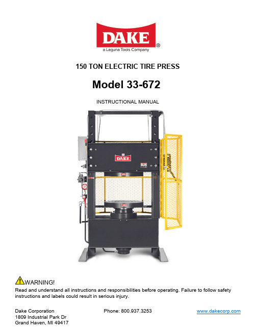
150 TON ELECTRIC TIRE PRESSModel 33-672INSTRUCTIONAL MANUALWARNING!Read and understand all instructions and responsibilities before operating. Failure to follow safety instructions and labels could result in serious injury.Dake Corporation Phone: 800.937.3253 TABLE OF CONTENTSSAFEGUARDING THE POINT OF OPERATION (2)SPECIFICATIONS (3)SAFETY (4)SET UP (5)OPERATION (5)MAINTENANCE (6)LUBRICATION (6)REPLACING HYDRAULIC OIL (6)TROUBLESHOOTING (6)ELECTRICAL DIAGRAM (8)HYDRAULIC DIAGRAM (9)EXPLODED VIEWS & PARTS LISTS (10)ORDERING INFORMATION (16)SAFEGUARDING THE POINT OF OPERATIONANSI B11.2 - Hydraulic Power Presses -Safety Requirements for Construction, Care, and UseIt is important that Dake press users have a clear understanding of their responsibility involving the care and use of their Dake hydraulic press, including point-of-operation safe guards. Dake strongly recommends that Dake press users obtain a copy of the current American National Standard Institute (ANSI) B11.2 standard, for a more complete understanding of their responsibilities.ANSI B11.2 states the following, relative to point of operation safeguarding:“Normally, only the employer (press user) can determine the requirements of the press productions system components, including the dies and methods for feeding. Therefore, the employer is ultimately responsible to designate and provide the point-of-operation safeguarding system.”The standard also discusses additional responsibilities of the employer. Some of the key responsibilities are: •The employer is responsible for the safety, use, and care of the hydraulic power press production system. •The employer is responsible to consider the sources of hazards for all tasks to be implemented on the hydraulic power press production system.•The employer is required to eliminate or control identified hazards in the scope of their work activity. •The employer is responsible for the training of personnel, caring for, inspecting, maintaining, and operating hydraulic press production systems to ensure their competence.•The employer is responsible to provide and ensure that point-of-operation safeguarding is used, checked, maintained, and where applicable, adjusted on every production operation performed on a pressproduction system.A complete and current copy of the ANSI B.11.2 standard can be obtained by contacting the following:American National Standards Institute1430 BroadwayNew York, NY 10018AMT – The Association For Manufacturing Technology7901 Westpark DriveMcLean, VA 22102SPECIFICATIONSModel Number 933672 Capacity150 Ton Horsepower 10 HPVoltage 220V/440V 3-PhaseStroke18”Ram Travel18” w/ limit switchHead Channel Travel 15” Width between Uprights 36” Max Daylight 36” Platen Diameter25” Ram Advance Speed 17 IPM Return Speed Gravity Base 57” x 43” Height 80” Weight3,600 lbs.In the space provided record the serial number and model number of the machine. This information is only found on the black and gold Dake tag shown below. If contacting Dake this information must be provided to assist in identifying the specific machine.Serial No.Model No.Install Date:SAFETYThis is the safety alert symbol. When you see this symbol on your press be alert to the potential for personal injury.Employer is responsible to perform a hazard/PPE assessment before work activity.Follow recommended precautions and safe operating practices.•Carefully read all safety messages in these instructions and on your press safety signs.Keep safety labels in good condition. Replace missing or damaged safety labels.•Do not alter this press from its original design.•Do not make repairs or adjustments to any hydraulic system unless you are competent or working under competent supervision.•Only use Dake original parts.•This machine is intended to be operated by one person.This person should be conscious of the press ram movement not only for themselves but also for persons in the immediate area of the machine.SET UP1. Anchor press to floor using 5/8” holes on the base angles of the press.2. Have an electrician connect starter to power source, pump can rotate in either direction.CAUTION: Only a licensed electrician that follows local and state laws is authorized to make an electrical connection to this machine.3. Remove 3/4” pipe plug and 1/8” pipe plug from side of reservoir, fill with mobile DTE 26 orequivalent hydraulic oil thru 3/4” pipe hole. Fill with oil it reaches the 1/8” pipe tapped hole.4. CAUTION:Strainer or filter should be used to make sure no contaminants get intoreservoir. Replace both pipe plugs.Oil capacity: 7 GallonsOPERATIONRAM MOVEMENTTo raise the ram, turn the release valve handle clockwise, so that the release valve is closed. Then press the raise button to raise the ram. The ram will raise as long as the operator presses the button. Ram movement can be stopped at any time by releasing the raise button.After the work has been contacted, the press will continue to build pressure as the ram advances, until the press reaches its maximum tonnage. At this point the relief valve will open, allowing oil to return to the reservoir.To release pressure and lower the ram, turn release valve handle counterclockwise to open the release valve. This permits the oil to return to the reservoir and the ram to lower.HOISTThe hoist hand crank is provided to raise and lower the upper platen to the proper work height. To change the vertical position of the upper platen, sufficient tension must first be applied to the hoisting cable to permit removal of table pins. Then the upper platen may be raised or lowered to the desired position. All table pins must be inserted once desired position is achieved.CAUTION: Be sure all the table pins are in place and there is slack in the cable before applying any pressure. It is advisable to lower the top platen opposed to running the lower platen to the end of its stroke.MAINTENANCELUBRICATION•Keep all working parts of the press well-oiled for easier operation.•Keep a light film of oil over the entire surface of the ram to prevent rust.REPLACING HYDRAULIC OILRecommended to replace hydraulic oil every 6 months of machine use.*Amount needed may vary dependent on machine use*TROUBLESHOOTINGCAUTION:A. Oil Leaks around the Piston1. Oil above the piston leather: If rated stroke of the press is exceeded repeatedly by runningthe piston past rated stroke, bypass hole in the side of the cylinder run bypass line thatconnects above the piston leather. Eventually enough oil may accumulate so that when thepiston is raised to the top of it’s stroke, oil is forced out between the piston and piston guide.This can be remedied by disconnecting the bypass tube line from the cylinder, then raisingthe piston slowly, about 2-1/2” less than it’s rated stroke (rated stroke: 18”) allowing the oilabove the piston cap to overflow out the bypass hole into a clean bucket. Replace tube line.Oil may be put back into reservoir by removing the fill plug on the top of the reservoir.B. Press does not hold pressure1. Loosen tube connections, check all connections and tighten any loose tube nuts.2. Dirt under release ball.Too correct this condition, remove the release valve rod packing nut, packing, and ball. Clean out the valve seat, reseat the valve ball using brass rod as a drift, tapping lightly.Reassemble valve.If this occurs frequently, the oil should be drained from the reservoir, then flush the reservoir to remove any dirt or contaminants. Refill reservoir with mobile DTE 26 or equivalenthydraulic oil. Oil must be filtered carefully to removed and contaminants. Refill reservoir with oil. See “SET UP” section of manual for instructions.3. Worn leather cupIf neither of the previous conditions seem to be the cause of the pressure not holding thepiston leather may be worn or damaged. To inspect leather, remove the lower platen, thenremove cap screws that bolt the piston guide to the cylinder flange. Piston and piston guidemay be then listed out of the cylinder and inverted, the leather now can be inspected andreplaced in necessary. Reassemble the press, take care not to damage the lip of the leather cup as it enters the cylinder.C. Press will not develop rated tonnage1. Dirt under release valve ball. See B-2, previously.2. Worm leather cup. See B-3, previously.3. Relief valve set low.The relief valve has been set at the factory to bypass oil back to the reservoir when the press reaches its rated capacity. However, if the press does not develop rated tonnage and the 2 above conditions have been checked, the relief valve may need readjusting. To do thisremove the 1/4” pipe plug in the connector block. The valve adjustment screw should now be accessible and should be adjusted with a 7/32” hex wrench. To increase the setting, turn the adjustment screw clockwise, only adjust screw in small increments before testing tonnage.Be careful not to adjust the valve over its rated tonnage or maximum operating pressure(6000PSI).CAUTION: Never exceed 150 tons or operating pressure of 6000 PSID. No ram movement1. Release valve open.Be sure release valve is firmly closed when operating press.2. Insufficient oilCheck oil level in the reservoir when the ram is complete down (rest position). Remove 1/8”pipe plug on side of reservoir. Oil level should reach this hole.3. Pump loses its primeMake sure all intake connections are tight.Check to make sure there is enough oil in the reservoirELECTRICAL DIAGRAMDrawing No: 87489HYDRAULIC DIAGRAMWith pump (2) running and valve (4) centered pump (2) delivery is returned to reservoir (7).For Pressing: valve (4) is shifted, directing pump (2) delivery to bottom of cylinder (6). Ram advances until contacting work, then builds pressure to rated capacity of the press, when press hits capacity then relief valve (3) opens, returning pump delivery to reservoir (7).For Release: With valve (4) centered, and piston in extended position, release valve (5) is opened, releasing pressure from bottom of cylinder (6). Gravity returns ram to down position.Drawing No: 80490EXPLODED VIEWS & PARTS LISTS933672-2 - 150 Ton Electric Tire Press, 230V 3-PhasePart No. Qty Description Remarks843951Label, Danger High Voltage. Can Cause Severe InjuryOr Death. Service By799561Tag, No Oil in Reservoir769361Label, Made In U.S.A.755821Ratchet Handle Assembly7168071Electric Control7110411Hydraulic Pumping Unit, 10HP Motor,7 Gal. Reservoir.635652Decal, Tire Press Warning Platens Must Not Be LoadedOff Center6071Label, Model Number467431Limit Switch Lever, Micro439786Ring, Retaining (3/4 Shaft Size)439178Hex Nut (5/8-11)4364912Lock Washer (3/4)4364710Lock Washer (1/2)436433Lock Washer (1/4)433654Screw (5/8-11 x 1-3/4)433488Hex Cap Screw (1/2-13 x 1-1/4)433351Hex Cap Screw (3/8-16 x 2-3/4)433264Hex Cap Screw (3/8-16 x 3/4)4330410Hex Cap Screw (1/4-20 x 3/4)368631Decal, Tire Press,Warning - End Of Stroke 30335381" Black Plastic Plug3028166Safety Pin245694Socket Cap Screw (3/4-10 x 3-1/4)1811P2Cable Pulley Shaft1809P2Cable Pulley7156871Hydraulic Control Assy.Dake Corporation1809 Industrial Park DrGrand Haven, MI 49417 707594A 150 TON TIRE PRESS WORKHEAD ASSEMBLYItem Part No. Qty Description1 8687P1Piston, 150 Ton2 52478A3Retainer3 318711Guide, Piston,4 43647 10 Lock Washer (1/2)5 4391610Hex Nut (1/2-13)6 433594Hex Cap Screw (1/2-13 x 4-1/2)7 8686P1Cylinder, 150 Ton Tire Press, 18" Stroke8 438173Screw, Fl. Hd. Slot Mach. (#10-24 x 1/2)9 18711Oil Seal,10 314002Wear Ring,11 43358 6 Hex Cap Screw (1/2-13 x 4)12 589 2 Pipe Plug (1/8 NPTF)13 87611P1Piston Cap14 43419 4 Soc. Cap Screw (1/4-20 x 2)15 31399 1 Wear Ring,16 37052 1 1-T-ring, 2-backersTABLE HOIST ASSEMBLYItem Part No.Qty Description1 740 1 Cable Drum2 43983 2 Ring, Retaining (1-1/4” Shaft Size)3 744 1 Worm,4 746 1 Worm Shaft Key (1/4 x 1/4 x 3-7/16)5 43982 2 Ring, Retaining (1” Shaft Size)6 743 1 Gear, Worm7 739 1 Hoist Frame8 742 1 Worm Shaft9 741 1 Drum Shaft10 745 1 Drum Shaft Key (5/16 x 5/16 x 4)11 75582 1 Rachet Handle Assembly*illustration uses different handleN/A 45954 17ft Cable, 1/4 Dia.- 700111-S - Hoist Assembly (Parts 1-10)710557 RELEASE VALVE ASSEMBLY716807 – ELECTRICAL CONTROL ASSEMBLY 220V716813 – ELECTRICAL CONTROL ASSEMBLY 440V715687 HYDRAULIC CONTROL ASSEMBLYORDERING INFORMATIONPlease contact factory for current prices.Parts are available for direct purchase from Dake or through a distributor. When placing a parts order, you will need to provide the part number, name of part, and model number. All parts shipped F.O.B. Factory in Grand Haven, MI.。
HT150使用说明书(1)解读
钻机系列——HT150低气压潜孔钻机钻机安全操作规范以下三个带危险标志的词语在本手册中用来强调重要。
就本手册的用途来说,这三个标志词语的定义如下:表明面临紧迫的危险状况。
若未能避免,会导致死亡或严重伤害表明面临潜在的危险状况。
若未能避免,会导致死亡或严重伤害表明面临潜在的危险状况。
若未能避免,会导致中等或轻度伤害介绍:为了使发生意外事故和人员受伤的风险降至最低,所有参与此钻机操作和保养的人员必须阅读和理解掌握以下专为此钻机而制定的安全防范须知和各种手册。
我们已经确定了几种潜在的可能导致财产损失和人员伤亡的危险,但同时也有某些我们还没有预计到的危险存在。
因此,钻机的所有者、操作者和全体工作人员都有责任确保此钻机被正确的装配和安全的操作使用以确保安全无事故发生。
管理者的职责●检查所有负责此设备的操作人员是否受过安全的培训(特别强调安全)、是否有能力胜任、是否身体健康且获得相关资质证书(如需要)●给具体的工作人员分配详细的安全职责,并指导他们怎样报告不安全的情况●坚持贯彻使用防护服以及保护眼睛、听力的防护设备。
●确保钻机在夜间作业时工作区域获得足够的照明。
●在钻机工作现场配备一套完整的急救设备。
在钻机作业时必须保证现场工作人员中至少有两人熟悉急救和人工心肺复苏术。
●联系公共事业公司了解在钻机工作区域的地下传输线路的准确位置以避免造成破坏。
操作者的职责安全必须始终是操作人员所关心的头等大事。
如果有不安全的情况存在,操作者必须拒绝操作钻机作业。
钻机操作者有责任确保钻机被正确的装配、安全的作业,且现场条件符合安全操作的要求:操作者在作业前必须确保所有的紧急停止开关、“操作帮助”和“报警信号”都可以正常使用。
操作者必须时刻保持警觉性、身体健康,并且不受毒品、酒精和药物的影响,因为这些会削弱视力、听力及神经反应速度操作者除非已经受过适当的培训并阅读过此手册,否则不应尝试启动、操作或维修保养此钻机。
操作者在发现钻机的任何一个控制系统贴有“锁定”或者其他同义的标签时不能操作此设备。
- 1、下载文档前请自行甄别文档内容的完整性,平台不提供额外的编辑、内容补充、找答案等附加服务。
- 2、"仅部分预览"的文档,不可在线预览部分如存在完整性等问题,可反馈申请退款(可完整预览的文档不适用该条件!)。
- 3、如文档侵犯您的权益,请联系客服反馈,我们会尽快为您处理(人工客服工作时间:9:00-18:30)。
KFY-B-150T150吨四柱压块机使用说明书大连科富液压装备制造中心2012-4-25使用须知感谢贵单位使用我公司生产的KFY系列中该规格的四柱压块机,愿我们的产品给您创造最佳的经济效益。
为了人身及设备安全,在使用该产品前须知:1、随机提供的使用说明书是指导用户正确使用、维护和保养机器的主要技术资料,请妥善保存,操作人员必须仔细阅读理解,掌握使用方法后方可进行操作。
2、送料、接料时严禁将手或工具伸进危险区内。
多人操作时须确定指挥者,协调动作紧密配合。
3、操作者离开机器时必须切断电源。
4、遥控系统为精密仪器,请将发射器妥善保管于通风干燥处,防水防尘,不使用时摘下发讯钥匙。
定期更换电池,长时间不使用时要卸下电池。
接收器安装于电控箱外,非专业人员禁止调试或拆卸。
5、机床有异常或故障时必须立即停机检查。
6、机器维护、修理时必须切断电源,上压头须用支撑柱加固。
7、非专业操作人员严禁上机操作8、严禁超过滑块的最大行程。
压头与料槽最大闭合高度应不小于150mm。
9、为保障使用寿命,压块机杜绝超负荷作业或超过偏心距(>50mm)使用。
目录一、机床外观总图 4二、机床的结构概述 51、主体结构及技术参数 62、液压系统及技术参数73、电气系统及技术参数7三、操作说明8四、外购件及易损件清单10五、维修及保养13六、售后服务15 一、外观总图该产品机体采用三梁四柱下压式结构,四柱为煅件表面镀铬,横梁由钢板焊接而成,确保对设备的刚性和强度要求。
主机包括机身、主油缸、工作台提升缸、推料油缸、料槽构件、液压系统、电控系统等。
二、机床结构概述和主要技术参数本机由主机、液压系统、电气控制系统等组成,通过管路及电缆联系起来构成整机;主机部分由机身、主缸、提升缸、推料缸、上压头、滑动工作台、料槽构件等组成;液压系统由插装阀、集成油路、泵组及主油箱等组成;电气控制系统由电控箱、操纵台及各种控制元件等组成。
1、机体结构机身由上横梁、工作头及导柱、滑动工作台、立柱、固定座、锁紧螺母、调节螺母等组成,上横梁和固定座用四根立柱与锁紧螺母联成刚性桁架,滑动工作台则由四根立柱导向,可以往复上下运动。
通过调节四个调节螺母,可调节滑动工作台对底部固定座的不平行度及动作时的不垂直度。
在滑动工作台上设置可自动锁紧开启的料槽构件,料槽内设推料机构把压制成型的料块推出,料槽平面上设有凹槽,可预埋打包带便于捆扎。
在滑动工作台的四立柱孔内,装有可拆卸式导套,便于磨损后更换。
整体焊接的横梁结构可使机身保持足够刚性的同时拥有更好的稳定性。
主要特点:结构紧凑,工作平稳,速度快,效率高,能耗低,操作简单,安装快捷。
液压动力系统,电气操作系统均采取地面站的形式,以达到避免震动,维修方便,监控有利之目的。
机体主要参数如下:2、液压系统选用恒压变量泵为动力源,其特点是压力达到设定值时泵自动减小排量,这样可大大降低电机功率及油液发热。
主油缸及提升油缸控制阀组均由电液换向阀、液压锁、双单向节流阀组成。
可实现换向、保压及调速功能。
为消除油缸工进转快退时对主油缸的液压冲击,设电磁溢流阀先卸荷后换向。
为保障安全操作,液压系统具备液压油位过低和油温报警功能,并设置2KW加热器一组。
主油箱用地脚螺栓直接安装在地基上,全机所需要的液压油均装于内,由此进行循环。
在油箱外部的前壁上,装有条形液位计,可以直接观察到油箱内油液的位置。
箱盖开有注油孔,并配有滤油筒,以防止加油时落入污物。
油箱侧壁设有人孔门,便于油箱内部检修清洗工作。
液压系统主要参数如下:泵最大流量:63L/min主电机功率:18.5KW电机转速:1480rpm,阀通径:DN16、DN10,控制电压:DC24v3、电气系统1.本机液压站上设有电气接线箱,启停按钮设置在箱门上,电控操作为无线遥控式,遥控距离为10米。
面板上装有温控表,用于显示油箱油温。
当温度控制旋钮旋至“自动”时,由温控表控制加热器的启停。
当旋钮旋至“手动”位置时,由操作面板上的,“加热器启动”、“加热器停止”按钮控制加热器的启停。
2.“电机1M启动”、“电机1M停止”、“电机2M启动”、“电机2M停止”用于控制主、副油泵电机的启停,各按钮均配指示灯。
“急停”按钮为应急按钮,按下后控制回路电源全部切除,顺时针旋转可复位,紧急情况下使用3.遥控器设有12个按键,其中10个按键分别控制油压机的10个动作,按下遥控器按钮,相应继电器得电,液压站电磁铁吸合实现动(“快作,具体按键动作见遥控器标识,遥控器剩余2个按键为备用。
上”、“快下”、“加压”、“慢上”、“提升”、“下降”、“进料”、“退料”、“开启”、“锁紧”)电气系统参数如下:a)电源为三相电供电,控制电源取自隔离变压器,无需零线AC380V/50HZ。
主回路电压380V,用于电机、加热器供电;控制回路电压为AC220V,由隔离变压器供电,用于接触器与二次仪表供电。
报警回路为DC24V,用于中间继电器、报警指示灯及电磁阀供电。
b)动力源为一台18.5KW电动机与一台7.5KW电动机,启动方式为直接启动。
电机的启停分别由柜面板上的电机启动,电机停止控制。
电机正常启动后,面板上的电机运行指示灯亮起。
c)面板上的“油温超高”、“回油堵塞”、“液位低”指示灯为报警信号,如亮起时应检查液压站相应工作环境是否正常。
d)“急停”按钮为应急按钮,按下后控制回路电源全部切除,顺时针旋转可复位,紧急情况下使用。
三、操作说明:1.首先将电源接通,控制台上的电源指示灯会点亮。
2.按下电机1M和2M起动按钮, 控制台上的电机起动指示灯会点亮,启动电机。
要求电机正转,并空载反复运行5分钟以上。
3.电机启动后驱动液压泵向系统供油,此时全部电磁铁均处于断电状态,油泵输出的液压油经单向阀→电磁溢流阀流回油箱,液压泵在卸荷状态下工作,机器静止不动。
4.遥控器操控锁紧:关闭料槽门后,挂上锁扣,确认挂好后,再按下锁紧键,锁紧油缸收缩至料槽门闭合状态,此时可以向料槽内投料。
●快下:电磁溢流阀通电关闭,副油泵输出的液压油经液换向阀进入油缸上腔推动活塞向下运动,压头快速下行。
●加压:当压头下行到接近料坯时,按下加压按键,控制电磁溢流阀关闭,主油泵输出的液压油经电液换向阀进入油缸上腔推动压头继续下行。
当压头接触工件后,系统压力开始升高,开始对工件加压。
系统压力可通过控制溢流阀来调节。
●慢上:对工件完成加压后,按下慢上按键,主油泵输出的液压油经换向阀进入主油缸下腔推动活塞上行,压头缓慢上升。
●提升:压头回位后,按下提升键,使滑动工作台向上动作至卸料位置后,松开按键。
●开锁:按下开锁键,松脱料槽锁扣,手动完全开启料槽门。
●退料:按下退料键,退料油缸伸出动作,推动顶出板把成型料块从料槽内顶出,由其他载具接料后移出料块。
●进料:退料完成后,按下进料键,使退料油缸缩回动作,带动顶出板复位后手动关闭料槽门,注意清理底部固定座上的杂物。
(若退料油缸没有完全复位,行程开关将限制压头不能快速下行)●下降:按动下降键,使滑动工作台向下动作至原位(必须确保滑动工作台与底部固定座完全闭合)5.全部工作结束后,先按下电机停止按钮使油泵停止工作。
6.在确认油泵已停止工作后再切断电源。
此时控制台上所有指示灯应全部熄灭。
7.急停按钮的使用:如在工作中出现突发事件或非常事故时,方可启动急停按钮(遥控器和电控箱的面板上均设有急停开关,此按钮不可随意按动,仅用于非正常情况)。
急停按钮按下时整个系统的电源会立即切断,再采取相应的措施。
故障排除后,电控箱上的急停按钮顺时针旋转可复位。
四、主要外购件及易损件清单主要外购件清单序号名称制造厂家原产国1 液压泵上海申福上海2 液压阀北京华德合资3 油缸大连科富中国大连4 密封件铁岭密封件中国5 电气元件中国正泰合资6 电机黄海电机中国丹东7 遥控器鑫岳达中国大连8 按钮中国正泰合资易损件清单五、设备的维修保养维修保养常识:1.当滤油器堵塞指针指向黄色区域时,应及时更换滤芯。
2.遥控器为核心操控装置,请妥善保管于通风干燥处,防水防尘,不使用时摘下发讯钥匙。
定期更换电池,长时间不使用时要卸下电池。
3.每6个月检测一次油液清洁度,如污染严重,应及时过滤或更换油液。
4.密封件要求每12个月检测更换一次。
5.液压站内应有良好的通风照明措施,并设有专人对设备进行日常的点检维护工作。
6.液压站专用油为NH-46#抗磨液压油,首次加注800L(约四桶)。
7.每次开机工作前,活塞杆、四立柱、导向柱外露部分、料槽活动部件处应喷涂润滑油。
8.设备每运行6个月校正一次压力表。
9.机器较长时间停用时,应将各加工表面擦洗干净,并涂防锈油保护。
10.不了解机器结构性能,操作程序者不应擅自开动机器。
11.机器在工作过程中,不应进行检修和调整料槽。
12.当机器发生严重漏油或其它不正常现象时(如动作不可靠、噪音过大、振动等),应立即停车分析原因,排除故障,不得带病运转。
1.机床运行600小时进行一级保养,以操作工人为主,维修工人配合进行。
2.首先切断电源,然后进行保养工作(见下表)。
1.机床运行5000小时进行二级保养,以维修工人为主,操作工人参加,除执行一级保养内容及要求外,应做好下列工作,并测绘易损件,提出备品配件。
2.首先切断电源,然后进行保养工作(见下表)。
八、售后服务承诺书本公司郑重承诺:我厂出售的所有产品保修期为一年,保修期内免费上门维修(违章操作或不可抗力所引起的故障或破坏除外)。
售后服务接电话1小时内给予明确答复,市内周边地区24小时(市外较远地区,48小时)专业维修人员赶赴现场,确保设备正常运转。
用户可以通过售后电话咨询有关技术问题,并得到明确的解决方案。
用户在正常使用中出现性能故障时,本公司承诺以上保修服务。
除此以外,国家适用法律法规另有明确规定的,本公司将遵照相关法律法规执行。
在保修期内,以下情况将实行有偿维修服务;(1)由于违章操作或不可抗力而发生的损坏;(2)由于对产品的改造、分解、组装而发生的故障或损坏。
附件清单机体总装图 1份电气原理图 1 套液压原理图 1份设备验收报告(原件) 1 份。