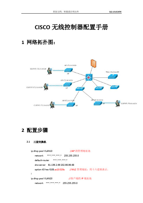
思科无线控制器配置基础
思科无线: 2500 系列无线控制器部署指南新

思科无线控制器配置基础

Presentation_ID
© 2006 Cisco Systems, Inc. All rights reserved.
Cisco Confidential
18
Menu Bar
MONITOR Provides a view of this controller, its APs and wireless clients
© 2006 Cisco Systems, Inc. All rights reserved.
Cisco Confidential
12
Command Line Interface (CLI) “debug” Command
Presentation_ID
© 2006 Cisco Systems, Inc. All rights reserved.
Cisco Confidential
5
Controller Configuration
Single binary configuration file
Important to perform configuration backups No text output Show running configuration is a summary configuration not in command syntax Contains no MAC address information Can be ported to multiple Cisco Airespace Controllers Beware of duplicate IP addresses
Only on 4XXX series
10/100Base-TX Ethernet port which is speed auto-sensing Service Interface Port is not auto-sensing for DTE / DCE
CiscoWLAN控制器的配置详解

关于Cisco控制器的操作系统为IOS系统,初始配置如同Cisco交换机和路由器一样,我们可以使用Console线缆接到WLC(WLAN Ctroller)Console端口对其进行初始化配置,然后再使用GUI的方式进行深入功能的配置。
1、基本配置(1)、配置控制器管理接口配置步骤:∙show interface detailed management*/显示管理接口的设置信息config wlan disable wlan-number*/关闭设备上所有WLAN∙config interface address management ip-addr ip-netmask gateway */配置管理接口的地址、掩码、网关config interface vlan management {vlan-id | 0}*/配置管理接口VLAN,0代表untagged VLAN,非0值代表tagged VLAN,而思科控制器只识别tagged VLAN。
config interface port management physical-ds-port-number*/配置管理接口的物理目的端口config interface dhcpmanagement ip-address-of-primary-dhcp [ip-address-of-secondary-dhcp-serve r]*/配置管理接口的主DHCP服务器和次DHCP服务器。
config interface acl management access-control-list-name*/配置管理接口的ACL(控制列表)∙∙∙∙∙∙∙∙∙save config*/保存配置∙show interface detailed management*/显示管理接口的设置信息(2)、配置AP管理接口配置步骤:∙show interface summary*/显示接口汇总信息∙show interface detailed ap-manager*/显示AP管理接口设置信息config wlan disable wlan-number*/关闭该接wlan通讯config interface address ap-manager ip-addr ip-netmask gateway */配置AP管理接口的IP地址、掩码、网关config interface vlan ap-manager {vlan-id | 0}*/配置AP管理接口的VLAN,0代表untagged VLAN,非0值代表tagged VLAN,而思科控制器只识别tagged VLAN。
思科路由器配置基础
思科路由器配置基础思科路由器配置基础思科(Cisco)路由器是智能信息网络的基础,为当今要求最严格的网络服务,包括IP 通信、视频、客户关系管理、金融交易和其他实时应用提供了高可用性、全面的安全性、易管理性和先进的服务质量( QoS )。
下面店铺准备了思科路由器配置基础,欢迎大家参考!一、基本设置方式一般来说,可以用5种方式来设置路由器:1.Console口接终端或运行终端仿真软件的微机;2.AUX口接MODEM,通过电话线与远方的终端或运行终端仿真软件的微机相连;3.通过Ethernet上的TFTP服务器;4.通过Ethernet上的TELNET程序;5.通过Ethernet上的SNMP网管工作站。
但路由器的第一次设置必须通过第一种方式进行,此时终端的硬件设置如下:波特率:9600数据位:8停止位:1奇偶校验: 无二、命令状态1. router>路由器处于用户命令状态,这时用户可以看路由器的连接状态,访问其它网络和主机,但不能看到和更改路由器的设置内容。
2. router#在router>提示符下键入enable,路由器进入特权命令状态router#,这时不但可以执行所有的用户命令,还可以看到和更改路由器的设置内容。
3. router(config)#在router#提示符下键入configure terminal,出现提示符router(config)#,此时路由器处于全局设置状态,这时可以设置路由器的全局参数。
4. router(config-if)#; router(config-line)#; router(config-router)#;…路由器处于局部设置状态,这时可以设置路由器某个局部的参数。
5. >路由器处于RXBOOT状态,在开机后60秒内按ctrl-break可进入此状态,这时路由器不能完成正常的功能,只能进行软件升级和手工引导。
6. 设置对话状态这是一台新路由器开机时自动进入的状态,在特权命令状态使用SETUP命令也可进入此状态,这时可通过对话方式对路由器进行设置。
思科网络学院教程无线路由器配置

网络管理软件
使用网络管理软件监控路由器的状态和性能,及时发现和解决故障。
流量分析工具
使用流量分析工具监控网络流量,发现异常流量和潜在的故障源。
日志文件
查看路由器的日志文件,了解故障发生的时间和原因,以便进行故障排除。
故障排除工具的使用
定期更新路由器固件
保持路由器固件最新,以获得最新的功能和修复已知的漏洞。
L2TP(二层隧道协议)VPN
L2TP协议结合了PPTP和LACAP协议的特点,提供更高的安全性。在无线路由器上配置L2TP VPN,可以提供更安全的远程访问服务。
OpenVPN
OpenVPN是一种开源的VPN协议,使用SSL/TLS协议进行数据传输加密。在无线路由器上配置OpenVPN,可以提供跨平台的远程访问服务,并具有很高的安全性。
状态检测防火墙
03
状态检测防火墙基于会话状态进行过滤,能够识别和跟踪TCP连接。在无线路由器上配置状态检测防火墙,可以提高网络安全性,防止非法入侵。
无线路由器的防火墙配置
04
无线路由器的故障排除
检查无线信号强度、SSID设置、加密方式等是否正确,重新启动路由器或更换信道。
无线连接问题
网速慢
无法访问互联网
密钥
通过MAC地址过滤功能,限制特定设备的访问权限,增强网络安全。
MAC地址过滤
无线网络的加密与安全设置
配置DHCP服务器的IP地址池,自动为连接到路由器的客户端分配IP地址。
IP地址池
设置IP地址租约时间,即客户端在获取IP地址后可以使用的最长时间。
租约时间
为特定客户端手动分配静态IP地址,满足特定网络需求。
思科网络学院教程无线路由器配置
目录
1 cisco无线控制器配置基础
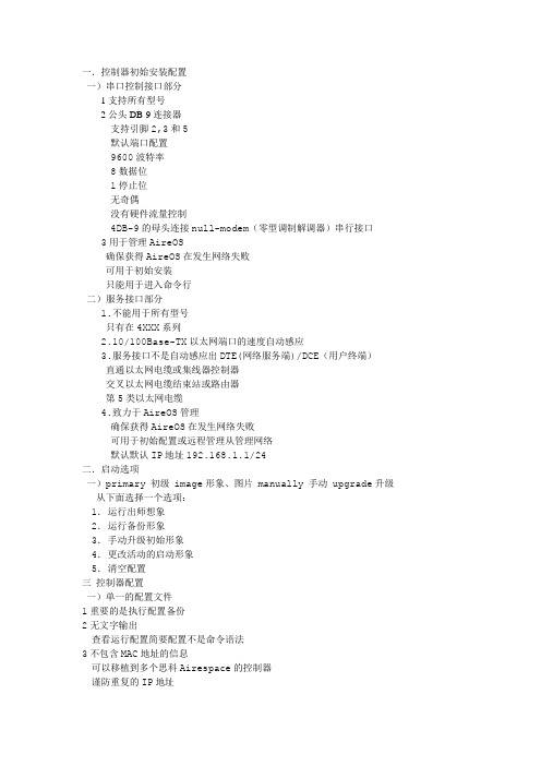
一.控制器初始安装配置一)串口控制接口部分1支持所有型号2公头DB-9连接器支持引脚2,3和5默认端口配置9600波特率8数据位1停止位无奇偶没有硬件流量控制4DB-9的母头连接null-modem(零型调制解调器)串行接口3用于管理AireOS确保获得AireOS在发生网络失败可用于初始安装只能用于进入命令行二)服务接口部分1.不能用于所有型号只有在4XXX系列2.10/100Base-TX以太网端口的速度自动感应3.服务接口不是自动感应出DTE(网络服务端)/DCE(用户终端)直通以太网电缆或集线器控制器交叉以太网电缆结束站或路由器第5类以太网电缆4.致力于AireOS管理确保获得AireOS在发生网络失败可用于初始配置或远程管理从管理网络默认默认IP地址192.168.1.1/24二.启动选项一)primary 初级 image形象、图片 manually 手动 upgrade升级从下面选择一个选项:1.运行出师想象2.运行备份形象3.手动升级初始形象4.更改活动的启动形象5.清空配置三控制器配置一)单一的配置文件1重要的是执行配置备份2无文字输出查看运行配置简要配置不是命令语法3不包含MAC地址的信息可以移植到多个思科Airespace的控制器谨防重复的IP地址二)双配置文件运行配置运行立即生效,有部分命令在保存命令前不会自动保存如果没有保存,将丢失的命令的情况下复位没有保存配置或电源周期保存配置配置保存在NVRAM表演后保存配置命令1其接入点和无线客户端2提供无线局域网的配置,如SSIDs和安全政策的所有用户群体。
3提供控制器配置如层2 / 3模式,组播和移动设置4提供AP配置,客户管理和各种射频设置5提供融入安全结构等的RADIUS连接6提供一体化的网络,如IP地址和SNMP7提供行政选择,如升级和备份Management > Local Management Users一)管理:本地管理用户本地管理的用户界面是在命令行和web界面切换二)管理:http交换机web配置完成并重启机器后,将启动公钥加密保证安全,默认情况下是禁止的。
Cisco 5500 系列无线控制器产品手册说明书
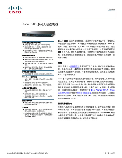
产品手册Cisco 5500 系列无线控制器Cisco ®5500 系列无线控制器是一款高度可扩展的灵活平台,能够在大中型企业和园区环境中,为关键任务无线网络提供系统级服务。
5500 系列专门采用了独特设计,支持 802.11n 的性能下的最大可扩展性,通过射频的监控和保护能力提供延长的正常工作时间,并且可以同时管理 500 个接入点;它具有卓越的性能,可以提供可靠的视频流和长话级音质;它还具有增强的故障恢复功能,能在要求最严格的环境中提供一致的移动体验。
最大限度提高性能和可扩展性● 支持多达 500 个接入点和 7000 个客户端。
● 经过优化的 802.11n 性能,能够提供相当于 802.11a/g 网络九倍的性能。
● 延长的正常运行时间,每个控制器能同时配置和管理 500 个接入点 增强的移动性和服务● 范围更大的移动域,可以同时关联更多客户端。
● 速度更快的射频资源管理 (RRM) 更新,可在用户漫游时提供不间断的网络接入。
● 智能射频控制平面,可以自行配置、修复和优化。
● 高效漫游功能可提升应用性能,例如长话级音质、一致的视频流及数据备份。
许可灵活性与投资保护● 可以根据需要,逐步添加附加接入点容量许可。
OfficeExtend 解决方案● 安全、简便、经济高效的移动远程办公人员解决方案。
● 每个控制器支持多达 500 个远程接入点。
● 通过支持统一通信无线电话,节约手机费用。
全面的有线/无线安全性● 在接入点和控制器之间提供全面的 CAPWAP 加密。
● 支持检测恶意接入点和拒绝服务攻击。
● 管理帧保护功能可以检测恶意用户,并向网络管理员发出警报。
企业无线网状网● 动态无线网状网支持在室内和室外为难以布线的区域提供网络连接。
支持环保● 支持自适应功率管理,可以在非高峰时段关闭接入点无线电设备,以减少功耗。
● OfficeExtend 解决方案通过减少通勤时间和节省汽油、驾驶里程和保险成本,可降低成本和支持环保最佳实践。
思科路由器基本配置教程

思科路由器基本配置教程思科路由器配置过程还是比较复杂的,需要考虑的因素很多,特别在安全方面。
其实没必要把路由器想的那么复杂,其实路由器就是一个具有多个端口的计算机,只不过它在网络中起到的作用与一般的PC不同而已。
如何才能真正的做好思科路由器的配置工作下面,我们就针对这个问题详细的介绍一下。
思科路由器的简介所有思科路由器配置的IOS都是一个嵌入式软件体系结构。
和普通计算机一样,路由器也需要一个操作系统,思科把这个操作系统叫作思科互联网络操作系统,也就是我们知道的IOS。
思科IOS软件提供以下网络服务:可扩展的网络结构、基本的路由和交换功能、可靠和安全的访问网络资。
思科命令行界面(CLI)用一个分等级的结构,这个结构需要在不同的模式下来完成特定的任务。
例如配置一个路由器的接口,用户就必须进入到路由器的接口配置模式下,所有的配置都只会应用到这个接口上。
每一个不同的配置模式都会有特定的命令提示符。
EXEC为IOS软件提供一个命令解释服务,当每一个命令键入后EXEC便会执行该命令。
在第一次进行思科路由器配置的时候,我们需要从console端口来进行配置。
以下就是如何连接到控制端口及设置虚拟终端程序的方法:(1)使用rollover线和一个RJ45和DB9或者DB25的转换适配器连接路由器控制端口和终端计算机。
如何连接到思科路由器的控制端口:控制端口(consoleport)和辅助端口(AUXport)是思科路由器的两个管理端口,这两个端口都可以在第一次进行思科路由器配置时使用,但是我们一般都推荐使用控制端口,因为并不是所有的路由器都会有AUX端口。
(2)当路由器第一次启动时,默认的情况下是没有网络参数的,路由器不能与任何网络进行通信。
所以我们需要一个RS-232ASCLL终端或者计算机仿真ASCLL终端与控制端口进行连接。
(3)连接到CONSOLE端口的方法连接线缆:连接到console端口我们需要一根rollover 线缆和RJ-45转DB-9的适配器。
思科网络学院教程无线路由器配置

配置向导
选择向导
在路由器管理界面中,通常会 有一个“设置向导”或“快速
设置”选项,点击进入。
配置参数
按照向导的提示,输入网络服 务商提供的宽带账号和密码、 选择无线网络的名称(SSID
)和安全模式等参数。
完成配置
完成向导后,路由器会自动进 行相关配置,包括DHCP、 NAT等。
手动配置
网络参数
进入“网络参数”或“高级设置”菜单,手 动设置WAN口参数,如静态IP、动态IP或 PPPoE拨号等。
动态IP地址配置
动态IP地址配置概述
动态IP地址是指由DHCP服务器自动分配的IP地址,适用于终端设备数量较多且经常变动的场景。
动态IP地址配置步骤
在路由器的管理界面上启用DHCP服务,并设置相应的地址池参数,如IP地址范围、租约时间等。终 端设备在连接网络时会自动从地址池中获取IP地址。
04
CATALOGUE
无线设置
在“无线设置”菜单中,可以设置无线网络的基本 参数,如信道、模式、安全等。
其他设置
根据需要,还可以进行其他高级设置,如 MAC地址过滤、家长控制等。
无线网络安全设置
安全模式
选择适合的安全模式,如WPA2-PSK加密方式 。
密钥管理
设置无线网络密码,建议使用强密码并定期更 换。
MAC地址过滤
防火墙问题
检查防火墙设置是否正确,允许必要的网络流量通过 。
05
CATALOGUE
无线路由器发展趋势与展望
无线路由器技术发展趋势
5G技术融合
随着5G技术的普及,无线路由器将逐渐支持5G频段,提 供更高速、稳定的网络连接。
01
Mesh组网技术
Mesh组网技术将逐渐成为无线路由器 的主流配置,实现多台路由器之间的无 缝连接,扩大覆盖范围。
Cisco无线局域网配置基础(第2版)

01
4.7.1 控制器的物 理端口及逻辑接口冗 余
02 4.7.2 LAP的负 载均衡
03
4.7.3 使用WLC的 Web界面配置AP的 主、备、第三控制器
04
4.7.4 使用WCS配 置AP的主、备、第 三控制器
05 4.7.5 控制器冗 余设计
4.5.3 配置Mesh AP的桥 接模式
4.5.5 验证Mesh连接状态
4.5.2 在网络中增加Cisco Mesh AP
4.5.4 配置Mesh AP的角 色
4.5.6 设置全局Mesh参数
4 思科统一无线局域网的配置
4.5 配置Cisco Wireless Mesh网络
4 思科 统一无线 局域网的 配置
E.1 无线网络传输开销分析
E.2 IEEE 802.11b传输性能分 析
E.3 IEEE 802.11a传输性能分 析
E.4 IEEE 802.11g传输性能分 析
13 附录F 术语及缩略语
附录F 术语及缩略语
2020
感谢聆听
D
6.5 重新启 动控制器
E
6 管理无线网络控制器
6.1.1 WCS简 介
6.1.3 使用WCS查 看接入用户的信息
6.1.2 使用 WCS规划热图
6.1 WCS及其配置
6.1.4 使用 WCS自定义报表
6 管理无线网络控制器
壹
6.2.1 使用Web管理 页面升级WLC映像软件
贰
6.2.2 使用CLI命令端 口升级控制器软件
WLC
4.1.5 配 置AP组
4.1.6 配 置移动组
4.1 WLC的基本配置
思科路由器基本配置

思科路由器基本配置
预览说明:预览图片所展示的格式为文档的源格式展示,下载源文件没有水印,内容可编辑和复制
思科路由器基本配置
路由器:2811
支持命令简写,使用Tab键补全,位置在键盘的大小写Cpas Lock 键上面
登陆
配置向导使用no,使用CLI配置路由器(也可以选择yes,使用向导来配置,这里不再详述)
直接回车进入路由器的配置界面
每个模式都可以使用?来查看可以使用的命令
通常使用修改路由器名,以方便知道是在配置那台路由器
123和cisco是随意用的,可以修改成自己的密码,如果两者都设置的话,secret 密码起效
可以使用?查看可以使用的命令,在任意模式下都可以使用,如果有不清楚的命令,可以使用?查看
如果接口是Serial,需要配置clockrate,bandwidth选配
路由的接口是从0开始的,模块化路由器是从0模块的0接口开始的这点区分于交换机
静态路由和缺省路由
重启R#reload。
Cisco无线控制器配置
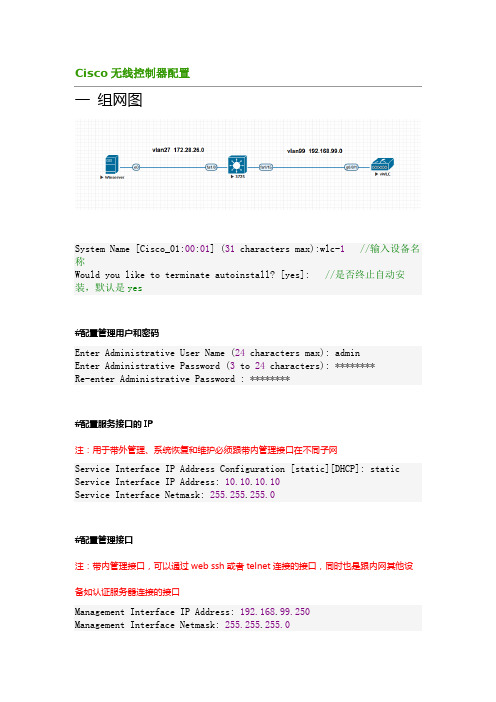
Cisco无线控制器配置一组网图System Name [Cisco_01:00:01] (31 characters max):wlc-1//输入设备名称Would you like to terminate autoinstall? [yes]: //是否终止自动安装,默认是yes#配置管理用户和密码Enter Administrative User Name (24 characters max): adminEnter Administrative Password (3 to 24 characters): ********Re-enter Administrative Password : ********#配置服务接口的IP注:用于带外管理、系统恢复和维护必须跟带内管理接口在不同子网Service Interface IP Address Configuration [static][DHCP]: static Service Interface IP Address: 10.10.10.10Service Interface Netmask: 255.255.255.0#配置管理接口注:带内管理接口,可以通过web ssh或者telnet连接的接口,同时也是跟内网其他设备如认证服务器连接的接口Management Interface IP Address: 192.168.99.250Management Interface Netmask: 255.255.255.0Management Interface Default Router: 192.168.99.254Management Interface VLAN Identifier (0 = untagged): 99Management Interface Port Num [1 to 1]: 1Management Interface DHCP Server IP Address: 192.168.99.254#设置虚拟网关注:为三层漫游而设置的虚拟接口,在同一个mobility group里的WLC都必须配置相同的虚拟接口Virtual Gateway IP Address: 1.1.1.1#配置Mobility/RF Group名称注:用于用户在不同控制器下的AP间的三层漫游,所以不同控制器的该组必须相同Mobility/RF Group Name: test#配置默认的SSID注:LAP加入控制器时将使用它,LAP加入后WLC会把其他的SSID提供给LAP Network Name (SSID): test#dhcp桥接注:Bridging Mode 将会把DHCP 请求透传出去,不做处理;一般都使用WLC本身中继代理功能,默认NO。
无线控制器配置基础课程(PPT110张)

Would you like to terminate autoinstall? [yes]:
System Name [Cisco_51:2b:60] (31 characters max): 2106-demo AUTO-INSTALL: process terminated -- no configuration loaded Enter Administrative User Name (24 characters max): cisco Enter Administrative Password (24 characters max): cisco Re-enter Administrative Password : cisco
44xx WLAN Controller
型号 4402
支持 12, 25, 和50 AP
型号 4404
支持100 APs
*不能通过软件升级AP容量 *4400系列使用SFP光纤模块 *4400系列每port支持50个AP
Presentation_ID © 2006 Cisco Systems, Inc. All rights reserved. Cisco Confidential
Cisco Confidential
2
Presentation Title 准备工作 Size 30PT Option 2: Live
Presentation_ID
© 2006 Cisco Systems, Inc. All rights reserved.
Cisco Confidential
3
基本设备
interface Vlan30 ip address 192.168.30.254 255.255.255.0
思科无线: 2500 系列无线控制器部署指南新
思科路由器设置方法和常见配置命令
思科路由器设置方法和常见配置命令思科路由器设置方法和常见配置命令思科路由器怎么设置,是我们经常遇到的问题,下面店铺准备了关于思科路由器设置方法和常见配置命令,欢迎大家参考学习!一、基本设置方式一般来说,可以用5种方式来设置Cisco思科路由器:1.Console口接终端或运行终端仿真软件的微机;2.AUX口接MODEM,通过电话线与远方的终端或运行终端仿真软件的微机相连;3.通过Ethernet上的TFTP服务器;4.通过Ethernet上的TELNET程序;5.通过Ethernet上的SNMP网管工作站。
但Cisco思科路由器的第一次设置必须通过第一种方式进行,一般用超级终端通过com口进行控制。
此时终端的硬件设置如下: 波特率:9600数据位:8停止位:1奇偶校验: 无二、命令操作Cisco思科路由器所用的操作系统是IOS.共有以下几种状态:1、router>在router>提示符下,Cisco思科路由器处于用户命令状态,这时用户可以看Cisco思科路由器的连接状态,访问其它网络和主机,但不能看到和更改Cisco思科路由器的设置内容。
此时输入?并回车,可以查看到在此状态下可以用的命令。
(IOS允许你在任何时候用这种方式查看在某种状态下可以用的命令)。
在敲入enable并回车后,按照系统提示输入密码,(在新的Cisco思科路由器第一次进行调试的时候不需要输入密码,直接回车即可)进入#提示符,就可以对Cisco思科路由器进行各种操作了。
2、router#Cisco思科路由器进入特权命令状态router#后,不但可以执行所有的用户命令,还可以看到和更改Cisco思科路由器的设置内容。
此时就可以对Cisco思科路由器的名字、密码等进行设置。
3、router(config)#在router#提示符下键入configure terminal,出现提示符router(config)#,此时Cisco思科路由器处于全局设置状态,这时可以设置Cisco思科路由器的全局参数。
思科无线控制器配置基础

44xx WLAN Controller
§ 型号 4402
支持 12, 25, 和50 AP
§ 型号 4404
支持100 APs
Presentation_ID
© 2019 Cisco Systems, Inc. All rights reserved.
无线控制器配置基础
Presentation_ID
© 2019 Cisco Systems, Inc. All rights reserved.
Cisco Confidential
1
PDF 文件使用 "pdfFactory Pro" 试用版本创建 fineprint
基本配置任务及过程
§ 准备工作
1. 控制器启动配置和升级控制器软件版本 2. 熟悉控制器配置界面 3. 连接AP到控制器上
配置3层交换机
§ p dhcp excluded-address 192.168.10.1
§ ip dhcp excluded-address 192.168.10.254
§ ip dhcp excluded-address 192.168.10.2
§! § ip dhcp pool AP
§ network 192.168.10.0 255.255.255.0
PDF 文件使用 "pdfFactory Pro" 试用版本创建 fineprint
$18,890 $10,070
$4,875
5
4400系列无线控制器
§ 1 RU 高度
2口 或者 4口千兆上联
§ 支持 12, 25, 50 or 100 AP § 支持 5000 MAC地址转发表 § 10/100Base-TX 以太网 Service Port § 9 pin 串口Console口 § 2 扩展槽和1个utility port目前未使用 § 2 热插拔电源模块插槽
思科虚拟无线局域网控制器 8.2 配置向导和最佳实践说明书
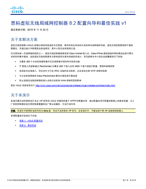
思科虚拟无线局域网控制器 8.2 配置向导和最佳实践 v1最后更新日期:2015 年 11 月 23 日关于本解决方案虚拟无线控制器 (vWLC) 能够以具成本效益的方式管理、保护和优化本地和分支机构无线网络的性能。
虚拟无线控制器有助于服务器整合,并通过减少中断提高业务连续性,是中小型企业的理想之选。
作为思科统一无线网络的组件之一,虚拟无线控制器能够实现 Cisco Aironet 接入点、Cisco Prime 基础设施和思科移动业务引擎之间的实时集中通信。
这款虚拟无线控制器专为具有虚拟化意向的组织而设计,而且能够为中小型企业部署提供以下优势:•为最多 200 个分支机构提供集中式无线网络可视性和可控性功能•IT 管理人员能够通过 FlexConnect 对最多 200 个接入点和 3000 个客户端进行配置、管理和故障排除•实现安全访客接入、符合支付卡行业 (PCI) 法规的非法检测,以及本地交换 Wi-Fi 音频和视频•与分支机构网络的 Cisco FlexConnect 解决方案实现可靠连接•防止连接至远程控制器的接入点因分支机构 WAN 故障而受到影响更多 vWLC 资源信息位于/c/en/us/products/wireless/virtual-wireless-controller/index.html关于本演示本演示展示如何使用运行 8.2.1.97 软件的 vWLC 所提供的基于 HTTP 的配置向导。
通过配置向导可配置控制器上的基本设置。
从工厂收到控制器后或已将控制器重置到出厂默认设置后,可运行该向导。
注意:本演示中使用的当前代码为 Beta 版,而且不支持某些 AP 型号。
在本演示中,不建议用户将 AP 连接到控制器上。
本预配置演示包括以下内容:•场景 1:vWLC 配置向导•场景 2:最佳实践要求下表概括该预配置演示要求。
表 1.演示要求监控工作站•笔记本电脑终端套件首选终端路由器•已为 dCloud 注册并配置的 819W 路由器受支持终端路由器/AP•已为 dCloud 注册并配置的路由器•Cisco Aironet 系列接入点(3000、2000、1000 系列)用户设备•平板电脑/智能手机/笔记本电脑拓扑此内容包含预配置的用户和组件,旨在说明解决方案脚本场景和功能。
cisco无线控制配置说明
cisco⽆线控制配置说明ContentsIntroductionPrerequisitesRequirementsComponents UsedConventionsBackground InformationConfigureNetwork DiagramConfigure the WLC for Basic OperationConfigure the Switch for the WLCConfigure the Switch for the APsVerifyTroubleshootCommandsController Does Not Defend AP-Manager IP AddressTroubleshoot a Lightweight Access Point Not Joininga Wireless LAN ControllerCisco Support Community - Featured ConversationsRelated InformationIntroductionThis document provides a basic configuration example of a lightweight access point (AP) that is connected to a Cisco Wireless LAN (WLAN) Controller (WLC) through a Cisco Catalyst Switch.PrerequisitesRequirementsEnsure that you meet these requirements before you attempt this configuration:Basic knowledge of the configuration of lightweight APs and Cisco WLCsBasic knowledge of Lightweight AP Protocol (LWAPP)Knowledge of the configuration of an external DHCP server and/or domain name server (DNS)Basic configuration knowledge of Cisco switchesComponents UsedThe information in this document is based on these software and hardware versions:Cisco Aironet 1232AG Series Lightweight APCisco 4402 Series WLC that runs firmware 5.2.178.0Microsoft Windows Server 2003 Enterprise DHCP serverThis configuration works with any other Cisco WLC and any lightweight AP.The information in this document was created from the devices in a specific lab environment. All of the devices used in this document started with a cleared (default) configuration. If your network is live, make sure that you understand the potential impact of any command.ConventionsRefer to the Cisco Technical Tips Conventions for more information on document conventions.Background InformationIn order for the WLC to be able to manage the LAP, the LAP should discover the controller and register with the WLC. There are different methods that an LAP uses in order to discover the WLC. For detailed information on the different methods the LAPs use to register to the WLCs, refer to Lightweight AP (LAP) Registration to a Wireless LAN Controller (WLC)This document describes the configuration steps needed to register the LAP to the WLC and for basic operation of the LWAPP wireless network.ConfigureIn order to register the LAP to the WLC and for basic operation of the LWAPP wireless network, complete these steps:1.Have a DHCP server present so that the APs can acquire a networkaddress.Note: Option 43 is used if the APs reside in a different subnet.2.Configure the WLC for basic operation.3.Configure the switch for the WLC.4.Configure the switch for the APs.5.Register the lightweight APs to the WLCs.Note: Use the Command Lookup Tool (registered customers only) in order to obtain more information on the commands used in this section.Network DiagramThis document uses this network setup:Configure the WLC for Basic OperationWhen the controller boots at factory defaults, the bootup script runs the configuration wizard, which prompts the installer for initial configuration settings. This procedure describes how to use the configuration wizard on the command-line interface (CLI) in order to enter initial configuration settings.Note: Be sure that you understand how to configure an external DHCP server and/or DNS.Complete these steps in order to configure the WLC for basicoperation:1.Connect your computer to the WLC with a DB-9 null modem serial cable.2.Open a terminal emulator session with these settings:o9600 baudo8 data bitso 1 stop bito No parityo No hardware flow control3.At the prompt, log in to the CLI.The default username is admin, and the default password is admin.4.If necessary, enter reset system in order to reboot the unit andstart the wizard.5.At the first wizard prompt, enter a system name. The system namecan include up to 32 printable ASCII characters.6.Enter an administrator user name and password. The user name andpassword can include up to 24 printable ASCII characters.7.Enter the service-port interface IP configuration protocol, eithernone or DHCP.Enter none if you do not want to use the service port or if you want to assign a static IP address to the service port. 8.If you entered none in step 7 and need to enter a static IP addressfor the service port, enter the service-port interface IP address and netmask for the next two prompts.If you do not want to use the service port, enter 0.0.0.0 for the IP address and netmask.9.Enter values for these options:o Management interface IP addresso Netmasko Default router IP addresso Optional VLAN identifierYou can use a valid VLAN identifier or 0 for untagged.10.Note: When the management interface on the controller isconfigured as part of the 'native vlan' on the switchport to which it connects, the controller should NOT tag the frames. Therefore, you must set the VLAN to be zero (on the controller).11.Enter the Network Interface (Distribution System) Physical Portnumber.For the WLC, the possible ports are 1 through 4 for a front-panel gigabit Ethernet port.12.Enter the IP address of the default DHCP server that supplies IPaddresses to clients, the management interface, and theservice-port interface, if you use one.13.Enter the LWAPP Transport Mode, either LAYER2 or LAYER3.Note: If you configure the WLC 4402 via Wizard and select AP transport Mode LAYER2, the Wizard does not ask the details of AP Manager.14.Enter the Virtual Gateway IP Address.This address can be any fictitious, unassigned IP address, such as1.1.1.1, for the Layer 3 Security and Mobility managers to use.Note: Usually the Virtual Gateway IP Address that is used is a private address.15.Enter the Cisco WLAN Solution Mobility Group/RF Group name.16.Enter the WLAN 1 service set identifier (SSID) or network name.This identifier is the default SSID that lightweight APs use in order to associate to a WLC.17.Allow or disallow Static IP Addresses for clients.Enter yes in order to allow clients to supply their own IP addresses.Enter no in order to require clients to request an IP address froma DHCP server.18.If you need to configure a RADIUS server on the WLC, enter yes andenter this information:o RADIUS server IP addresso The communication porto The shared secretIf you do not need to configure a RADIUS server or you want to configure the server later, enter no.19.Enter a country code for the unit.Enter help in order to see a list of the supported countries.20.Enable and disable support for IEEE 802.11b, IEEE 802.11a, and IEEE802.11g.21.Enable or disable radio resource management (RRM) (auto RF).WLC 4402—Configuration WizardWelcome to the Cisco Wizard Configuration ToolUse the '-' character to backupSystem Name [Cisco_43:eb:22]: c4402Enter Administrative User Name (24 characters max): adminEnter Administrative Password (24 characters max): *****Service Interface IP Address Configuration [none][DHCP]: noneEnable Link Aggregation (LAG) [yes][NO]: No Management Interface IP Address:192.168.60.2Management Interface Netmask:255.255.255.0Management Interface Default Router: 192.168.60.1Management Interface VLAN Identifier (0 = untagged): 60Management Interface Port Num [1 to 2]: 1 Management Interface DHCP Server IP Address: 192.168.60.25AP Transport Mode [layer2][LAYER3]: LAYER3 AP Manager Interface IP Address:192.168.60.3AP-Manager is on Management subnet, using same valuesAP Manager Interface DHCP Server(192.168.50.3): 192.168.60.25Virtual Gateway IP Address: 1.1.1.1 Mobility/RF Group Name: RFgroupname Network Name (SSID): SSIDAllow Static IP Addresses [YES][no]: yes Configure a RADIUS Server now? [YES][no]: no Enter Country Code (enter 'help' for a list of countries) [US]: USEnable 802.11b Network [YES][no]: yes Enable 802.11a Network [YES][no]: yes Enable 802.11g Network [YES][no]: yes Enable Auto-RF [YES][no]: yesNote: The management interface on the WLC is the only consistently pingable interface from outside of the WLC. So it is an expected behavior if you are not able to ping the AP manager interface from outside of the WLC.Note: You must configure the AP manager interface in order for the APs to associate with the WLC.Configure the Switch for the WLCThis example uses a Catalyst 3750 switch that uses only one port. The example tags the AP-manager and management interfaces and places these interfaces on VLAN 60. The switch port is configured as an IEEE 802.1Q trunk and only the appropriate VLANs, which are VLANs 2 through 4 and 60 in this case, are allowed on the trunk. The management and AP-manager VLAN (VLAN 60) is tagged and is not configured as the native VLAN of the trunk. So when the example configures those interfaces on the WLC, the interfaces are assigned a VLAN identifier.This is an example 802.1Q switch port configuration:interface GigabitEthernet1/0/1description Trunk Port to Cisco WLCswitchport trunk encapsulation dot1qswitchport trunk allowed vlan 2-4,60switchport mode trunkno shutdownNote: When you connect the WLC gigabit port, make sure it is connected to the switch gigabit port only. If you connect the WLC gigabit Ethernet to the Switch FastEthernet port then it will not work.Notice that this configuration example configures the neighbor switch port in a way that only allows relevant VLANs on the 802.1Q trunk. All other VLANs are pruned. This type of configuration is not necessary, but it is a deployment best practice. When you prune irrelevant VLANs, the WLC only processes relevant frames, which optimizes performance.Configure the Switch for the APsThis is an example VLAN interface configuration from the Catalyst 3750: interface VLAN5description AP VLANip address 10.5.5.1 255.255.255.0While the Cisco WLCs always connect to 802.1Q trunks, Cisco lightweight APs do not understand VLAN tagging and should only be connected to the access ports of the neighbor switch.This is an example switch port configuration from the Catalyst 3750:interface GigabitEthernet1/0/22description Access Port Connection to Cisco Lightweight APswitchport access vlan 5switchport mode accessno shutdownThe infrastructure is now ready for connection to the APs. The LAPs use the different WLC discovery methods and select a WLC to join. The LAP then registers with the controller.Here is a link to a video on the Cisco Support Community that explainsthe initial configuration of Wireless LAN Controller using the CLI and GUI: Initial configuration of Wireless LAN Controller using the CLI andGUIVerifyUse this section in order to confirm that your configuration works properly.After the LAPs register with the controller, you can view them under Wireless at the top of the user interface of the controller:On the CLI, you can use the show ap summary command in order to verify that the LAPs registered with the WLC: (Cisco Controller) >show ap summaryNumber of APs (1)Global AP User Name.............................. Not Configured Global AP Dot1x User Name........................ Not ConfiguredAP Name Slots AP Model Ethernet MAC Location Port Country Priority------------------ ----- ------------------- --------------------------------- ---- ------- ------AP001b.d4e3.a81b 2 AIR-LAP1232AG-A-K9 00:1b:d4:e3:a8:1b default location 2 IN 1On the WLC CLI, you can also use the show client summary command in order to see the clients that are registered with the WLC:(Cisco Controller) >show client summaryNumber of Clients (1)MAC Address AP Name Status WLAN Auth Protocol Port----------------- ------------- ------------- ---- ---- -------- ----00:40:96:a1:45:42 ap:64:a3:a0 Associated 4 Yes 802.11a 1(Cisco Controller) >Here is a video demonstration that explains how to perform the initial configuration of a Wireless LAN Controller using the GUI and CLI: InitialConfiguration of Wireless Lan Controller using CLI and GUITroubleshootUse this section in order to troubleshoot your configuration. CommandsUse these commands in order to troubleshoot your configuration.Note: Refer to Important Information on Debug Commands before you use debug commands.This debug lwapp events enable WLC command output shows that the lightweight AP gets registered to the WLC: (Cisco Controller) >debug lwapp events enableTue Apr 11 13:38:47 2006: Received LWAPP DISCOVERY REQUEST from AP00:0b:85:64:a3:a0 to ff:ff:ff:ff:ff:ff on port '1'Tue Apr 11 13:38:47 2006: Successful transmission of LWAPPDiscovery-Responseto AP 00:0b:85:64:a3:a0 on Port 1Tue Apr 11 13:38:58 2006: Received LWAPP JOIN REQUEST from AP00:0b:85:64:a3:a0 to 00:0b:85:33:a8:a0 on port '1'Tue Apr 11 13:38:58 2006: LWAPP Join-Request MTU path from AP00:0b:85:64:a3:a0is 1500, remote debug mode is 0Tue Apr 11 13:38:58 2006: Successfully added NPU Entry for AP00:0b:85:64:a3:a0 (index 48) Switch IP: 192.168.60.2, Switch Port: 12223,intIfNum 1, vlanId 60 AP IP: 10.5.5.10, AP Port: 19002, next hop MAC: 00:0b:85:64:a3:a0Tue Apr 11 13:38:58 2006: Successfully transmission of LWAPP Join-Reply to AP00:0b:85:64:a3:a0Tue Apr 11 13:38:58 2006: Register LWAPP event for AP00:0b:85:64:a3:a0 slot 0Tue Apr 11 13:38:58 2006: Register LWAPP event for AP 00:0b:85:64:a3:a0 slot 1Tue Apr 11 13:39:00 2006: Received LWAPP CONFIGURE REQUEST from AP00:0b:85:64:a3:a0 to 00:0b:85:33:a8:a0Tue Apr 11 13:39:00 2006: Updating IP info for AP 00:0b:85:64:a3:a0 -- static 0, 10.5.5.10/255.255.255.0, gtw 192.168.60.1 Tue Apr 11 13:39:00 2006: Updating IP 10.5.5.10 ===> 10.5.5.10 for AP 00:0b:85:64:a3:a0Tue Apr 11 13:39:00 2006: spamVerifyRegDomain RegDomain set for slot 0 code 0regstring -A regDfromCb -ATue Apr 11 13:39:00 2006: spamVerifyRegDomain RegDomain set for slot 1 code 0regstring -A regDfromCb -ATue Apr 11 13:39:00 2006: spamEncodeDomainSecretPayload:Send domain secretMobilityGroup<6f,39,74,cd,7e,a4,81,86,ca,32,8c,06,d3,ff,ec,6d,95,10,99,dd>to AP 00:0b:85:64:a3:a0Tue Apr 11 13:39:00 2006: Successfully transmission of LWAPPConfig-Message to AP 00:0b:85:64:a3:a0Tue Apr 11 13:39:00 2006: Running spamEncodeCreateVapPayload for SSID 'SSID'Tue Apr 11 13:39:00 2006: AP 00:0b:85:64:a3:a0 associated. Last AP failure wasdue to Configuration changes, reason: operator changed 11g mode Tue Apr 11 13:39:00 2006: Received LWAPP CHANGE_STATE_EVENT from AP 00:0b:85:64:a3:a0Tue Apr 11 13:39:00 2006: Successfully transmission of LWAPPChange-State-EventResponse to AP 00:0b:85:64:a3:a0Tue Apr 11 13:39:00 2006: Received LWAPP Up event for AP 00:0b:85:64:a3:a0 slot 0!Tue Apr 11 13:39:00 2006: Received LWAPP CONFIGURE COMMAND RES from AP 00:0b:85:64:a3:a0Tue Apr 11 13:39:00 2006: Received LWAPP CHANGE_STATE_EVENT from AP 00:0b:85:64:a3:a0Tue Apr 11 13:39:00 2006: Successfully transmission of LWAPPChange-State-EventResponse to AP 00:0b:85:64:a3:a0Tue Apr 11 13:39:00 2006: Received LWAPP Up event for AP00:0b:85:64:a3:a0 slot 1!This output shows these useful WLC debug commands:debug pem state enable—Configures the access policy manager debug optionsdebug pem events enabledebug dhcp message enable—Shows the debug of DHCP messages that are exchanged to and from the DHCP server debug dhcp packet enable—Shows the debug of DHCP packet details that are sent to and from the DHCP serverTue Apr 11 14:30:49 2006: Applied policy for mobile 00:40:96:a1:45:42 Tue Apr 11 14:30:49 2006: STA [00:40:96:a1:45:42,192.168.1.41] Replacing FastPath rule type = Airespace AP Client on AP 00:0B:85:64:A3:A0, slot 0InHandle = 0x00000000, OutHandle = 0x00000000 ACL Id = 255, Jumbo Frames= NO, interface = 1 802.1P = 0, DSCP = 0, TTue Apr 11 14:30:49 2006: Successfully plumbed mobile rule for mobile 00:40:96:a1:45:42 (ACL ID 255)Tue Apr 11 14:30:49 2006: Plumbed mobile LWAPP rule on AP00:0b:85:64:a3:a0for mobile 00:40:96:a1:45:42Tue Apr 11 14:30:53 2006: DHCP proxy received packet, src: 0.0.0.0, len = 320Tue Apr 11 14:30:53 2006: dhcpProxy: Received packet: Client00:40:96:a1:45:42DHCP Op: BOOTREQUEST(1), IP len: 320, switchport: 1, encap: 0xec03 Tue Apr 11 14:30:53 2006: dhcpProxy(): dhcp request, client:00:40:96:a1:45:42: dhcp op: 1, port: 1, encap 0xec03, old mscbport number: 1Tue Apr 11 14:30:53 2006: dhcp option len, including the magic cookie = 84Tue Apr 11 14:30:53 2006: dhcp option: received DHCP REQUEST msgTue Apr 11 14:30:53 2006: dhcp option: skipping option 61, len 7Tue Apr 11 14:30:53 2006: dhcp option: requested ip = 192.168.1.41 Tue Apr 11 14:30:53 2006: dhcp option: skipping option 12, len 15Tue Apr 11 14:30:53 2006: dhcp option: skipping option 81, len 19Tue Apr 11 14:30:53 2006: dhcp option: vendor class id = MSFT 5.0 (len 8)Tue Apr 11 14:30:53 2006: dhcp option: skipping option 55, len 11Tue Apr 11 14:30:53 2006: dhcpParseOptions: options end, len 84, actual 84Tue Apr 11 14:30:53 2006: mscb->dhcpServer: 192.168.60.2,mscb->dhcpNetmask:255.255.255.0,mscb->dhcpGateway: 192.168.60.1, mscb->dhcpRelay:192.168.60.2 VLAN: 60Tue Apr 11 14:30:53 2006: Local Address: 192.168.60.2, DHCP Server: 192.168.60.2, Gateway Addr: 192.168.60.2, VLAN: 60, port: 1Tue Apr 11 14:30:53 2006: DHCP Message Type received: DHCP REQUEST msg Tue Apr 11 14:30:53 2006: op: BOOTREQUEST, htype: Ethernet, hlen: 6, hops: 1Tue Apr 11 14:30:53 2006: xid: 3371152053, secs: 0, flags: 0Tue Apr 11 14:30:53 2006: chaddr: 00:40:96:a1:45:42Tue Apr 11 14:30:53 2006: ciaddr: 0.0.0.0, yiaddr: 0.0.0.0Tue Apr 11 14:30:53 2006: siaddr: 0.0.0.0, giaddr: 192.168.60.2Tue Apr 11 14:30:53 2006: Forwarding DHCP packet locally (348 octets) from 192.168.60.2 to 192.168.60.2Tue Apr 11 14:30:53 2006: Received 348 byte dhcp packet from 0x0201a8c0 192.168.60.2:68Tue Apr 11 14:30:53 2006: DHCP packet: 192.168.60.2 -> 192.168.60.2 using scope "InternalScope"Tue Apr 11 14:30:53 2006: received REQUESTTue Apr 11 14:30:53 2006: Checking node 192.168.1.41 Allocated 1144765719,Expires 1144852119 (now: 1144765853)Tue Apr 11 14:30:53 2006: adding option 0x35Tue Apr 11 14:30:53 2006: adding option 0x36Tue Apr 11 14:30:53 2006: adding option 0x33Tue Apr 11 14:30:53 2006: adding option 0x03Tue Apr 11 14:30:53 2006: adding option 0x01Tue Apr 11 14:30:53 2006: dhcpd: Sending DHCP packet(giaddr:192.168.60.2)to192.168.60.2:67 from 192.168.60.2:1067Tue Apr 11 14:30:53 2006: sendto (548 bytes) returned 548Tue Apr 11 14:30:53 2006: DHCP proxy received packet, src: 192.168.60.2, len = 548Tue Apr 11 14:30:53 2006: dhcpProxy: Received packet: Client00:40:96:a1:45:42DHCP Op: BOOTREPLY(2), IP len: 548, switchport: 0, encap: 0x0Tue Apr 11 14:30:53 2006: dhcp option len, including the magic cookie = 312Tue Apr 11 14:30:53 2006: dhcp option: received DHCP ACK msgTue Apr 11 14:30:53 2006: dhcp option: server id = 192.168.60.2Tue Apr 11 14:30:53 2006: dhcp option: lease time (seconds) = 86400 Tue Apr 11 14:30:53 2006: dhcp option: gateway = 192.168.60.1Tue Apr 11 14:30:53 2006: dhcp option: netmask = 255.255.255.0Tue Apr 11 14:30:53 2006: dhcpParseOptions: options end, len 312, actual 64Tue Apr 11 14:30:53 2006: DHCP Reply to AP client: 00:40:96:a1:45:42, frame len 412, switchport 1Tue Apr 11 14:30:53 2006: DHCP Message Type received: DHCP ACK msgTue Apr 11 14:30:53 2006: op: BOOTREPLY, htype: Ethernet, hlen: 6, hops: 0Tue Apr 11 14:30:53 2006: xid: 3371152053, secs: 0, flags: 0Tue Apr 11 14:30:53 2006: chaddr: 00:40:96:a1:45:42Tue Apr 11 14:30:53 2006: ciaddr: 0.0.0.0, yiaddr: 192.168.1.41Tue Apr 11 14:30:53 2006: siaddr: 0.0.0.0, giaddr: 0.0.0.0Tue Apr 11 14:30:53 2006: server id: 1.1.1.1 rcvd server id:192.168.60.2You can use these additional debug commands in order to troubleshoot your configuration:debug lwapp errors enable—Shows output of the debug of LWAPP errors debug pm pki enable—Shows the debug ofcertificate messages that are passed between the AP and the WLCController Does Not Defend AP-Manager IP AddressThis issues is a result of bug CSCsg75863. If the user accidently injects a device on the subnet that uses the AP-manager IP address of the controller, the Address Resolution Protocol (ARP) cache on the default gateway router is refreshed with the wrong MAC address. When this occurs, the APs can no longer reach the controller and drop into their discovery phase to look for a controller. The APs send discovery requests, and the controller responds with discovery replies, but the JOIN requests never reach the AP-manager interface of the controller because of the bad ARP entry on the gateway router. After the default 4 hour ARP refresh interval, the APs join the controller if the device is removed.A workaround for this issue is to configure the static ARP entries on the gateway router of the controller for these IP addresses:Management IP address—Customers gain access to the graphical user interface (GUI) from another subnet, and the controller receives the AP discovery requests.AP-Manager IP address—APs join the controller from another subnet.Every Dynamic interface IP address—Packets from other subnets reach the dynamic interface of the controller.DHCP packets transmit from the interface of the wireless client. Telnet or SSH to the gateway address of the controller, and use the arp command in order to add the ARP entries. Use the ping command on the default router of the controller to the different addresses in order to refresh the ARP cache on the router. In order to discover the MAC addresses, use this command: show arp | include .Troubleshoot a Lightweight Access Point Not Joining a Wireless LAN ControllerRefre to Troubleshoot a Lightweight Access Point Not Joining a Wireless LAN Controller for information on some of the issues why a Lightweight Access Point (LAP) fails to join a WLC and how to troubleshoot the issues.Cisco Support Community - Featured ConversationsCisco Support Community is a forum for you to ask and answer questions, share suggestions, and collaborate with your peers. Below are just some of the most recent and relevant conversations happening right now.。
Cisco思科无线AP的基本配置是什么
Cisco思科无线AP的基本配置是什么CISCO无线AP的基础配置这里是一个无线AP的基本配置向导:Cisco Access Point Basic Config Manual首先,我们要先得用AP的Console口进去,给interface BVI1配置一个IP地址,CISCO的AP BVI接口IP地址出厂值为 10.0.0.1,默认用户名是cisco,密码Cisco(第一个C为大写);我们从配置模式进入BVI接口,做如下配置:interface BVI1ip address 192.168.123.201 255.255.255.01、修改无线SSID在IE浏览器地址栏中输入刚才配置的AP的管理地址(192.168.123.201),在认证对话框中输入管理密码,进入 AP的WEB 管理界面。
在左边的选项卡中,选择“EXPRESS SECURITY”,进入SSID管理界面。
输入新的SSID,记得勾选“Broadcast SSID in Beacon”选项,把SSID广播出去,否则在客户端的无线列表中,将看不到我们新建的SSID。
如果需要安全选项,请在3.Security设置。
2、启用无线接口AP的默认配置无线接口是关闭的,因此即使配置了SSID,我们还是在无线客户端上搜索不到这个SSID。
选择左边栏“Network Interfaces”--“Radio0-802.11G”(相信绝大部分用户都是用802.11G的),--Settings,我们可以看到当前的状态是“Disabled”和“Down”,把Enable Radio右边的单选项“Enable”勾选上,点击“Apply”,如果想快点看到效果,建议把AP重启一下。
接口的状态是下图这个样子就对了,无线AP就能正常工作,执行基本的无线AP的功能3.修改管理员密码选择“SECURITY”下的“Admin Access”,系统默认“Administrator Authenticate By: Default Authentication (Global Password)”,因此,我们在第二栏的“Default Authentication (Global Password)”修改管理员密码。
cisco无线控制器配置基础
AUTO-INSTALL: process terminated -- no configuration loaded
cisco_2504
Enter Administrative User Name (24 characters max): admin
Enter Administrative Password (3 to 24 characters): ***********
(Cisco Controller)
Welcome to the Cisco Wizard Configuration Tool Use the '-' character to backup Would you like to terminate autoinstall? [yes]: yes
System Name [Cisco_e2:5b:e4] (31 characters max):
!
interface GigabitEthernet1/0/6 //接控制器 2 号口,该接口必须是 TRUNK 口 switchport trunk encapsulation dot1q switchport trunk native vlan 200 //控制器所属 VLAN switchport mode trunk
Allow Static IP Addresses [YES][no]: yes
Configure a RADIUS Server now? [YES][no]: no Warning! The default WLAN security policy requires a RADIUS server. Please see documentation for more details.
- 1、下载文档前请自行甄别文档内容的完整性,平台不提供额外的编辑、内容补充、找答案等附加服务。
- 2、"仅部分预览"的文档,不可在线预览部分如存在完整性等问题,可反馈申请退款(可完整预览的文档不适用该条件!)。
- 3、如文档侵犯您的权益,请联系客服反馈,我们会尽快为您处理(人工客服工作时间:9:00-18:30)。
系统启动界面和配置 (OS 5.1)
§ Would you like to terminate autoinstall? [yes]:
§ System Name [Cisco_51:2b:60] (31 characters max): 2106-demo § AUTO-INSTALL: process terminated -- no configuration loaded
§ 支持PCI认证
§ WLC2100 硬件
8个FE口, 2个上联口,6个下联口 其中2个FE口有以太网供电
§ 未使用端口
2个USB端口和一个扩展槽留作 将来扩展用
AIR-WLC2125-K9 AIR-WLC2112-K9 AIR-WLC2106-K9
2100 Series WLAN Controller for up to 25 Lightweight APs 2100 Series WLAN Controller for up to 12 Lightweight APs 2100 Series WLAN Controller for up to 6 Lightweight APs
§ Configure a NTP server now? [YES][no]: no § Configure the system time now? [YES][no]: § Enter the date in MM/DD/YY format: 09/28/08 § Enter the time in HH:MM:SS format: 17:11:00
§ default-router 192.168.10.254 §! § interface FastEthernet0/1 § switchport trunk encapsulation dot1q § switchport mode trunk § …… § interface Vlan1 § ip address 192.168.10.254 255.255.255.0 §! § interface Vlan20 § ip address 192.168.20.254 255.255.255.0 §! § interface Vlan30 §
Presentation_ID
© 2019 Cisco Systems, Inc. All rights reserved.
Cisco Confidential
4
PDF 文件使用 "pdfFactory Pro" 试用版本创建 fineprint
2100系列无线控制器
§ 支持802.11a/b/g/n
: cisco
§ Management Interface IP Address: 192.168.10.1 § Management Interface Netmask: 255.255.255.0 § Management Interface Default Router: 192.168.10.254 § Management Interface VLAN Identifier (0 = untagged): § Management Interface Port Num [1 to 8]: 1 § Management Interface DHCP Server IP Address: 192.168.10.254
实验拓扑示例
VLAN1
PC//AAA服务器
SSID:VLAN20
SSC
TRUNK
fa0/1
Si
port 1
VLAN1/20/30/40 WLC
说明:
1、VLAN1用于连接控制器、AP和 ACS; 2、VLAN20用于WPA/WPA2认证, 认证服务器用ACS。 3、VLAN30用作OPEN/WEP/GUEST 客户接入 3、VLAN40用作WPA/WPA2认证,
§ AP Manager Interface IP Address: 192.168.10.2 § AP-Manager is on Management subnet, using same values § AP Manager Interface DHCP Server (192.168.10.254): § Virtual Gateway IP Address: 1.1.1.1
Presentation_ID
© 2019 Cisco Systems, Inc. All rights reserved.
Cisco Confidential
2
PDF 文件使用 "pdfFactory Pro" 试用版本创建 fineprint
准PSrize备ese3工n0taP作tTion Title Option 2: Live
Presentation_ID
© 2019 Cisco Systems, Inc. All rights reserved.
Cisco Confidential
3
PDF 文件使用 "pdfFactory Pro" 试用版本创建 fineprint
基本设备
§ 控制器 4400或者2100系列 § AP:1130或者1240系列 § 交换机: 最好是3560 POE交换机
SSID:VLAN30 认证用本地EAP
SSC
Presentation_ID
© 2019 Cisco Systems, Inc. All rights reserved.
Cisco Confidential
PDF 文件使用 "pdfFactory Pro" 试用版本创建 fineprint
所有3层网关设置在3层交换机上,地址2548
§ Enter Country Code list (enter 'help' for a list of countries) [US]: CN
§ Enable 802.11b Network [YES][no]: § Enable 802.11a Network [YES][no]: § Enable 802.11g Network [YES][no]: § Enable Auto-RF [YES][no]:
系统启动界面(续)
§ Enable Symmetric Mobility Tunneling [yes][NO]: yes
§ Network Name (SSID): open § Allow Static IP Addresses [YES][no]:
§ Configure a RADIUS Server now? [YES][no]: no § Warning! The default WLAN security policy requires a RADIUS server. § Please see documentation for more details.
Cisco Confidential
6
PDF 文件使用 "pdfFactory Pro" 试用版本创建 fineprint
准备工作
§ 网线和Console线。如果是4400,需要两头是DB9接口的线,如果 是2106或者ISR,需要DB9+RJ45的线
§ 如果是4400,需要GLC光纤模块和光纤 § 确认控制器版本是否需要升级 (用命令show sysinfo查看系统版本) § 是否需要将胖AP升级到瘦AP
启动选项
按5清空配置
Presentation_ID
© 2019 Cisco Systems, Inc. All rights reserved.
Cisco Confidential
PDF 文件使用 "pdfFactory Pro" 试用版本创建 fineprint
The controller boot sequence will always have these option available since this is set in PROM to ensure controller recovery options
思科无线控制器配置基础
单击此处添加副标题内容
无线控制器配置基础
Presentation_ID
© 2019 Cisco Systems, Inc. All rights reserved.
Cisco Confidential
1
PDF 文件使用 "pdfFactory Pro" 试用版本创建 fineprint
© 2019 Cisco Systems, Inc. All rights reserved.
Cisco Confidential
PDF 文件使用 "pdfFactory Pro" 试用版本创建 fineprint
非常重要, Controller的 wireless的 domain要和AP 一致。
11
基本配置任务及过程
§ 准备工作
1. 控制器启动配置和升级控制器软件版本 2. 熟悉控制器配置界面 3. 连接AP到控制器上
§ 配置任务
1. 思科CSSC无线客户端的安装和简单配置 2. 构建一个OPEN和一个WEP的无线网络 3. 构建一个简单WEB认证的无线网络 4. 构建一个支持本地EAP认证的无线网络 5. 构建一个用ACS做AAA认证的无线网络
§ Enter Administrative User Name (24 characters max): cisco
§ Enter Administrative Password (24 characters max): cisco
§ Re-enter Administrative Password
配置3层交换机
§ p dhcp excluded-address 192.168.10.1