基于TRF7960射频读卡器的设计
RFID读卡器射频电路设计
RFID读卡器射频电路设计射频识别技术(RFID,即Radio Frequency Identification)是一种基于雷达技术发展而来的识别技术,其主要原理是通过无线电磁波进行非接触双向数据通信从而获取相关数据并实现目标识别,RFID技术是微波技术、密码学以及无线通信原理等众多学科知识交叉的新兴产物,其应用领域覆盖了高速公路收费管理、铁路物流运输控制管理及工业自动化监控等众多领域。
RFID系统按照工作频段可以划分为低频(135kHz以下)、高频(13.56MHz)、超高频(860~930MHz)和微波(2.4GHz以上)等几类。
射频识别系统通常由电子标签(射频标签)、天线和阅读器组成。
一、读卡器读卡器一般由射频信号处理模块、基带信号处理模块、控制单元以及和外部设备连接的接口模块等组成,其结构。
射频信号处理模块主要实现三大功能:一是通过天线发射足够功率的射频电磁波,以激发电子标签并为其提供能量;二是对发射信号进行调制,然后将已调制的信号数据转化为电磁波传送给标签;三是接收并解调来自电子标签的射频信号。
为了处理往来于应答器的两个方向上的数据流,射频信号处理模块有两个不同的信号通道,传送到电子标签中去的数据通过发射电路分支,而来自于电子标签的数据通过接收电路分支处理。
控制单元的主要功能:与上层应用软件进行通信,并执行应用软件发来的命令;控制与电子标签的通信过程;信号的编码与解码。
对于某些特定系统还有以下的附加功能:执行防碰撞算法;对电子标签与读卡器之间要传送的数据进行加密和解密;进行电子标签和读卡器之间双向的身份验证。
二、射频信号处理单元电路读卡器的发射信号功率远大于电子标签反向散射回来的信号,而且与接收信号同频率,这样如果大功率的反射信号漏泄到接收电路就会使接收电路各个部分的器件饱和,导致读卡器对接收信号无法解调,因此射频信号处理模块的技术指标好坏会直接影响到RFID系统的质量水平。
为射频前端电路结构示意图,射频信号处理模块一般包括两大单元:一是基带信号调制发射模块电路,它由锁相环电路、混频调制电路、滤波电路、功率放大电路等几部分组成;二是射频信号解调接收处理电路,它由差分放大电路,零中频解调电路以及相应的滤波电路构成。
基于单片机的智能牛奶箱系统研究与设计
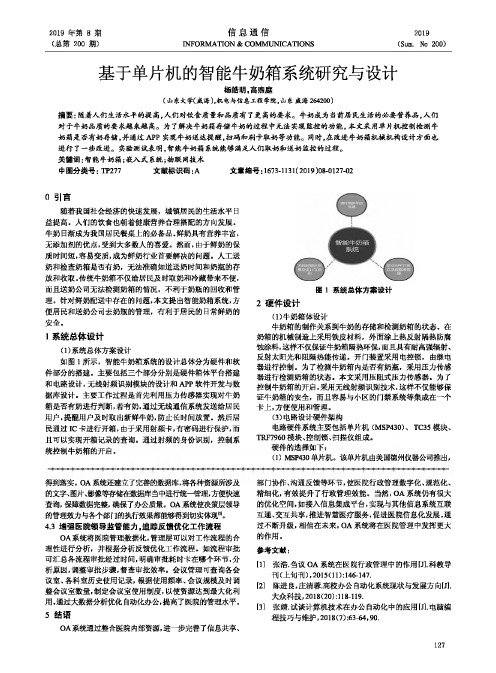
2019年第8期信息通信2019 (总第200期)INFORMATION&COMMUNICATIONS(Sum.No200)基于单片机的智能牛奶箱系统研究与设计杨皓明,高煦庭(山东大学(威海),机电与信息工程学院,山东威海264200)摘要:随着人们生活水平的提高,人们对饮食质量和品质有了更高的要求。
牛奶成为当前居民生活■的必要营养品,人们对于牛奶品质的要求越来越高。
为了解决牛奶箱存储牛奶的过程中无法实现监挫的功能,本文采用单片机控制检测牛奶箱是否有奶存储,并通过APP实现牛奶送达提醒,扫码和刷卡取奶等功能。
同时,在改进牛奶箱机械机构设计方面也进行了一些改进。
实验测试表明,智能牛弼箱系统能够满足人们取弼和送弼监控的过程。
关键词:智能牛奶箱;嵌入式系统;物联网技术中图分类号:TP277文献标识码:A文章编号:1673-1131(2019)08-0127-020引言随着我国社会经济的快速发展,城镇居民的生活水平日益提高。
人们的饮食也朝着健康营养合理搭配的方向发展。
牛奶日渐成为我国居民餐桌上的必备品。
鲜奶具有营养丰富,无添加剂的优点,受到大多数人的喜爱。
然而,由于鲜奶的保质时间短,容易变质,成为鲜奶行业首要解决的问题。
人工送奶和检査奶箱是否有奶,无法准确知道送奶时间和奶瓶的存放和收取。
传统牛奶箱不仅给居民及时取奶和冷藏带来不便,而且送奶公司无法检测奶箱的情况,不利于奶瓶的回收和骨理。
针对鲜奶配送中存在的问题,本文提出智能奶箱系统,方便居民和送奶公司去奶瓶的管理,有利于居民的日常鲜奶的安全。
1系统总体设计(1)系统总体方案设计如图1所示,智能牛奶箱系统的设计总体分为硬件和软件部分的搭建。
主要包括三个部分分别是硬件箱体平台搭建和电路设计,无线射频识别模块的设计和APP软件开发与数据库设计。
主要工作过程是首先利用压力传感器实现对牛奶箱是否有奶进行判断,若有奶,通过无线通信系统发送给居民用户,提醒用户及时取出新鲜牛奶,防止长时间放置。
基于TRF7960的多协议射频读卡器设计

常 国 权 ,魏 胜 利 ,谢 利 江
( 阳工 学 院 计 算 机科 学 与 信 息 工 程 系 , 阳 4 5 0 ) 安 安 50 0
摘 要 :设 计 了一 款 基 于 TRF 9 0和 S I F 2 76 TC 1 3 XE单 片机 的 多协 议 自适 应 功 能 的 射 频 读 卡 器 , 出 了射 频 读 卡 器 的 具 体 给
a d s t r e i s a e gie n ofwa e d sgn r v n,a hedifc t h e i s a a y e nd t fiuly oft e d sgn i n l s d. Ther a e up r sm u t— o oc , a ic lson a uli e d r s po t lipr t ol nt olii nd m t t g i n iiato a de tfc in. I e t e om p e e s to un to ,ope a ina lxiiiy a ow o t tf a ur s a c l t e ff c i ns r to lfe b lt nd l c s ,pr vi n n e f c ie a lxi e s uton o dig a fe tv nd fe bl ol i f a it FI a ora v re y ofR D ppl a i i tons a l a o c td v l pm e l to m orl a ni FI t c ol y. c , s wel s a lw- os e e o ntp a f r f e r ng R D e hn og
C a gGuq a h n o u n,W e S e gi i h n l,Xi L in e  ̄a g
trf7960

1Introduction1.1Features1.2APPLICATIONS1.3DescriptionTRF7960,TRF7961MULTI-STANDARD FULLY INTEGRATED 13.56-MHZ RFID ANALOG FRONT END AND DATA-FRAMING READER SYSTEMSLOU186E–AUGUST 2006–REVISED JULY 2008–Standby 120µA•Completely Integrated Protocol Handling–Active (Rx only)10mA•Separate Internal High-PSRR Power Supplies •Parallel 8-Bit or Serial 4-Pin SPI Interface With for Analog,Digital,and PA Sections Provide MCU Using 12-Byte FIFONoise Isolation for Superior Read Range and Reliability•Ultrasmall 32-Pin QFN Package (5mm ×5mm)•Dual Receiver Inputs With AM and PM•Available ToolsDemodulation to Minimize Communication –Reference Design/EVM With Development HolesSoftware•Receiver AM and PM RSSI–Source Code Available for MSP430•Reader-to-Reader Anti-Collision•High Integration Reduces Total BOM and Board Area•Secure Access Control –Single External 13.56-MHz Crystal Oscillator•Product Authentication –MCU-Selectable Clock-Frequency Output of –Printer Ink Cartridges RF,RF/2,or RF/4–Blood Glucose Monitors –Adjustable 20-mA,High-PSRR LDO for •Contactless Payment Systems Powering External MCU•Medical Systems•Easy to Use With High Flexibility–Auto-Configured Default Modes for Each Supported ISO Protocol–12User-Programmable Registers The TRF7960/61is an integrated analog front –Selectable Receiver Gain and AGC end and data-framing system for a 13.56-MHz –Programmable Output Power RFID reader system.Built-in programming (100mW or 200mW)options make it suitable for a wide range of –Adjustable ASK Modulation Range applications for proximity and vicinity RFID (8%to 30%)systems.–Built-In Receiver Band-Pass Filter With User-Selectable Corner FrequenciesThe reader is configured by selecting the •Wide Operating Voltage Range of 2.7V to 5.5V desired protocol in the control registers.Direct •Ultralow-Power Modes access to all control registers allows fine tuning –Power Down <1µAof various reader parameters as needed.Table 1-1.PRODUCT SELECTION TABLEPROTOCOLSDEVICEISO14443A/BISO15693Tag-it™ISO18000-3106kbps212kbps424kbps848kbpsTRF7960√√√√√√TRF7961√√Please be aware that an important notice concerning availability,standard warranty,and use in critical applications of Texas Instruments semiconductor products and disclaimers thereto appears at the end of this document.Tag-it is a trademark of Texas Instruments Incorporated.PRODUCTION DATA information is current as of publication date.Copyright ©2006–2008,Texas Instruments IncorporatedProducts conform to specifications per the terms of the Texas Instruments standard warranty.Production processing does not necessarily include testing of all parameters.ContentsTRF7960,TRF7961MULTI-STANDARD FULLY INTEGRATED 13.56-MHZ RFIDANALOG FRONT END AND DATA-FRAMING READER SYSTEMSLOU186E–AUGUST 2006–REVISED JULY 20084.4.1Application Schematic for the TRF7960EVM1Introduction ...............................................(Parallel Mode).......................................1.1Features ..............................................4.4.2ApplicationSchematicfortheTRF7961EVM(SPI1.2APPLICATIONS......................................Mode).................................................1.3Description (5)System Description ....................................2Description (continued)................................ 5.1Power Supplies .. (3)Physical Characteristics ............................... 5.2Receiver –Analog Section ..........................3.1Terminal Functions ................................... 5.3Register Descriptions ................................3.1PACKAGING/ORDERING INFORMATION..........5.4Direct Commands From MCU to Reader...........4ELECTRICAL SPECIFICATIONS ...................... 5.5Reader Communication Interface ...................4.1ABSOLUTE MAXIMUM RATINGS ................... 5.6Parallel Interface Communication ...................4.2DISSIPATION RATINGS TABLE .................... 5.7Serial Interface Communication .....................4.3RECOMMENDED OPERATING CONDITIONS ...... 5.8External Power Amplifier Application ................4.4ELECTRICAL CHARACTERISTICS .................2Contents Submit Documentation Feedback2Description (continued)TRF7960,TRF7961MULTI-STANDARD FULLY INTEGRATED 13.56-MHZ RFID ANALOG FRONT END AND DATA-FRAMING READER SYSTEMSLOU186E–AUGUST 2006–REVISED JULY 2008Figure 2-1.Typical ApplicationA parallel or serial interface can be used for communication between the MCU and reader.When hardware encoders and decoders are used (accelerators for different standards),transmit and receive functions use a 12-byte FIFO register.For direct transmit or receive functions,the encoders/decoders can be bypassed so the MCU can process the data in real time.The transmitter has selectable output-power levels of 100mW (20dBm)or 200mW (23dBm)into a 50-Ωload (at 5-V supply)and is capable of ASK or OOK modulation.Integrated voltage regulators ensure power-supply noise rejection for the complete reader system.Data transmission comprises low-level encoding for ISO15693,modified Miller for ISO14443-A,high-bit-rate systems and Tag-it coding systems.Included with the data encoding is automatic generation of SOF,EOF,CRC,and/or parity bits.The receiver system enables AM and PM demodulation using a dual-input architecture.The receiver also includes an automatic gain control option and selectable gain.Also included is a selectable bandwidth to cover a broad range of input subcarrier signal options.The received signal strength for AM and PM modulation is accessible via the RSSI register.The receiver output is selectable among a digitized subcarrier signal and any of ten integrated subcarrier decoders (two for ISO15693low bit rate,two for ISO15693high bit rate,two for ISO14443,three for ISO14443high bit rates and one for Tag-it systems).Selected decoders also deliver bit stream and a data clock as outputs.The receiver system also includes a framing system.This system performs the CRC and/or parity check,removes the EOF and SOF settings,and organizes the data in bytes.Framed data is then accessible to the MCU via a 12-byte FIFO register and MCU interface.The framing supports ISO14443and ISO15693protocols.The TRF7960/61supports data communication levels from 1.8V to 5.5V for the MCU I/O interface while also providing a data synchronization clock.An auxiliary 20-mA regulator (pin 32)is available for additional system circuits.Submit Documentation Feedback Description (continued)33Physical Characteristics3.1Terminal Functions242322212019181723456781109116151413123231302928272625TRF7960,TRF7961MULTI-STANDARD FULLY INTEGRATED 13.56-MHZ RFIDANALOG FRONT END AND DATA-FRAMING READER SYSTEMSLOU186E–AUGUST 2006–REVISED JULY 2008Figure 3-1.TRF796x Pin Assignments (Top View)Table 3-1.Terminal FunctionsTERMINAL TYPE (1)DESCRIPTIONNAME NO.Also can be configured to provide the received analog signal output (ANA_OUT)ASK/OOK 12BID Direct mode,selection between ASK and OOK modulation (0=ASK,1=OOK)BAND_GAP 11OUT Band-gap voltage (1.6V);internal analog voltage reference;must be ac-bypassed to ground.DATA_CLK 26INP Clock input for MCU communication (parallel and serial)EN 28INP Chip enable input (If EN =0,then chip is in power-down mode).Pulse enable and selection of power down mode.If EN2is connected to VIN,then VDD_X is EN225INP active during power down to support the MCU.Pin can also be used for pulse wake-up from power-down mode.I/O_017BID I/O pin for parallel communication I/O_118BID I/O pin for parallel communication I/O_219BID I/O pin for parallel communication I/O_320BID I/O pin for parallel communication I/O_421BID I/O pin for parallel communication I/O pin for parallel communication I/O_522BIDStrobe out clock for serial communication Data clock output in direct mode I/O pin for parallel communicationI/O_623BIDMISO for serial communication (SPI)Serial bit data output in direct mode 1or subcarrier signal in direct mode 0I/O pin for parallel communication.I/O_724BID MOSI for serial communication (SPI)IRQ 13OUT Interrupt requestMOD 14INPDirect mode,external modulation input(1)SUP =Supply,INP =Input,BID =Bi-directional,OUT =OutputPhysical Characteristics4Submit Documentation Feedback3.1PACKAGING/ORDERING INFORMATION(1)TRF7960,TRF7961MULTI-STANDARD FULLY INTEGRATED13.56-MHZ RFIDANALOG FRONT END AND DATA-FRAMING READER SYSTEM SLOU186E–AUGUST2006–REVISED JULY2008Table3-1.Terminal Functions(continued)TERMINALTYPE(1)DESCRIPTIONNAME NO.OSC_IN31INP Crystal oscillator inputOSC_OUT30OUT Crystal oscillator outputRX1_IN18INP RX input,used for AM receptionRX2_IN29INP RX input,used for PM receptionClock for MCU(3.39/6.78/13.56MHz)at EN=1and EN2=don't careSYS_CLK27OUTIf EN=0and EN2=1,then system clock is set to60kHzTX_OUT5OUT RF output(selectable output power,100mW at8Ωor200mW at4Ω,with VDD=5V)VDD_A1OUT Internal regulated supply(2.7V–3.4V)for analog circuitrySupply for I/O communications(1.8V–5.5V).Should be connected to VIN for5-VVDD_I/O16SUPcommunication,VDD_X for3.3-V communication,or any other voltage from1.8V to5.5V.VDD_PA4INP Supply for PA;normally connected externally to VDD_RF(pin3)VDD_RF3OUT Internal regulated supply(2.7V–5V),normally connected to VDD_PA(pin4)VDD_X32OUT Internally regulated supply(2.7V–3.4V)for external circuitry(MCU)VIN2SUP External supply input to chip(2.7V–5.5V)VSS10SUP Chip substrate groundVSS_A15SUP Negative supply for internal analog circuits;normally connected to circuit groundVSS_D29SUP Negative supply for internal digital circuits;normally connected to circuit groundVSS_PA6SUP Negative supply for PA;normally connected to circuit groundVSS_RX7SUP Negative supply for RX inputs;normally connected to circuit groundPACKAGED DEVICES PACKAGE TYPE(2)TRANSPORT MEDIA QUANTITY TRF7960RHBT Tape and reel250RHB-32TRF7960RHBR Tape and reel3000TRF7961RHBT Tape and reel250RHB-32TRF7961RHBR Tape and reel3000(1)For the most current package and ordering information,see the Package Option Addendum at the end of this document,or see the TIWeb site at .(2)Package drawings,standard packing quantities,thermal data,symbolization,and PCB design guidelines are available at/sc/package.Submit Documentation Feedback Physical Characteristics54ELECTRICAL SPECIFICATIONS4.1ABSOLUTE MAXIMUM RATINGS4.2DISSIPATION RATINGS TABLE4.3RECOMMENDED OPERATING CONDITIONSTRF7960,TRF7961MULTI-STANDARD FULLY INTEGRATED 13.56-MHZ RFIDANALOG FRONT END AND DATA-FRAMING READER SYSTEMSLOU186E–AUGUST 2006–REVISED JULY 2008over operating free-air temperature range (unless otherwise noted)(1)VALUEUNIT VIN Supply voltage 6V I OOutput current150mA Continuous power dissipationSee Dissipation Ratings TableMaximum junction temperature,any condition (2)140°C T J Maximum junction temperature,continuous operation,long-term reliability (2)125°C T stgStorage temperature range–55to 150°C Lead temperature 1,6mm (1/16inch)from case for 10seconds300°C HBM (human body model)2kV ESDS ratingCDM (charged device model)500VMM (machine model)200(1)The absolute maximum ratings under any condition is limited by the constraints of the silicon process.Stresses above these ratings may cause permanent damage.Exposure to absolute maximum conditions for extended periods may degrade device reliability.These are stress ratings only and functional operation of the device at these or any other conditions beyond those specified are not implied.(2)The maximum junction temperature for continuous operation is limited by package constraints.Operation above this temperature may result in reduced reliability and/or lifetime of the device.POWER RATING (2)θJC θJA (1)PACKAGE (°C/W)(°C/W)T A ≤25°C T A =85°C RHB (32)3136.42.7W1.1W(1)This data was taken using the JEDEC standard high-K test PCB.(2)Power rating is determined with a junction temperature of 125°C.This is the point where distortion starts to increase substantially.Thermal management of the final PCB should strive to keep the junction temperature at or below 125°C for best performance and long-term reliability.over operating free-air temperature range (unless otherwise noted)MINTYP MAX UNIT VIN Supply voltage2.75 5.5V T J Operating virtual junction temperature range –40125°C T AOperating ambient temperature range –4025110°C Load impedance at TX OUT (pin 5)10ΩELECTRICAL SPECIFICATIONS 6Submit Documentation Feedback4.4ELECTRICAL CHARACTERISTICSTRF7960,TRF7961 MULTI-STANDARD FULLY INTEGRATED13.56-MHZ RFIDANALOG FRONT END AND DATA-FRAMING READER SYSTEM SLOU186E–AUGUST2006–REVISED JULY2008over temperature range V S=5V(unless otherwise noted)TYP–40°CPARAMETER CONDITIONS MIN/25°C TO UNITMAX110°CI PD Supply current in power-down mode All systems disabled,including supply-voltage regulators110µA MAXThe reference voltage generator and the VDD_X remainI PD2Supply current in power-down mode2120300µA MAXactive to support external circuitry.Oscillator running,supply-voltage regulators inI STBY Supply current in standby mode 1.54mA MAXlow-consumption modeSupply current without antenna driver Oscillator,regulators,Rx and AGC,are all active.Tx isI ON11016mA MAXcurrent off.Supply current with antenna driver Oscillator,regulators,Rx,AGC,and Tx are all active.I ON270mA MAXcurrent Pout=100mW.Supply current with antenna driver Oscillator,regulators,Rx,AGC,and Tx are all active.I ON3120mA MAXcurrent Pout=200mW.1.4MINBG Band Gap voltage Internal analog reference voltage 1.6V1.7MAX1.4MINV POR Power on reset voltage(POR)2V2.5MAX3.1MINV DD_A Regulated supply for analog circuitry 3.5V3.8MAX4MINV DD_RF Regulated supply for RF circuitry Regulator set for5-V system with250-mV difference. 4.6V5.2MAX3.1MINV DD_X Regulated supply for external circuitry 3.4V3.8MAXThe difference between the external supply and theRejection of external supply noise onP PSRR regulated voltage is higher than250mV.Measured at2620dB MIN the supply VDD_RF regulator212kHz.Half-power mode812ΩMAXR RFOUT ANT driver output resistanceFul-power mode46ΩMAXRX1_IN1and RX2_IN2input5MINR RFIN10kΩresistance20MAXV RFIN Maximum input voltage At RX1_IN1and RX2_IN2inputs 3.5V PP MAXf SUBCARRIER=424kHz 1.2 2.5mV PP MAXV SENS Input sensitivityf SUBCARRIER=848kHz 1.23mV PP MAXt SET_PD Set up time after power down1020ms MAXt SET_STBY Set up time after standby mode30100µs MAXRecovery time after modulationt REC Modulation signal:sine,424-kHz,10-mVpp60µs MAX (ISO14443)30MINf SYS CLK SYS_CLK frequency In PD2mode EN=0and EN2=160kHz120MAX CLK MAX Maximum CLK frequency20MHz MAXV IL Input logic low0.20.2VDD_I/O MAXV IH Input logic high0.8VDD_I/O MINR OUT Output resistance I/O_0to I/O_7low_io=H for VDD_I/O<2.7V400800ΩMAXR SYS CLK Output resistance SYS_CLK low_io=H for VDD_I/O<2.7V200400ΩMAX Submit Documentation Feedback ELECTRICAL SPECIFICATIONS74.4.1Application Schematic for the TRF7960EVM (ParallelMode)50 R +j xTRF7960,TRF7961MULTI-STANDARD FULLY INTEGRATED 13.56-MHZ RFIDANALOG FRONT END AND DATA-FRAMING READER SYSTEMSLOU186E–AUGUST 2006–REVISED JULY 2008ELECTRICAL SPECIFICATIONS8Submit Documentation Feedback4.4.2Application Schematic for the TRF7961EVM (SPIMode)50 R +j xTRF7960,TRF7961MULTI-STANDARD FULLY INTEGRATED 13.56-MHZ RFID ANALOG FRONT END AND DATA-FRAMING READER SYSTEMSLOU186E–AUGUST 2006–REVISED JULY 2008Submit Documentation FeedbackELECTRICAL SPECIFICATIONS 95System Description5.1Power Supplies5.1.1Negative Supply Connections5.1.2Digital I/O InterfaceTRF7960,TRF7961MULTI-STANDARD FULLY INTEGRATED 13.56-MHZ RFIDANALOG FRONT END AND DATA-FRAMING READER SYSTEMSLOU186E–AUGUST 2006–REVISED JULY 2008The positive supply pin,VIN (pin 2)has an input voltage range of 2.7V to 5.5V.The positive supply input sources three internal regulators with output voltages V DD_RF ,V DD_A and V DD_X that use external bypass capacitors for supply noise filtering.These regulators provide enhanced PSRR for the RFID reader system.The regulators are not independent and have common control bits for output voltage setting.The regulators can be configured to operate in either automatic or manual mode.The automatic regulator setting mode ensures an optimal compromise between PSRR and the highest possible supply voltage for RF output (to ensure maximum RF power output).Whereas,the manual mode allows the user to manually configure the regulator settings.V DD_RFThe regulator V DD_RF (pin 3)is used to source the RF output stage.The voltage regulator can be set for either 5-V or 3-V operation.When configured for the 5-V operation range,the output voltage can be set from 4.3V to 5V in 100-mV steps.The current sourcing capability for 5-V operation is 150mA maximum over the adjusted output voltage range.When configured for 3-V operation,the output can be set from 2.7V to 3.4V,also in 100-mV steps.The current sourcing capability for 3-V operation is 100mA maximum over the adjusted output voltage range.V DD_ARegulator V DD_A (pin 1)supplies voltage to analog circuits within the reader chip.The voltage setting is divided in two ranges.When configured for 5-V operation,the output voltage is fixed at 3.5V.When configured for 3-V operation,the output can be set from 2.7V to 3.4V in 100-mV steps.Note that when configured,both V DD_A and V DD_X regulators are configured together (their settings are not independent).V DD_XRegulator V DD_X (pin 32)can be used to source the digital I/O of the reader chip together with other external system components.When configured for 5-V operation,the output voltage is fixed at 3.4V.When configured for 3-V operation,the output voltage can be set from 2.7to 3.4V in 100-mV steps.The total current sourcing capability of the V DD_X regulator is 20mA maximum over the adjusted output range.Note that when configured,both V DD_A and V DD_X regulators are configured together (their settings are not independent).V DD_PAThe V DD_PA pin (pin 4)is the positive supply pin for the RF output stage and is externally connected to the regulator output V DD_RF (pin 3).The negative supply connections are all externally connected together (to GND).The substrate connection is V SS (pin 10),the analog negative supply is V SS_A (pin 15),the logic negative supply is V SS_D (pin 29),the RF output stage negative supply is V SS_TX (pin 6),and the negative supply for the RF receiver input is V SS_RX (pin 7).To allow compatible I/O signal levels,the TRF7960/61has a separate supply input V DD_I/O (pin 16),with an input voltage range of 1.8V to 5.5V.This pin is used to supply the I/O interface pins (I/O_0to I/O_7),IRQ,SYS_CLK,and DATA_CLK pins of the reader.In typical applications,V DD_I/O is connected directly to V DD_X to ensure that the I/O signal levels of the MCU are the same as the internal logic levels of the reader.System Description 10Submit Documentation Feedback5.1.3Supply Regulator ConfigurationThe supply regulators can be automatically or manually configured by the control bits.The available options are shown in Table5-1through Table5-4.Table5-1shows a5-V system and the manual-mode regulator settings.Table5-2shows manual mode for selection of a3-V system.Table5-3and Table5-4 show the automatic-mode gain settings for5-V and3-V systems.The automatic mode is the default configuration.In automatic mode,the regulators are automatically set every time the system is activated by asserting the EN input HIGH.The internal regulators are also automatically reconfigured every time the automatic regulator selection bit is set HIGH(on the rising edge).The user can re-run the automatic mode setting from a state in which the automatic setting bit is already high by changing the automatic setting bit from high to low to high.The regulator-configuration algorithm adjusts the regulator outputs250mV below the V IN level,but not higher than5V for V DD_RF,3.5V for V DD_A,and3.4V for V DD_X.This ensures the highest possible supply voltage for the RF output stage while maintaining an adequate PSRR(power supply rejection ratio).As an example,the user can improve the PSRR if there is a noisy supply voltage from V DD_X by increasing the target voltage difference across the V DD_X regulator as shown for automatic regulator settings in Table5-3and Table5-4.Table5-1.Supply-Regulator Setting–Manual–5-V System Byte Option Bits Setting in Control Register ActionAddress B7B6B5B4B3B2B1B00015-V system0B0Manual regulator setting0B0111V DD_RF=5V,V DD_A=3.5V,and V DD_X=3.4V0B0110V DD_RF=4.9V,V DD_A=3.5V,and V DD_X=3.4V0B0101V DD_RF=4.8V,V DD_A=3.5V,and V DD_X=3.4V0B0100V DD_RF=4.7V,V DD_A=3.5V,and V DD_X=3.4V0B0011V DD_RF=4.6V,V DD_A=3.5V,and V DD_X=3.4V0B0010V DD_RF=4.5V,V DD_A=3.5V,and V DD_X=3.4V0B0001V DD_RF=4.4V,V DD_A=3.5V,and V DD_X=3.4V0B0000V DD_RF=4.3V,V DD_A=3.5V,and V DD_X=3.4VTable5-2.Supply-Regulator Setting–Manual–3-V System Byte Option Bits Setting in Control Register ActionAddress B7B6B5B4B3B2B1B00003V system0B0Manual regulator setting0B0111V DD_RF=3.4V,V DD_A,and V DD_X=3.4V0B0110V DD_RF=3.3V,V DD_A,and V DD_X=3.3V0B0101V DD_RF=3.2V,V DD_A,and V DD_X=3.2V0B0100V DD_R F=3.1V,V DD_A,and V DD_X=3.1V0B0011V DD_RF=3.0V,V DD_A,and V DD_X=3.0V0B0010V DD_RF=2.9V,V DD_A,and V DD_X=2.9V0B0001V DD_RF=2.8V,V DD_A,and V DD_X=2.8V0B0000V DD_RF=2.7V,V DD_A,and V DD_X=2.7VTable5-3.Supply-Regulator Setting–Automatic–5-V System Byte Option Bits Setting in Control Register ActionAddress B7B6B5B4B3B2(1)B1B00015-V system0B1x11Automatic regulator setting≈250-mV difference0B1x10Automatic regulator setting≈350-mV difference0B1x00Automatic regulator setting≈400-mV difference(1)X are don't caresTable5-4.Supply-Regulator Setting–Automatic–3-V System Byte Option Bits Setting in Control Register ActionAddress B7B6B5B4B3B2(1)B1B00003-V system0B1x11Automatic regulator setting≈250-mV difference0B1x10Automatic regulator setting≈350-mV difference0B1x00Automatic regulator setting≈400-mV difference(1)X are don't cares5.1.4Power ModesThe chip has seven power states,which are controlled by two input pins(EN and EN2)and three bits in the chip status control register(00h).The main reader enable input is EN(which has a threshold level of1V minimum).Any input signal level from1.8V to V IN can be used.When EN is set high,all of the reader regulators are enabled,together with the13.56-MHz oscillator,while the SYS_CLK(output clock for external micro controller)is made available.The auxiliary-enable input EN2has two functions.A direct connection from EN2to V IN ensures availability of the regulated supply(V DD_X)and an auxiliary clock signal(60kHz)on the SYS_CLK output(same for the case EN=0).This mode is intended for systems in which the MCU controlling the reader is also being supplied by the reader supply regulator(V DD_X)and the MCU clock is supplied by the SYS_CLK output of the reader.This allows the MCU supply and clock to be available during power-down.A second function of the EN2input is to enable start-up of the reader system from complete power down(EN=0,EN2=0).In this case the EN input is being controlled by the MCU or other system device that is without supply voltage during complete power down(thus unable to control the EN input).A rising edge applied to the EN2input(which has a1-V threshold level)starts the reader supply system and13.56-MHz oscillator(identical to condition EN=1).This start-up mode lasts until all of the regulators have settled and the13.56-MHz oscillator has stabilized.If the EN input is set high by the MCU(or other system device),the reader stays active.If the EN input is not set high within100µs after the SYS_CLK output is switched from auxiliary clock(60kHz)to high-frequency clock(derived from the crystal oscillator),the reader system returns to complete power-down mode.This option can be used to wake the reader system from complete power down by using a pushbutton switch or by sending a single pulse.After the reader EN line is high,the other power modes are selected by control bits.The power mode options and functions are listed in Table5-5.Table5-5.Power ModesByte Option Bits Setting in Chip Status Control Register EN EN2Functionality Current AddressB7B6B5B4B3B2B1B0STBY RFON RF PWR REC ON0000Complete power down<1µA 0001VDD_X available120µASYS_CLK auxiliary frequency60kHz is ON 001x x x1x All supply regulators active and in low power 1.5mAmode13.56-MHz oscillator ONSYS_CLK clock available 0000x01x All supply regulators active 3.5mA13.56-MHz oscillator ONSYS_CLK clock available 0000x11x All supply regulators active10mA13.56-MHz oscillator ONSYS_CLK clock availableReceiver active00011x1x All supply regulators active70mA13.56-MHz oscillator ON(at5V)SYS_CLK clock availableReceiver activeTransmitter active–half-power mode 00010x1x All supply regulators active120mA13.56-MHz oscillator running(at5V)SYS_CLK clock availableReceiver activeTransmitter active–full-power mode During reader inactivity,the TRF7960/61can be placed in power down-mode(EN=0).The power down can be complete(EN=0,EN2=0)with no function running,or partial(EN=0,EN=1)where the regulated supply(V DD_X)and auxiliary clock60kHz(SYS_CLK)are available to the MCU or other system device.When EN is set high(or on rising edge of EN2and then confirmed by EN=1),the supply regulators are activated and the13.56-MHz oscillator started.When the supplies are settled and the oscillator frequency is stable,the SYS_CLK output is switched from the auxiliary frequency of60kHz to the selected frequency derived from the crystal oscillator.At this point,the reader is ready to communicate and perform the required tasks.The control system(MCU)can then write appropriate bits to the chip status control register(address00)and select the operation mode.The STANDBY mode(bit7=1of register00)is the active mode with the lowest current consumption.The reader is capable of recovering from this mode to full operation in100µs.The active mode with RF section disabled(bit5=0and bit1=0of register00)is the next active mode with low power consumption.The reader is capable of recovering from this mode to full operation in25µs.The active mode with only the RF receiver section active(bit1=1of register00)can be used to measure the external RF field(as described in RSSI measurements paragraph)if reader-to-reader anticollision is implemented.The active mode with the entire RF section active(bit5=1of register00)is the normal mode used for transmit and receive operations.5.1.5Timing DiagramsCHIP POWER UP TO CLOCK STARTC001Figure5-1.Power Up[V IN(Blue)to Crystal Start(Red)] CHIP ENABLE TO CLOCK STARTC002Figure5-2.EN2Low and EN High(Blue)to Start of System Clock(Red)。
防冲撞协议原理实验报告
实验三防冲撞协议原理实验一、实验目的通过本实验使学生了解 RFID 的防冲撞原理的实现方法,掌握时间槽、VICC 四种状态的含义以及状态的切换规律。
二、实验设备TI TRF7960 读卡器一个、usb 连接线一条、电脑一台、HF RFID 实验上位机软件、ISO15693标签若干张三、实验知识预备及原理1、VICC 状态一个 VICC 可能处于以下 4 种状态中的一种:断电准备静默选择这些状态间的转换在图 6.22中有规定。
断电、准备和安静状态的支持是强制性的。
选择状态的支持是可选的。
(1)断电状态当VICC不能被VCD激活的时候,它处于断电状态。
(2)准备状态当 VICC 被 VCD 激活的时候,它处于准备状态。
选择标志没有置位时,它将处理任何请求。
(3)安静状态当 VICC 处于安静状态,目录标志没有设置且寻址标志已设置情况下,VICC 将处理任何请求。
(4)选择状态只有处于选择状态的 VICC 才会处理选择标志已设置的请求。
注 1:状态转换方法的意图是,某一时间只有一个 VICC 应处于选择状态。
注 2:VICC 状态转换图只图示出有效的转换。
在所有的其它情况下,当前的 VICC 状态保持不变。
当 VICC不能处理一个 VCD 请求(例如 CRC 错误,等等),它将仍然处于当前状态。
注 3:虚线表示的选择状态图示出 VICC 支持的选择状态是可选的。
2、上位机软件防碰撞算法实现流程上位机界面打开默认设置:支持 ISO15693,高速率,数据编码 1/4 操作,寄存器会自动设置一些参数:1).在询卡请求时检测标志位(B5)如果设置了,slots=1,如果没有设置,slots=16 同时使能不反应中断。
2). 初始化 mask length=0;mask value=03).初始化 slot 数指针为 04). 发送询卡请求命令带上 mask length,mask value 值5). 等待发送完成中断6).等待下一个中断,中断可能是以下情况:a.接受完成b.碰撞c.没有反应检测 IRQ 状态寄存器中断类型如果是接收完成中断,就意味着没有错误/碰撞在 FIFO 接收 UID 过程中,从 FIFO中可以读出完整的 UID如果是碰撞中断,在 slot 指针里记录碰撞位置,指针数值加 1如果是标签没反应中断,忽略。
基于FPGA的无线射频读卡器的设计
基于FPGA的无线射频读卡器的设计引言现在我们在超市购物付款时候只要一个识别器就可以很快知道价格,不再是以前的一个算盘或者计算器,加快了付款速度,很好地方便了顾客。
无线射频识别(RFID)技术是一种自动识别技术。
每一个目标对象在射频读卡器中对应唯一的电子识别码(UID),或者“电子标签”。
标签附着在物体上标识目标对象,如纸箱、货盘或包装箱等。
射频读卡器(应答器)从电子标签上读取识别码。
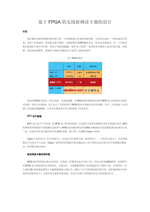
表1 RFID频率基本的RFID系统由三部分组成:天线或线圈、带RFID解码器的收发器和RFID电子标签(每个标签具有唯一的电子识别码)。
表1显示了常用的四个RFID频率及其潜在的应用领域。
其中,目前商业上应用最广的是超高频(UHF),它在供应链管理中有可能得到广泛的应用。
EPC电子标签EPC表示电子产品代码,是RFID电子标签的标准,它包括电子标签的数据内容和无线通信协议。
EPC 标准将条形码规范中的数据信息标准与ANSI或其他标准化组织(802.11b)制定的无线数据通信标准结合在一起。
目前应用在供应链管理中的EPC标准,属于第二代EPC Class-1标准。
Class-1标签在出厂时已经被写入,但也是可以现场下载。
通常情况下,一旦标签已被写入,内存即被锁定不可再次写入信息。
Class-1标签采用常规的分组传输协议—读卡器发送包含相关命令和数据的数据包,标签随后做出响应。
恶劣的读卡器应用环境RFID的应用环境可能非常恶劣。
信道的工作频率是免许可的工业、科技与医药(ISM)频带。
此频带中的RFID读卡器受到来自无绳电话、无线耳麦、无线数据网络以及其他临近读卡器的干扰。
必须将每一读卡器的RF接收器前端设计为能够抵御强干扰信号,避免产生可导致询问错误的失真。
接收器的噪声必须保持在较低的水平,以便具备足够的动态范围,从而以无错方式检测出低电平标签响应信号。
图1 使用的高性能RFID接收器架构图1中所示的读卡器RF射频收发器,是一个成熟的设计,能够在存在大量干扰源的恶劣环境中稳定地工作。
基于TRF7960的多协议射频读卡器设计
基于TRF7960的多协议射频读卡器设计
常国权;魏胜利;谢利江
【期刊名称】《单片机与嵌入式系统应用》
【年(卷),期】2010(000)007
【摘要】设计了一款基于TRF7960和STC11F32XE单片机的多协议自适应功能的射频读卡器,给出了射频读卡器的具体硬件和软件设计方案,并对设计中的难点作了分析.该读卡器支持多协议,支持防碰撞和多标签识别,功能完备,操作灵活,可以为各种RFID应用提供灵活有效的解决方案,同时也可为学习RFID技术的人员提供一个多协议、低价位的开发平台.
【总页数】4页(P39-41,65)
【作者】常国权;魏胜利;谢利江
【作者单位】安阳工学院,计算机科学与信息工程系,安阳,455000;安阳工学院,计算机科学与信息工程系,安阳,455000;安阳工学院,计算机科学与信息工程系,安
阳,455000
【正文语种】中文
【中图分类】TP368.2
【相关文献】
1.基于K60的多协议防碰撞RFID读卡器设计 [J], 孙奇燕;王宜怀;冯德旺;景林
2.基于MF-RC500的射频交通卡读卡器设计 [J], 孟凡宇
3.基于2.4G射频技术的远距离考勤读卡器的设计 [J], 彭赟;邓志良
4.门禁系统中多协议射频读卡器的设计 [J], 万方艳;董国勇;蔡阳;叶雁群;蔡嘉男;李航
5.基于EM4094模拟前端芯片的多协议读卡器设计 [J], 叶绍镇;赖晓铮;赖声礼因版权原因,仅展示原文概要,查看原文内容请购买。
Texas Instruments TI-RFid 高频读写器IC TRF7960 TRF7961产

RFID SystemsProduct Specifi cationsOverviewTexas Instruments Radio Frequency Identifi cation Systems is an industry leader in RFID technology, and the world’slargest integrated manufacturer of TI-RFid™ tags, TI-RFid smart labels, and TI-RFid reader systems. With more than1 billion RFID tags manufactured, TI-RFid technology is used in a broad range of RFID applications worldwide. TI isan active member of many standards bodies, including ISO, ISO/IEC, ECMA International, ETSI, and several nationalstandardization bodies working to drive the adoption of global standards for RFID technology. Array/rfi d Call 1-800-962-RFID(7343)* Dependent on the confi guration used, the RF regulation in country of use and the environmental conditionRFIDTag-it™ HF-I Standard Transponder Inlays/rfi dCall 1-800-962-RFID(7343)SPAT178A© 2010 Texas Instruments Incorporated Printed in U.S.A.Printed on recycled paperRFID010208AEurope, Middle East and Africa (EMEA)European Toll Free* 00800 275 83927International +49 (0) 8161 80 2121Russian Support +7 (495) 981 07 01*The European Toll Free number is not active in all countries. If you havetechnical difficulty calling the toll-free number please use the international numberFax: +49 (0) 8161 80 2045Business Hours (Central European Time)Monday – Wednesday 10:00 – 18:00Tuesday – Thursday 09:00 – 18:00Friday 09:00 – 16:00E-mail:******************Texas Instruments Deutschland GmbH RFID Systems Haggertystrasse 1D-85350 Freising GermanyImportant Notice: The products and services of Texas Instruments Incorporated and its subsidiaries described herein are sold subject to TI’s standard terms and conditions of sale. Customers are advised to obtain the most current and complete information about TI products and services before placing orders. TI assumes no liability for applications assistance, customer’s applications or product designs, software performance, or infringement of patents. The publication of information regarding any other company’s products or services does not constitute TI’s approval, warranty or endorsement thereof.The platform bar, TI-RFid and Tag-it are trademarks of Texas Instruments.All other trademarks are the property of their respective owners.TI RFID Worldwide Technical SupportInternetTI RFID Home Page/rfidProduct Information CentersUS and CanadaPhone 800-962-RF I D (7343)Fax: 214-567-7343Business Hours (Central Standard Time)Monday – Friday 8:00 am – 5:00 pm E-mail:******************Texas InstrumentsRadio Frequency Identification System 6550 Chase Oaks Blvd., MS 8470Plano, Texas 75023USAApplicationsPartner with TI, the technology leader in application-specifi c RFID solutions, for turnkey end-to-end formulas to employ RFID in specifi c tracking models such as recycling, waste management and high value asset tracking – to name a few. The integration of TI-RFid™ products into proven application models, in conjunction with third party Developers Network partners gives customers the ability to adapt an end-to-end RFID asset tracking solutions for their business, without costly mistakes or development time. TI’s RFID Application Solutions are state-of-the-art design and system models for unique vertical business needs that result in lower overall system cost and faster, more effi cient roll-outs. Learn more at /rfid-applicationsIMPORTANT NOTICETexas Instruments Incorporated and its subsidiaries(TI)reserve the right to make corrections,modifications,enhancements,improvements, and other changes to its products and services at any time and to discontinue any product or service without notice.Customers should obtain the latest relevant information before placing orders and should verify that such information is current and complete.All products are sold subject to TI’s terms and conditions of sale supplied at the time of order acknowledgment.TI warrants performance of its hardware products to the specifications applicable at the time of sale in accordance with TI’s standard warranty.Testing and other quality control techniques are used to the extent TI deems necessary to support this warranty.Except where mandated by government requirements,testing of all parameters of each product is not necessarily performed.TI assumes no liability for applications assistance or customer product design.Customers are responsible for their products and applications using TI components.To minimize the risks associated with customer products and applications,customers should provide adequate design and operating safeguards.TI does not warrant or represent that any license,either express or implied,is granted under any TI patent right,copyright,mask work right, or other TI intellectual property right relating to any combination,machine,or process in which TI products or services are rmation published by TI regarding third-party products or services does not constitute a license from TI to use such products or services or a warranty or endorsement e of such information may require a license from a third party under the patents or other intellectual property of the third party,or a license from TI under the patents or other intellectual property of TI.Reproduction of TI information in TI data books or data sheets is permissible only if reproduction is without alteration and is accompanied by all associated warranties,conditions,limitations,and notices.Reproduction of this information with alteration is an unfair and deceptive business practice.TI is not responsible or liable for such altered rmation of third parties may be subject to additional restrictions.Resale of TI products or services with statements different from or beyond the parameters stated by TI for that product or service voids all express and any implied warranties for the associated TI product or service and is an unfair and deceptive business practice.TI is not responsible or liable for any such statements.TI products are not authorized for use in safety-critical applications(such as life support)where a failure of the TI product would reasonably be expected to cause severe personal injury or death,unless officers of the parties have executed an agreement specifically governing such use.Buyers represent that they have all necessary expertise in the safety and regulatory ramifications of their applications,and acknowledge and agree that they are solely responsible for all legal,regulatory and safety-related requirements concerning their products and any use of TI products in such safety-critical applications,notwithstanding any applications-related information or support that may be provided by TI.Further,Buyers must fully indemnify TI and its representatives against any damages arising out of the use of TI products in such safety-critical applications.TI products are neither designed nor intended for use in military/aerospace applications or environments unless the TI products are specifically designated by TI as military-grade or"enhanced plastic."Only products designated by TI as military-grade meet military specifications.Buyers acknowledge and agree that any such use of TI products which TI has not designated as military-grade is solely at the Buyer's risk,and that they are solely responsible for compliance with all legal and regulatory requirements in connection with such use. TI products are neither designed nor intended for use in automotive applications or environments unless the specific TI products are designated by TI as compliant with ISO/TS16949requirements.Buyers acknowledge and agree that,if they use any non-designated products in automotive applications,TI will not be responsible for any failure to meet such requirements.Following are URLs where you can obtain information on other Texas Instruments products and application solutions:Products ApplicationsAmplifiers Audio /audioData Converters Automotive /automotiveDLP®Products Communications and /communicationsTelecomDSP Computers and /computersPeripheralsClocks and Timers /clocks Consumer Electronics /consumer-appsInterface Energy /energyLogic Industrial /industrialPower Mgmt Medical /medicalMicrocontrollers Security /securityRFID Space,Avionics&/space-avionics-defenseDefenseRF/IF and ZigBee®Solutions /lprf Video and Imaging /videoWireless /wireless-appsMailing Address:Texas Instruments,Post Office Box655303,Dallas,Texas75265Copyright©2010,Texas Instruments Incorporated。
RFID射频识别技术UID的获取
3.理解Ti_RF7960硬件连接原理框图
4.端口的检查
5.寻卡过程
6.读标签UID号、读/写/锁定数据块命令
7.串口助手的简单用法
8.上位机软件的使用
关键步骤:无线龙实验箱的驱动检查与安装更新、端口的检查、
关键操作:实验箱的连接、相应端口号的查看,协议设置,读卡/询卡过程。
2.需将TI TRF7960读卡器右下角的拨码开方拨向usb端,安装成功在设备描述中有一个串口端口,安装完成后在设备管理器中查看COM端口。
3.确保TI TRF7960RFID与电脑连接正常,打开上位机软件无线龙RFID选择可用COM端口连机
实
验
内
容
本次实验的主要内容包括:
1.对无线龙试验箱的认识和用法
总
结
9.在本次实验中,我掌握了无线龙上位机软件和串口助手工具的使用方法,并且理解Ti_RF7960硬件连接原理框图,读卡/询卡过的程。
4.询卡,当标签接收到inventory的命令,芯片将执行防冲撞序列。并执行操作:(1)选择询卡命令(2)选择设置协议(3)选择执行。此时无线龙会返回一个UID值。
5.设置标签标志位:双幅载波、高数据率,选择数据编码模式1 out of 4或者1 out 256。分别设置不同组合的参数,设置完成单击“设置协议”,主机会发送3条命令。其中在发送写寄存器命令时,将不同的设置写入到相应寄存器中
实
验
设
计
思
想
描
述
及
实
验
步
骤
实验设计思想:
实验通过上位机软件给无线龙试验箱开发系统发送指定的指令,由无线龙试验箱里的TI TRF7960读卡器进行读卡(ISO156963、1444标签),将读取到的数据通过USB数据线传送到上位机,并将结果通过仿真软件显示出来,以此就可以得到标签里的信息(UID号)。
UHF频段rfid读写器的电路设计
UHF频段rfid读写器的电路设计摘要:近年来,射频识别(rfid)系统已经在诸多领域得到了推广和运用。
为了满足社会对UHF频段rfid读写器的使用要求,对基于UHF频段的射频识别读写器的电路设计进行了研究。
关键词:UHF频段;rfid读写器;电路设计1读写器天线及匹配滤波电路设计读写器控制芯片采用TI公司的耐高温超低功耗单片机MSP430F2370,射频前端芯片采用TRF7970A。
TRF7970A芯片是TI公司推出的一款工作于13.56MHzNFC/RFID系统的集成式模拟前端(AFE)和多协议数据组帧器件,耐温可高达110℃,支持ISO/IEC14443-A/B、ISO/IEC15693以及Tag-it等协议,可完成硬件编码解码、调制解调、组帧分析等数字处理功能,避免软件部分在单片机中编写协议栈,降低了系统的复杂度。
TRF7970A芯片可以通过VDD_X由内置的辅助电源整流器向外部供电,并可以通过引脚SYS_CLK向外部提供时钟信号。
为减少读写器组件、降低功耗,设计时由射频前端芯片为提供工作电压和同步时钟频率,仅保留一个13.56MHz标准晶振。
单片机与射频前端芯片以并行方式通信。
射频前端芯片有三个射频收发相关引脚:片内主接收器引脚,片内辅助接收器引脚以及射频发送引脚。
接收时,控制系统会在片内主接受器引脚与片内辅助接收器引脚之间自动切换较大RSSI值的引脚作为主要接收端口。
接收端口阻抗为10kΩ,接收采用负载调制方式,耦合性功率能够较明显地体现在电压上,因此外围电路无需考虑匹配获取最大功率,只要通过分压获得信号电压,能够检测电压的差异即可。
发送端口工作在半功率工作时输出阻抗为8Ω,工作在全功率时输出阻抗为4Ω。
与接收端口不同,发送端口需要为了功率最大化而进行匹配[1]。
射频芯片端口与外接天线匹配方式一般分为两种:从两端往中间共同匹配至50Ω标准阻抗或者两端直接进行匹配,本文读写器采用前者匹配方式,即天线和TRF7970A的TX _OUT端口共同匹配至50Ω。
基于射频识别技术的射频卡读写器的设计

基于射频识别技术的射频卡读写器的设计射频识别(radiofrequencyidentification,RFID)技术是从20世纪90年代开始兴起的一项自动识别技术.它利用无线射频方式进行非接触双向通信,以达到识别目的并交换数据.其主要优点是环境适应性强,不受雪雨,冰雹,灰尘等的影响,且可穿透非金属物体进行识别,抗干扰能力强.关键字:射频识别射频卡读写器引言射频识别(radiofrequencyidentification,RFID)技术是从20世纪90年代开始兴起的一项自动识别技术.它利用无线射频方式进行非接触双向通信,以达到识别目的并交换数据.其主要优点是环境适应性强,不受雪雨,冰雹,灰尘等的影响,且可穿透非金属物体进行识别,抗干扰能力强.RFID技术已在世界各地得到广泛的应用,并在安全,金融,物流等领域发挥出巨大优势,以美国,日本和欧洲为首的发达国家对该技术的应用研究已达到相当高的水平,而我国则处于起步阶段,大多采用引进的技术成果,因而研究该技术已成为当今社会发展的必需.人们将振荡回路移人交变场附近时,能量便通过振荡回路的线圈感应出交变磁场能量.如果交变磁场的频率与振荡回路的谐振频率相同,振荡回路就激发了谐振振荡.振荡线圈上的振荡过程,可以根据交变磁场中振荡线圈的短时电压变化或电流变化得到.这种线圈电流的短时上升(或线圈电压下降)被称作降落(Dip).Dip的相对强度取决于两个线圈的距离和其相对运动的速度.为了保证可靠的识别射频卡振荡回路,需要获得一个尽可能明显的Dip.但我们不能对振荡器进入磁场的速度施加特别的限制,只能考虑以无限小的速度接近振荡回路时所产生的一种无限小的Dip.所以,我们使产生磁场的磁场频率不是恒定的,而是“扫频”的.振荡器频率不断扫过最大和最小频率之间的范围,如果扫频的振荡频率正好命中了在射频卡里振荡回路的谐振频率,其振荡回路就开始起振,并由此在振荡器线圈的电流中产生一个明显的Dip.由电感耦合原理,再通过数据载波调制和解调技术,由振荡回路组成的射频系统和由扫频回路组成的读写系统就实现了通信.我们利用RFID技术,通过单片机控制射频模块,利用天线发出适合射频卡的共振磁场,使其可以有效的与射频卡实现数据通信,完成射频卡的识别和卡内数额的增加与减少.1材料和方法1.1材料1.1.1射频部分美国德州仪器公司(TI)在1991年创立TIRIS。
射频识别(RFID)节点技术设计及应用开发

射频识别(RFID)节点技术设计及应用开发摘要:本文以STC11F32XE单片机为核心,设计了一个无线射频识别的读卡器。
本设计中,印制在PCB板上的磁场耦合天线通过磁场感应收集到IC卡上的数据信号(这里是模拟信号),然后天线将收集到的数据信号传回给TRF7960无线射频识别芯片,TRF7960再将此信号进行数据预处理,即模拟信号的数字化,然后将此数字化后的信号通过串口通信的方式传送给STC11F32XE单片机,STC11F32XE单片机会驱动12864液晶,最终将IC卡上的数据信息显示在12864液晶屏上。
文章详细介绍了TRF7960芯片的工作原理和读卡器具体的硬件与软件设计方案、思路及实现方法。
设计中,功能实现的步骤包括寻卡、读卡和中断等,该读卡器可实现对ISO14443A类型卡的识别功能。
关键词:射频识别;非触碰式IC卡;读卡器;TRF7960;ISO14443ARadio Frequency Identification (RFID) Technology Node Design and Application DevelopmentAbstract: This paper STC11F32XE microcontroller as the core, a radio frequency identification of the card reader is designed. The design, magnetic field coupling antenna is printed on PCB through the magnetic field induction to collect data on the IC card signal (analog signal here), then the data signal will be collected by the antenna back to the radio frequency identification chip TRF7960, this data signal again be pretreatmented by TRF7960, namely of the analog signal digital, then will the digital signal through serial communication transmitted to the way STC11F32XE microcontroller,12864 LCD Wwill be drived by STC11F32XE microcontroller, will eventually IC card of data on information displayed in 12864 on the LCD panel.The TRF7960 chip works, reader specific hardware and software design solutions, ideas and implementation are detailed in this article. Design features to achieve the steps include seeking cards, readers and interruption, the reader can achieve the type of card ISO14443A recognition.Keywords: Radio frequency identification; Non-touch-type IC card; Reader; TRF7960; ISO14443A目录第1章绪论 (4)1.1射频识别技术的研究和意义 (4)1.2国内外研究现状和发展 (4)1.3本论文研究内容 (5)第2章无线射频识别系统的基本组成及工作原理 (6)2.1RFID系统基本组成 (6)2.2无源射频识别技术的基本工作原理 (6)2.3无线射频识别工作的物理学原理 (7)2.4读写器 (8)2.4.1 读写器的作用及分类 (8)2.4.2 读写器的基本构成 (8)2.5读写器天线 (8)2.5.1 读写器天线简介 (8)2.5.2 读写器天线设计技术 (9)2.5.3 读写器天线制造技术 (9)2.6射频电子标签 (10)2.6.1射频电子标签概述 (10)2.6.2 无源电子标签的构成和工作原理 (11)2.6.3 RFID标签天线设计 (12)2.7客户机、服务器和通信网络 (13)第3章系统方案及其基本架构 (14)3.1方案选择 (14)3.2元器件选择及简要介绍 (14)3.2.1 TRF7960芯片 (14)3.2.2 STC11F32XE芯片 (16)3.2.3 PL2303芯片介绍 (17)3.2.4 128X64LCD液晶显示器 (20)3.2.5 无源射频卡 (21)第4章系统硬件设计 (23)4.1设计思路 (23)4.2本设计工作原理 (23)4.3各模块设计原理图 (23)4.3.1 TRF7960设计原理图及PCB图 (23)4.3.2 STC11F32XE 单片机设计原理图 (24)4.3.3 PL2303设计原理图 (25)4.3.4 LCD液晶设计原理图 (26)4.3.5 天线网络设计 (27)4.4硬件PCB设计及注意事项 (28)第5章系统软件设计 (29)5.1各应用子程序介绍 (29)5.1.1 读写子程序 (29)5.1.2 初始化TRF7960子程序 (29)5.1.3 获取ID号子程序 (29)5.1.4 中断处理子程序 (31)5.1.5 LCD液晶显示子程序 (33)5.2软件设计总体介绍 (35)第6章系统硬件与软件的调试 (36)6.1系统硬件的调试 (36)6.1.1 调试思路及用到的工具 (36)6.1.2 调试过程中遇到的问题及解决方法 (36)6.2系统软件的调试 (37)6.2.1 子程序编译 (37)6.2.2 下载调试 (39)6.3软件编写和调试经验总结 (42)第7章结论 (44)致谢 (45)参考文献 (46)附录各硬件效果图 (47)第1章绪论1.1 射频识别技术的研究和意义RFID(Radio Frequency Identification)无线射频识别技术是20世纪90年代开始兴起的一种自动识别技术[1]。
基于ARM的多标签多协议RFID读写器设计
基于ARM的多标签多协议RFID读写器设计朱强;曾碧【摘要】This paper introduces the design principles and methods of multi-label multi-protocol RFID reader on the embedded platform using ARM9 as the core processor, and the specific hardware and software design and system implementation. TI's 13.56 MHz chip TRF7960 is used as the RF module and communicates to RF front-end chip through MSP430F2370, which improves the reader perform- ance and achieves multi-tag anti-collision identification with the binary search algorithm. In actual operation, the system is stable, relia- ble and easy to operate.%介绍了以ARM9为核心处理器的嵌入式平台的多标签多协议RFID读写器的设计原理与方法,给出了系统具体的硬件和软件设计方案和实现方法。
采用TI公司的13.56MHz频段下的芯片TRF7960作为射频模块,通过MSP430F2370与射频前端芯片通信,有效地提高读写器的性能,并在软件中结合二进制搜索算法实现多标签防碰撞识别。
该读写器经过实际运行,具有稳定可靠、操作简便等特点。
【期刊名称】《单片机与嵌入式系统应用》【年(卷),期】2011(011)012【总页数】4页(P33-35,39)【关键词】多标签;多协议;TRF7960;RFID;读写器【作者】朱强;曾碧【作者单位】广东工业大学,广州510006;广东工业大学,广州510006【正文语种】中文【中图分类】TP368.2引言随着现代信息技术和超大规模集成电路的发展,RFⅠD技术在服务领域、货物销售与后勤分配、商业部门、生产企业和材料流通领域得到了越来越广泛的应用。
基于TRF7970A的NFC模块设计
Ab s t r a c t :I n t h i s p a p e r ,i n t r o d u c e s t r u c t u r e a n d w o r k i n g c h a r a c t e r i s t i c o f T RF 7 9 7 0 A, w h i c h s u p p o r t NF C s t a n d a r d NF CI P 一1
Net wor k a n d Comm un i c a t i on
基于 T R F 7 9 7 0 汉工 程 大 学 电 气信 息 学 院 , 湖北 武汉 4 3 0 0 7 3 )
摘 要 : 介 绍 了 T I 公 司 最 新 推 出 的 多协 议 完 全 集 成 l 3 . 5 6 MH z收 发 一 体 芯 片 T R F 7 9 7 0 A 的 结 构 特性和工作特点 . 支持 近 场 通 信 ( N F C) 标准 N F C I P —l ( I S O/ I E C 1 8 0 9 2 ) 和 N F C I P 一 2 ( I S O / I E C 2 1 4 8 1 ) , 在
1 3 . 5 6 MH z收 发 一 体 芯 片 T R F 7 9 7 0 A 的 基 础 上 ,设 计 了
具 有 主 动 模 式 和 被 动 模 式 的 NF C模 块 。
电子 海报 等 不 同的领 域 。
关 键 词 :T R F 7 9 7 0 A: N F C: 微 控 制 器
中 图 分 类 号 :T N 9 2 9 文 献 标 识 码 :A 文 章 编 号 :1 6 7 4 — 7 7 2 0 ( 2 0 1 3) 1 7 — 0 0 4 4 — 0 5
- 1、下载文档前请自行甄别文档内容的完整性,平台不提供额外的编辑、内容补充、找答案等附加服务。
- 2、"仅部分预览"的文档,不可在线预览部分如存在完整性等问题,可反馈申请退款(可完整预览的文档不适用该条件!)。
- 3、如文档侵犯您的权益,请联系客服反馈,我们会尽快为您处理(人工客服工作时间:9:00-18:30)。
①尽量让滤波电容靠近芯片,特别是10 nF的电容,这样对高频信号进行有效的滤波;
②尽量减少布线地的回路,所以要求接地的过孔尽量靠近元器件或者IC的接地端;
③2个电感的放置应该成90°的方向,这样主要减少2个电感之间的耦合;
④数字地和模拟地最好是在不同的地方,最好通过磁珠或电感进行连接;
设计好硬件平台之后,就需要设计系统的软件模块。在软件模块设计中STCllF32XE单片机和TRF7960之间的模拟通信是最关键的一步,因为只有打通了底层通信的关键环节,STCllF32XE才能进一步通过控制TRF7960实现读/写卡的基本操作。为了实现这一步,首先要弄清楚 TRF7960的读写时序。
TRF7960是TI(德州仪器)公司推出的高频(13.56MHz)多标准射频识别(RFID)阅读器IC产品系列之一。TRF7960采用超小32-pin QFN的高级封装设计,支持ISO/IEC 14443A/B、ISO/IEC 15693、ISO/IEC 18000-3以及TI公司的非接触支付商务与Tag-It应答器产品系列。采用TRF7960的读卡器为微控制器提供了内部时钟,只需1个13.56 MHz的晶振就能工作,而不需要2个标准晶体,从而有助于降低终端读卡器产品的总物料单成本。由于组件很少,读卡器IC耗电、占用的空间也很少,因此可以解决敏感度和噪声衰减问题。其他集成功能还包括故障检查、数据格式化、成帧以及适合多读卡器环境的防碰撞支持等。TRF7960与微控制器之间通信可以使用8位并行或者串行(SPI)的灵活的通信方式。该芯片还具有宽泛的操作电压(2.7~5.5 V)。TRF7960非常适用于安全访问控制、产品认证以及非接触支付系统等应用。
打通了底层通信的关键环节之后,就可以一步一步地编写调试各个软件模块。图3是读卡器多协议自适应功能软件模块流程。
3 结论 本文采用宏晶公司的高速、低价位单片机和TI公司的TRF7960多协议读卡芯片以及相应的外围电路设计出了非接触式的射频读卡器,设计按照ISO/IEC 14443A/B和ISO/IEC 15693多协议标准,完成了系统的硬件电路搭建和系统软件的设计工作。经实际使用证明,该读卡器工作稳定,抗干扰能力强,性价比高,操作灵活、方便,产品具有很强的的市场竞争力,投入使用将会产生较好的经济效益。
⑤保证芯片中间的部分足够接地,可以在电路板上打9个孔,让芯片充分接地和散热;
⑥布线时尽量减少辅线的长度,特别是射频前端,让元器件保持紧凑、射频输出前端最好保持畅通的输出;
⑦在电路中最好加一些测试点,方便调节硬件电路;
⑧尽量避免在射频线路中通过数字信号。
2 读卡器的软件设计
显示屏采用的是基于ST7565S控制器的图形点阵LCD模块,分辨率为128×64,支持串行接口,不带汉字库。为了能使该读卡器可以应用在诸如图书馆图书管理方面和其他需要需要汉字显示的场合,采用华邦公司生产的串行存储器W25X80,自行设计了GB2312汉字库和其他图片库。串行Flash存储器以其体积小、密度高、功耗低、价位低、操作简单而备受青睐,Winbond公司生产的Flash存储器W25X80为8 Mb串行Fla-sh,大小为1 MB,分为4096页,每页为256字节的存储单元,且带有256个字节的缓冲区,SPI的接口方式。使用Flash自行设计汉字库不仅操作十分简单,并且可以灵活地适用于多个设计方案。
1 读卡器的硬件设计
STCllF32XE单片机是宏晶科技公司设计生产的单时钟/机器周期(IT)的单片机,是高速、低功耗、超强抗干扰的新一代8051单片机,指令代码完全兼容传统8051,但速度快8~12倍。内部集成高可靠复位电路,可用在高速通信、智能控制、强干扰等场合。STCllF32XE内部有32 KB的Flash,29 KB的EEPROM和1 280字节的SRAM。本文采用的STCllF32XE是LQFP-44引脚,除了EA、ALE、PSEN和RST引脚可以定义为通用I/O外,还多了1 个P4口。编程支持ISP下载功能,使用起来比较方便。
为了使用STCllF32XE单片机内部1 KB的扩展SRAM,此处采用的是8位并行模拟总线接口方式,用单片机的P1口和TRF7960的DO~D7相连,用P2.6、P2.7、P3.2作为控制线分别和TRF7960的DATA CLK、EN、IRQ引脚相连。需要注意,为了使TRF7960通信接口支持5 V的逻辑电平,应该把TRF7960的VDD_I/O引脚接5 V电压。采用模拟总线方式是一种通用的方法,特别是对于不支持总线扩展的单片机更为重要。该设计中使用模拟总线的方式可防止TRF7960和单片机内部的 SRAM发生总线冲突。图1是读卡器的系统硬件原理图。
PL2303是Prolific:公司生产的USB总线转接芯片,可以实现USB转串口,用于为计算机扩展异步串行口,或者将普通的串口设备直接升级到USB总线。PL2303完全兼容USBl.1、USB2.0;3~5 V调节输出,可以满足不同的电压输出接口;全双工发送和接收(RXD、TXD);MODEM控制线(RTS、CTS、DTR、DSR、DCD和 RI);5、6、7或8位数据格式;奇偶校验或无校验;1位、1位半或2位停止位;可编程的波特率75 b/s~6 Mb/s等。因此,PL2303是移动系统和嵌入式系统的理想选择,其小封装能够嵌入任何连接件和手持设备。PL2303在工作模式和休眠模式都具有很低的功耗,非常适合总线供电场合使用。USB芯片使得该读卡器省去了串口和电源供电端口,可以通过该USB接口和PC管理软件通信。
起始条件是CLK为高,然后先发送8位地址,再发送数据。发送格式在时钟的下降沿进行发送,当CLK为高时,在A/D有1个下降沿,表示结束。根据该时序图可以写出STCllF32XE单片机从TRF7960读/写1个字节的C语言实现代码:
STCllF32XE单片机主要就是通过调用这两个最基本的函数来实现对TRF7960进行复杂的读/写控制的。采用模拟总线通信方式的最大好处就是用C语言写的代码很容易移植到不支持总线扩展的各种单片机上,增加了软件模块的可复用性和可移植性。
基于
无线射频识别技术(RFID)作为一项先进的自动识别和数据采集技术,已经广泛应用到生产制造、物流管理、公共安全等各个领域,并带动了读写机具和各类应用产品及系统的开发、生产和推广应用。目前,在我国应用于13.56 MHz的无线射频识别技术领域主要有2个ISO标准,一个是IS014443,另一个是ISO15693。ISO14443定义了TYPE A、TYPE B两种类型协议,通信速率为106 kb/s,它们的区别主要在于载波的调制深度及位的编码方式。ISO15693读写距离较远,而ISO14443读写距离稍近,但后者应用较广泛。这三种协议的卡在各个领域都有着比较广泛的应用,而国内现有的13.56 MHz的射频读卡器,一般仅支持一种协议,且功能较为单一。基于这种现状,本文提出了基于TI公司的TRF7960射频芯片和宏晶公司的 STCllF32XE高速单片机来设计多协议射频读卡器的设计方案。在该读卡器上扩展了点阵图形液晶LCD和串行存储器W25X80以及USB芯片PL2303等外围设备。LCD可以显示各种图形和汉字,串行存储器用来存储点阵字库、图形库等,USB芯片使得该读卡器省去了串口和电源供电端口,可以通过该USB接口和PC管理软件通信。该读卡器使用方便,简单,成本低,电路运行稳定,可以应用到各种场合。
