电主轴说明书
OLISPEED电主轴说明书

OLISPEED电主轴说明书一、产品概述OLISPEED电主轴是一种高精度、高效率的电动驱动装置,可广泛应用于机床、自动化设备、机器人等领域,以提供高速、精密的转动运动。
本说明书将详细介绍OLISPEED电主轴的性能特点、使用方法以及维护保养等方面的内容。
二、性能特点1.高效率:OLISPEED电主轴采用先进的电动驱动技术,能够在保持高速运转时保持较高的能量转换效率,极大地提高了设备的生产效率。
2.高精度:OLISPEED电主轴采用精密的轴承和优化设计的传动结构,可实现高精度的转动运动,满足客户对产品的精度要求。
3.高刚性:OLISPEED电主轴采用高强度材质制造,具有较高的刚性,能够在高速运转时抵抗外界的振动和冲击,提供更加稳定的工作环境。
4.多功能:OLISPEED电主轴支持多种控制方式,可与各种控制系统无缝集成,满足不同应用场景下的需求。
三、使用方法1.安装:在安装OLISPEED电主轴时,请务必遵循安装说明书中的安装要求,确保正确安装,以保证设备的正常运行和安全性。
2.连接电源:将OLISPEED电主轴正确连接到电源,并按照操作面板上的指示进行操作,以启动电主轴。
3.控制方式选择:根据具体应用需求,选择适合的控制模式,可以通过设备上的操作键或者与控制系统相连的接口进行设置。
4.参数调整:根据具体工作要求,调整OLISPEED电主轴的参数,包括速度、加减速度、转子惯量等,以达到最佳工作效果。
5.维护保养:定期检查OLISPEED电主轴的运行状态和保养维护,包括轴承润滑、冷却系统的清洁和散热器的清理等,确保设备的长期稳定运行。
四、维护保养1.轴承润滑:定期检查轴承的润滑情况,根据运行时间和工况要求进行轴承润滑,可采用润滑脂或者润滑油进行润滑。
2.冷却系统清洁:定期检查冷却系统,清洗冷却器和冷却管路,以确保冷却效果和散热性能。
3.散热器清理:定期清理散热器上的灰尘和污垢,保持散热器的散热效果,以确保设备的长期稳定运行。
广州昊志车床电主轴手册

2016年第1版 DGZC-20008800038011104533G1A2-5≦0.003≦0.003≧85%油脂 Grease油脂 Grease 版权所有,翻录必究!微信二维码DGZC-2400660003802240 14G1 A2-6 ≦0.003≦0.003 ≧85%车床主轴是昊志机电专门针对金属等材料高精密、高转速、高效能加工精心设计的系列产品。
该系列产品汇聚了昊志机电多年的主轴设计与制造经验,对设备及切削加工工艺的深刻理解、全球主轴技术领域最先进技术的把握,在悉心听取客户需求的基础上精心研制而成。
昊志机电车床主轴系列产品得到了国内外客户的广泛关注和使用,已成为该领域设备厂家及终端生产厂家的首选产品和行业标杆产品,并以最齐全的产品线满足众多客户的多样性需求,产品技术领先,性价比优越。
昊志机电车床主轴系列产品主要运用于车床车削等加工。
高精度:高刚性:高效率:多样性:稳定可靠:国际顶级制造设备加工的零部件,并采用国际知名品牌的主轴轴承、结合多年积累优化的先进装配体系,使主轴具有无与伦比的回转精度,为高精加工提供保障。
采用大轴径滚珠滚子轴承,轴承布置和预紧经最优化设计,确保主轴刚性最佳。
车床电主轴内置永磁同步电机,在低速大扭矩,高速高精度,快速启停,精准控制,超低振动方面尤显突出。
主轴可配置气幕密封、设计不同刹车结构,应用不同驱动形式,满足不同需求。
主轴采用免维护润滑结构设计,运转温升低,长寿命周期免维护运行。
创造金色品牌 引领世界潮流创造金色品牌 引领世界潮流创造金色品牌 引领世界潮流昊志机电是一家专业从事高精密电主轴及其零配件的研发设计、生产制造、销售与维修服务的环保型高新技术、创业板上市企业,股票代码300503。
昊志机电“以中高端电主轴产品为核心、以电主轴精密零配件制造为支撑、以配套维修服务为特色”,通过坚持不懈的技术攻关和持之以恒的品质管理,构建了电主轴“整机—配件—服务”紧密结合的完整业务链。
(主轴操作说明书)LM600HD_Spindle_30000rpm_cn

第1页Franz Kessler GmbH 电主轴操作说明第2页目录EC制造商声明 (3)注意 (4)预期使用 (4)安全说明 (5)安全运输 (5)安全装配和维修 (6)安全检查 (6)永磁性转子的安全处理 (6)安全操作 (7)储存 (8)装配 (9)准备工作 (9)机械连接 (9)连接电路 (9)连接传感器 (9)电动机绕组温度传感器(S7) (9)速度和位置测量传感器(S5/S6) (10)刀具夹紧监测(S1-S3) (11)主轴与电机冷却 (12)冷却润滑回路 (13)连接 (13)时间顺序 (14)松夹钳单元的液压连接 (15)气动连接 (16)油气润滑 (17)投入运行 (18)退役和拆卸 (19)重要操作说明 (20)维护 (21)主轴刀具 (21)旋转传动单元 (21)刀具夹紧系统 (23)更换零件 (24)更换夹紧装置 (24)更换旋转传动单元 (26)更换渐近开关 (27)备件 (28)故障表 (28)故障检查表 (30)第3页EC制造商声明产品名称:交流电主轴类型: SMS090.32.4.FOS对上述提及的产品,我们作为制造商确认符合以下标准:• EN 60 034-1 ,评级• EN 60 034-5,各类保护• EN 60 034-6 ,冷却的方式• EN 60 034-9 ,噪声限值• EN 602041,机床安全上述产品是组件不能独立投入运行,只能被安装在预定的机床或工厂(最终产品)才能运行。
包括上述产品的最终产品还必须符合EC发布的声明标准。
在调试终端产品前必须检查它是否符合指令98/37/ECE.herwanger(经理)Franz Kessler GmbHFranz-Kessler-Straße 2D – 88 422 Bad Buchau (Germany)第4页注意在应用电主轴之前,必须仔细阅读该文件。
通过了解这些作业的指示,才能避免主轴故障和确保无故障工作。
电主轴手册 Z45-D160.02 S5A2说明书

手册Z45-D160.02 S5A2高频主轴气动直接换刀电主轴的标记系列号额定转速因为本公司的电主轴始终保持最新技术研发水平,所以我们保留更改和与本说明书中的实施方案相比的技术改进和不同内容。
本手册文字说明经过极为认真地编写。
但是错误和疏漏在所难免,对于因此而引起的后果,Alfred Jäger GmbH概不承担法律责任及任何其它责任。
未经 Alfred Jäger GmbH 明确的书面同意,不得翻译和复制(即使是节选)。
目录:原厂手册的翻译文本1初步信息 5 1.1手册用途 (5)1.2符号说明 (5)2运输和包装 6 2.1电主轴的供货范围 (6)2.1.1维修工具 (6)2.1.2可选配件 (6)2.1.3随产品附带的技术资料 (7)2.2电主轴的包装 (7)3按规程使用 8 3.1允许的加工类型 (8)3.2允许材料 (8)4安全注意事项 9 4.1工作要具备安全意识 (10)4.2电主轴的停止运转 (11)4.3安装维修 (11)4.4改装维修 (11)4.5不正确的操作方法 (11)5技术说明 12 5.1电主轴的接口 (12)5.2电气连接 (12)5.3冷却 (13)5.3.1通过电主轴托架冷却 (13)5.4密封空气 (13)5.5气动刀具更换 (13)6技术参数 14 6.1尺寸 (15)6.2技术数据页 (KL2006 , 交流电机) (16)6.2.1功率图 (17)6.3电路图 (18)6.4电机保护 PTC 100° C (19)6.5转速传感器(数字磁敏电阻) (20)6.6ESD 保护 (20)6.7空气传播听觉范围内的声音 (21)7操作地点 228安装 23 8.1安装电主轴 (23)8.2介质引线直径 (23)8.3压缩空气 (24)8.3.1气体纯度等级 (ISO 8573-1) (24)8.3.2调节密封空气 (24)8.3.3调节值 (25)9调试 26 9.1进料示意图 (26)9.2每天启动 (27)9.3停止信息 (27)9.4存放之后启动 (27)10刀具更换 28 10.1顺时针旋转 (28)10.2气动直接换刀 (28)10.2.1更换夹头 (29)10.3刀具更换站(可选附件) (30)10.3.1气动直接换刀 (30)10.3.2安装更换站 (30)10.3.3维修 (30)11高速加工刀具 31 11.1折断的刀具 (31)12维修 32 12.1球轴承 (32)12.2每日清洁 (32)12.2.1开始工作前 (32)12.2.2每次刀具更换时 (32)12.2.3每次更换夹具时 (32)12.3存放时 (33)12.4月维修 (33)12.5在长期存放条件下 (33)12.6最长存放期限 (33)13拆除 34 13.1废物处理及环境保护 (34)14服务和维修 35 14.1特约维修站 (35)14.2工作故障 (36)15安装声明 39目录:初步信息1初步信息高速电主轴(电主轴)是适用于高速加工的高质量精密刀具。
CyTec电主轴配置说明
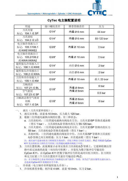
CyTec电主轴配置说明一、液压(刀具夹紧和放松):1. 液压站参数:流量6-10 l/min,压力最大120 bar。
2. 根据三位四通电磁换向阀的位置,有三种状态:a. 刀具放松时:三位四通电磁换向阀处在左位,刀具夹紧/SP管路直通油箱(背压1 bar),刀具放松/LO管路内的压力55-120 bar;b. 刀具夹紧时:三位四通电磁换向阀处在右位,刀具夹紧/SP管路内的压力55 bar,刀具放松/LO管路直通油箱(背压1 bar);c. 其他时候:三位四通电磁换向阀处在中位,刀具夹紧/SP管路和刀具放松/LO管路之间互相联通,压力1 bar,并直通油箱(背压1 bar)。
注:液压油只是驱动松拉刀机构发生的动作,在松刀和拉刀动作完成后,PLC须根据CyCon K11发出的松拉刀到位信号控制三位四通电磁换向阀处于中位。
3. 刀具位置检测:流量测量计必须安装在刀具放松/LÖ管路上,它能够检测出管路中流过油液的流量(双向均可检测),并装化为数字脉冲信号输送给CyCon K11;由CyCon K11把数字脉冲信号转化成对应松刀到位、拉刀到位和无刀拉紧三个刀具位置的开关量信号输送给PLC。
注:在主轴使用之前必须对松拉刀油路进行放气操作。
否则,因为空气的压缩性比液压油大,会造成CyCon K11检测的信号不准。
二、冷却液(电主轴冷却和旋转接头冷却):1. 冷却机推荐参数:制冷量4 kW,流量10 l/min,压力2 bar。
2. 冷却机必须是室温同调型的,温度控制精度±1 ︒C;使用时温度设定在室温±2~±3 ︒C。
3. 冷却液为乙二醇水溶液(浓度比例为20%);水硬度比较高的地区必须使用纯净水,乙二醇可以使用壳牌/Shell防冻液来代替。
4. 旋转接头冷却液入口/KWE管路和旋转接头冷却液出口/KWA管路,用于冷却旋转接头端部的密封陶瓷片。
在选用刀具中心冷却选项(CTS)时,这两条管路均通入冷却水,并由刀具中心喷出。
电主轴参数
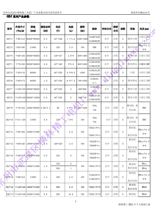
GDJ系列产品参数:2、安装前首先用手转动电主轴轴头,应手感灵活,无阻滞现象。
3、用500V的摇表检查定子绝缘电阻不低于100MΩ。
4、将以上检验符合要求的电主轴装入机座内,电主轴外壳以机座安装孔的配合为滑动配合。
电主轴严禁装夹在前、后轴承部位,以防轴承室变形,卡住轴承造成轴承提早损坏。
夹紧力不宜过大,电主轴装入机座内不得松动。
二、正确使用1、按要求连接电主轴进出水管接头,检查连接处是否漏水和通畅。
水冷电主轴的冷却系统系统应于机床的总开关连接;开机后至停机的中间,冷却系统系统应连续工作;冷却液水量按2.5升/千瓦·分钟计算,冷却液流量按3~6升/分钟,小的电主轴取小值,大的电主轴取大值;冷却液要求使用单独水箱,冷却液要求每月定期更换;冷却液的温度应低于环境温度3~5℃为宜,最好控制在25℃左右。
2、选择变频器应与电主轴的电压、功率、频率相匹配来配套使用。
设置变频器首先设置变频器的基准频率,变频器的基准频率按电主轴的最高频率设置。
变频器的最高频率、转折频率和对应的电压按电主轴的频压曲线对应设置;变频器的电流按电主轴的额定电流设置;载波频率按电主轴的功率大小设置,小于10kw电主轴按8kHz设置,大于10kw电主轴按5kHz设置;增、减速时间按10s左右设置,如遇到起动电流超过额定电流而保护时应延长增、减速时间。
增、减速时间过短易造成前螺母松动。
3、将变频器与电主轴三相电源连接,其中变频器的三相电源线应焊接在插头1(U1)、2(V1)、3(W1)脚上,4脚为地线。
然后变频器与外接电源连接。
接通电源后变频器点动,观察电主轴的旋转方向是否与电主轴指示方向一致,如旋转方向不一致应立即关机改正,电主轴严禁在错误的旋转方向上运转。
电主轴与变频器连线不宜超过25m。
4、电主轴在安装刀具时,应清除干净轴头锥孔及弹簧夹头表面的污垢,以免降低精度。
装夹、拆卸刀具时应使用专用工具。
注意装夹、拆卸时禁止用力过猛。
GMN电主轴使用说明书_手动换刀型_cn
continue
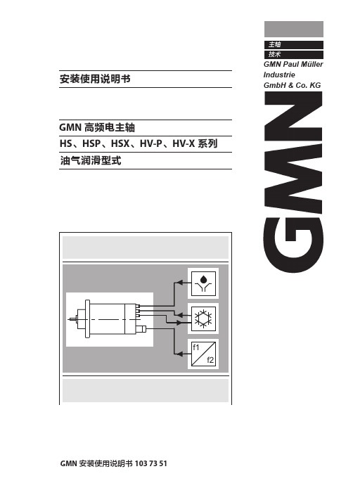
GMN 安装使用说明书 103 73 51
主轴 技术
安装使用说明书
GMN 高频电主轴 HS、HSP、HSX、HV-P、HV-X 系列 油气润滑型式
B B
GMN 安装使用说明书 103 73 51
前言
GMN 高频主轴是高精度的精密器械 其性能和使用寿命取决于正确的操作和使用 因此,在使用前所有相关人员(操作者和维护人员)都必须仔细阅读、理解并遵 守本主轴安装使用说明书。
2
GMN 安装使用说明书 103 73 51
SP O3 3.1 3.2 4 4.1 4.2 4.3
基本信息 ................................................................................................................ 5 安全说明................................................................................................................ 7 主轴描述 ................................................................................................................ 9 主轴配备.............................................................................................................................................. 9 主轴运行的供应组件 ...................................................................................................................10 主轴安装 .............................................................................................................. 11 主轴的型号名称 .............................................................................................................................11 主轴的储存和运输 ........................................................................................................................12 主轴夹持............................................................................................................................................13
电主轴说明书模板

YG62-60L使用说明书目录一、产品概述 (1)▷产品简介 (1)▷产品用途 (1)二、主轴外形图 (2)三、技术参数表 (3)四、电机特性曲线 (4)五、主轴安装说明 (5)▷测温传感器及其阻温特性对照表 (6)▷循环冷却系统说明 (8)▷换刀装置的控制 (8)▷空气密封及主轴吹尘的控制 (8)▷压缩空气气体质量要求 (9)▷跑合程序说明 (9)▷主轴驱动要求 (9)▷主轴安装要求 (10)六、使用注意事项 (11)▷主轴装机过程注意事项 (11)▷启动注意事项 (11)▷维护和保养注意事项 (12)一、产品概述▷产品简介1.本主轴为电机内装式主轴, 内置三相交流异步感应电机, 有变频器进行无级变速控制。
由于本主轴具有结构紧凑、重量轻、惯性小、振动小、噪声低等特点因此能够实现高转速, 高精度及高运转稳定性。
2.本主轴轴承采用油脂润滑陶瓷复合球轴承, 可在轴承的使用寿命周期内实现终生润滑3.本主轴使用强制冷却的方式对电机、前后轴承进行冷却。
冷却液流经主轴机体合理布置的循环水道带走主轴高速旋转产生的热量, 达到热平衡, 使电主轴的温度恒定在一定值内。
外置的冷却装置: 保持冷却液的温度恒定。
4.本主轴内置PTC130测温传感器( 其技术参数详见本说明书其它章节) , 如需进行对电机做温度保护时能够读取。
5.刀具加紧方式: 本主轴内置自动换刀装置, 刀柄形式为直接换刀, 标配为ф6, 可选配ф4, ф3.175.▷产品用途本产品为基础主轴, 主要用于雕铣机或加工中心进行有色金属、黑色金属、玻璃、石墨等材料的加工。
二、主轴外形图三、技术参数表20 电机绕组耐压试验1500V/min四、电机特性曲线▷功率、扭矩-转速曲线▷电压-频率曲线五、主轴安装说明▷测温传感器技术参数1.传感器类型: PTC(正温度系数), 常温阻值R25≤255Ω2.开关特性: 温控点Tk=130℃,Tk-5≤1650Ω,Tk+5≧4200Ω偏差△T=±5℃, Tk重复性△T=±0.5℃4.热动作时间: ≤2S5.最大工作电压30V(DC),绝缘强度2.5KW6.最高允许存放温度180℃, 最低允许存放温度-25℃▷循环冷却系统说明◆水冷要求: 推荐使用蒸馏水, 同时推荐使用费诺克斯( Femox) 保护剂F1(使用配比1:200).冷却液的温度建议为24℃-28℃, 当不能达到时, 应该与环境温度基本一致, 进水管、回水管温差不超过5℃◆一般在冷却系统的回水管中设置流量开关, 以便控制冷却液的流量, 确保主轴冷却液的正常供给。
kessler电主轴说明书
Assembly InstructionsGrinding spindleModel E13811BArticle number 000.633.533Serial number ______________Date of delivery ______________Original Assembly Instructions - GermanAll other languages are a translation of the original.Franz Kessler GmbHFranz-Kessler-Strasse 2 • 88 422 Bad BuchauTelephone: +49 (0)7582 / 809-0 • Fax: +49 (0)7582 / 809-170e-mail: franz-kessler@franz-kessler.de • web: http://www.franz-kessler.deOI 000.654.990_EN Created: 10/2010ContentsDeclaration of incorporation (5)1. About these assembly instructions (6)Scope of delivery (6)2. For your safety (7)General (7)Designated use (7)Non-authorised usage (7)Product identification (7)Important operating instructions (7)Operator's responsibility (8)Qualified technical staff (9)Work on the electrical system (9)Work on the hydraulic system (9)Personal protective equipment (9)Information about warning notices (10)Warning symbols (10)Warning levels (10)Damage to property (11)Other symbols used (11)Safety instructions (12)Danger due to electrical voltage (12)Danger due to hydraulic fluid (12)Danger due to compressed air (13)Danger of environmental pollution (13)3. Transport (14)4. Storage (15)5. Assembly (16)General informations (16)Installation position (16)Standard assembly information (16)Sequence for assembly (16)Electrical system: (17)Connection with plug (17)Possible plug connections (18)Frequency converter (20)Torque motor drive (21)Operating mode (21)Connection sensor system (22)Temperature sensor for motor coil (22)Motor shut-down temperature (22)Cooling connection (24)Motor cooling (24)Manufacturers of chemical additives for cooling water (26)Pneumatic connection (if applicable) (27)Compressed air (27)Bearings (if applicable) (28)Oil-air lubrication (if applicable) (28)Connection process oil-air lubrication system (30)Connection process spindle to oil separator (30)Lubricant recommendation (30)6. Commissioning (33)Carrying out commissioning (33)Start-up cycle (34)7. During operation (35)Ensuring cooling agent flow rate (if applicable) (35)Checks to be made during operation: (35)Tool and tool holder (if applicable) (35)Important operating instructions (36)Protecting bearings from external influences (36)Clamp with spring-return mechanism (36)Spindles with hollow clamping cylinders (37)Spindles with grease-lubricated bearings (37)8. Maintenance (38)Maintenance plan (39)Bearing maintenance (41)Service life greased bearings (41)9. Replacing parts (42)Replacing pulse transmitter (42)Replacing bearings (42)Replacing rotary union (42)Tool clamping system (42)Replacing clamping set (42)Wear and spare parts list (42)10. Decommissioning (44)Sequence for decommissioning (45)Disassembly (46)Disposal (46)11. Connections (47)12. Troubleshooting (48)13. Service and Support (49)KESSLER China (49)KESSLER USA (49)Declaration of incorporationfor partly completed machinery pursuant to the Machinery Directive 2006/42/EC, Annex II BWe the manufacturer:Franz Kessler GmbH, Franz-Kessler-Strasse 2, 88422 Bad Buchau (Germany),hereby declare that for the following product:Grinding spindleType: E13811BMaterial number 000.633.533• the following essential health and safety requirements in accordance with Annex I of the Machinery Directive have been applied and are complied with:1.1.2, 1.1.3, 1.1.5, 1.3.2, 1.3.4, 1.3.9, 1.5.1, 1.5.2, 1.5.3, 1.5.4, 1.5.5, 1.5.6, 1.5.8, 1.5.9,1.5.10, 1.5.11, 1.7.1, 1.7.2, 1.7.3, appendix VI.• The relevant technical documentation described in Annex VII B has been prepared.• In response to a reasoned request by national authorities the relevant technical documentation can be provided in writing.• The following person is authorised to compile the relevant technical documentation: Franz Kessler GmbH, Franz-Kessler-Strasse 2, 88422 Bad Buchau• The product further conforms to the requirements of the following EC directives:• Low Voltage Directive 2006/95/EC• Further, we declare that the following harmonized standards pursuant to the Low Voltage Directive have been applied.• EN 60034-1, Rating and performance• EN 60034-5, Degrees of protection• EN 60034-6, Methods of cooling• EN 60034-9, Noise limits• EN 60204-1, Safety of machinery• The partly completed machinery mentioned above may not be commissioned independently, but only after being installed in a predetermined machine or plant. Commissioning of the partly completed machinery is prohibited until the machine or plant in which the partly completed machinery is installed meets the requirements of the Machinery Directive 2006/42/EG.1. About these assembly instructionsThe copyright on these assembly instructions remains with Franz Kessler GmbH. They may not be copied, distributed or made accessible to others either in part or in full without permission.At the time of publication the information provided in these assembly instructions complied with technical standards. Subject to change without notice. We reserve the right to make alterations without notice.The original assembly instructions are provided in German. All other languages are a translation of the original.Contents of these assembly instructionsThese assembly instructions contain information on the conditions which must be met so that the partly completed machinery can be installed correctly without impairment to safety and health. Abbreviations used for connections refer to the dimension sheet in the appendix to these instructions. The abbreviations consist of letters and numbers, e.g. H21.The dimension sheet can be supplied as a PDF file and printed out larger at any time for better legibility. The PDF file can be requested from the Department for Technical Documentation. Technical specifications can be found in the technical data sheet or in the dimension sheet in the appendix to these assembly instructions.Scope of deliveryThe scope of delivery includes the following:• Spindle 000.633.533• Assembly instructions MA 000.654.989_DE (German)• Assembly instructions MA 000.654.990_EN (English)• Assembly instructions MA 000.660.807_RO (Romanian)• Technical data sheet• Dimension sheet• Parameter list2. For your safetyGeneralThe spindle is a high-speed, high-frequency electro spindle for grinding/milling. The high-frequency spindle is provided with a threaded tool mount.The spindle operates at a maximum speed of 120.000 rpm. The spindle is driven by a high-frequency three-phase AC motor.The spindle is designed in such a way that it can be operated safely and with a high degree of reliability after correct installation of electrical power, coolant, cooling lubricant, hydraulic system, pneumatic system and sensor system as well as correct programming of the motor control. The condition for this is that all technical parameters defined in these assembly instructions are observed at all times while taking the specified tolerances into account.The contents of these assembly instructions were compiled to the best of our knowledge und belief. However, it is possible that not all information which may be required for safe operation or which must be observed by the operator is available. If you have any questions, please contact our technical sales department.Designated useThe spindle is specially adapted for installation in machining centres. The spindle is exclusively designed to hold tools, to place them in a defined position and to them there during machining.Do not make changes to the spindle or its components. Dangers may arise from alterations or non-authorised use for which the existing protective equipment is not sufficient. This can lead to damage to property, serious injury or death.Non-authorised usageThe spindle is not authorised for:• operation in environments where there is danger of explosion,• operation under water,• operation outdoors.Any use other than the designated use is improper use and is not permitted.Product identificationThe identification data and technical characteristics are engraved on type plate of the spindle.Important operating instructions• In these assembly instructions the spindle will also be referred to as a unit.• Gross weight of the spindle: approx. 7 kg.• Maximum speed: 120,000 rpm.• A temperature monitoring device must always be connected.Operator's responsibilityRead these assembly instructions before assembly and commissioning, and follow the warning and safety instructions carefully. In addition to these instructions, the instructions attached to the unit must also be observed.Knowledge of these assembly instructions is essential for avoiding accidents and ensuring fault-free operation. Failure to observe the warning and safety instructions can result in injury or danger to life. Failure to observe important information is likely to lead to inferior production quality, frequent operational faults and damage to the unit, for which we as the manufacturer cannot accept liability.The operator must ensure:• that the unit is only assembled and used according to the designated use;• that all relevant laws, directives and rules for safety, prevention of accidents andenvironmental protection are observed;• that the necessary constructive safety and protection devices and appropriate warning notices are fitted;• that work is only carried out by sufficiently qualified and instructed technical staff;• that the assembly instructions and associated documentation are available to personnel whowork on the machine, and that they have been read and understood;• that the necessary personal protective equipment according to employment protection laws is provided and used;• that no constructional changes are made;• that stated maintenance intervals and tasks are observed.Qualified technical staffWork on the unit must be carried out strictly by qualified technical staff. The staff must have read and understood these assembly instructions.Qualified technical staff are staff who are familiar with the installation, assembly, commissioning and operation of the product and have the required qualifications such as:• qualified training, experience and appropriate instruction;• knowledge of observation of relevant standards, regulations, accident prevention regulations and operational conditions;• the ability to recognise and avoid possible dangers;• adequate safety and protective equipment;• first-aid training.Work on the electrical systemWork on the electrical system may only be carried out by qualified electricians or by trained technical staff under control and supervision of an electrician in accordance with electrotechnical rules.Work on the hydraulic systemWork on the hydraulic system may only be carried out by technical staff with additional skills and experience with hydraulic systems.Personal protective equipmentPersonal protective equipment in accordance with employment protection laws must be provided and used when working on the unit.Minimum requirements for protective equipment:• Protective clothing• Safety shoes• Protective gloves• Protective gogglesInformation about warning noticesTo emphasise safety relevant procedures in these assembly instructions the following warning notices apply. Warning notices consist of a signal word and a warning sign. If appropriate, prohibiting signs are used.Warning symbolsFollowing is a list of warning symbols used. They warn about the risk of injury. To avoid injury ordeath comply with all measures which are marked with a warning symbol.This warning symbol warns about the risk of injury.This warning symbol warns about the risk of injury from electric shock.This warning symbol warns about the risk of injury from hydraulic fluid and coolant.This warning symbol warns about the risk of injury from compressed air.This warning symbol warns about the risk of injury from suspended loads.This warning symbol warns about the risk of injury from crushing or becoming trapped.Warning levelsThe warning notices are graded by the seriousness of the danger. DANGER!Warns about dangers which will lead to irreversible injuries or death. Non-compliance with the warning notice will result in irreversible injuries or death!WARNING! Warns about dangers which can lead to serious injuries or death. Non-compliance with the warning notice can result in serious injuries ordeath.CAUTION!Warns about dangers which can lead to injuries. Non-compliance withthe warning notice can result in injuries.Damage to propertyNOTICE! Warns about possible damage to property. Non-compliance with thenotices can result in damage to property.Other symbols usedA prohibiting sign denotes a prohibited action, e.g. Entry for personswith pacemakers prohibited.Safety instructionsObserve the following safety instructions in order to avoid danger to persons or the environment.Danger due to electrical voltageAcute danger of injury or to life from electric shock! Electric shock can result in the following: cardiac arrest, respiratory arrest, neural damage, burns and consequential injury such as broken bones. Before working on the unit: (1) disconnect from mains,(2) ensure that power cannot be switched on again, (3) check that no electrical current is flowing, (4) earth and short-circuit,(5) shield, cover or otherwise isolate (adjacent) parts or components which are electrically live. In addition:connect the protective earth conductor; earth the housing;on assembly: first connect the earthing cable, then the power supply; on disassembly: first disconnect the power supply, then the earthing cable; ensure correct fit of plug connections;ensure that there is no strain on cables during transport, assembly and operation; work may only be carried out by a qualified electrician;when working on the electrical system ensure that a second technical person is present who can switch of the power supply in an emergency;only run the unit when the terminal box, switch cabinet etc. are shut.Danger due to hydraulic fluidDanger to health and the environment due to hydraulic fluid. Hydraulic fluid can become up to 80 °C hot and be under high pressure.Contact with hydraulic fluid can cause allergic reactions, skin and eye irritation, injuries and scalding.Hydraulic fluid can cause environmental damage.Before working on the hydraulic system, ensure that the power supply is switched off, and that the unit is free of electrical current.Before working on the hydraulic system, ensure that the system is free of pressure. To reduce pressure safely, slowly turn out the vent screw (approx. 1/2 revolution). Avoid lengthy skin contact with hydraulic fluid. Wear protective clothing, protective gloves and protective goggles.Use suitable collection devices for leaking hydraulic fluid. Dispose of hydraulic fluid in an environmentally compatible manner.Danger due to compressed airDanger of injury due to escaping compressed air or whirling tubing. Escaping compressed air can cause skin and eye injuries.An escaping air jet can cause swarf and other particles to be whirled through the air which can result in eye injuries.Loose pressurised tubing can whirl about and result in injuries.Before working on the pneumatic system ensure that the power supply is switched off, and that the pneumatic system is free of pressure. Use personal protective equipment.Danger to health and the environment due to cooling agents. Contact with cooling agents can cause allergic reactions, skin, eye and respiratoryirritation.Cooling agents can cause environmental damage.Before working on the cooling system ensure that the power supply is switched off, and that the cooling system is free of pressure.Avoid lengthy skin contact with cooling agents. Wear protective clothing, protective gloves and protective goggles.Use suitable collection devices for leaking cooling agents. Dispose of cooling agents in an environmentally compatible manner.Danger of environmental pollutionDanger to the environment from operating fluids! Operating fluids such as lubricating grease, hydraulic fluid, cooling agent, cleaning fluid etc. must not be allowed to enter the ground, the water supply or the sewer system. The smallest amount of these fluids can cause damage to health or the environment. Use suitable containers for collection, storage, transport and disposal so that no danger for persons or the environment can arise.3. TransportTransport may only be carried out by qualified technical staff or a specialised company.4. StorageNOTICE! NOTICE! Risk of damage from incorrect storage!• Incorrect storage can result in corrosion of the unit or damage to the bearings.Observe the following instructions for storage time, environmental conditions and protection against bearing damage.Storage timeThe maximum storage time is 18 months.Make a note of the date put into storage and the unit's identification.Additional rust protection measures are required for storage times over 7 days.Environmental conditionsThe temperature of the unit may not exceed 45 °C during storage.The storage area must have as constant a temperature as possible, between 4 °C and 45 °C. The storage area must be dry and free of dust and dirt. Storage outdoors is not permitted.To prevent condensation, the temperature must not fall below the dewpoint.Protection against bearing damageExposure of the unit to shock or vibrations can result in bearing damage in the form of standstill marks.• Vibrations of max. 0.1 mm/s are permitted for a storage time of up to 6 months.• Vibrations of max. 0.08 mm/s are permitted for a storage time of up to a maximum of 18 months.• If necessary store the unit on a base which isolates against vibration.Long storage times can result in standstill corrosion in the bearings.• The unit must be spun by technical staff every 1-2 months.5. AssemblyThe assembly section contains important information on the connections and the specifications for the required media.Work on the unit must be carried out strictly by qualified technical staff.Electrical system:Work on the electrical system may only be carried out strictly by an electrician.Ensure that a second qualified person is available to disconnect the power supply in the event of an emergency.Possible plug connectionsThis is a selection of possible connections. Please see the drawing, the dimension sheet and/or data sheet for further information.See the dimension sheet in the appendix to these instructions for other plug connections.Type A socketES converter J53terminal connection boardES Regler main terminal connection boardJ - Earth K - U L - V M - W A 12 ( ) - B 24 ( ) - C 11 ( ) - D 23 ( ) - E 25 ( ) - N 14 - U 15 - V 10 ( ) - W 2 - X14-In = electro spindle nominal current (A)( ) If the pins 19 and 20 on the J53 terminal connection board are connected to one another – see ES handbook.Type B socketES converter J53terminal connection boardES converter main terminal connection boardA - EarthB - U R - V ‘Q - WC 2 - F 14 - E 12 ( ) - G 25 ( ) - H 14 - K 15 - L 23 ( ) - M 24 ( ) - N - - P11 ( )-In = electro spindle nominal current (A)( ) If the pins 19 and 20 on the J53 terminal connection board are connected to one another – see ES handbook.Type "Schalt-bau" connec-tionES converter J53 terminalconnection boardES converter main terminal connection board1 - Earth2 - U3 - V4 - W 512 ( ) - 624 ( ) - 7 11 ( ) - 8 23 ( ) - 9 - - 10 25 ( ) - 11 14 - 12 15 - 13 2 - 14 10 ( ) - 1514-In = electro spindle nominal current (A)( ) If the pins 19 and 20 on the J53 terminal connection board are connected to one another – see ES handbook.Type Klingel socketES converter J53terminal connection boardES converter main terminal connection boardearth connection -Earth 1 (output) - U 2 (output) - V 3 (output) - W 4-5-6 (output)- - 1-2-3-4-5-6 (signal)--7 (signal) 10 ( ) -8 (signal) 14 -9 (signal) 14 -10 (signal) 15 -11 (signal) 12 ( ) - 12 (signal) 24 ( ) - 13 (signal) 11 ( ) - 14 (signal) 23 ( ) - 15 (signal) 23 ( ) - 16 (signal)2 ( ) -In = electro spindle nominal current (A) ( ) If the pins 19 and 20 on the J53 terminal connection board are connected to one another – see ES handbook.Frequency converterA frequency converter is not supplied with the spindle.Select a converter which is compatible with the maximum current, voltage and frequency as indicated on the type plate attached to the spindle.Torque motor driveNOTICE! Damage to the torque motor due to excessive voltage loads ispossible.Avoid damage to the torquemotor. Observe the followinginstructions:Electrical system oscillations may occur in the case of drive configurations with controlled feeds, for which direct drives such as torque motors are used. System oscillations can lead to excessive voltage load. Voltage loads must not exceed 2000V peak to peak with a build-up time of 10 kV/µs.Cable length, number of axes and motor size are influencing factors.When operating with a frequency changer with controlled feed, use an HFD* reactor with damping resistor to reduce system oscillations.For example: For example: A Siemens HFD-package consisting of an HFD reactor, a resistor anda wideband line filter.*HFD: High-frequency damping.Operating modeThe motor for the spindle drive is optimised according to DIN EN 60034-1.Torque at S1 (continuous operation)This is a permissible torque which must not be effectively exceeded for load cycles.Torque at S6 (continuous operation with intermittent load)Operation made up of a series of identical loads, each of which consists of operation time with constant load and idle time (without stopping the motor).Current changes have not been taken into account for a temperature change. This type of operation is defined by the duration of the load operation (or the percentage of intermittence) and the total duration of a cycle. The information given in this manual and, in particular, in this section, refers to a percentage of intermittence of 60% and a total duration of the work cycle of 10 minutes.For further information see the drawing and/or data sheet.Torque max.The maximum torque may not be applied for more than 1 second.Torque at standstillAt standstill, different loads occur in the individual phases. These may differ by a factor of up to √2. For this reason, the standstill torque must not exceed max. 0.7x torque at S1.Connection sensor systemThe unit has sensors which influence the control. Only correct connection of these sensors ensures fault-free operation.Work on the electrical system may only be carried out strictly by an electrician.Ensure that a second qualified person is available to disconnect the power supply in the event of an emergency.Hydraulic connectionWork on the hydraulic system must be carried out strictly by qualified technical staff with special knowledge and experience with hydraulic systems.Cooling connectionWork on the cooling system must be carried out strictly by qualified technical staff with special knowledge and experience with hydraulic systems.• Solids filter < 100 µm• do not use non-ferrous metal that contains copper in combination with glycol in the cooling circuit• do not use galvanised components in the cooling circuitThe following information can be found in the dimension sheet and data sheet in the appendix to these instructions:• Connection diameter • Flow volume • Pressure• Coolant temperature on inlet:Fig. Cooling diagramProtective measures for the cooling systemThe coolant must consist of an emulsion of water and an anti-rust additive.When installing a closed water cooling circuit, add an anti-corrosion agent with a maximum ratio according to the manufacturer's specifications. Use an anti-freeze agent when temperatures in the operating room fall below freezing point. Ensure that installation and preparation of the cooling water also prevents the following under extreme conditions:• deposits,• corrosion,• freezing of the water.After filling, bleed the cooling circuit.Before commissioning check that the signals for the motor temperature are functioning correctly. Ensure that sufficient coolant flow is available in accordance with specifications.Cooling INCooling OUTManufacturers of chemical additives for cooling waterCompany Address ContactHoughton Lubricor GmbH Werkstrasse 26D-52076 AachenTel.: +49 (0)24 08 - 1 40 60Fuchs Mineralölwerke GmbH Friesheimerstrasse 15D-68169 MannheimTel.: +49 (0)6 21 - 3 70 10Cincinnati Cimcool, Cimcool Division Cincinnati Milacron b.v. Tullastrasse 45D-79108 FreiburgTel.: +49 (0)6 21 - 3 70 10Hebro Chemi GmbH Postfach 30 02 42D -41192Tel.: +49 (0)21 66 - 6 09 90Important conditions for cooling water:• pH: 7 … 8.5• Hardness: 3 … 8 °dH (5 … 15 °f)• Degree of filtration: 25 µmPneumatic connection (if applicable)Work on the pneumatic system must be carried out strictly by qualified technical staff.Bearings (if applicable)Work on the bearings must be carried out strictly by qualified Kessler staff.CAUTION!Danger to health and the environment due to lubricant. • Lubricant can cause damage to health and the environment. Use personal protective equipment. Use collection devices for leaking lubricants.Dispose of lubricants in an environmentally compatible manner.The design of the bearings and lubrication is adapted to the operating requirements. Most high-frequency spindles are equipped with oil-air lubricated bearings. The oil-air lubricant circulatesthrough the spindle in two different circuits in order to lubricate the front and the rear bearings. The number and type of bearings can be found in the drawing and/or data sheet.NOTICE! NOTICE!Bearing failure possible!• Bearing failure can occur after expiration of the service life, or when maintenance instructions are not complied with. Observe maintenance instructionsOil-air lubrication (if applicable)The motor spindle is equipped with spindle bearings, which must be lubricated with oil-air due to the high speeds and the low thermal load to be achieved.Each spindle bearing must be lubricated separately. This means that each bearing must be connected separately to the appropriate dispensing unit (see diagram). Do not connect more than one bearing to each lubrication line.The connection spindle - lubrication unit is made with plastic pipelines. The connection lines (DIN 73378: 1996-02/ NFE standard 49100 - oil durability of lines used) must be at least one metre long and have helical coils with five windings each on the spindle input (diameter approx. 50 mm. The helical coil axis must be horizontal. The helical coils ensure that the bearings are supplied with oil within a short time when restarted. For design reasons, the helical coils for the rear bearing may already be installed in the motor spindle.Connections and lines must be air-tight and water-tight! The smallest of leakages can cause spindle failure due to damaged bearings. Teflon sealing tape must not be used to seal the screw connections. All connections must be flexible!The connections are made by the customer. It must be ensured that the pipelines are cut off at an angle and the transition to the internal motor pipeline is without a gap.。
电主轴参数

GDJ系列产品参数:2、安装前首先用手转动电主轴轴头,应手感灵活,无阻滞现象。
3、用500V的摇表检查定子绝缘电阻不低于100MΩ。
4、将以上检验符合要求的电主轴装入机座内,电主轴外壳以机座安装孔的配合为滑动配合。
电主轴严禁装夹在前、后轴承部位,以防轴承室变形,卡住轴承造成轴承提早损坏。
夹紧力不宜过大,电主轴装入机座内不得松动。
二、正确使用1、按要求连接电主轴进出水管接头,检查连接处是否漏水和通畅。
水冷电主轴的冷却系统系统应于机床的总开关连接;开机后至停机的中间,冷却系统系统应连续工作;冷却液水量按2.5升/千瓦·分钟计算,冷却液流量按3~6升/分钟,小的电主轴取小值,大的电主轴取大值;冷却液要求使用单独水箱,冷却液要求每月定期更换;冷却液的温度应低于环境温度3~5℃为宜,最好控制在25℃左右。
2、选择变频器应与电主轴的电压、功率、频率相匹配来配套使用。
设置变频器首先设置变频器的基准频率,变频器的基准频率按电主轴的最高频率设置。
变频器的最高频率、转折频率和对应的电压按电主轴的频压曲线对应设置;变频器的电流按电主轴的额定电流设置;载波频率按电主轴的功率大小设置,小于10kw电主轴按8kHz设置,大于10kw电主轴按5kHz设置;增、减速时间按10s左右设置,如遇到起动电流超过额定电流而保护时应延长增、减速时间。
增、减速时间过短易造成前螺母松动。
3、将变频器与电主轴三相电源连接,其中变频器的三相电源线应焊接在插头1(U1)、2(V1)、3(W1)脚上,4脚为地线。
然后变频器与外接电源连接。
接通电源后变频器点动,观察电主轴的旋转方向是否与电主轴指示方向一致,如旋转方向不一致应立即关机改正,电主轴严禁在错误的旋转方向上运转。
电主轴与变频器连线不宜超过25m。
4、电主轴在安装刀具时,应清除干净轴头锥孔及弹簧夹头表面的污垢,以免降低精度。
装夹、拆卸刀具时应使用专用工具。
注意装夹、拆卸时禁止用力过猛。
DCY 系列车床电主轴使用说明书

在本产品使用说明书中,我们将尽力叙述各种与该产品使用相关的事项。
限于篇幅限制及产品具体使用等原因,不可能对产品中所有不必做和/或不能做的操作进行详细的叙述。
因此,本产品中没有特别指明的事项均视为“不可能”或“不允许”进行的操作。
本产品使用说明书的版权,归广州数控设备有限公司所有,任何单位与个人进行出版或复印均属于非法行为,广州数控设备有限公司将保留追究其法律责任的权利。
1DCY系列车床电主轴 使用说明书II前 言尊敬的客户:对您惠顾选用广州数控设备有限公司DCY系列车床电主轴(以下简称电主轴)产品,本公司深感荣幸与感谢!为了保证产品安全、正常与有效地运行,请您务必在安装、使用产品前仔细阅读本产品使用说明书。
安 全 警 告操作不当将引起意外事故,必须要具有相应资格的人员才能使用、操作本产品。
DCY 系列车床电主轴 使用说明书III安全警告及注意事项1 在正常气候条件下,用1000V 兆欧表(或绝缘电阻测试仪)测量内藏电机绕组对电主轴外壳的绝缘电阻,其值应不小于20 MΩ。
2 电主轴从零速至最高速空载运行应无异常噪声和振动时,方可接入负载运行。
3 只有具备相应资格的人员,才能加工、装配、维护电主轴。
4 在运输、贮存、装配时,务必注意保护电主轴不受外力冲击。
5 用户对产品的任何改动本公司将不承担任何责任,产品的保修单将因此作废。
所有规格和设计如有变化,本公司恕不另行通知。
连接及操作不当,将引起意外事故!请使用操作之前务必仔细阅读本使用说明书。
DCY系列车床电主轴 使用说明书IV安 全 责 任制造者的安全责任——制造者应对所提供的产品及随行供应的附件在设计和结构上已消除和/或控制的危险负责。
——制造者应对所提供的产品及随行供应的附件的安全负责。
——制造者应对提供给使用者的使用信息和建议负责。
使用者的安全责任——使用者应通过产品安全操作的学习和培训,并熟悉和掌握安全操作的内容。
——使用者应对自己增加、变换或修改原产品、附件后的安全及造成的危险负责。
顺通电主轴使用说明书
主轴电机购买技巧买主轴电机的时候要看好以下几点:1、电主轴特性有恒转矩和恒功率两种,恒功率的贵些,雕刻机主轴采用恒转矩比较合适;2、种类有风冷和水冷,风冷主要是早期几百瓦的小功率主轴,现在雕刻机上基本上都是使用的水冷式电主轴,功率大噪音小;3、润滑方式有油雾和油脂,24000转以上的高转速电主轴采用油雾,由专门油路供油,安装使用复杂;雕刻机大多采用油脂润滑,转速可在6000-24000转左右变频调速;4、支撑方式有2轴承、3轴承和4轴承,3、4轴承适合雕刻钢材等重载荷1.5kW以上主轴采用较多,一般软金属采用2轴承轴承够用;5、主轴芯架有铝合金和不锈钢焊接形式,目前大多的主轴芯架采用的是铝合金,重量轻,但是体积大,现在有一些新产品采用不锈钢焊接芯架,同功率下可以缩小主轴尺寸,如通常1.5kW主轴的体积为Φ80×215mm左右,不锈钢焊接芯架主轴新产品可以做到Φ65×210mm左右,更适合雕刻机使用,不过价格贵一二百元钱;6、选择变频器功率要比主轴功率大些,这样能充分发挥主轴的输出功率,1.2kW主轴配1.5kW变频器,1.5kW主轴配2.2kW变频器。
主轴电机常见故障及排除方法主轴电机的维修注意事项1、主轴电机运行中发现声音或振动异常,应停机检查轴承,是否损坏,必要时更换新轴承,运行中发出异常气味,或停机切断电源,用兆母表插电机定子电阻,如电阻为0示为烧坏,应更换定子线圈。
2、主轴电机定期更换润滑脂,油脂为特种高速锂基润滑脂。
3、主轴电机轴承为精密工件,拆装时作用力不能直接作用轴承的滚珠上,外圈上,即在主轴上拆装轴承时,力应作用在轴承内圈上,以免降低轴承精度影响寿命。
4、清洗轴承时先93#标号浸15分钟后,用毛刷刷洗衣,每次应用清洁的清洗三次以上,严禁在未清洗干净时转动,待凉干后加入高速锂基润滑脂,油脂填充量约占轴承空间的20%-50%。
5、装配轴承时,角接触轴承应保证和拆卸时的配置一致(注意:轴承内圈或外圈端面的一边是宽边,别一边是窄边,切勿装错,否则会造成内外圈分离,主轴径向跳动磊,轴承易失损坏。
电主轴使用说明
电主轴使用说明电主轴是一种高速高刚度精密的电动机,其由精密滚动轴承支承,油脂润滑,外循环水冷却,雕刻(铣)主轴一般为立式使用,使用的方法正确与否将直接影响雕刻和雕铣质量,以及主轴的工作寿命。
1、避免撞击强烈撞击,特别是主轴端部及前端盖部位绝不许撞击,否则会损坏精密轴承及主轴精度,造成主轴回转精度的丧失。
2、正确安装和夹紧安装前应确认主轴电机状态正常,主要指外观无损伤,主轴转动轻匀。
用500V摇表查定子之对地绝缘电阻在100мΩ以上。
主轴电机套筒外径与夹持座孔间的配合公差必须保证主轴电机之套筒能顺利滑入座孔,在任何情况下都不能使用锤子或其他工具来使主轴定位,夹紧力不宜过大,否则会造成精密轴承的钢球滚道变形,使主轴精度及寿命受到影响。
夹持后要检查主轴前端锥孔定心面的跳动应不大于0.005MM,主轴回转轻匀。
3、筒夹(ER型)压帽和刀具的安装刀具的安装必须保证回转精度,否则会产生剧烈振动,影响雕刻(铣)质量和效率及轴承寿命。
必须十分小心的地擦净筒夹,压帽和刀具以及主轴前端之锥孔,装拆刀具应避免用力过猛。
组装后要查看刀具根部跳动﹤0.015MM若超差要通过反复放松和拧紧并调整变换刀具柄接触面来纠正,若无改善要检查各接触面是否处于正常状态,切忌乱敲打。
4、启动前必须1)确认主轴套筒所须的循环冷却水已开通,冷却水的温度一般不要超过35°c,但也不宜过低,不宜直接接用自来水,因水温过低会造成主轴电机内部热空气遇冷而形成凝水影响绝缘和轴承生锈,冷却水流量一般可在3-5L/MIN,冷却水应干净无杂屑以防堵塞通道。
冷却水箱中水量约50L—100L,建议水泵用A B-25或AB-50。
进出水口不能相距太近,必须使水在箱内有一冷却过程,力求使进出口水温差能达到2—3°c,要避免造成热水循环而达不到冷却效果。
OLI SPEED 电主轴说明书

OLI SPEED 电主轴说明书电主轴使用说明电主轴是一种高速高刚度精密的电动机,其由精密滚动轴承支承,油脂润滑,外循环水冷却,雕刻(铣)主轴一般为立式使用,使用的方法正确与否将直接影响雕刻和雕铣质量,以及主轴的工作寿命。
1、避免撞击强烈撞击,特别是主轴端部及前端盖部位绝不许撞击,否则会损坏精密轴承及主轴精度,造成主轴回转精度的丧失。
2、正确安装和夹紧安装前应确认主轴电机状态正常,主要指外观无损伤,主轴转动轻匀。
用500V摇表查定子之对地绝缘电阻在100мΩ以上。
主轴电机套筒外径与夹持座孔间的配合公差必须保证主轴电机之套筒能顺利滑入座孔,在任何情况下都不能使用锤子或其他工具来使主轴定位,夹紧力不宜过大,否则会造成精密轴承的钢球滚道变形,使主轴精度及寿命受到影响。
夹持后要检查主轴前端锥孔定心面的跳动应不大于0。
005MM,主轴回转轻匀。
3、筒夹(ER型)压帽和刀具的安装刀具的安装必须保证回转精度,否则会产生剧烈振动,影响雕刻(铣)质量和效率及轴承寿命。
必须十分小心的地擦净筒夹,压帽和刀具以及主轴前端之锥孔,装拆刀具应避免用力过猛。
组装后要查看刀具根部跳动﹤0。
015MM若超差要通过反复放松和拧紧并调整变换刀具柄接触面来纠正,若无改善要检查各接触面是否处于正常状态,切忌乱敲打。
4、启动前必须1)确认主轴套筒所须的循环冷却水已开通,冷却水的温度一般不要超过35°c,但也不宜过低,不宜直接接用自来水,因水温过低会造成主轴电机内部热空气遇冷而形成凝水影响绝缘和轴承生锈,冷却水流量一般可在3-5L、MIN,冷却水应干净无杂屑以防堵塞通道。
冷却水箱中水量约50L—100L,建议水泵用AB-25或AB-50。
进出水口不能相距太近,必须使水在箱内有一冷却过程,力求使进出口水温差能达到2—3°c,要避免造成热水循环而达不到冷却效果。
2)确认电源电压,频率与主轴匹配关系正确,按主轴名牌数据或产品检测报告中提供的电压与频率对应关系设置变频器的U、F 曲线,主轴插头座的1号芯接地,2、3、4号芯接变频器的UVW。
ZJY208主轴电机使用说明书
异步主轴伺服电机使用说明书南京华兴数控技术有限公司一.产品简介交流异步主轴伺服电机为本公司自主研发、设计、生产的新型交流感应伺服主轴电机,该产品采用F 级绝缘结构、专用漆包线,产品结构紧凑、外型美观、易于安装,采用优化的电磁设计、高精度轴承、高速高精度光电编码器,使产品具有运行平稳、控制精度高、过载能力强、电磁噪音低、使用寿命长、性能价格比高等一系列优点,配合我公司SPD系列交流异步主轴伺服驱动单元,非常适合高精度数控机床的主轴控制,以及自动化生产线或专用机床的主轴驱动。
该产品符合国家有关产品技术条件和标准。
为了保证您正确地使用和维护该产品,请先阅读本说明书。
打开包装后,若产品与装箱单内容不相符合,请及时与我公司联系。
二.安全措施(1)主轴伺服电机内安装有光电编码器,安装时严禁敲打主轴电机;用户不得擅自拆装光电编码器,否则有可能破坏光电编码器导致电机无法正常运行。
(2)按本说明书所述的电动机与驱动单元的接线方式正确接线,确保保护接地牢固可靠。
(3)电动机从零速到最高速空载运行,应无异常噪音和震动,方可投入负载运行。
(4)电机在运转中,切勿触摸运转中电机轴以及电机外壳。
(5)只有专业人员才能调整、维护主轴电机。
(6)运输过程中应小心轻放,避免冲撞,严禁与酸性、碱性物质放在一起。
三.装箱清单四.电气参数及性能指标五.电机接口与接线(1)主轴电机接口俯视图图1(2)主轴电机端子说明电机接线座风机接线座编码器插座 接地螺钉电缆固定头123451098761312111514124356879Z-B-Z+B+A-GND A+VCC 机壳地引脚定义图2主轴电机光电编码器航空插头(焊线侧)引脚定义(4)主轴电机配我公司SPD 系列主轴伺服驱动器接线图图3主轴电机配我公司SPD 系列主轴伺服驱动器接线图六.外形及安装尺寸(1)立式安装(B5)型号L(mm)ZJY208M-4-3.7ZJY208M-4-5.5ZJY208M-4-7.5385433483图4 主轴电机立式安装尺寸(2)卧式安装(B3)278218170ZJY208M-4-3.7L(mm)型号ZJY208M-4-5.5ZJY208M-4-7.5图5主轴电机卧式安装尺寸七.电机特性曲线0%T/TNP/PN----功率/额定功率连续工作状态功率连续工作状态转矩30min 工作状态转矩30min 工作状态功率图6 主轴电机机械特性曲线n(r/min)n(r/min)T(N.m)P(kw)5.53.73624961500600015006000额定负载曲线30min 过负载曲线图7 ZJY208M-4-3.7主轴电机特性曲线n(r/min)n(r/min)T(N.m)P(kw)7.55.548351291500600015006000额定负载曲线30min 过负载曲线图8 ZJY208M-4-5.5主轴电机特性曲线11 7.5704817.5121500600015006000n(r/min) n(r/min)T(N.m)额定负载曲线30min过负载曲线图9 ZJY208M-4-7.5主轴电机特性曲线八.冷却风机参数九.电机常见故障及处理方法十.存储、搬运与安装1、存储(1)电机存储场所应保持干燥、空气流通、空气中不得含有腐蚀性气体。
S系列主轴说明书_V3.0.25

使用说明书S系列主轴控制器V3.0版四川埃姆克伺服科技有限公司注意事项对本产品进行安装、接线、操作时,请遵守以下安全规定,否则可能造成设备损坏和人身伤害。
◆安装!受损和缺少零部件的控制器,请勿安装,否则会导致设备损坏和人员受伤。
◆接线◆运行◆维护与检查注意事项目录C o n t e n t s产品特点 1产品体系 2接线说明 3参数说明 8操作面板说明10监视参数介绍 11主轴功能详解 12试运转 17外形尺寸 18故障对策 20产品特点产品特点 1高性能控制功能全面精确:稳定的速度控制、精确的位置控制、优良的转矩控制。
安全&可靠产品符合国际标准,通过CE 认证。
设置多重保护电路,全面保护设备安全。
远程通讯功能(选配)产品具有远程通讯功能,只需连接一个SIM 卡模块,就可通过手机网络远程操作控制器。
强大的扩展能力(选配)控制器内可配置各种扩展模块,如数字端子扩展模块、模拟端子扩展模块、编码器反馈分频输出、485总线(ModBus RTU )、CANopen 、GSM/GPRS 模块、数码管显示模块、双位置环模块等接口,还可以根据用户的具体应用场合定制功能模块,方便与如PLC 、触摸屏、文本显示器等各种控制设备连接。
性能参数输 入 电 源输入电压 三相交流:380/400V输入频率 50Hz/60Hz 允许电压波动 +10%,-15%允许频率波动 ±5% 控 制 特 性控制方式 矢量控制速度控制范围0.01~500Hz , 如4极电机最高转速15000rpm速度控制精度 ±0.1% 加减速时间 0.05~3000Hz/s转矩控制特性 基频以下200%额定转矩输出;精度±5%位置控制精度 ±1脉冲制动方式 能耗制动,内置制动单元过载能力 两倍过载I/O 接 口数字量输入 10点,NPN 型、PNP 型可选 数字量输出4点,NPN 型、PNP 型 继电器输出 2个,DC30V/1A 或AC250V/1A模拟量输入 两路,A0:±10V ;A1 : 0~+10V 或4~20mA 可选 外部脉冲输入 一个,高速光耦,ABZ 相脉冲、方向+脉冲、CW 脉冲可选电机编码器输入 一个,RS422电平标准、旋变接口可选 电机编码器输出 一个,RS422电平标准,输出频率范围0~1MHz 扩展接口可内置或外置多种功能模块,如RS485(Modbus RTU)保护 功能 过电压保护、低电压保护、过电流保护、电机过热保护 功率模块过热保护、过载保护、输出短路保护、编码器异常保护工 作 环 境安装场所要求 避免阳光直射,无灰尘,无腐蚀、可燃性气体工作环境温度 -10℃~+45℃ 工作环境湿度 5~90%,不允许凝露工作海拔高度 0~3000米,1000米以上须降额使用 允许振动范围20Hz 以下:1G ;20~50Hz :0.2G适配电机功率(kW) 额定输出电流(A)额定输出容量(KVA)最小制动电阻接线说明4 IO 端子接线说明主回路端子说明端子名称 R ,S ,T B1,B2 B1/P , N U ,V ,W 用途三相交流电源输入连接制动电阻直流母线正负极连接电机接地注:1. 主回路接线电缆,应根据控制器功率选择合适截面的电缆线;2. 接地端子E 务必可靠接地,否则有触电的危险;3. 主回路的配线应该和控制回路的配线分开布线,否则会干扰控制信号;4. 禁止将交流电源输入接到输出端子U 、V 、W 上,否则会损坏控制器;5. B1/P 和N 端子只在15GKw 以上(含15GKw )控制器引出。
机械毕业设计832机床高速电主轴的结构设计(三维)说明书

1绪论1.1 高速切削技术1.1.1 高速切削技术的理论基础早在20世纪50年代,就已经出现了用于磨削小孔的高频电主轴,当时的变频器采用的是真空电子管,虽然转速高,但传递的功率小、转矩也小。
随着高速切削的发展的需要和功率电子器件、微电子器件和计算机技术的发展,产生了全固态元件的变频器和矢量控制驱动器,加上混合陶瓷轴承的出现,使得在20世纪末期出现了一大批用于高速切削的大功率、大转矩、高转速的高速机床电主轴。
作为国民经济支柱产业的制造业,是衡量一个国家科学技术发展水平的重要标志,高速切削技术是加工制造技术的一次革命性突破,是未来窃谑加工技术的重点发展方向。
高速切削技术是指利用超硬材料的加工刀具和高转速、高精度和高自动化的制造装备,以实现切除效率、加工质量和加工精度大幅度提升的先进制造技术。
图1.1 萨洛蒙曲线高速切削起源于20世纪30年代,当时德国著名的切削物理学家卡尔·萨洛蒙博士提出了高速切削假设,阐述了著名的超高速切削理论,即萨洛蒙原理:如图1.1所示,在常规切削速度范围内(A区),随着切削速度的增大,切削温度及刀具磨损程度呈线性增加,切削速度达到v1时,刀具会因为无法承受如此高的温度和磨损而不能继续使用,但是当切削速度增加到某一数值v0(一般常规切削速度的5-6倍)后,切削速度和刀具磨损速度反而随着切削速度的增加而降低。
当速度达到v2以上时,切削温度已经降到t0以下,又处于刀具允许的切削条件范围之内,因而对于每一种工件材料,存在一个从v1-v2的速度范围(B区),在这个速度范围内,由于切削温度太高(高于刀具材料允许的最高温度t0),任何刀具都无法承受,切削加工不可能进行,而处于v2以上切削速度的加工,就是高速切削加工。
实践证明随着切削速度的提高,切屑形态从带状、片状到碎屑状发展,所需单位切削力在初期呈上升趋势,而后急剧下降,这说明高速切削比常规切削轻快,两者的机理也不同。
高速切削速度比常规切削速度几乎高出一个数量级,正是萨洛蒙理论的出现,才得以使高速切削在理论上成为可能。
GSK DZT 系列交流同步电主轴电动机使用说明书
在本使用说明书中,我们将尽力叙述各种与电主轴电动机相关的事项。
限于篇幅限制及产品具体使用等原因,不可能对所有不必做和/或不能做的操作进行详细的叙述。
因此,本使用说明书中没有特别指明的事项均视为“不可能”或“不允许”进行的操作。
本使用说明书的版权,归广州数控设备有限公司所有,任何单位与个人进行出版或复印均属于非法行为,广州数控设备有限公司将保留追究其法律责任的权利。
GSK DZT系列交流同步电主轴电动机使用说明书前言尊敬的客户:对您惠顾选用广州数控设备有限公司的GSK DZT系列交流同步电主轴电动机(以下简称电主轴电动机),本公司深感荣幸与感谢!为了保证电主轴电动机产品安全、正常与有效地运行工作,请您务必在安装、使用产品前仔细阅读本使用说明书。
前言、安全警告及安全责任安全警告及注意事项连接及操作不当,将引起意外事故!请使用操作之前务必仔细阅读本使用说明书。
1.在正常气候条件下,用1000V兆欧表测量定子绕组对定子铁芯的绝缘电阻,其值不应小于20 MΩ。
2.按本使用说明书所述的电主轴电动机与驱动单元接线方式正确连接,确保保护接地连接牢固可靠。
3.电主轴电动机从零速至最高速空载运行,应无异常噪声和震动,方可投入负载运行。
4.电主轴电动机定、转子应按我公司说明书或图纸进行加工及装配,如有特殊需求应与我公司沟通,不得随意改变用户加工尺寸。
5.具有相应资格的人员,才能加工、装配、维护电主轴电动机。
6.运输、贮存、装配时注意保护定子线圈端部及转子铸铝端环。
7.用户对产品的任何改动本公司将不承担任何责任,产品的保修单将因此作废。
所有规格和设计如有变化,公司恕不另行通知。
GSK DZT系列交流同步电主轴电动机使用说明书安全提示1、存在磁场在含有永磁体的电动机组件附近会存在强磁场,永磁同步电主轴电动机的永磁体位于转子表面。
在不通电状态下,电动机的磁场强度仅由带有永磁体的组件的磁场决定。
在运行中还会另外产生电磁场。
2、强磁场引起的危险强大的磁场可能造成人身伤害。
- 1、下载文档前请自行甄别文档内容的完整性,平台不提供额外的编辑、内容补充、找答案等附加服务。
- 2、"仅部分预览"的文档,不可在线预览部分如存在完整性等问题,可反馈申请退款(可完整预览的文档不适用该条件!)。
- 3、如文档侵犯您的权益,请联系客服反馈,我们会尽快为您处理(人工客服工作时间:9:00-18:30)。
5、由于精密角接触球轴承油脂润滑的极限转速的限制,电主轴不允许超速运行。超速运行会造成精密角接触球轴承烧坏。
6、电主轴正常工作时做好一听,二摸,三看三个环节。一听电主轴有无异常声出现,发现异常声应及时关机检查。二摸电主轴发热、振动是否稳定,若发热、振动加剧及时关机检查。三看被加工的表面质量是否稳定,如不稳定及时关机检查。
三、电主轴运行常出现的问题
正常工作时电主轴常遇到发热现象,水冷电主轴表面温度与环境温度超过15℃时可以认为发热。需关机检查,首先用温度计检查冷却水箱里的冷却液温度是否超过了环境温度,如超过应及时更换低于环境温度的冷却液。如果冷却水箱没有问题,应检查电主轴的冷却水道是否堵塞,冷却液是否清洁,冷却液一般一个月应定期更换,同时对冷却水箱上面应加防尘保护装置。
2、选择变频器应与电主轴的电压、功率、频率相匹配来配套使用。设置变频器首先设置变频器的基准频率,变频器的基准频率按电主轴的最高频率设置。变频器的最高频率、转折频率和对应的电压按电主轴的频压曲线对应设置;变频器的电流按电主轴的额定电流设置;载波频率按电主轴的功率大小设置,小于10 kw电主轴按8kHz设置,大于10kw电主轴按5kHz设置;增、减速时间按10s左右设置,如遇到起动电流超过额定电流而保护时应延长增、减速时间。增、减速时间过短易造成前螺母松动。
3、将变频器与电主轴三相电源连接,其中变频器的三相电源线应焊接在插头1(U1)、2(V1)、3(W1)脚上,4脚为地线。然后变频器与外接电源连接。接通电源后变频器点动,观察电主轴的旋转方向是否与电主轴指示方向一致,如旋转方向不一致应立即关机改正,电主轴严禁在错误的旋转方向上运转。电主轴与变频器连线不宜超过25m。
二、正确使用
1、按要求连接电主轴进出水管接头,检查连接处是否漏水和通畅。水冷电主轴的冷却系统系统应于机床的总开关连接;开机后至停机的中间,冷却系统系统应连续工作;冷却液水量按2.5升/千瓦·分钟计算,冷却液流量按3~6升/分钟,小的电主轴取小值,大的电主轴取大值;冷却液要求使用单独水箱,冷却液要求每月定期更换;冷却液的温度应低于环境温度3~5℃为宜,最好控制在25℃左右。
3、为延长电主轴的使用寿命,新的电主轴或更换新轴承的电主轴应在转速范围内均分4~8档,每段运行30min后再升速,避免直接高速运转而缩短轴承的使用寿命。在休假日后,开机使电主轴空载运转半小时后,再开始工作。
4、已损坏的电主轴须维修时,应回公司由我公司修理,本公司将竭诚为你服务。
五、电主轴不免费保修的声明
2、安装前首先用手转动电主轴轴头,应手感灵活,无阻滞现象。
3、用500V的摇表检查定子绝缘电阻不低于100MΩ。
4、将以上检验符合要求的电主轴装入机座内,电主轴外壳以机座安装孔的配合为滑动配合。电主轴严禁装夹在前、后轴承部位,以防轴承室变形,卡住轴承造成轴承提早损坏。夹紧力不宜过大,电主轴装入机座内不得松动。
更换轴承
2、零件精度受损影响动平衡
校验动平衡
3、主轴跳动大
更换主轴
停机时螺母松动
停机时间太短
延长减速时间
·JGD系列水冷电主轴使用说明书 ·磨具机电主轴使用说明书 · JGF系列风冷电主轴使用说明书
7、用户没有定期更换冷却液,造成电主轴堵塞冷却水道。
8、因冷却液的水温过高,造成电主轴损坏。
9、用户私自加大切削参数,造成电主轴损坏。
附录:
常见故障及排除方法
故障 原因
排除方法
开机后电主轴不运转
1、变频器无输出或设定不对
检查变频器输出设置正确
四、维护和保养
1、电主轴运行时发现声音或振动异常时,应立即停机检查轴承,必要时须更换新轴承。当运行中发出异常气味或突然停转,应立即切断电源,用摇表测量定子对地电阻及三相电阻,绝缘电阻丧失为定子烧坏,应回厂更换定子。
2、电主轴停用时间较长时,应用压缩空气将冷却管道中的残余冷却液吹干净,并对电主轴进行防锈处理。电主轴存放或停用6个月后,须重新更换新油脂后方可使用,否则将影响电主轴寿命。
开机后几秒钟电机冒烟或外壳发烫
1、变频器无输出电压、频率与电主轴铭牌电压、频率不符
检查变频器的基频设定
2、变频器设定不对
重设变频器
3、水路问题
检查水路是否畅通
启动时螺母松动
旋向错误
按铭牌更改旋向
噪声及振动大
1、轴承磨损严重
2、插头未插
检查插头及连线
3、插头连线不好
4、定子线包烧坏
更换线包
开机后运转几秒钟后停机
1、进水破坏线包绝缘
烘干线包
2、高温引起线包绝缘损坏
更换线包
3、缺相运行造成过电流保护
检查电机连线
4
感谢您惠购我公司产品,为了更好了解和使用JGD系列水冷电主轴,正确的安装和维护本产品,请在装机前仔细阅读使用说明书。掌握JGD系列水冷电主轴使用的性能后,再进行安装、调试。
一、安装前准备工作
1、JGD系列水冷电主轴的工作环境温度通常为-10℃~40℃。
如果用户在使用过程中没有按使用说明书操作,造成电主轴损坏,出现下列情况时,本公司不承担免费保修义务,实行收费维修。
1、电主轴的使用电压与铭牌不符,造成定子烧坏。
2、电主轴在缺相的情况下使用,造成定子烧坏。
5、由于用户操作失误使电主轴撞车,造成电主轴损坏。
6、用户私自拆卸电主轴,造成电主轴损坏。