智能卡论文中英文资料外文翻译文献
自动化制造系统与PLC论文中英文资料外文翻译文献

中英文资料外文翻译文献外文原文Automating Manufacturing Systems with PLCs2.1 INTRODUCTIONControl engineering has evolved over time. In the past humans were the main method for controlling a system. More recently electricity has been used for control and early electrical control was based on relays. These relays allow power to be switched on and off without a mechanical switch. It is common to use relays to make simple logical control decisions. The development of low cost computer has brought the most recent revolution,the Programmable Logic Controller (PLC). The advent of the PLC began in the1970s, and has become the most common choice for manufacturing controls.PLCs have been gaining popularity on the factory floor and will probably remain predominant for some time to come. Most of this is because of the advantages they offer. • Cost effective for controlling complex systems.• Flexible and can be reapplied to control other systems quickly and easily.• Computational abilities allow more sophisticated control.• Tr ouble shooting aids make programming easier and reduce downtime.• Reliable components make these likely to operate for years before failure.2.1.1 Ladder logicLadder logic is the main programming method used for PLCs. As mentioned before, ladder logic has been developed to mimic relay logic. logic diagrams was a strategic one. By selecting ladder logic as the main programming method, the amount of retraining needed forengineers and trades people was greatly reduced.Modern control systems still include relays, but these are rarely used for logic. A relay is a simple device that uses a magnetic field to control a switch, as pictured in Figure 2.1. When a voltage is applied to the input coil, the resulting current creates a magnetic field. The magnetic field pulls a metal switch (or reed) towards it and the contacts touch, closing the switch. The contact that closes when the coil is energized is called normally open. The normally closed contacts touch when the input coil is not energized. Relays are normally drawn in schematic form using a circle to represent the input coil. The output contacts are shown with two parallel lines. Normally open contacts are shown as two lines, and will be open (non-conducting) when the input is not energized. Normally closed contacts are shown with two lines with a diagonal line through them. When the input coil is not energized the normally closed contacts will be closed (conducting).Figure 2.1 Simple Relay Layouts and SchematicsRelays are used to let one power source close a switch for another (often high current) power source, while keeping them isolated. An example of a relay in a simple control application is shown in Figure 2.2. In this system the first relay on the left is used as normally closed, and will allow current to flow until a voltage is applied to the input A. The second relay is normally open and will not allow current to flow until a voltage is applied to the input B. If current is flowing through the first two relays then current will flow through the coil in the third relay, and close the switch for output C. This circuit would normally be drawn in the ladder logic form. This can be read logically as C will be on if A is off and B is on.Figure 2.2 A Simple Relay ControllerThe example in Figure 2.2 does not show the entire control system, but only the logic. When we consider a PLC there are inputs, outputs, and the logic. Figure 2.3 shows a more complete representation of the PLC. Here there are two inputs from push buttons.We can imagine the inputs as activating 24V DC relay coils in the PLC. This in turn drives an output relay that switches 115V AC, that will turn on a light. Note, in actual PLCs inputs are never relays, but outputs are often relays. The ladder logic in the PLC is actually a computer program that the user can enter and change. Notice that both of the input push buttons are normally open, but the ladder logic inside the PLC has one normally open contact, and one normally closed contact. Do not think that the ladder logic in the PLC need so match the inputs or outputs. Many beginners will get caught trying to make the ladder logic match the input types.Figure 2.3 A PLC Illustrated With RelaysMany relays also have multiple outputs (throws) and this allows an output relay to also be an input simultaneously. The circuit shown in Figure 1.4 is an example of this, it is called a seal in circuit. In this circuit the current can flow through either branch of the circuit, through the contacts labelled A or B. The input B will only be on when the output B is on. If B is off, and A is energized, then B will turn on. If B turns on then the input B will turn on, and keep output B on even if input A goes off. After B is turned on the output B will not turn off.Figure 2.4 A Seal-in Circuit2.1.2 ProgrammingThe first PLCs were programmed with a technique that was based on relay logic wiring schematics. This eliminated the need to teach the electricians, technicians and engineers how to program a computer - but, this method has stuck and it is the most common technique for programming PLCs today. An example of ladder logic can be seen in Figure 2.5. To interpret this diagram imagine that the power is on the vertical line on the left hand side, we call this the hot rail. On the right hand side is the neutral rail. In the figure there are two rungs, and on each rung there are combinations of inputs (two vertical lines) and outputs (circles). If the inputs are opened or closed in the right combination the power can flow from the hot rail, through the inputs, to power the outputs, and finally to the neutral rail. An input can come from a sensor, switch, or any other type of sensor. An output will be some device outside the PLC that is switched on or off, such as lights or motors. In the top rung the contacts are normally open and normally closed. Which means if input A is on and input B is off, then power will flow through the output and activate it. Any other combination of input values will result in the output X being off.Figure 2.5 A Simple Ladder Logic DiagramThe second rung of Figure 2.5 is more complex, there are actually multiple combinations of inputs that will result in the output Y turning on. On the left most part of the rung, power could flow through the top if C is off and D is on. Power could also (and simultaneously) flow through the bottom if both E and F are true. This would get power half way across the rung, and then if G or H is true the power will be delivered to output Y. In later chapters we will examine how to interpret and construct these diagrams.There are other methods for programming PLCs. One of the earliest techniques involved mnemonic instructions. These instructions can be derived directly from the ladderlogic diagrams and entered into the PLC through a simple programming terminal. An example of mnemonics is shown in Figure 2.6. In this example the instructions are read one line at a time from top to bottom. The first line 00000 has the instruction LDN (input load and not) for input A. . This will examine the input to the PLC and if it is off it will remember a 1 (or true), if it is on it will remember a 0 (or false). The next line uses an LD (input load) statement to look at the input. If the input is off it remembers a 0, if the input is on it remembers a 1 (note: this is the reverse of the LD). The AND statement recalls the last two numbers remembered and if the are both true the result is a 1, otherwise the result is a 0. This result now replaces the two numbers that were recalled, and there is only one number remembered. The process is repeated for lines 00003 and 00004, but when these are done there are now three numbers remembered. The oldest number is from the AND, the newer numbers are from the two LD instructions. The AND in line 00005 combines the results from the last LD instructions and now there are two numbers remembered. The OR instruction takes the two numbers now remaining and if either one is a 1 the result is a 1, otherwise the result is a 0. This result replaces the two numbers, and there is now a single number there. The last instruction is the ST (store output) that will look at the last value stored and if it is 1, the output will be turned on, if it is 0 the output will be turned off.Figure 2.6 An Example of a Mnemonic Program and Equivalent Ladder LogicThe ladder logic program in Figure 2.6, is equivalent to the mnemonic program. Even ifyou have programmed a PLC with ladder logic, it will be converted to mnemonic form before being used by the PLC. In the past mnemonic programming was the most common, but now it is uncommon for users to even see mnemonic programs.Sequential Function Charts (SFCs) have been developed to accommodate the programming of more advanced systems. These are similar to flowcharts, but much more powerful. The example seen in Figure 2.7 is doing two different things. To read the chart, start at the top where is says start. Below this there is the double horizontal line that says follow both paths. As a result the PLC will start to follow the branch on the left and right hand sides separately and simultaneously. On the left there are two functions the first one is the power up function. This function will run until it decides it is done, and the power down function will come after. On the right hand side is the flash function, this will run until it is done. These functions look unexplained, but each function, such as power up will be a small ladder logic program. This method is much different from flowcharts because it does not have to follow a single path through the flowchart..Figure 2.7 An Example of a Sequential Function CharStructured Text programming has been developed as a more modern programming language. It is quite similar to languages such as BASIC. A simple example is shown in Figure 2.8. This example uses a PLC memory location i. This memory location is for an integer, as will be explained later in the book. The first line of the program sets the value to 0. The next line begins a loop, and will be where the loop returns to. The next line recalls thevalue in location i, adds 1 to it and returns it to the same location. The next line checks to see if the loop should quit. If i is greater than or equal to 10, then the loop will quit, otherwise the computer will go back up to the REPEAT statement continue from there. Each time the program goes through this loop i will increase by 1 until the value reaches 10.Figure 2.8 An Example of a Structured Text Program2.1.3 PLC ConnectionsWhen a process is controlled by a PLC it uses inputs from sensors to make decisions and update outputs to drive actuators, as shown in Figure 2.9. The process is a real process that will change over time. Actuators will drive the system to new states (or modes of operation). This means that the controller is limited by the sensors available, if an input is not available, the controller will have no way to detect a condition.Figure 2.9 The Separation of Controller and ProcessThe control loop is a continuous cycle of the PLC reading inputs, solving the ladder logic, and then changing the outputs. Like any computer this does not happen instantly. Figure 2.10 shows the basic operation cycle of a PLC. When power is turned on initially the PLC does a quick sanity check to ensure that the hardware is working properly.If there is a problem the PLC will halt and indicate there is an error. For example, if the PLC power is dropping andabout to go off this will result in one type of fault. If the PLC passes the sanity check it will then scan (read) all the inputs. After the inputs values are stored in memory the ladder logic will be scanned (solved) using the stored values not the current values. This is done to prevent logic problems when inputs change during the ladder logic scan. When the ladder logic scan is complete the outputs will be scanned (the output values will be changed). After this the system goes back to do a sanity check, and the loop continues indefinitely. Unlike normal computers, the entire program will be run every scan. Typical times for each of the stages is in the order of milliseconds.Figure 2.10 The Scan Cycle of a PLC2.1.4 Ladder Logic InputsPLC inputs are easily represented in ladder logic. In Figure 2.11 there are three types of inputs shown. The first two are normally open and normally closed inputs, discussed previously. The IIT (Immediate InpuT) function allows inputs to be read after the input scan, while the ladder logic is being scanned. This allows ladder logic to examine input values more often than once every cycle.Figure 2.11 Ladder Logic Inputs2.1.5 Ladder Logic OutputsIn ladder logic there are multiple types of outputs, but these are not consistently available on all PLCs. Some of the outputs will be externally connected to devices outside the PLC, but it is also possible to use internal memory locations in the PLC. Six types of outputs are shown in Figure 2.12. The first is a normal output, when energized the output will turn on, and energize an output. The circle with a diagonal line through is a normally on output. When energized the output will turn off. This type of output is not available on all PLC types. When initially energized the OSR (One Shot Relay) instruction will turn on for one scan, but then be off for all scans after, until it is turned off. The L (latch) and U (unlatch) instructions can be used to lock outputs on. When an L output is energized the output will turn on indefinitely, even when the output coil is deenergized. The output can only be turned off using a U output. The last instruction is the IOT (Immediate OutpuT) The last instruction is the IOT (Immediate OutpuT)that will allow outputs to be updated without having to wait for the ladder logic scan to be completed.3.1 INPUTS AND OUTPUTSInputs to, and outputs from, a PLC are necessary to monitor and control a process. Both inputs and outputs can be categorized into two basic types: logical or continuous. Considerthe example of a light bulb. If it can only be turned on or off, it is logical control. If the light can be dimmed to different levels, it is continuous. Continuous values seem more intuitive, but logical values are preferred because they allow more certainty, and simplify control. As a result most controls applications (and PLCs) use logical inputs and outputs for most applications. Hence, we will discuss logical I/O and leave continuous I/O for later.Outputs to actuators allow a PLC to cause something to happen in a process. A short list of popular actuators is given below in order of relative popularity.Solenoid Valves - logical outputs that can switch a hydraulic or pneumatic flow. Lights - logical outputs that can often be powered directly from PLC output boards.Motor Starters - motors often draw a large amount of current when started, so they require motor starters, which are basically large relays.Servo Motors - a continuous output from the PLC can command a variable speed or position.Outputs from PLCs are often relays, but they can also be solid state electronics such as transistors for DC outputs or Triacs for AC outputs. Continuous outputs require special output cards with digital to analog converters.Inputs come from sensors that translate physical phenomena into electrical signals. Typical examples of sensors are listed below in relative order of popularity.Proximity Switches - use inductance, capacitance or light to detect an object logically. Switches - mechanical mechanisms will open or close electrical contacts for a logical signal. Potentiometer - measures angular positions continuously, using resistance.LVDT (linear variable differential transformer) - measures linear displacement continuously using magnetic coupling.Inputs for a PLC come in a few basic varieties, the simplest are AC and DC inputs. Sourcing and sinking inputs are also popular. This output method dictates that a device does not supply any power. Instead, the device only switches current on or off, like a simple switch. Sinking - When active the output allows current to flow to a common ground. This is best selected when different voltages are supplied. Sourcing - When active, current flows from asupply, through the output device and to ground. This method is best used when all devices use a single supply voltage. This is also referred to as NPN (sinking) and PNP (sourcing). PNP is more popular. This will be covered in detail in the chapter on sensors.3.1.1 InputsIn smaller PLCs the inputs are normally built in and are specified when purchasing the PLC. For larger PLCs the inputs are purchased as modules, or cards, with 8 or 16 inputs of the same type on each card. For discussion purposes we will discuss all inputs as if they have been purchased as cards. The list below shows typical ranges for input voltages, and is roughly in order of popularity. PLC input cards rarely supply power, this means that an external power supply is needed to supply power for the inputs and sensors. The example in Figure 3.1 shows how to connect an AC input card.Figure 3.1 An AC Input Card and Ladder LogicIn the example there are two inputs, one is a normally open push button, and the second is a temperature switch, or thermal relay. (NOTE: These symbols are standard and will be discussed later in this chapter.) Both of the switches are powered by the positive/ hot output ofthe 24Vac power supply - this is like the positive terminal on a DC supply. Power is supplied to the left side of both of the switches. When the switches are open there is no voltage passed to the input card. If either of the switches are closed power will be supplied to the input card. In this case inputs 1 and 3 are used - notice that the inputs start at 0. The input card compares these voltages to the common. If the input voltage is within a given tolerance range the inputs will switch on. Ladder logic is shown in the figure for the inputs. Here it uses Allen Bradley notation for PLC-5 racks. At the top is the location of the input card I:013 which indicates that the card is an Input card in rack 01 in slot 3. The input number on the card is shown below the contact as 01 and 03.Many beginners become confused about where connections are needed in the circuit above. The key word to remember is circuit, which means that there is a full loop that the voltage must be able to follow. In Figure 3.1 we can start following the circuit (loop) at the power supply. The path goes through the switches, through the input card, and back to the power supply where it flows back through to the start. In a full PLC implementation there will be many circuits that must each be complete. A second important concept is the common. Here the neutral on the power supply is the common, or reference voltage. In effect we have chosen this to be our 0V reference, and all other voltages are measured relative to it. If we had a second power supply, we would also need to connect the neutral so that both neutrals would be connected to the same common. Often common and ground will be confused. The common is a reference, or datum voltage that is used for 0V, but the ground is used to prevent shocks and damage to equipment. The ground is connected under a building to a metal pipe or grid in the ground. This is connected to the electrical system of a building, to the power outlets, where the metal cases of electrical equipment are connected. When power flows through the ground it is bad. Unfortunately many engineers, and manufacturers mix up ground and common. It is very common to find a power supply with the ground and common mislabeled.One final concept that tends to trap beginners is that each input card is isolated. This means that if you have connected a common to only one card, then the other cards are not connected. When this happens the other cards will not work properly. You must connect acommon for each of the output cards.3.1.2.Output ModulesAs with input modules, output modules rarely supply any power, but instead act as switches. External power supplies are connected to the output card and the card will switch the power on or off for each output. Typical output voltages are listed below, and roughly ordered by popularity.120 Vac24 Vdc12-48 Vac12-48 Vdc5Vdc (TTL)230 VacThese cards typically have 8 to 16 outputs of the same type and can be purchased with different current ratings. A common choice when purchasing output cards is relays, transistors or triacs. Relays are the most flexible output devices. They are capable of switching both AC and DC outputs. But, they are slower (about 10ms switching is typical), they are bulkier, they cost more, and they will wear out after millions of cycles. Relay outputs are often called dry contacts. Transistors are limited to DC outputs, and Triacs are limited to AC outputs. Transistor and triac outputs are called switched outputs. Dry contacts - a separate relay is dedicated to each output.This allows mixed voltages (AC or DC and voltage levels up to the maximum), as well as isolated outputs to protect other outputs and the PLC. Response times are often greater than 10ms. This method is the least sensitive to voltage variations and spikes. Switched outputs - a voltage is supplied to the PLC card, and the card switches it to different outputs using solid state circuitry (transistors, triacs, etc.) Triacs are well suited to AC devices requiring less than 1A. Transistor outputs use NPN or PNP transistors up to 1A typically. Their response time is well under 1ms.中文翻译自动化制造系统与PLC2.1介绍控制工程随着时间的推移在不断发展。
外文文献及翻译-射频识别(RFID)技术简介

射频识别(RFID)技术简介RFID是Radio Frequency Identification的缩写,即射频识别,俗称电子标签。
RFID射频识别是一种非接触式的自动识别技术,它通过射频信号自动识别目标对象并获取相关数据,识别工作无须人工干预,可工作于各种恶劣环境。
RFID技术可识别高速运动物体并可同时识别多个标签,操作快捷方便。
埃森哲实验室首席科学家弗格森认为RFID是一种突破性的技术:第一,可以识别单个的非常具体的物体,而不是像条形码那样只能识别一类物体;第二,其采用无线电射频,可以透过外部材料读取数据,而条形码必须靠激光来读取信息;第三,可以同时对多个物体进行识读,而条形码只能一个一个地读。
此外,储存的信息量也非常大。
1 RFID的基本组成部分最基本的RFID系统由三部分组成:a)标签:由耦合元件及芯片组成,每个标签具有唯一的电子编码,附着在物体上标识目标对象;b)阅读器:读取(有时还可以写入)标签信息的设备,可设计为手持式或固定式;c)天线:在标签和读取器间传递射频信号。
2 RFID技术的基本工作原理RFID技术的基本工作原理并不复杂:标签进入磁场后,接收解读器发出的射频信号,凭借感应电流所获得的能量发送出存储在芯片中的产品信息(Passive Tag,无源标签或被动标签),或者主动发送某一频率的信号(Active Tag,有源标签或主动标签);解读器读取信息并解码后,送至中央信息系统进行有关数据处理。
3 RFID技术的发展现状及其应用据Sanford C. Bernstein公司的零售业分析师估计,通过采用RFID,沃尔玛每年可以节省83.5亿美元,其中大部分是因为不需要人工查看进货的条码而节省的劳动力成本。
尽管另外一些分析师认为80亿美元这个数字过于乐观,但毫无疑问,RFID有助于解决零售业两个最大的难题:商品断货和损耗(因盗窃和供应链被搅乱而损失的产品),而现在单是盗窃一项,沃尔玛一年的损失就差不多有20亿美元,如果一家合法企业的营业额能达到这个数字,就可以在美国1000家最大企业的排行榜中名列第694位。
VoLTE业务(毕业论文外文翻译 中英文对照)
VoLTE业务 (VoLTE Services)1. 引言 (Introduction)随着网络通信技术的不断发展,VoLTE (Voice over LTE) 技术得到了广泛的应用。
VoLTE 是一种利用LTE (Long Term Evolution) 网络传输语音和多媒体业务的技术。
相较于传统的语音通信技术,VoLTE 提供更高质量的语音通信,同时支持视频通话、消息传递和即时通讯服务。
本文将介绍VoLTE业务的概念和特点,并以毕业论文的外文翻译为例,进行中英对照。
2. VoLTE业务概述 (Overview of VoLTE Services)VoLTE业务(Voice over LTE Services)是一种使用LTE网络进行语音通信和多媒体服务的技术。
相比传统的语音通信技术,VoLTE不仅提供更高质量的语音通话体验,还具备更多的功能特性,如高清语音、实时视频通话、消息传递和即时通讯服务等。
VoLTE业务的主要目标是通过使用全IP(Internet Protocol)网络,提供无缝连接并提高语音通信质量。
VoLTE技术通过使用LTE网络传输语音数据,将语音和数据合并在一个单一的IP多媒体子系统(IMS)网络中。
该IMS网络可以提供多种服务,包括实时视频传输、文件共享和在线游戏等。
VoLTE业务提供了丰富的功能和优势。
首先,它提供了高质量的语音通信,通过支持宽带音频编解码器,使用户能够享受高保真的语音通话体验。
其次,VoLTE还支持实时视频通话功能,用户可以通过VoLTE网络进行高清视频通话。
此外,VoLTE还支持消息传递服务,如短信和多媒体消息。
最后,VoLTE还提供了即时通讯服务,用户可以通过VoLTE网络进行语音和视频聊天,以及文件共享等。
VoLTE业务的发展对于改善移动通信体验具有重要意义。
随着4G网络的普及和5G网络的建设,VoLTE业务将成为未来通信技术的重要组成部分。
3. 毕业论文外文翻译 (Translation of Graduation Thesis Abstract)中文原文:摘要:随着移动通信技术的不断发展,VoLTE (基于Voice over LTE的通信技术) 已成为现代通信技术的重要组成部分。
PLC及变频器技术论文中英文资料对照外文翻译文献综述

PLC及变频器技术中英文资料对照外文翻译文献综述PLC and inverter technology trends1. The development trend of the programmable controller“PLC is one kind specially for the digital operation operation electronic installation which applies under the industry environment designs. It uses may the coding memory, uses for in its internal memory operation and so on actuating logic operation, sequence operation, time, counting and arithmetic operation instructions, and can through digital or the simulation-like input and the output, controls each type the machinery or the production process. PLC and the related auxiliary equipment should according to form a whole easy with the industrial control system, easy to expand its function the principle to design.”In the 21st century, PLC will have a bigger development. Technologically speaking, computer technology's new achievement more will apply in the programmable controller's design and the manufacture, will have the operating speed to be quicker, the storage capacity to be bigger, an intelligent stronger variety to appear; Looked from the product scale that further develops to subminiature and the ultra-large direction; Looked from the product overcoatability that the product variety will be richer, the specification to be more complete, the perfect man-machine contact surface, the complete communication facility will adapt each industrial control situation demand well; Looked from the market that various countries will produce the multi-variety product the situation to break respectively along with the international competition aggravating, will present the minority several brand monopoly international market the aspect, will present the international general programming language; Looking from the network state of play, the programmable controller and other industrial control computer networkconstitution large-scale control system is the programmable controller technology development direction. Present computer collection and distribution control system DCS (Distributed Control System) had the massive programmable controller application. Is following computer network's development, the programmable controller takes the automation directed net and the international universal network important component, outside industry and industry numerous domain display more and more major function.2. Inverter technology development trendsInverter into the practical phase of more than 1 / 4 century during this period, the frequency converter technology as the basis of power electronics technology and microelectronics technology manager of a leap in the development, as the new power electronic devices and high-performance microprocessor The application of control technology and the development of increasingly high cost performance of the inverter, more and more small size, but manufacturers are still in constant frequency converter to achieve the further miniaturization and doing new efforts. From a technical point of view, with the frequency converter to further expand the market of the future, with the converter and inverter technology will be on the development of technologies in the following areas further development:(1) large capacity and small size;(2) high-performance and multi-function;(3) enhance the ease-of-use;(4) increase in life expectancy and reliability;(5) of pollution-free.Large capacity and small size of the power semiconductor devices will be with the development of continuous development. In recent years, driven by a voltage power semiconductor devices IGBT (Isolated Gate Bipolar Transistor, isolation gate bipolar transistors) has developed very rapidly and quickly into the traditional use of BJT (bipolar power transistor) and power MOSFET (FET) The various fields. In addition, the IGBT switching device for the IPM (Intelligent Power Module, IPM) and Monolithic Power IC chip will power switching devices and driving circuit, such as the protection of integrated circuits in the same package, with high performance andreliability The merits, with their high current and high pressure of the development of small and medium-sized converter will certainly be more widely used.With micro-electronics technology and semiconductor technology development, for Inverter CPU and semiconductor devices and a variety of sensors of getting higher and higher. With the frequency converter technology and the development of the growing maturity of the exchange governor, modern control theory are constantly new applications. These have further improved the performance of inverter provided the conditions. In addition, with the frequency converter to further promote the use and support are also constantly made new demands, the frequency converter manufacturers to continuously improve the performance and frequency converter functions in Inverter new efforts to meet user And the need for the fierce competition in the market in an invincible position.With the frequency converter market continues to expand, how to further enhance the ease-of-use inverter, so that the technical staff and even ordinary non-technical staff can quickly master the use of frequency converter technology has become manufacturers must consider the issue. Because only easy-to-use products can continue to acquire new customers and further expand the market, so the future of the new converter will be more easy to operate.With the development of semiconductor technology and the development of power electronics technology, the frequency converter used in the various components of the life and reliability are constantly improving, they will make their own life and the frequency converter to further increase reliability.In recent years, people have attached great importance to environmental issues, and thus a "green products" name. Therefore, the inverter, must also consider its impact on the surrounding environment.Promote the use of the frequency converter in the early stages of the noise problem was once a big problem. With the low-noise converter IGBT the emergence of this issue has basically been resolved. However, with the noise problem to solve, people's looks and a converter to the surrounding environment and the impact of other continuously explore new solutions. For example, the use of a diode-voltage converter and PWMinverter circuit converter, the frequency converter itself the high harmonics will bring supply voltage and current distortion, and at the same power to affect the other equipment. However, through the use of the frequency converter Rectifier circuit PWM, we can basically solve the problem. Although because of price and control technology and other aspects of the reasons for the current PWM converter has not been promoting the inverter, but, with the frequency converter technology development and the people of the importance of environmental issues.PLC及变频器技术的发展趋势1.可编程控制器的发展趋势可编程控制器是一种数字运算操作的电子系统,专为在工业环境下应用而设计。
智能控制系统毕业论文中英文资料对照外文翻译文献
智能控制系统中英文资料对照外文翻译文献附录一:外文摘要The development and application of Intelligence controlsystemModern electronic products change rapidly is increasingly profound impact on people's lives, to people's life and working way to bring more convenience to our daily lives, all aspects of electronic products in the shadow, single chip as one of the most important applications, in many ways it has the inestimable role. Intelligent control is a single chip, intelligent control of applications and prospects are very broad, the use of modern technology tools to develop an intelligent, relatively complete functional software to achieve intelligent control system has become an imminent task. Especially in today with MCU based intelligent control technology in the era, to establish their own practical control system has a far-reaching significance so well on the subject later more fully understanding of SCM are of great help to.The so-called intelligent monitoring technology is that:" the automatic analysis and processing of the information of the monitored device". If the monitored object as one's field of vision, and intelligent monitoring equipment can be regarded as the human brain. Intelligent monitoring with the aid of computer data processing capacity of the powerful, to get information in the mass data to carry on the analysis, some filtering of irrelevant information, only provide some key information. Intelligent control to digital, intelligent basis, timely detection system in the abnormal condition, and can be the fastest and best way to sound the alarm and provide usefulinformation, which can more effectively assist the security personnel to deal with the crisis, and minimize the damage and loss, it has great practical significance, some risk homework, or artificial unable to complete the operation, can be used to realize intelligent device, which solves a lot of artificial can not solve the problem, I think, with the development of the society, intelligent load in all aspects of social life play an important reuse.Single chip microcomputer as the core of control and monitoring systems, the system structure, design thought, design method and the traditional control system has essential distinction. In the traditional control or monitoring system, control or monitoring parameters of circuit, through the mechanical device directly to the monitored parameters to regulate and control, in the single-chip microcomputer as the core of the control system, the control parameters and controlled parameters are not directly change, but the control parameter is transformed into a digital signal input to the microcontroller, the microcontroller according to its output signal to control the controlled object, as intelligent load monitoring test, is the use of single-chip I / O port output signal of relay control, then the load to control or monitor, thus similar to any one single chip control system structure, often simplified to input part, an output part and an electronic control unit ( ECU )Intelligent monitoring system design principle function as follows: the power supply module is 0~220V AC voltage into a0 ~ 5V DC low voltage, as each module to provide normal working voltage, another set of ADC module work limit voltage of 5V, if the input voltage is greater than 5V, it can not work normally ( but the design is provided for the load voltage in the 0~ 5V, so it will not be considered ), at the same time transformer on load current is sampled on the accused, the load current into a voltage signal, and then through the current - voltage conversion, and passes through the bridge rectification into stable voltage value, will realize the load the current value is converted to a single chip can handle0 ~ 5V voltage value, then the D2diode cutoff, power supply module only plays the role of power supply. Signal to the analog-to-digital conversion module, through quantization, coding, the analog voltage value into8bits of the digital voltage value, repeatedly to the analog voltage16AD conversion, and the16the digital voltage value and, to calculate the average value, the average value through a data bus to send AT89C51P0, accepted AT89C51 read, AT89C51will read the digital signal and software setting load normal working voltage reference range [VMIN, VMAX] compared with the reference voltage range, if not consistent, then the P1.0 output low level, close the relay, cut off the load on the fault source, to stop its sampling, while P1.1 output high level fault light, i.e., P1.3 output low level, namely normal lights. The relay is disconnected after about 2minutes, theAT89C51P1.0outputs high level ( software design), automatic closing relay, then to load the current regular sampling, AD conversion, to accept the AT89C51read, comparison, if consistent, then the P1.1 output low level, namely fault lights out, while P1.3 output high level, i.e. normal lamp ( software set ); if you are still inconsistent, then the need to manually switch S1toss to" repair" the slip, disconnect the relay control, load adjusting the resistance value is: the load detection and repair, and then close the S1repeatedly to the load current sampling, until the normal lamp bright, repeated this process, constantly on the load testing to ensure the load problems timely repair, make it work.In the intelligent load monitoring system, using the monolithic integrated circuit to the load ( voltage too high or too small ) intelligent detection and control, is achieved by controlling the relay and transformer sampling to achieve, in fact direct control of single-chip is the working state of the relay and the alarm circuit working state, the system should achieve technical features of this thesis are as follows (1) according to the load current changes to control relays, the control parameter is the load current, is the control parameter is the relay switch on-off and led the state; (2) the set current reference voltage range ( load normal working voltage range ), by AT89C51 chip the design of the software section, provide a basis for comparison; (3) the use of single-chip microcomputer to control the light-emitting diode to display the current state of change ( normal / fault / repair ); specific summary: Transformer on load current is sampled, a current / voltage converter, filter, regulator, through the analog-digital conversion, to accept the AT89C51chip to read, AT89C51 to read data is compared with the reference voltage, if normal, the normal light, the output port P.0high level, the relay is closed, is provided to the load voltage fault light; otherwise, P1.0 output low level, The disconnecting relay to disconnect the load, the voltage on the sampling, stop. Two minutes after closing relay, timing sampling.System through the expansion of improved, can be used for temperature alarm circuit, alarm circuit, traffic monitoring, can also be used to monitor a system works, in the intelligent high-speed development today, the use of modern technology tools, the development of an intelligent, function relatively complete software to realize intelligent control system, has become an imminent task, establish their own practical control system has a far-reaching significance. Micro controller in the industry design and application, no industry like intelligent automation and control field develop so fast. Since China and the Asian region the main manufacturing plant intelligence to improve the degree of automation, new technology to improve efficiency, have important influence on the product cost. Although the centralized control can be improved in any particular manufacturing process of the overall visual, but not for those response and processingdelay caused by fault of some key application.Intelligent control technology as computer technology is an important technology, widely used in industrial control, intelligent control, instrument, household appliances, electronic toys and other fields, it has small, multiple functions, low price, convenient use, the advantages of a flexible system design. Therefore, more and more engineering staff of all ages, so this graduate design is of great significance to the design of various things, I have great interest in design, this has brought me a lot of things, let me from unsuspectingly to have a clear train of thought, since both design something, I will be there a how to design thinking, this is very important, I think this job will give me a lot of valuable things.中文翻译:智能控制系统的开发应用现代社会电子产品日新月异正在越来越深远的影响着人们的生活,给人们的生活和工作方式带来越来越大的方便,我们的日常生活各个方面都有电子产品的影子,单片机作为其中一个最重要的应用,在很多方面都有着不可估量的作用。
物联网毕业论文中英文资料外文翻译文献

物联网毕业论文中英文资料外文翻译文献Internet of Things1.the definition of connotationThe English name of the Internet of Things The Internet of Things, referred to as: the IOT.Internet of Things through the pass, radio frequency identification technology, global positioning system technology, real-time acquisition of any monitoring, connectivity, interactive objects or processes, collecting their sound, light, heat, electricity, mechanics, chemistry, biology, the location of a variety of the information you need network access through a variety of possible things and things, objects and people in the Pan-link intelligent perception of items and processes, identification and management. The Internet of Things IntelliSense recognition technology and pervasive computing, ubiquitous network integration application, known as the third wave of the world's information industry development following the computer, the Internet. Not so much the Internet of Things is a network, as Internet of Things services and applications, Internet of Things is also seen as Internet application development. Therefore, the application of innovation is the core of the development of Internet of Things, and 2.0 of the user experience as the core innovation is the soul of Things.2.The meaning of "material"Where the "objects" to meet the following conditions can be included in the scope of the"Internet of Things":1. Receiver have the appropriate information;2. Have a data transmission path;3. Have a certain storage capabilities;4. To have the CPU;5.To have the operating system;6. Have specialized applications;7. Have a data transmitter;8. Follow the communication protocol of Things;9. World Network, a unique number that can be identified.3. "Chinese style" as defined inInternet of Things (Internet of Things) refers to is the ubiquitous (Ubiquitous) terminal equipment (Devices) and facilities (Facilities), including with the "inner intelligence" sensors, mobile terminals, industrial systems, floor control system, the family of Intelligentfacilities, video surveillance systems, and external can "(Enabled), such as RFID, a variety of assets (the Assets), personal and vehicle carrying the wireless terminal" intelligent objects or animals "or" smart dust "(the Mote), through a variety of wireless and / or cable over long distances and / or short-range communication networks to achieve interoperability (M2M), application integration (the Grand Integration), and based on cloud computing, SaaS operation mode, in internal network (intranet), private network (extranet), and / or the Internet (Internet) environment, the use of appropriate information security mechanisms to provide a safe, controlled and even personalized real-time online monitoring, retrospective positioning, alarm linkage, command and control plan management, remote control, security, remote repair and maintenance, online upgrades, statistical reporting, decision support, the leadership of the desktop (showcase of the Cockpit Dashboard) management and service functions, "Everything," "efficient, energy saving, security environmental protection, "" possession, control, Camp integration [1].4.EU definitionIn September 2009, the Internet of Things and enterprise environments held in Beijing, China-EU Seminar on the European Commission and Social Media Division RFID Division is responsible for Dr. Lorent Ferderix, given the EU's definition of things: the Internet of Things is adynamic global network infrastructure, it has a standards-based and interoperable communication protocols, self-organizing capabilities, including physical and virtual "objects" of identity, physical attributes, virtual features and smart interface and seamless integration of information networks . Internet of Things Internet and media, the Internet and business Internet one, constitute the future of the Internet.5.changeThe Internet of Things (Internet of Things) the word universally recognized at home and abroad Ashton, Professor of the MIT Auto-ID Center in 1999 first proposed to study RFID. The report of the same name released in 2005, the International Telecommunication Union (ITU), the definition and scope of the Internet of Things has been a change in the coverage of a larger expansion, no longer refers only to the Internet of Things based on RFID technology.Since August 2009, Premier Wen Jiabao put forward the "Experience China" Internet of Things was officially listed as a national one of the five emerging strategic industries, to write the "Government Work Report" Internet of Things in China has been the great concern of the society as a whole degree of concern is unparalleled in the United States, European Union, as well as other countries.The concept of Internet of Things is not so much a foreign concept, as it has been the concept of a "Made in China", his coverage of the times, has gone beyond the scope of the 1999 Ashton professor and the 2005 ITU report referred to, Internet of Things has been labeled a "Chinese style" label.6.BackgroundThe concept of Internet of Things in 1999. Internet-based, RFID technology and EPC standards, on the basis of the computer Internet, the use of radio frequency identification technology, wireless data communication technology, a global items of information to real-time sharing of the physical Internet "Internet of things" (referred to as the Internet of Things) , which is also the basis of the first round of the China Internet of Things boom set off in 2003.The sensor network is built up based on sensing technology network. Chinese Academy of Sciences in 1999 on the start sensor network research and has made some achievements in scientific research, the establishment of applicable sensor network.1999, held in the United States, mobile computing and networking International Conference, "The sensor network is a developmentopportunity facing humanity in the next century. In 2003, the United States, "Technology Review" proposed sensor network technology will be future changes ten people's lives first.November 17, 2005, the WSIS held in Tunis (WSIS), the International Telecommunication Union released ITU Internet Report 2005: Internet of Things ", citing the concept of the" Internet of things ". The report pointed out that the ubiquitous "Internet of Things" communication era is approaching, all the objects in the world, from tires to toothbrushes, from housing to the tissue via the Internet, take the initiative to be exchanged. Radio Frequency Identification (RFID), sensor technology, nanotechnology, intelligent embedded technology will be more widely used.According to the description of the ITU, the era of things, a short-range mobile transceivers embedded in a variety of daily necessities, human beings in the world of information and communication will receive a new communication dimension, from any time communication between people of the place of connection extended to the communication connection between persons and things and things and things. The Internet of Things concept of the rise, largely due to the International Telecommunication Union (ITU), the title of Internet of Things 2005 annual Internet Report. However, the ITU report the lack of a clear definition of Things.Domestic Internet of Things is also there is no single standard definition, but the Internet of Things In essence, the Internet of Things is a polymer application of modern information technology to a certain stage of development and technological upgrading of various sensing technology modern network technology and artificial intelligence and automation technology aggregation and integration of applications, so that the human and material wisdom of dialogue to create a world of wisdom. Because the development of the Internet of Things technology, involving almost all aspects of IT, innovative application and development of a polymer, systematic, and therefore be called revolutionary innovation of information industry. Summed up the nature of the Internet of Things is mainly reflected in three aspects: First, the Internet features that need to be networked objects must be able to achieve the interoperability of the Internet; identification and communication features, that is included in the Internet of Things "objects" must to have the functions of automatic identification and physical objects communication (M2M); intelligent features, the network system should have automated, self-feedback and intelligent control features January 28, 2009, Obama became the President of the United States, held with U.S. business leaders a "round table", as one of the only two representatives, IBM CEO Sam Palmisano for thefirst time that "the wisdom of the Earth" this concept, it is recommended that the new government to invest in a new generation of intelligent infrastructure.February 24, 2009 news, IBM Greater China CEO money crowd called "Smarter Planet" strategy announced in the forum 2009IBM.This concept was put forth, that is the great concern of the United States from all walks of life, and even analysts believe that IBM's vision is very likely to rise to U.S. national strategy, and caused a sensation in the world. IBM believes that the industry, the next phase of the mission is to make full use of the new generation of IT technology in all walks of life among specifically, is the embedded sensors and equipment to the power grid, railways, bridges, tunnels, highways, buildings, water supply systems dams, oil and gas pipelines and other objects, and is generally connected to the formation of Things.Strategy conference, IBM, and implant the concept of "wisdom" in the implementation of the infrastructure, strong, not only in the short term to stimulate the economy, promote employment, and in a short period of time for China to build a mature wisdom infrastructure platform.IBM "Smarter Planet" strategy will set off again after the wave of Internet technology industrial revolution. Former IBM CEO Lou Gerstner has raised an important point of view, every 15 years, a revolution in computing model. This judgment is the same as Moore's Law accurately call it a "15-year cycle Law". Before and after 1965, changes to the mainframe as a symbol, 1980 marked by the popularization of personal computers, 1995, the Internet revolution. Each such technological change are caused by the enterprise, industry and even the national competitive landscape of major upheaval and change. To a certain extent in the Internet revolution is ripening by the "information superhighway" strategy. 1990s, the Clinton administration plan for 20 years, $ 200 billion to -4000 billion, construction of the U.S. National Information Infrastructure, to create a huge economic and social benefits.Today, the "Smarter Planet" strategy by many Americans that there are many similarities with the "information superhighway", the same they revive the economy, a key strategy for competitive advantage. The strategy can be set off, not only for the United States, such as the Internet revolution was the wave of technological and economic concern, more attention from the world."Internet of Things prospects are very bright, it will dramatically change our current way of life." Demonstration director of the Center of Nanjing University of Aeronautics and Astronautics,National Electrical and Electronic Zhao Guoan said. Industry experts said that the Internet of things to our life personification of the things became a kind of human.Goods (goods) in the world of physical objects associated with each other "exchange", without the need for human intervention. The Internet of Things using radio frequency identification (RFID) technology, to achieve the interconnection and sharing of the automatic identification of goods (products) and information through the computer Internet. It can be said that the Internet of Things depict the world is full of intelligent. In the world of Internet of Things, material objects connected to the dragnet.The second session, held at Peking University in November 2008, China Mobile Government Seminar "Knowledge Society and Innovation 2.0", the experts made the mobile technology, the Internet of Things technology led to the development of economic and social form, innovative forms of change, and promote the The next generation of innovation for the knowledge society as the core of user experience (innovative 2.0) the formation of innovation and development of the form to pay more attention to the user to focus on people-oriented. Research institutions is expected to 10 years, the Internet of Things may be mass adoption of this technology will develop into one of thousands of yuan-scale high-tech market, the industry than the Internet 30 times.It is learned that the things industry chain can be broken down into the identity, perception, processing and information transfer, four links, each link of the key technologies for the wireless transmission network of RFID, sensors, smart chip and telecom operators. EPOSS in the "Internet of Things in 2020" report, an analysis predicted that the future development of the Internet of Things will go through four stages, 2010, RFID is widely used in the field of logistics, retail and pharmaceutical objects interconnect 2010 to 2015, 2015 ~ In 2020, the object into the semi-intelligent, intelligent objects into 2020.As the vanguard of the Internet of Things, RFID has become the most concerned about the technology market. The data show that the global RFID market size in 2008 from $ 4.93 billion in 2007 rose to $ 5.29 billion, this figure covers all aspects of the RFID market, including tags, readers and other infrastructure, software and services. RFID card and card-related infrastructure will account for 57.3 percent of the market, reaching $ 3.03 billion. Application from financial and security industries will drive the market growth of RFID cards. Analysys International forecasts, the Chinese RFID market size in 2009 will reach 5.0 billion, a CAGR of 33%, in which the electronic tag is more than 3.8 billion yuan, the reader close to 700 million yuan, software and services marketto reach 500 million yuan pattern.MEMS is the abbreviation of the micro-electromechanical systems, MEMS technology is built on the basis of micro / nano, the market prospect is broad. The main advantage of the MEMS sensor is the small size, large-scale mass production cost reduction, mainly used in two major areas of automotive and consumer electronics. Under ICInsight the latest report is expected in 2007-2012, global sales of semiconductor sensors and actuators based on MEMS will reach 19 percent compound annual growth rate (CAGR), compared with $ 4.1 billion in 2007 to five years will achieve $ 9.7 billion in annual sales.7.PrincipleInternet of Things is on the basis of the computer Internet, RFID, wireless data communications technology, to construct a cover everything in the world's "Internet of Things". In this network, the goods (products) to each other "exchange", without the need for human intervention. Its essence is the use of radio frequency identification (RFID) technology to achieve the interconnection and sharing of the automatic identification of goods (products) and information through the computer Internet.The Internet of Things is a very important technology is radio frequency identification (RFID) technology. RFID is radio frequency identification (Radio Frequency Identification) technology abbreviation, is an automatic identification technology in the 1990s began to rise, the more advanced a non-contact identification technology. The development of RFID technology based on a simple RFID system, combined with existing network technology, database technology, middleware technology, to build a one composed by a large number of networked readers and numerous mobile label, much larger than the Internet of Things trend.RFID, It is able to let items "speak" a technique. In the "Internet of Things" concept, RFID tags are stored in the specification and interoperability information collected automatically by wireless data communications network to a central information system, to achieve the identification of goods (products), and then through the open computer network for information exchange and sharing, items "transparent" management.The information technology revolution in the Internet of Things is referred to as IT mobile Pan of a specific application. Internet of Things through IntelliSense, identification technology and pervasive computing, ubiquitous network convergence applications, breaking the conventionalthinking before, human beings can achieve ubiquitous computing and network connectivity [3]. The traditional thinking has been the separation of physical infrastructure and IT infrastructure: on the one hand, airports, roads, buildings, while on the other hand, the data center, PC, broadband. In the era of the "Internet of Things", reinforced concrete, cable with the chip, broadband integration into a unified infrastructure, in this sense, the infrastructure is more like a new site of the Earth, the world really works it, which including economic management, production operation, social and even personal life. "Internet of Things" makes it much more refined and dynamic management of production and life, to manage the future of the city to achieve the status of "wisdom" to improve resource utilization and productivity levels, and improve the relationship between man and nature. 8.Agency1, institution-buildingAs the first national Internet of Things industry community organizations - the application of professional Committee of China Electronic Chamber of Things technology products (referred to as: "objects of the IPCC"), the Ministry of Civil Affairs in June 2010, preliminary approved by the Ministry of August being reported that the Ministry of Civil Affairs for final approval.2, the main taskServe as a bridge between business and government to assist the Government of the industry guidance, coordination, consultation and services to help members to reflect the business requirements to the Government; coordinate the relationship between enterprises to strengthen technical cooperation, product distribution, the elimination of vicious competition ; supervision of members the correct implementation of national laws and regulations, to regulate the industry; member of information communication technology products, cooperation, resource sharing, capital operation, and promote the application of Internet of Things technologies and products, and promote the Internet of Things industrial scale , co-development.9.ConstructionInternet of Things in the practical application to carry out requires the involvement of all walks of life, and need the guidance of the national government as well as related regulations and policies to assist the launching of the Internet of Things has the scale, broad participation, management, technical, and material properties, etc. other features, the technical problem is the most crucial issues of Things billion Bo logistics consulting, Internet of Things technology is an integratedtechnology, a system not yet which company has overall responsibility for network planning and construction of the entire system, theoretical studies have commenced in all walks of life and the practical application is limited to within the industry. The key is on the planning and design and research and development of the Internet of Things research in the field of RFID, sensors, embedded software, and transmission of data calculation. In general, to carry out the steps of the Internet of things mainly as follows:(1) identified the object attributes, properties, including static and dynamic properties of the static property can be stored directly in the label, the dynamic properties need to start with sensors to detect real-time;(2) the need to identify the equipment to complete the reading of object attributes, and information into a data format suitable for network transmission;(3) the object of information transmitted over the network to the information processing center (processing center may be distributed, such as home computers or mobile phones, may also be centralized, such as China Mobile IDC) by the processing center to complete the object communication calculation.10.key areasInternet of Things 4 key areas:(1) RFID;(2) sensor network;(3) The M2M;(4) integration of the two.11.TrendIndustry experts believe that the Internet of things on the one hand can improve economic efficiency and significant cost savings; the other hand, can provide technical impetus to global economic recovery. Currently, the United States, the European Union are all invested heavily in-depth study to explore the Internet of Things. The country is also highly concerned about the emphasis of Things, Industry and Information Technology Ministry in conjunction with the relevant departments are conducting research in a new generation of IT to the formation of policies and measures to support the development of a new generation of IT.China Mobile CEO Wang Jianzhou has repeatedly mentioned the Internet of Things willbecome the focus of future development of China Mobile. He will be invited to Taiwan to produce RFID, sensors and bar code manufacturers and China Mobile. According to him, the use of the Internet of Things technology, Shanghai Mobile has a number of industrial customers tailor the data collection, transmission, processing and business management in one set of wireless application solutions. The latest data show that Shanghai Mobile has more than 100,000 chips mounted on a taxi, bus, various forms of matter networking applications in all walks of prowess, to ensure the orderly operation of the city. During the Shanghai World Expo, "the bus services through" will be fully applied to the Shanghai public transport system, the smooth flow traffic to the most advanced technology to protect Expo area; for logistics transportation management, e-logistics ", will provide users with real-time accurate information of Cargo, vehicle tracking and positioning, the transport path selection, logistics network design and optimization services greatly enhance the comprehensive competitiveness of logistics enterprises.In addition, the popularization of the "Internet of Things" for the number of animals, plants and machinery, sensors and RFID tags of items and related interface devices will greatly exceed the number of mobile phones. The promotion of the Internet of Things will become a drive to promote economic development for the industry to open up a potential development opportunities. According to the current demand on the Internet of Things, in recent years, billions of sensors and electronic tags, which will greatly promote the production of IT components, while increasing the number of job opportunities.According to reports, it is necessary to truly build an effective Internet of things, there are two important factors. First, the scale, only with the scale to make the items of intelligence play a role. For example, a city of one million vehicles, if we only 10000 vehicles installed on the smart system, it is impossible to form an intelligent transportation system; two mobility items are usually not static, but in the state of the movement , we must maintain the items in the state of motion, and even high-speed motion state can at any time for dialogue.FORRESTER of the authority of the U.S. advisory body predicted that 2020, the world of business of the Internet of Things, compared with the business of interpersonal communication, will reach 30 to 1, so the "Internet of Things" is known to be the next one trillion communications services.Internet of Things heat wave Why is rapidly growing in China? Internet of Things in Chinarapid rise thanks to the several advantages of our country in terms of things.In the early 1999 launched the Internet of Things core sensor network technology research, R & D level in the world; the second, sensor network field in the world, China is the standard one of the dominant country, the patent owner; third China is one of the countries to achieve a complete industrial chain of Things; Fourth, China's wireless communications network and broadband coverage provides a solid infrastructure to support the development of the Internet of Things; Fifth, China has become the world's first the three major economies, with strong economic strength to support the development of the Internet of Things.12.MythThe current understanding of the Internet of things there are a lot of misunderstanding, which is also a direct impact on our understanding of Things on the development of the logistics industry, it is necessary first to distinguish errors, clarify our thinking.One sensor networks or RFID network equivalent of Things. The fact that sensor technology, or RFID technology, or are simply one of the information collection technology. In addition to the sensor technology and RFID technology, GPS, video recognition, infrared, laser, scanning can be achieved automatically identify physical objects to communicate technical information collection technology can become the Internet of Things. Sensor networks or RFID network is just an application of Things, but not all of Things.Second, the Internet of Things as a myriad of unlimited extension of the Internet of Things as a completely open for all things, all of the interconnections, all shared Internet platform.In fact, the Internet of Things is not simple infinite extension of the global sharing of the Internet. Even if the Internet is also not only refers to we typically think of the international sharing computer network, Internet, WAN and LAN. Internet of Things can be both an extension of our usual sense of the Internet to the matter; LAN, professional can also be based on real needs and industrial applications. The reality is not necessary and can not make all the items networking; no need to make professional, LAN must be connected to the global Internet sharing platform. Of things in the future the Internet will be very different from the professional network of similar smart logistics, smart transportation, smart grid; the intelligence community and other local area network is the largest use of space.Ter, that the ubiquitous network of the Internet of Things Internet of Things, and therefore theInternet of Things is a castle in the air, is difficult to achieve the technology. In fact the Internet of things are real, many of the primary Internet of Things applications already for our services. The Internet of Things concept is introduced in many real-world applications based on polymeric integrated innovation, pre-existing network with the Internet of Things, intelligent, automated system, summarized and upgrading it upgraded from a higher perspective our knowledge.Four of Things as a basket, and everything installed inside; based on self-awareness, and only be able to interact, communication products as the Internet of Things applications. For example, just embedded some of the sensors, to become the so-called Internet of Things appliances; products labeled with RFID tags, became the Internet of Things applications.esThings widely used throughout the intelligent transportation, environmental protection, government, public safety, peace at home, smart fire, industrial monitoring, environmental monitoring, elderly care, personal health, floriculture, water monitoring, food traceability, enemy detection and intelligence collection and other fields.International Telecommunication Union in 2005, a report has portrayed the picture of the era of the "Internet of Things": car when the driver operational errors will automatically alarm; briefcase will remind the owner forgot something; clothes will "tell" washing machine color and water temperature requirements. Billion Bo logistics consulting vivid introduction of Things in the logistics field, for example, a logistics company, application of Things truck, when loading overweight, the car will automatically tell you overloaded and overload how many, but the space remaining , the severity of goods with how to tell you; when handling staff unloading a cargo packaging may be shouting "throw you hurt me", or "My dear, you do not get too barbaric, you can?"; when the driver and others gossip, trucks will pretend boss's voice roaring "stupid, the grid!Internet of things to make full use of a new generation of IT technology in all walks of life among, specifically, is embedded sensors and equipment to the power grid, railways, bridges, tunnels, highways, buildings, water systems, dams, oil and gas pipelines, etc.kinds of objects, and then "Internet of Things" with the existing Internet to integrate and realize the integration of human society and the physical system, which in this integrated network, there is the ability to super-powerful central computer cluster, integrated network staff implementation of real-time management and control of the machinery, equipment and infrastructure, on this basis, the human。
信息技术发展趋势研究论文中英文外文翻译文献
信息技术发展趋势研究论文中英文外文翻译文献本文旨在通过翻译介绍几篇关于信息技术发展趋势的外文文献,以帮助读者更全面、深入地了解该领域的研究进展。
以下是几篇相关文献的简要介绍:1. 文献标题: "Emerging Trends in Information Technology"- 作者: John Smith- 发表年份: 2019本文调查了信息技术领域的新兴趋势,包括人工智能、大数据、云计算和物联网等。
通过对相关案例的分析,研究人员得出了一些关于这些趋势的结论,并探讨了它们对企业和社会的潜在影响。
2. 文献标题: "Cybersecurity Challenges in the Digital Age"- 作者: Anna Johnson- 发表年份: 2020这篇文献探讨了数字时代中信息技术领域所面临的网络安全挑战。
通过分析日益复杂的网络威胁和攻击方式,研究人员提出了一些应对策略,并讨论了如何提高组织和个人的网络安全防护能力。
3. 文献标题: "The Impact of Artificial Intelligence on Job Market"- 作者: Sarah Thompson- 发表年份: 2018这篇文献研究了人工智能对就业市场的影响。
作者通过分析行业数据和相关研究,讨论了自动化和智能化技术对各个行业和职位的潜在影响,并提出了一些建议以适应未来就业市场的变化。
以上是对几篇外文文献的简要介绍,它们涵盖了信息技术发展趋势的不同方面。
读者可以根据需求进一步查阅这些文献,以获得更深入的了解和研究。
校园智能卡论文中英文资料外文翻译文献
中英文资料外文翻译文献英文文献:SMART CARD for SMART CAMPUSKFUPM Case StudyAbstractSmart card is the latest addition in the world of information technology. The vision of the smart card program is to provide access to services that is secure, fast,friendly, easy to use, flexible, personal, and is accessible by the users kom anyplace at any time. A smart card is of the size of a conventional credit card with an embedded computer chip that stores and transacts data between users and devices. This data is associated with either value or information or both and is stored and processed within the chip of the card. The card data is transacted via a card reader attached to a computing system as a peripheral device. Smart cards are extensively used through several key applications like education, healthcare, banking, entertainment, and transportation.1. IntroductionSmart card is a mini-computer capable of storing and processing data. Although, at -present, they are most popular as single-function cash cards and long-distance calling cards, their capabilities range from retaining tickets, money, frequent flyer miles, travel preferences, insurance information, key demographic data, links to a patient‟s medical records, to allowing access into a building, logging onto a network, etc. The potential of the smart card is limitless. With the added bonus of these functions being performed on a single card, smart cards have the ability to become indispensable tools.Smart cards were first introduced in Europe a couple of decades ago as a stored value tool for pay phones to reduce theft [I]. As smart cards and other chip-based cards advanced, people found new ways to use them, such as charging cards for credit purchases and for record keeping in place of paper. Smart cards provide tamper-proof storage of user and account identity. They provide protection against a full range of security threats, kom careless storage of user passwords to sophisticated system hacks. Smart card can be multi-functional through the use of several applications stored on the card. This paper starts with the history of smart cards and describes the different types of smart cards with characteristics of each type. Finally, the paper will detail KFUPM smart card system as an important case study in the field.2. The History of Smart CardsThe first plastic payment card for general use was issued by the Dinners Club in 1950. At first the card‟s functions were quite simple [2]. They initially served as data carriers that were secure against forgery and tampering. General information, such as the card issuer‟s name, was printed on the surface while personal data elements, such as the cardholder‟s name and the card number were embossed. Further more, many cards bad a signature field. Protection against forgery was provided by visual features. Therefore, the system‟s security depended completely on the retail staff accepting the cards. However, this was not an overwhelming problem due to the card…s initial exclusivity. There was a pressing need for machine-readable cards to reduce handling cost in addition to the fact that card issuer‟s losses due grew from year to year due to fraud [2].The first improvement consisted of a magnetic strip on the back of the card. This allowed digital data to be stored on the card in a machine-readable form as a supplement to the visual data. Additionally, security is enhanced by the use of a secret personal identification number (PIN) that is compared to a reference number stored in the magnetic strip [3].Although the embossed card with a magnetic strip is still the most commonly used type of payment card, they suffer from a severe weakness in that data stored on the stripcan be read, deleted and rewritten by anyone with access to the appropriate equipment. PIN must be stored in the host system in a secure environment, instead of on the magnetic strip. Most systems that employ magnetic strip cards have on-line connections to the system‟s host computer for security reasons. However, this generates considerable data transmission costs.The development of the smart card, combined with the expansion of electronic data processing has created completely new possibilities for solving this problem. Progress in microelectronics in the 1970‟s made it possible to integrate data storage and arithmetic logic on a single silicon chip measuring a few square millimeters [2]. The ideas of incorporating such an integrated circuit into an ID card was contained in a patent application filed in Japan by Kunitaka Arimura in Japan concerning “a plastic ca rd incorporating one or more integrated circuit chips for the generationof distinguishing signals” in1970 [3]. However, the first real progress in the development of smart cards came when Ronal Moreno registered his smart card patent on “an independent electronic object with memory” in France in 1974.A breakthrough was achieved in 1984, when the French telecommunication authorities decided to use prepaid chip cards for public pay phones due to the increasing vandalism and theft. Chip cards were demonstrated to be a cost effective solution. The French example was followed by many other countries. Today, more than 100 countries use chip cards for their public phone systems. By 1990 the total number of smart cards reached 60 million cards [4]. Today, several billion smart cards are in use worldwide.3. Types of Smart CardsSmart cards are composed of a chip, an interface between the chip and the card reader, and a plastic body. Smart cards are classified according to the chip type; memory chip cards as well as microprocessor chip cards. They can also be classified according to the method of communication with the reader. Cards may communicate with readers either through direct physical contacts (contact cards) or through a radio kequency signals (contactless cards).3.1 Memory Chip CurdsMemory cards have no sophisticated processing power and cannot manage files dynamically. They are used for data storage and applications. Data can consist of the identification number, serial number of the card, installed applications and the information required to a specific application in case of mudti-appliciation cards. The main use for memory smart cards is to store card‟s operating system, nm-time e:nvironment, issuer security domain, card issuer application, keys, and certificates for cryptography. Keys function as passwords to secure environments, and certificates verify the authenticity of keys. Memory smart cards are built wi.th erasable programmable read-only memory (EPROM) or electrically EPROM (EEPROM) chi,ps. EPROM is often used in prepaid service cards such as phone cards that count off minutes used and then are discarded. EEPROM, which can be changed up to 100,000 times, includes built-in logic that can be used to update a. counter in prepaid service cards.3.2 Microprocessor Chip CurdsThese cards have on card dynamic data processing capabilities. The chip contains a microprocessor or a microcontroller that manages memory allocations and file access. It manages data in organized file structures, via a card operating system (COS). Unlike other operating systems, this software controls access to the on card user memory. Thi,s capability permits different and multiple functions and/or different applications to reside on tkle card. The microprocessor chips used for cards are smaller, slower versions of the central processing units used in PCs. Their pro,gamming capability provides support to functionality of the card. Microprocessor smart cards are required for applications that manipulate or compare data, such as public key infrastructure (PKI), dataencryption, Java applets, and electronic purses. Every microprocessor smart card bas a COS on the chip to operate the internal functions of the application. The COS loads off the read-onlymemory (ROM), much like: a basic inputloutput system (BIOS) on a PC [Z].3.3 Contact Smart CmdsIn addition to the classification of smart card based on the chip type, smart cards can be classified based on communication type. Contact smart card requires a phyriical contact between card and the reader. They use an eight or six pin contacts on the top of the card to physically connect to the card reader. Their ch.ip could be memory or microprocessor type [5].3.4 Contactless Smart CurdsContactless smart cards use an antenna to communicate with the reader. They are powered from an RF field generated by the card reader. The RF field also transfers data between the card and the reader [4]. Employee identification badges for building access are typically contactless smart cards. Additionally, most cards used for transportation are contactless as well.3.5 Combination Smart CardsMultipurpose combination smart cards are a hybrid mix of the contact and contactless designs. They include contacts for communication with a contact type reader, and also include an antenna for communication with an RF type reader [5].4. KFUPM Smart Card SystemUniversities need simple identity cards for all employees and students who are granted access to certain data, equipment and departments according to their status. Multifunction, microprocessor based smart cards incorporate identity with access privileges and also stores value for use in various locations, such as cafeterias and stores. Numerous universities around the world are utilizing smart cards. KFUPM is one of the first universities in the area to adopt a comprehensive multifunctional smart card system. KFUPM card is a dual card that bas two chips; one for contact applications and the other is for contactless applications. The contact chip will be utilized to store cardholder photoin addition for future bank services while the contactless chip will be utilized for all other functions. The card systemwill provide the following functions:Photo IDLibrary borrowing privilegesElectronic purseRecreation center sewicesMedical center servicesE-LeamingAccess control to university facilities Logical access to PCs and the internet These functions are controlled from a control management center (CMC) as shown in Figure.1. The CMC will host a file database server that is connected to the university network, enabling the system to access the student information system (SIS) and personnel payroll databases (PPS). An additional database is created for the cardholder database and will be residing in the system's server. There are several components of the CMC.Figure.1 Card Management CenterThe function of the card issuing System (CIS) is to capture the digital photograph and the biometrics template of the cardholder [6-71. As can be seen in Figure.2, the CIS consists of a card printer, biometrics scanner, digital camera, and a workstation. The CIS workstation is connected to the network to access the databases for the required information and data. However, records under processing could be stored for a sbort period in the CIS local database before it is passed onto the cardholder database to reducethe load on KFUPM network.Figure.2 Card Issuance CenterCard personalization system (CPS) performs the chip personalization in addition to defining the door access level for the cardbolder. CPS works on a cliendserver configuration, where the application used for the personalization process resides on the server. Therefore, each defined CPS workstation uses the KFUPM network to access and invoke the CPS application in the server. The CPS application can access the SIS and PPS through the KFUPM network. CPS consists of biometrics scanner, contact card reader and contactless reader as seen in Figure.3.Figure.3 Card Personalization SystemDue to the presence of contact and contactless chips, personalization has to be performed twice. Once the personalization process is complete, the system performs a biometrics verification process to insure that biometrics templates match the actual physical cardholder.Access control system (ACS) is responsible for controlling all defined access controlled areas. It is also used to define the various group levels, which allow proper control of the movement of students and personnel in the university. This system provides access control to the university gates, buildings,Laboratories, library, recreation centers and car parks, as shown in Figure.4. ACS tracks and records movement of staff and students in controlled regions.Figure.4 Access control systemPayment management system (PMS) is responsible for collecting the various E-purse and university account transactions performed at the point of sale (POS) terminals. These POS terminals would be available at restaurants, library, recreation center, medical center, and coffee shops. The POS system accepts cash payments, make payments via university account, and make payments and provide refunds using the E-Purse system. Figure.5 shows the POS system.Figure5 Point of Sale SystemConclusionsThis paper introduced smart card technology. It presented the history and Ines of smart cards. Additionally, it highlighted the important points of KFUPM smart card system. Upon completion of the system, it is hoped that KFUPM smart card project will be an important case study for other universities in the are.% to follow.中文翻译:校园智能卡摘要智能卡的诞生是对世界信息技术的一种补充。
门禁监管系统外文翻译(含原文)access-control-system
工业大学本科生毕业设计(论文)外文翻译毕业设计题目:楼宇门禁监管系统软件设计学院:信息科学与工程学院专业班级:通信工程0902学生:格根哈斯090404049指导教师:柏山2013年 03 月 18 日门禁管理系统原理门禁系统是最近几年才在国广泛应用的又一高科技安全设施之一,现已成为现代建筑的智能化标志之一。
门禁,即出入口控制系统,是对出入口通道进行管制的系统,门禁系统是在传统的门锁基础上发展而来的(英文E NTRANCE G UARD /A CCESS C ONTROL)。
在现实中访问控制是,我们的日常生活中的现象。
一车门上的锁,本质上是一种形式的访问控制。
在一家银行的ATM系统是一个PIN访问控制的另一种方式。
站在一家夜总会门前的安保人员是缺乏涉及信息技术,也许是更原始的访问控制模式。
拥有访问控制是当人寻求安全,或敏感的信息和设施时非常重要的.项目控制或电子钥匙管理的区域(和有可能集成),一个访问控制系统,它涉及到管理小资产或物理(机械)键的位置。
一个人可以被允许物理访问,根据支付,授权等。
有可能是单向交通的人,这些都可以执行人员,如边防卫兵,一个看门人,检票机等,或与设备,如旋转门。
有可能会有围栏,以避免规避此访问控制。
在严格意义上的访问控制(实际控制访问本身)的另一种方法是一个系统的检查授权的存在,例如,车票控制器(运输)。
一个变种是出口控制,例如的店(结帐)或一个国家。
在物理安全方面上的访问控制是指属性,建筑,或授权人一个房间,限制入口的做法。
在这些环境中,物理密钥管理还可以进一步管理和监控机械键区或某些小资产。
物理访问控制访问的一种手段,是谁,地点和时间的问题。
访问控制系统决定谁可以进入或退出,在那里他们被允许离开或进入,而当他们被允许进入或退出。
从历史上看,这已经部分实现通过钥匙和锁。
当门被锁定只有有人用一把钥匙可以通过门禁,这时取决于锁定如何配置。
机械锁和钥匙的钥匙持有人在特定的时间或日期允许访问。
RFID技术外文翻译文献

RFID技术外文翻译文献RFID技术外文翻译文献(文档含中英文对照即英文原文和中文翻译)原文:Current RFID TechnologyThis section describes out of which parts RFID tags consist of, how they work in principle, and what types of tags do exist. It focuses on how tags are powered and what frequency ranges is used. The section concludes by covering a few important standards.RFID transponders (tags) consist in general of: Micro chip, Antenna, Case, Battery (for active tags only)The size of the chip depends mostly on the Antenna. Its size and form is dependent on the frequency the tag is using. The size of a tag alsodepends on its area of use. It can range from less than a millimeter for implants to the size of a book in container logistic. In addition to the micro chip, some tags also have rewritable memory attached where the tag can store updates between reading cycles or new data like serial numbers.A RFID tag is shown in figure 1. The antenna is clearly visible. As said before the antenna has the largest impact of the size of the tag. The microchip is visible in the center of the tag, and since this is a passive tag it does not have an internal power source In principle an RFID tag works as follows: the reading unit generates an electro-magnetic field which induces a current into the tag's antenna. The current is used to power the chip. In passive tags the current also charges a condenser which assures uninterrupted power for the chip. In active tags a battery replacesthe condenser. The difference between active and passive tags is explained shortly. Once activated the tag receives commands from the reading unit and replies by sending its serial number or the requested information. In general the tag does not have enough energy to create its own electro-magnetic field, instead it uses back scattering to modulate (reflect/absorb) the field sent by the reading unit. Because most fluids absorb electro-magnetic fields and most metal reflect those fields the reading of tags in presence of those materials is complicated.During a reading cycle, the reader has to continuously power the tag. The created field is called continuous wave, and because the strength of the field decreases with the square of the distance the readers have to use a rather large power. That field overpowers any response a tag could give, so therefore tags reply on side-channels which are located directly below and above the frequency of the continuous wave.1. Energy SourcesWe distinguish 3 types of RFID tags in relation to power or energy: Passive, Semi-passive, Active Passive tags do not have an internal power source, and they therefore rely on the power induced by the reader. This means that the reader has to keep up its field until the transaction is completed. Because of the lack of a battery, these tags are the smallest and cheapest tags available; however it also restricts its reading range to a range between 2mm and a few meters. As an added benefit those tags are also suitable to be produced by printing. Furthermore their lifespan is unlimited since they do not depend on an internal power source.The second type of tags is semi-passive tags. Those tags have an internal power source that keeps the micro chip powered at all times. There are many advantages: Because the chip is alwayspowered it can respond faster tore quests, therefore increasing the number of tags that can be queried per second which is important to some applications. Furthermore, since the antenna is not required for collecting power it canbe optimized for back scattering and therefore increasing the reading range. And last but not least, since the tag does not use any energy from the field the back scattered signal is stronger, increasing the range even further. Because of the last two reasons, a semi-active tag has usually a range larger than a passive tag.The third type of tags is active tags. Like semi-active tags they contain an internal power source but they use the energy supplied for both, to power the micro chip and to generate a signal on the antenna. Active tags that send signals without being queried are called beacons. An active tag's range can be tens of meters, making it ideal for locating objects or serving as landmark points. The lifetime is up to 5 years.2. Frequency BandsRFID tags fall into three regions in respect to frequency: Low frequency (LF, 30- 500kHz), High frequency (HF.10-15MHz), Ultra high frequency (UHF, 850- 950MHz, 2.4-2.5GHz, 5.8GHz) Low frequency tags are cheaper than any of the higher frequency tags. They are fast enough for most applications, however for larger amounts of data the time a tag has to stay in a readers range will increase. Another advantage is that low frequency tags are least affected by the presence of fluids or metal. The disadvantage of such tags is their short reading range. The most common frequencies used for low frequency tags are 125-134.2 kHz and 140-148.5 kHz.High frequency tags have higher transmission rates and ranges but also cost more than LF tags. Smart tags are the mostcommon member of this group and they work at 13.56MHz. UHF tags have the highest range of all tags. It ranges from 3-6 meters for passive tags and 30+ meters for active tags. In addition the transmission rate is also very high, which allows to read a single tag in a very short time. This feature is important where tagged entities are moving with a high speed and remain only for a short time in a readers range. UHF tags are also more expensive than any other tag and are severely affected by fluids and metal. Those properties make UHF mostly useful in automated toll collection systems. Typical frequencies are 868MHz (Europe), 915MHz (USA), 950MHz (Japan), and 2.45GHz.Frequencies for LF and HF tags are license exempt and can be used worldwide; however frequencies for UHF tags differ from country to country and require a permit.3. StandardsThe wide range of possible applications requires many different types of tags, often with conflicting goals (e.g. low cost vs. security). That is reflected in the number of standards. A short list of RFID standards follows: ISO11784, ISO11785, ISO14223, ISO10536, ISO14443, ISO15693, ISO18000. Note that this list is not exhaustive. Since the RFID technology is not directly Internet related it is not surprising that there are no RFCs available. There cent hype around RFID technologyhas resulted in an explosion in patents. Currently there are over 1800 RFID related patents issued (from 1976 to 2001) and over 5700 patents describing RFID systems or applications are backlogged.4. RFID SystemsA RFID reader and a few tags are in general of little use. The retrieval of a serial number does not provide much informationto the user nor does it help to keep track of items in a production chain. The real power of RFID comes in combination with a backend that stores additional information such as descriptions for products and where and when a certain tag was scanned. In general a RFID system has a structure as depicted in figure 2. RFID readers scan tags, and then forward the information to the backend. The backend in general consists of a database and a well defined application interface. When the backend receives new information, it adds it to the database and if needed performs some computation on related fields. The application retrieves data from the backend. In many cases, the application is collocated with the reader itself. An example is the checkout point in a supermarket (Note that the given example uses barcodes instead of RFID tags since they are more common; however, the system would behave in exactly the same way if tags were used). When the reader scans the barcode, the application uses the derived identifier to look up the current price. In addition, the backend also provides discount information for qualifying products. The backendalso decreases the number of available products of that kind and notifies the manager if the amount falls below a certain threshold.This section describes how RFID tags work in general, what types of tags exist and how they differ. The three frequency ranges that RFID tags typically use are LF, HF, and UHF. Also the difference between passive, semi-passive, and active tags was explained and their advantages and disadvantages were compared. The section concluded by looking at different standards and showed the great interest of the industry by counting the number of issued and backlogged patents [USPatent Office].翻译:当前的RFID技术该节描述的是RFID标签由哪些部分组成、工作原理和确实存在的标签类型,关注标签的供电方式和使用频率范围。
pid控制外文加中文文献(适用于毕业论文外文翻译+中英文对照)
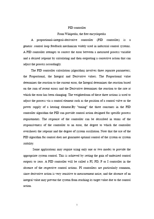
PID controllerFrom Wikipedia, the free encyclopediaA proportional–integral–derivative controller (PID controller) is a generic .control loop feedback mechanism widely used in industrial control systems.A PID controller attempts to correct the error between a measured process variable and a desired setpoint by calculating and then outputting a corrective action that can adjust the process accordingly.The PID controller calculation (algorithm) involves three separate parameters; the Proportional, the Integral and Derivative values. The Proportional value determines the reaction to the current error, the Integral determines the reaction based on the sum of recent errors and the Derivative determines the reaction to the rate at which the error has been changing. The weightedsum of these three actions is used to adjust the process via a control element such as the position of a control valve or the power supply of a heating element.By "tuning" the three constants in the PID controller algorithm the PID can provide control action designed for specific process requirements. The response of the controller can be described in terms of the responsiveness of the controller to an error, the degree to which the controller overshoots the setpoint and the degree of system oscillation. Note that the use of the PID algorithm for control does not guarantee optimal control of the system or system stability.Some applications may require using only one or two modes to provide the appropriate system control. This is achieved by setting the gain of undesired control outputs to zero. A PID controller will be called a PI, PD, P or I controller in the absence of the respective control actions. PI controllers are particularly common, since derivative action is very sensitive to measurement noise, and the absence of an integral value may prevent the system from reaching its target value due to the control action.A block diagram of a PID controllerNote: Due to the diversity of the field of control theory and application, many naming conventions for the relevant variables are in common use.1.Control loop basicsA familiar example of a control loop is the action taken to keep one's shower water at the ideal temperature, which typically involves the mixing of two process streams, cold and hot water. The person feels the water to estimate its temperature. Based on this measurement they perform a control action: use the cold water tap to adjust the process. The person would repeat this input-output control loop, adjusting the hot water flow until the process temperature stabilized at the desired value.Feeling the water temperature is taking a measurement of the process value or process variable (PV). The desired temperature is called the setpoint (SP). The output from the controller and input to the process (the tap position) is called the manipulated variable (MV). The difference between the measurement and the setpoint is the error (e), too hot or too cold and by how much.As a controller, one decides roughly how much to change the tap position (MV) after one determines the temperature (PV), and therefore the error. This first estimate is the equivalent of the proportional action of a PID controller. The integral action of a PID controller can be thought of as gradually adjusting the temperature when it is almost right. Derivative action can be thought of as noticing the water temperature is getting hotter or colder, and how fast, and taking that into account when deciding how to adjust the tap.Making a change that is too large when the error is small is equivalent to a high gain controller and will lead toovershoot. If the controller were to repeatedly make changes that were too large and repeatedly overshoot the target, this control loop would be termed unstable and the output would oscillate around the setpoint in either a constant, growing, or decaying sinusoid. A human would not do this because we are adaptive controllers, learning from the process history, but PID controllers do not have the ability to learn and must be set up correctly. Selecting the correct gains for effective control is known as tuning the controller.If a controller starts from a stable state at zero error (PV = SP), then further changes by the controller will be in response to changes in other measured or unmeasured inputs to the process that impact on the process, and hence on the PV. Variables that impact on the process other than the MV are known as disturbances and generally controllers are used to reject disturbances and/or implement setpoint changes. Changes in feed water temperature constitute a disturbance to the shower process.In theory, a controller can be used to control any process which has a measurable output (PV), a known ideal value for that output (SP) and an input to the process (MV) that will affect the relevant PV. Controllers are used in industry to regulate temperature, pressure, flow rate, chemical composition, speed and practically every other variable for which a measurement exists. Automobile cruise control is an example of a process which utilizes automated control.Due to their long history, simplicity, well grounded theory and simple setup and maintenance requirements, PID controllers are the controllers of choice for many of these applications.2.PID controller theoryNote: This section describes the ideal parallel or non-interacting form of the PID controller. For other forms please see the Section "Alternative notation and PID forms".The PID control scheme is named after its three correcting terms, whose sum constitutes the manipulated variable (MV). Hence:where Pout, Iout, and Dout are the contributions to the output from the PID controller from each of the three terms, as defined below.2.1. Proportional termThe proportional term makes a change to the output that is proportional to the current error value. The proportional response can be adjusted by multiplying the error by a constant Kp, called the proportional gain.The proportional term is given by:WherePout: Proportional outputKp: Proportional Gain, a tuning parametere: Error = SP − PVt: Time or instantaneous time (the present)Change of response for varying KpA high proportional gain results in a large change in the output for a given change in the error. If the proportional gain is too high, the system can become unstable (See the section on Loop Tuning). In contrast, a small gain results in a small output response to a large input error, and a less responsive (or sensitive) controller. If the proportional gain is too low, the control action may be too small when responding to system disturbances.In the absence of disturbances, pure proportional control will not settle at its target value, but will retain a steady state error that is a function of the proportional gain and the process gain. Despite the steady-state offset, both tuning theory and industrial practice indicate that it is the proportional term that should contribute the bulk of the output change.2.2.Integral termThe contribution from the integral term is proportional to both the magnitude of the error and the duration of the error. Summing the instantaneous error over time (integrating the error) gives the accumulated offset that should have been corrected previously. The accumulated error is then multiplied by the integral gain and added to the controller output. The magnitude of the contribution of the integral term to the overall control action is determined by the integral gain, Ki.The integral term is given by:Change of response for varying KiWhereIout: Integral outputKi: Integral Gain, a tuning parametere: Error = SP − PVτ: Time in the past contributing to the integral responseThe integral term (when added to the proportional term) accelerates themovement of the process towards setpoint and eliminates the residual steady-state error that occurs with a proportional only controller. However, since the integral term is responding to accumulated errors from the past, it can cause the present value to overshoot the setpoint value (cross over the setpoint and then create a deviation in the other direction). For further notes regarding integral gain tuning and controller stability, see the section on loop tuning.2.3 Derivative termThe rate of change of the process error is calculated by determining the slope of the error over time (i.e. its first derivative with respect to time) and multiplying this rate of change by the derivative gain Kd. The magnitude of the contribution of the derivative term to the overall control action is termed the derivative gain, Kd.The derivative term is given by:Change of response for varying KdWhereDout: Derivative outputKd: Derivative Gain, a tuning parametere: Error = SP − PVt: Time or instantaneous time (the present)The derivative term slows the rate of change of the controller output and this effect is most noticeable close to the controller setpoint. Hence, derivative control isused to reduce the magnitude of the overshoot produced by the integral component and improve the combined controller-process stability. However, differentiation of a signal amplifies noise and thus this term in the controller is highly sensitive to noise in the error term, and can cause a process to become unstable if the noise and the derivative gain are sufficiently large.2.4 SummaryThe output from the three terms, the proportional, the integral and the derivative terms are summed to calculate the output of the PID controller. Defining u(t) as the controller output, the final form of the PID algorithm is:and the tuning parameters areKp: Proportional Gain - Larger Kp typically means faster response since thelarger the error, the larger the Proportional term compensation. An excessively large proportional gain will lead to process instability and oscillation.Ki: Integral Gain - Larger Ki implies steady state errors are eliminated quicker. The trade-off is larger overshoot: any negative error integrated during transient response must be integrated away by positive error before we reach steady state.Kd: Derivative Gain - Larger Kd decreases overshoot, but slows down transient response and may lead to instability due to signal noise amplification in the differentiation of the error.3. Loop tuningIf the PID controller parameters (the gains of the proportional, integral and derivative terms) are chosen incorrectly, the controlled process input can be unstable, i.e. its output diverges, with or without oscillation, and is limited only by saturation or mechanical breakage. Tuning a control loop is the adjustment of its control parameters (gain/proportional band, integral gain/reset, derivative gain/rate) to the optimum values for the desired control response.The optimum behavior on a process change or setpoint change varies depending on the application. Some processes must not allow an overshoot of the processvariable beyond the setpoint if, for example, this would be unsafe. Other processes must minimize the energy expended in reaching a new setpoint. Generally, stability of response (the reverse of instability) is required and the process must not oscillate for any combination of process conditions and setpoints. Some processes have a degree of non-linearity and so parameters that work well at full-load conditions don't work when the process is starting up from no-load. This section describes some traditional manual methods for loop tuning.There are several methods for tuning a PID loop. The most effective methods generally involve the development of some form of process model, then choosing P, I, and D based on the dynamic model parameters. Manual tuning methods can be relatively inefficient.The choice of method will depend largely on whether or not the loop can be taken "offline" for tuning, and the response time of the system. If the system can be taken offline, the best tuning method often involves subjecting the system to a step change in input, measuring the output as a function of time, and using this response to determine the control parameters.Choosing a Tuning MethodMethodAdvantagesDisadvantagesManual TuningNo math required. Online method.Requires experiencedpersonnel.Ziegler–NicholsProven Method. Online method.Process upset, sometrial-and-error, very aggressive tuning.Software ToolsConsistent tuning. Online or offline method. May includevalve and sensor analysis. Allow simulation before downloading.Some costand training involved.Cohen-CoonGood process models.Some math. Offline method. Only good for first-order processes.3.1 Manual tuningIf the system must remain online, one tuning method is to first set the I and D values to zero. Increase the P until the output of the loop oscillates, then the P shouldbe left set to be approximately half of that value for a "quarter amplitude decay" type response. Then increase D until any offset is correct in sufficient time for the process. However, too much D will cause instability. Finally, increase I, if required, until the loop is acceptably quick to reach its reference after a load disturbance. However, too much I will cause excessive response and overshoot. A fast PID loop tuning usually overshoots slightly to reach the setpoint more quickly; however, some systems cannot accept overshoot, in which case an "over-damped" closed-loop system is required, which will require a P setting significantly less than half that of the P setting causing oscillation.3.2Ziegler –Nichols methodAnother tuning method is formally known as the Ziegler –Nichols method, introduced by John G . Ziegler and Nathaniel B. Nichols. As in the method above, the I and D gains are first set to zero. The "P" gain is increased until it reaches the "critical gain" Kc at which the output of theloop starts to oscillate. Kc and the oscillation period Pc are used to set the gains as shown:3.3 PID tuning softwareMost modern industrial facilities no longer tune loops using the manualcalculation methods shown above. Instead, PID tuning and loop optimization software are used to ensure consistent results. These software packages will gather the data, develop process models, and suggest optimal tuning. Some software packages can even develop tuning by gathering data from reference changes.Mathematical PID loop tuning induces an impulse in the system, and then uses the controlled system's frequency response to design the PID loop values. In loops with response times of several minutes, mathematical loop tuning is recommended, because trial and error can literally take days just to find a stable set of loop values. Optimal values are harder to find. Some digital loop controllers offer a self-tuning feature in which very small setpoint changes are sent to the process, allowing the controller itself to calculate optimal tuning values.Other formulas are available to tune the loop according to different performance criteria.4 Modifications to the PID algorithmThe basic PID algorithm presents some challenges in control applications that have been addressed by minor modifications to the PID form.One common problem resulting from the ideal PID implementations is integralwindup. This can be addressed by:Initializing the controller integral to a desired valueDisabling the integral function until the PV has entered the controllable region Limiting the time period over which the integral error is calculatedPreventing the integral term from accumulating above or below pre-determined boundsMany PID loops control a mechanical device (for example, a valve). Mechanical maintenance can be a major cost and wear leads to control degradation in the form of either stiction or a deadband in the mechanical response to an input signal. The rate of mechanical wear is mainly a function of how often a device is activated to make a change. Where wear is a significant concern, the PID loop may have an output deadband to reduce the frequency of activation of the output (valve). This is accomplished by modifying the controller to hold its output steady if the changewould be small (within the defined deadband range). The calculated output must leave the deadband before the actual output will change.The proportional and derivative terms can produce excessive movement in the output when a system is subjected to an instantaneous "step" increase in the error, such as a large setpoint change. In the case of the derivative term, this is due to taking the derivative of the error, which is very large in the case of an instantaneous step change.5. Limitations of PID controlWhile PID controllers are applicable to many control problems, they can perform poorly in some applications.PID controllers, when used alone, can give poor performance when the PID loop gains must be reduced so that the control system does not overshoot, oscillate or "hunt" about the control setpoint value. The control system performance can be improved by combining the feedback (or closed-loop) control of a PID controller with feed-forward (or open-loop) control. Knowledge about the system (such as the desired acceleration and inertia) can be "fed forward" and combined with the PID output to improve the overall system performance. The feed-forward value alone can often provide the major portion of the controller output. The PID controller can then be used primarily to respond to whatever difference or "error" remains between the setpoint (SP) and the actual value of the process variable (PV). Since the feed-forward output is not affected by the process feedback, it can never cause the control system to oscillate, thus improving the system response and stability.For example, in most motion control systems, in order to accelerate a mechanical load under control, more force or torque is required from the prime mover, motor, or actuator. If a velocity loop PID controller is being used to control the speed of the load and command the force or torque being applied by the prime mover, then it is beneficial to take the instantaneous acceleration desired for the load, scale that value appropriately and add it to the output of the PID velocity loop controller. This means that whenever the load is being accelerated or decelerated, a proportional amount of force is commanded from the prime mover regardless of the feedback value. The PID loop in this situation uses the feedback information to effect any increase or decrease of the combined output in order to reduce the remaining difference between theprocess setpoint and thefeedback value. Working together, the combined open-loop feed-forward controller and closed-loop PID controller can provide a more responsive, stable and reliable control system.Another problem faced with PID controllers is that they are linear. Thus, performance of PID controllers in non-linear systems (such as HV AC systems) is variable. Often PID controllers are enhanced through methods such as PID gain scheduling or fuzzy logic. Further practical application issues can arise from instrumentation connected to the controller. A high enough sampling rate, measurement precision, and measurement accuracy are required to achieve adequate control performance.A problem with the Derivative term is that small amounts of measurement or process noise can cause large amounts of change in the output. It is often helpful to filter the measurements with a low-pass filter in order to remove higher-frequency noise components. However, low-pass filtering and derivative control can cancel each other out, so reducing noise by instrumentation means is a much better choice. Alternatively, the differential band can be turned off in many systems with little loss of control. This is equivalent to using the PID controller as a PI controller.6. Cascade controlOne distinctive advantage of PID controllers is that two PID controllers can be used together to yield better dynamic performance. This is called cascaded PID control. In cascade control there are two PIDs arranged with one PID controlling the set point of another. A PID controller acts as outer loop controller, which controls the primary physical parameter, such as fluid level or velocity. The other controller acts as inner loop controller, which reads the output of outer loop controller as set point, usually controlling a more rapid changing parameter, flowrate or accelleration. It can be mathematically proved that the working frequency of the controller is increased and the time constant of the object is reduced by using cascaded PID controller.[vague]7. Physical implementation of PID controlIn the early history of automatic process control the PID controller was implemented as a mechanical device. These mechanical controllers used a lever, spring and a mass and were often energized by compressed air. These pneumatic controllers were once the industry standard.Electronic analog controllers can be made from a solid-state or tube amplifier, a capacitor and a resistance. Electronic analog PID control loops were often found within more complex electronic systems, for example, the head positioning of a disk drive, the power conditioning of a power supply, or even the movement-detection circuit of a modern seismometer. Nowadays, electronic controllers have largely been replaced by digital controllers implemented with microcontrollers or FPGAs.Most modern PID controllers in industry are implemented in software in programmable logic controllers (PLCs) or as a panel-mounted digital controller. Software implementations have the advantages that they are relatively cheap and are flexible with respect to the implementation of the PID algorithm.8.Alternative nomenclature and PID forms8.1 PseudocodeHere is a simple software loop that implements the PID algorithm:8.2 Ideal versus standard PID formThe form of the PID controller most often encountered in industry, and the one most relevant to tuning algorithms is the "standard form". In this form the Kp gain is applied to the Iout, and Dout terms, yielding:WhereTi is the Integral TimeTd is the Derivative TimeIn the ideal parallel form, shown in the Controller Theory sectionthe gain parameters are related to the parameters of the standard formthroughand Kd = KpTd. This parallel form, where the parameters are treated as simple gains, is the most general and flexible form. However, it is also the form where the parameters have the least physical interpretation and is generally reserved for theoretical treatment of the PID controller. The "standard" form, despite being slightly more complex mathematically, is more common in industry.8.3Laplace form of the PID controllerSometimes it is useful to write the PID regulator in Laplace transform form:Having the PID controller written in Laplace form and having the transfer function of the controlled system, makes it easy to determine the closed-loop transfer function of the system.8.4Series / interacting formAnother representation of the PID controller is the series, or "interacting" form. This form essentially consists of a PD and PI controller in series, and it made early (analog) controllers easier to build. When the controllers later became digital, many kept using the interacting form.[edit] ReferencesLiptak, Bela (1995). Instrument Engineers' Handbook: Process Control. Radnor, Pennsylvania: Chilton Book Company, 20-29. ISBN 0-8019-8242-1.Van, Doren, Vance J. (July 1, 2003). "Loop Tuning Fundamentals". Control Engineering. Red Business Information.Sellers, David. An Overview of Proportional plus Integral plus Derivative Control and Suggestions for Its Successful Application and Implementation (PDF). Retrieved on 2007-05-05.Articles, Whitepapers, and tutorials on PID controlGraham, Ron (10/03/2005). FAQ on PID controller tuning. Retrieved on2007-05-05.PID控制器比例积分微分控制器(PID调节器)是一个控制环,广泛地应用于工业控制系统里的反馈机制。
Labview毕业论文毕业论文中英文资料外文翻译文献
Labview毕业论文毕业论文中英文资料外文翻译文献中英文资料Virtual Instruments Based on Reconfigurable LogicVirtual Instruments advantages of more traditional instruments:中英文资料greatly enhanced the capabilities of traditional instruments.Nevertheless, there are two main factors which limits the application of virtual中英文资料基于虚拟仪器的可重构逻辑虚拟仪器的出现是测量仪器发展历史上的一场革命。
它充分利用最新的计算机技术来实现和扩展仪器的功能,用计算机屏幕可以简单地模拟大多数仪器的调节控制面板,以各种需要的形式表达并且输出检测结果,用计算机软件实现大部分信号的分析和处理,完成大多数控制和检测功能。
用户通过应用程序将一般的通用计算机与功能化模块硬件结合起来,通过友好的界面来操作计算机,就像在操作自己定义,自己设计的单个仪器,可完成对被测量的采集,分析,判断,控制,显示,数据存储等。
虚拟仪器较传统仪器的优点(1)融合计算机强大的硬件资源,突破了传统仪器在数据处理,显示,存储等方面的限制,大大增强了传统仪器的功能。
(2)利用计算机丰富的软件资源,实现了部分仪器硬件的软件化,节省了物质资源,增加了系统灵活性。
通过软件技术和相应数值算法,实时,直接地对测试数据进行各种分析与处理,通过图形用户界面技术,真正做到界面友好、人中英文资料机交互。
(3)虚拟仪器的硬件和软件都具有开放性,模块化,可重复使用及互换性等特点。
因此,用户可根据自己的需要,选用不同厂家的产品,使仪器系统的开发更为灵活,效率更高,缩短系统组建时间。
传统的仪器是以固定的硬件和软件资源为基础的specific系统,这使得系统的功能和应用程序由制造商定义。
一篇外文文献和翻译(智能家居方面)++
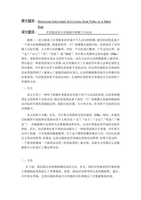
原文题目:Detecting Individual Activities from Video in a SmartHome译文题目:在智能家居中从视频中检测个人活动摘要——论文阐述了在智能家居环境中个人活动的检测。
我们的系统是基于一个强大的视频跟踪器,创建和使用一个广角摄像头跟踪目标。
该系统采了对用输入目标位置,大小和方向的翻译。
对每一个目标进行翻译,产生活动分类,如“走”,“站立”,“坐”,“吃饭”,或“睡眠”。
贝叶斯分类器和支持向量机(SVMs)相比,获取和识别到先前定义的单个活动。
这些方法在记录的数据集上被评估。
然后提出一种新型的混合分类器。
此分类器结合了生成的贝叶斯方法和区别性支持向量机。
贝叶斯方法用于检测先前地看不见的活动,而支持向量机在识别获取活动类别的例子上被展示了能提供搞的区别力。
记录的数据集的混合分类器评估结果表明,当识别系统看不见的活动时,生成和区别性的分类相结合方法的优于单独的方法。
一,引言本文介绍了一种用于检测在智能家居环境下的个人活动的系统。
目的是检测预定义的和看不见的活动。
提出的系统是基于使用一个广角摄像头创建和跟踪移动目标的可视化的跟踪过程。
提取目标位置,大小和方向,作为每个目标的活动识别输入。
本文的两个贡献:首先,贝叶斯分类器和支持向量机(SVMs)相比,从视觉目标属性中获取和识别基本的个人的活动(“走”,“站立”,“会议”,“吃饭”,“睡觉”)。
在数据集中这两种方法都被测试和评估,记录在智能家居环境的实验室样机。
其次,为识别预先看不到的活动提出了一种新型的混合分类器。
贝叶斯方法用于创建一个有依据的数据模型。
关于这个模型的概率确定与否,可以归结预定义的活动种类。
如果是,支持向量机是用来确定获取活动种类。
如果不是这样,一个错误检测或一个新的活动类(所获取到的)被识别。
该混合分类器在记录数据集中已经进行了测定和评估。
二,方法在下面,我们提出从视频检测活动的方法。
首先,我们对智能家居环境和强大视频跟踪系统进行了简要描述。
中英文中英文文献翻译-RFID的历史
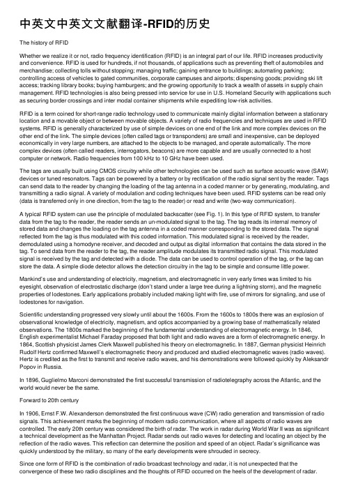
中英⽂中英⽂⽂献翻译-RFID的历史The history of RFIDWhether we realize it or not, radio frequency identification (RFID) is an integral part of our life. RFID increases productivity and convenience. RFID is used for hundreds, if not thousands, of applications such as preventing theft of automobiles and merchandise; collecting tolls without stopping; managing traffic; gaining entrance to buildings; automating parking; controlling access of vehicles to gated communities, corporate campuses and airports; dispensing goods; providing ski lift access; tracking library books; buying hamburgers; and the growing opportunity to track a wealth of assets in supply chain management. RFID technologies is also being pressed into service for use in U.S. Homeland Security with applications such as securing border crossings and inter modal container shipments while expediting low-risk activities.RFID is a term coined for short-range radio technology used to communicate mainly digital information between a stationary location and a movable object or between movable objects. A variety of radio frequencies and techniques are used in RFID systems. RFID is generally characterized by use of simple devices on one end of the link and more complex devices on the other end of the link. The simple devices (often called tags or transponders) are small and inexpensive, can be deployed economically in very large numbers, are attached to the objects to be managed, and operate automatically. The more complex devices (often called readers, interrogators, beacons) are more capable and are usually connected to a host computer or network. Radio frequencies from 100 kHz to 10 GHz have been used.The tags are usually built using CMOS circuitry while other technologies can be used such as surface acoustic wave (SAW) devices or tuned resonators. Tags can be powered by a battery or by rectification of the radio signal sent by the reader. Tags can send data to the reader by changing the loading of the tag antenna in a coded manner or by generating, modulating, and transmitting a radio signal. A variety of modulation and coding techniques have been used. RFID systems can be read only (data is transferred only in one direction, from the tag to the reader) or read and write (two-way communication).A typical RFID system can use the principle of modulated backscatter (see Fig. 1). In this type of RFID system, to transfer data from the tag to the reader, the reader sends an un-modulated signal to the tag. The tag reads its internal memory of stored data and changes the loading on the tag antenna in a coded manner corresponding to the stored data. The signal reflected from the tag is thus modulated with this coded information. This modulated signal is received by the reader, demodulated using a homodyne receiver, and decoded and output as digital information that contains the data stored in the tag. To send data from the reader to the tag, the reader amplitude modulates its transmitted radio signal. This modulated signal is received by the tag and detected with a diode. The data can be used to control operation of the tag, or the tag can store the data. A simple diode detector allows the detection circuitry in the tag to be simple and consume little power. Mankind’s use and understanding of electricity, magnetism, and electromagnetic in very early times was limited to his eyesight, observation of electrostatic discharge (don’t stand under a large tree during a lightning storm), and the magnetic properties of lodestones. Early applications probably included making light with fire, use of mirrors for signaling, and use of lodestones for navigation.Scientific understanding progressed very slowly until about the 1600s. From the 1600s to 1800s there was an explosion of observational knowledge of electricity, magnetism, and optics accompanied by a growing base of mathematically related observations. The 1800s marked the beginning of the fundamental understanding of electromagnetic energy. In 1846, English experimentalist Michael Faraday proposed that both light and radio waves are a form of electromagnetic energy. In 1864, Scottish physicist James Clerk Maxwell published his theory on electromagnetic. In 1887, German physicist Heinrich Rudolf Hertz confirmed Maxwell’s electromagnetic theory and produced and studied electromagnetic waves (radio waves). Hertz is credited as the first to transmit and receive radio waves, and his demonstrations were followed quickly by Aleksandr Popov in Russia.In 1896, Guglielmo Marconi demonstrated the first successful transmission of radiotelegraphy across the Atlantic, and the world would never be the same.Forward to 20th centuryIn 1906, Ernst F.W. Alexanderson demonstrated the first continuous wave (CW) radio generation and transmission of radio signals. This achievement marks the beginning of modern radio communication, where all aspects of radio waves are controlled. The early 20th century was considered the birth of radar. The work in radar during World War II was as significant a technical development as the Manhattan Project. Radar sends out radio waves for detecting and locating an object by the reflection of the radio waves. This reflection can determine the position and speed of an object. Radar’s significance was quickly understood by the military, so many of the early developments were shrouded in secrecy.Since one form of RFID is the combination of radio broadcast technology and radar, it is not unexpected that the convergence of these two radio disciplines and the thoughts of RFID occurred on the heels of the development of radar.Genesis of an ideaAn early, if not the first, work exploring RFID is the landmark paper by Harry Stockman, “Communication by Means of Reflected Power,” published in 1948. Stockman stated “Evidently, considerable research and development work has to be done before the remaining basic problems in reflected-power communication are solved, and before the field of useful applications is explored.”Thirty years would pass before Stockman’s vision would reach fruition. Other developments were needed: the transistor, the integrated circuit, the microprocessor, development ofcommunication networks, and changes in ways of doing business. The success of RFID would have to wait a while.Much has happened in the 57 years since Stockman’s work. The 1950s were an era of exploration of RFID techniques following technical developments in radio and radar in the 1930s and 1940s. Several technologies related to RFID were being explored such as the long range transponder systems of “identification, friend, or foe” (IFF) for aircraft.Developments of the 1950s include such works as D.B. Harris’s “Radio transmission systems with modulatable passive responder.” The wheels of RFID development were turning.RFID becomes realityThe 1960s were the prelude to the RFID explosion of the 1970s. R.F. Harrington studied the electromagnetic theory related to RFID in his papers including “Theory of Loaded Scatterers” in 1964. Inventors were busy with RFID-related inventions such as Robert Richardson’s “Remotely activated radio frequency powered devices,” and J. H. Vogelman’s “Passive data transmission techniques utilizing radar echoes.”Commercial activities were beginning in the 1960s. Sensormatic and Checkpoint were founded in the late 1960s. These companies, with others such as Knogo, developed electronic article surveillance (EAS) equipment to counter the theft of merchandise. These types of systems are often use 1-b tags; only the presence or absence of a tag could be detected, but the tags could be made inexpensively and provided effective antitheft measures. These types of systems used either microwave (generation of harmonics using a semiconductor) or inductive (resonant circuits) technology. EAS is arguably the first and most widespread commercial use of RFID. Tags containing multiple bits were generally experimental in nature and were built with discrete components. While single-bit EAS tags were small, multi-bit tags were the size of a loaf of bread, constrained in size by the dictates of the circuitry.In the 1970s developers, inventors, companies, academic institutions, and government laboratories were actively working on RFID, and notable advances were being realized at research laboratories and academic institutions such as Los Alamos Scientific Laboratory, Northwestern University, and the Microwave Institute Foundation in Sweden. An early and important development was the Los Alamos work that was presented by Alfred Koelle, Steven Depp, and Robert Freyman, “Short-Range Radio-Telemetry for Electronic Identification Using Modulated Backscatter,” in 1975. This development signaled the beginning of practical, completely passive tags with an operational range of tens of meters. Large companies were also developing RFID technology, such as Raytheon’s Raytag in 1973 and Richard Klensch of RCA developing an electronic identification system in 1975.The Port Authority of New York and New Jersey was also testing systems built by General Electric, Westinghouse, Philips, and Glenayre. Results were favorable, but the first commercially successful transportation application of RFID, electronic toll collection, was not yet ready forThe 1970s were characterized primarily by developmental work. Intended applications were for animal tracking, vehicle tracking, and factory automation. Examples of animal tagging efforts were the microwave systems at Los Alamos and Identronix and the inductive systems in Europe. Interest in animal tagging was high in Europe. Alfa Laval, Nedap, and others were developing RFID systems.Transportation efforts included work at Los Alamos and by the International Bridge Turnpike and Tunnel Association (IBTTA) and the United States Federal Highway Administration. The latter two sponsored a conference in 1973 that concluded there was no national interest in developing a standard for electronic vehicle identification. This is an important decision since it would permit a variety of systems to develop, which was good, because RFID technology was in its infancy. Research efforts continued as well. R.J. King authored a book about microwave homodyne techniques in 1978. This book is an early compendium of theory and practice used in backscatter RFID systems.Tag technology had improved with reductions in size and improvements in functionality. The key to these advancements was the use of low-voltage, low power CMOS logic circuits. Tag memory utilized switches or wire bonds and had improved with use of fusible link diode arrays by the end of the decade.The 1980s became the decade for full implementation of RFID technology, though interests developed somewhat differently in various parts of the world. The greatest interests in the United States were for transportation, personnel access, and, to alesser extent, animals. In Europe, the greatest interests were for short-range systems for animals and industrial and business applications, though toll roads in Italy, France, Spain, Portugal, and Norway were equipped with RFID. A key to the rapid expansion of RFID applications was the development of the personal computer (PC) that allowed convenient and economical collection and management of data from RFID systems.In the Americas, the Association of American Railroads and the Container Handling Cooperative Program were active with RFID initiatives. Tests of RFID for collecting tolls had been going on for many years, and the first commercial application began in Europe in 1987 in Norway and was followed quickly in the United States by the Dallas North Turnpike in 1989. Also during this time, the Port Authority of New York and New Jersey began commercial operation of RFID for buses going through the Lincoln Tunnel. RFID was finding a home with electronic toll collection, and new players were arriving daily. Tags were now being built using custom CMOS integrated circuits combined with discrete components for microwave tags. EEPROM became the nonvolatile memory of choice, permitting the large-scale manufacture of identical tags that could be individualized through programming. These advancements lead to further reductions in the size of tags and increase in functionality (see Fig. 2). The constraint of required antenna size was now becoming important in determining theThe 1990sThe 1990s were a significant decade for RFID since it saw the wide scale deployment of electronic toll collection in the United States and the installation of over 3 million RFID tags on rail cars in North America. Important deployments included several innovations in electronic tolling. The world’s first open highway electronic tolling system opened in Oklahoma in 1991, where vehicles could pass toll collection points at highway speeds, unimpeded by a toll plaza or barriers and with video cameras for enforcement. The first combined toll collection and traffic management system was installed in the Houston area by the Harris County Toll Road Authority in 1992. Also a first was the system installed on the Kansas turnpike using readers that could also operate with the different protocol tags of their neighbor to the south, Oklahoma. Georgia would follow, upgrading their equipment with readers that could communicate with tags using a new protocol as well as their existing tags. In fact, these two installations were the first to implement a multi-protocol capability in electronic toll collection applications.In the northeastern United States, seven regional toll agencies formed the E-Z Pass Interagency Group (IAG) in 1990 to develop a regionally compatible electronic toll collection system. This system is the model for using a single tag and single billing account per vehicle to access highways and bridges of several toll authorities.Interest was also keen for RFID applications in Europe during the 1990s. Both microwave and inductive technologies were finding use for toll collection, access control, and a wide variety of other applications in commerce.A new effort underway was the development of the Texas Instruments (TI) TIRIS system, used in many automobiles for control of the starting of the vehicle engine. The TIRIS system (and others such as from Mikron, now a part of Philips) developed new applications for dispensing fuel, gaming chips, ski passes, and vehicle access.Additional companies in Europe were becoming active in the RFID race as well with developments including Microdesign, CGA, Alcatel, Bosch and the Philips spinoffs of Combitech, Baumer, and Tagmaster. A pan-European standard was needed for tolling applications in Europe, and many of these companies (and others) were at work on the CEN standard for electronic tolling.Tolling and rail applications were also appearing in many countries including Australia, China, Hong Kong, Philippines, Argentina, Brazil, Mexico, Canada, Japan, Malaysia, Singapore, Thailand, South Korea, South Africa, and Europe.With the success of electronic toll collection, other advancements followed such as the first multiple use of tags across different business segments. Now, a single tag (with dual or single billing accounts) could be used for electronic toll collection, parking lot access and fare collection, gated community access, and campus access. In the Dallas–Ft. Worth metroplex, a first wasachieved when a single TollTag on a vehicle could be used to pay tolls on the North Dallas Tollway, for access and parking payment at the Dallas/Ft. Worth International Airport, the nearby Love Field, and several downtown parking garages as well as access to gated communities and business campuses.Research and development didn’t slow down during the 1990s with new technological developments expanding the functionality of RFID. For the first time, useful microwave Schottky diodes were fabricated on a regular CMOS integrated circuit. This development permitted the construction of microwave RFID tags that contained only a single integrated circuit, a capability previously limited to inductively coupled RFID transponders. Books began to appear devoted specifically to RFID technology. Klaus Finkenzeller wrote one of the first in 1999.With the growing interest of RFID into the item management arena and the opportunity for RFID to work along side bar code, it becomes difficult in the later part of this decade to count the number of companies who enter the marketplace. Many havecome and gone, many are still here, many have merged, and there are many new players ... it seems almost daily!Back to the future: The 21st centuryThe 21st century opens with the smallest microwave tags built using, at a minimum, two components: a single custom CMOS integrated circuit and an antenna. Tags could now be built as sticky labels, easily attached to windshields and objects to be managed. The use of RFID for electronic toll collection had expanded in the United States to 3,500 lanes of traffic by 2001. EEPROM remained the nonvolatile memory of choice. The search continues for a fast nonvolatile memory suited to the requirements of RFID. The size of tags is now limited by the constraints of the antenna. The design of suitable antennas and the search for better nonvolatile memory are continuing design challenges.The impact of RFID is lauded regularly in mainstream media, with the use of RFID slated to become even more ubiquitous. The growing interest in telemetric, article tracking and mobile commerce will bring RFID even closer to the consumer. The U.S. Federal Communications Commission (FCC) allocated spectrum in the 5.9 GHz band for a vast expansion of intelligent transportation systems with many new applications and services proposed. But the equipment required to accommodate these new applications and services will necessitate advancements beyond the “traditional” RFID technology.This next generation of short-range communication systems between roadside and vehicle are presently being standardized within the IEEE and are based on wireless LAN techniques.Supply chain management and article tracking are RFID application areas that have grown rapidly spurred by the technical breakthrough of the late 1990s to incorporate microwave diodes in silicon on the same die as the tag circuitry. This development allows a reduction in the size of circuitry, reduction in cost of tags, increased functionality, and increased reliability. The Auto-ID center was organized at the Massachusetts Institute of Technology to bring together RFID manufacturers, researchers, and users to develop standards, perform research, and share information for supply chain applications. EPC Global has assumed the task of standards for this application area. The International Standards Organization also has very active standards activities for a variety of application areas.The pace of developments in RFID continues to accelerate. The future looks very promising for this technology. The full potential also requires advancements in other areas as well such as development of applications software; careful development of privacy policies and consideration of other legal aspects; development of supporting infrastructure to design, install, and maintain RFID systems; and other such activities now that RFID has truly entered the mainstream.At first glance, the concept of RFID and its application seems simple and straightforward. But in reality, the contrary is true. RFID is a technology that spans systems engineering, software development, circuit theory, antenna theory, radio propagation, microwave techniques, receiver design, integrated circuit design, encryption, materials technology, mechanical design, and network engineering, to mention a few. Increasing numbers of engineers are involved in the development and application of RFID, and this trend will likely continue. At present, the shortage of technical and business people trained in RFID is hampering the growth of the industry.As we create our future, and it is bright, let us remember, “Nothing great was ever achieved without enthusiasm”(Ralph Waldo Emerson). We have a great many developments to look forward to, history continues to teach us that.RFID的历史⽆论我们是否意识到,⽆线射频识别技术(RFID)成为了我们⽣活中的⼀部分。
单片机的外文文献及中文翻译

单片机的外文文献及中文翻译一、外文文献Title: The Application and Development of SingleChip Microcontrollers in Modern ElectronicsSinglechip microcontrollers have become an indispensable part of modern electronic systems They are small, yet powerful integrated circuits that combine a microprocessor core, memory, and input/output peripherals on a single chip These devices offer significant advantages in terms of cost, size, and power consumption, making them ideal for a wide range of applicationsThe history of singlechip microcontrollers can be traced back to the 1970s when the first microcontrollers were developed Since then, they have undergone significant advancements in technology and performance Today, singlechip microcontrollers are available in a wide variety of architectures and capabilities, ranging from simple 8-bit devices to complex 32-bit and 64-bit systemsOne of the key features of singlechip microcontrollers is their programmability They can be programmed using various languages such as C, Assembly, and Python This flexibility allows developers to customize the functionality of the microcontroller to meet the specific requirements of their applications For example, in embedded systems for automotive, industrial control, and consumer electronics, singlechip microcontrollers can be programmed to control sensors, actuators, and communication interfacesAnother important aspect of singlechip microcontrollers is their low power consumption This is crucial in batterypowered devices and portable electronics where energy efficiency is of paramount importance Modern singlechip microcontrollers incorporate advanced power management techniques to minimize power consumption while maintaining optimal performanceIn addition to their use in traditional electronics, singlechip microcontrollers are also playing a significant role in the emerging fields of the Internet of Things (IoT) and wearable technology In IoT applications, they can be used to collect and process data from various sensors and communicate it wirelessly to a central server Wearable devices such as smartwatches and fitness trackers rely on singlechip microcontrollers to monitor vital signs and perform other functionsHowever, the design and development of systems using singlechip microcontrollers also present certain challenges Issues such as realtime performance, memory management, and software reliability need to be carefully addressed to ensure the successful implementation of the applications Moreover, the rapid evolution of technology requires developers to constantly update their knowledge and skills to keep up with the latest advancements in singlechip microcontroller technologyIn conclusion, singlechip microcontrollers have revolutionized the field of electronics and continue to play a vital role in driving technological innovation Their versatility, low cost, and small form factor make them an attractive choice for a wide range of applications, and their importance is expected to grow further in the years to come二、中文翻译标题:单片机在现代电子领域的应用与发展单片机已成为现代电子系统中不可或缺的一部分。
智能医疗系统毕业论文中英文资料外文翻译文献

智能医疗系统毕业论文中英文资料外文翻译文献AbstractThe field of healthcare has greatly benefited from the advances in technology, particularly with the development of intelligent healthcare systems. These systems utilize artificial intelligence (AI) to improve the quality and efficiency of healthcare services. This literature review aims to provide an overview of the current state of intelligent healthcare systems and their applications in the medical field.IntroductionKey Features of Intelligent Healthcare Systems1. Real-Time Monitoring: Intelligent healthcare systems facilitate real-time monitoring of patients' vital signs, allowing healthcare professionals to detect any abnormalities and intervene in a timely manner.Real-Time Monitoring: Intelligent healthcare systems facilitatereal-time monitoring of patients' vital signs, allowing healthcare professionals to detect any abnormalities and intervene in a timely manner.2. Predictive Analytics: By analyzing vast amounts of patient data, these systems can identify patterns and trends to predict potential health risks or deteriorations, enabling proactive interventions.Predictive Analytics: By analyzing vast amounts of patient data, these systems can identify patterns and trends to predict potential health risks or deteriorations, enabling proactive interventions.3. Personalized Medicine: Intelligent healthcare systems can utilize patient-specific data to provide personalized treatment plans, taking into account individual characteristics and medical history.Personalized Medicine: Intelligent healthcare systems can utilize patient-specific data to provide personalized treatment plans, taking into account individual characteristics and medical history.4. Remote Patient Management: Through the use of telemedicine technologies, intelligent healthcare systems enable remote patientmonitoring and virtual consultations, enhancing access to healthcare services and reducing the need for in-person visits.Remote Patient Management: Through the use of telemedicine technologies, intelligent healthcare systems enable remote patient monitoring and virtual consultations, enhancing access to healthcare services and reducing the need for in-person visits.Applications of Intelligent Healthcare Systems1. Chronic Disease Management: Intelligent healthcare systems can aid in the management of chronic conditions such as diabetes, cardiovascular diseases, and respiratory disorders. They provide patients with tools for self-management and assist healthcare professionals in monitoring the disease progression.Chronic Disease Management: Intelligent healthcare systems can aid in the management of chronic conditions such as diabetes, cardiovascular diseases, and respiratory disorders. They provide patients with tools for self-management and assist healthcare professionals in monitoring the disease progression.2. Hospital Workflow Optimization: These systems can optimize hospital workflows by automating administrative tasks, streamlining patient admission and discharge processes, and improving resource allocation.Hospital Workflow Optimization: These systems can optimize hospital workflows by automating administrative tasks, streamlining patient admission and discharge processes, and improving resource allocation.3. Drug Safety and Adherence: Intelligent healthcare systems can help prevent medication errors and improve patient adherence to prescribed treatments through reminders, alerts, and medication tracking.Drug Safety and Adherence: Intelligent healthcare systems can help prevent medication errors and improve patient adherence to prescribed treatments through reminders, alerts, and medication tracking.4. Healthcare Data Analysis: By collecting and analyzing large volumes of healthcare data, these systems can provide valuable insights for medical research, disease surveillance, and public health planning.Healthcare Data Analysis: By collecting and analyzing largevolumes of healthcare data, these systems can provide valuable insights for medical research, disease surveillance, and public health planning.ConclusionReferences[1] Smith, J. (2019). The role of intelligent healthcare systems in transforming healthcare delivery. Journal of Healthcare Technology,8(2), 45-56.[2] Johnson, A., et al. (2018). Applications of artificial intelligence in healthcare: Current trends and future prospects. International Journal of Medical Informatics, 115, 1-7.[3] Rodrigues, J., et al. (2020). Intelligent healthcare systems: State-of-the-art and future challenges. Journal of Medical Systems, 44(3), 1-15.。
- 1、下载文档前请自行甄别文档内容的完整性,平台不提供额外的编辑、内容补充、找答案等附加服务。
- 2、"仅部分预览"的文档,不可在线预览部分如存在完整性等问题,可反馈申请退款(可完整预览的文档不适用该条件!)。
- 3、如文档侵犯您的权益,请联系客服反馈,我们会尽快为您处理(人工客服工作时间:9:00-18:30)。
中英文资料外文翻译文献Introduction of smart cardA smart card, chip card, or integrated circuit card (ICC), is in any pocket-sized card with embedded integrated circuits which can process data. This implies that it can receive input which is processed —by way of the ICC applications —and delivered as an output. There are two broad categories of ICCs. Memory cards contain only non-volatile memory storage components, and perhaps some specific security logic. Microprocessor cards contain volatile memory and microprocessor components. The card is made of plastic, generally PVC, but sometimes ABS. The card may embed a hologram to avoid counterfeiting. Using smartcards also is a form of strong security authentication for single sign-on within large companies and organizations.●OverviewA "smart card" is also characterized as follows:◆Dimensions are normally credit card size. The ID-1 of ISO/IEC 7810standard defines them as 85.60 × 53.98 mm. Another popular size is ID-000which is 25 ×15 mm (commonly used in SIM cards). Both are 0.76 mmthick.◆Contains a security system with tamper-resistant properties (e.g. a securecryptoprocessor, secure file system, human-readable features) and is capableof providing security services (e.g. confidentiality of information in thememory).◆Asset managed by way of a central administration system which interchangesinformation and configuration settings with the card through the securitysystem. The latter includes card hotlisting, updates for application data.◆Card data is transferred to the central administration system through cardreading devices, such as ticket readers, ATMs etc.●BenefitsSmart cards can be used for identification, authentication, and data storage.[1] Smart cards provide a means of effecting business transactions in a flexible, secure, standard way with minimal human intervention.Smart card can provide strong authentication[2] for single sign-on or enterprise single sign-on to computers, laptops, data with encryption, enterprise resource planning platforms such as SAP, etc.●HistoryThe automated chip card was invented by German rocket scientist Helmut Gröttrup and his colleague Jürgen Dethloff in 1968; the patent was finally approved in 1982. The first mass use of the cards was for payment in French pay phones, starting in 1983 (Telecarte).Roland Moreno actually patented his first concept of the memory card in 1974. In 1977, Michel Ugon from Honeywell Bull invented the first microprocessor smart card. In 1978, Bull patented the SPOM (Self Programmable One-chip Microcomputer) that defines the necessary architecture to auto-program the chip. Three years later, the very first "CP8" based on this patent was produced by Motorola. At that time, Bull had 1200 patents related to smart cards. In 2001, Bull sold its CP8 Division together with all its patents to Schlumberger. Subsequently, Schlumberger combined its smart card department and CP8 and created Axalto. In 2006, Axalto and Gemplus, at the time the world's no.2 and no.1 smart card manufacturers, merged and became Gemalto.A smart card, combining credit card and debit card properties. The 3 by 5 mm security chip embedded in the card is shown enlarged in the inset. The contact pads on the card enables electronic access to the chip.The second use was with the integration of microchips into all French debit cards (Carte Bleue) completed in 1992. When paying in France with a Carte Bleue, one inserts the card into the merchant's terminal, then types the PIN, before the transaction is accepted. Only very limited transactions (such as paying small autoroute tolls) are accepted without PIN.Smart-card-based electronic purse systems (in which value is stored on the card chip, not in an externally recorded account, so that machines accepting the card need no network connectivity) were tried throughout Europe from the mid-1990s, most notably in Germany (Geldkarte), Austria (Quick), Belgium (Proton), France (Moneo), the Netherlands (Chipknip and Chipper), Switzerland ("Cash"), Norway ("Mondex"), Sweden ("Cash"), Finland ("Avant"), UK ("Mondex"), Denmark ("Danmønt") and Portugal ("Porta-moedas Multibanco").The major boom in smart card use came in the 1990s, with the introduction of the smart-card-based SIM used in GSM mobile phone equipment in Europe. With the ubiquity of mobile phones in Europe, smart cards have become very common.The international payment brands MasterCard, Visa, and Europay agreed in 1993 to work together to develop the specifications for the use of smart cards in payment cards used as either a debit or a credit card. The first version of the EMV system was released in 1994. In 1998 a stable release of the specifications was available. EMVco, the company responsible for the long-term maintenance of the system, upgraded the specification in 2000 and most recently in 2004. The goal of EMVco is to assure the various financial institutions and retailers that the specifications retain backward compatibility with the 1998 version.With the exception of countries such as the United States of America there has been significant progress in the deployment of EMV-compliant point of sale equipment and the issuance of debit and or credit cards adhering the EMV specifications. Typically, a country's national payment association, in coordination with MasterCard International, Visa International, American Express and JCB,develop detailed implementation plans assuring a coordinated effort by the various stakeholders involved.The backers of EMV claim it is a paradigm shift in the way one looks at payment systems. In countries where banks do not currently offer a single card capable of supporting multiple account types, there may be merit to this statement. Though some banks in these countries are considering issuing one card that will serve as both a debit card and as a credit card, the business justification for this is still quite elusive. Within EMV a concept called Application Selection defines how the consumer selects which means of payment to employ for that purchase at the point of sale.For the banks interested in introducing smart cards the only quantifiable benefit is the ability to forecast a significant reduction in fraud, in particular counterfeit, lost and stolen. The current level of fraud a country is experiencing, coupled with whether that country's laws assign the risk of fraud to the consumer or the bank, determines if there is a business case for the financial institutions. Some critics claim that the savings are far less than the cost of implementing EMV, and thus many believe that the USA payments industry will opt to wait out the current EMV life cycle in order to implement new, contactless technology.Smart cards with contactless interfaces are becoming increasingly popular for payment and ticketing applications such as mass transit. Visa and MasterCard have agreed to an easy-to-implement version currently being deployed (2004-2006) in the USA. Across the globe, contactless fare collection systems are being implemented to drive efficiencies in public transit. The various standards emerging are local in focus and are not compatible, though the MIFARE Standard card from Philips has a considerable market share in the US and Europe.Smart cards are also being introduced in personal identification and entitlement schemes at regional, national, and intern ational levels. Citizen cards, drivers’ licenses, and patient card schemes are becoming more prevalent; For example in Malaysia, the compulsory national ID scheme MyKad includes 8 different applications and is rolled out for 18 million users. Contactless smart cards are being integrated into ICAO biometric passports to enhance security for international travel.●Contact smart cardContact smart cards have a contact area, comprising several gold-plated contact pads, that is about 1 cm square. When inserted into a reader, the chip makes contact with electrical connectors that can read information from the chip and write information back.[3]The ISO/IEC 7816 and ISO/IEC 7810 series of standards define:◆the physical shape◆the positions and shapes of the electrical connectors◆the electrical characteristics◆the communications protocols, that includes the format of the commands sentto the card and the responses returned by the card.◆robustness of the cardthe functionalityThe cards do not contain batteries; energy is supplied by the card reader.Electrical signals description◆A smart card pinoutVCC : Power supply input◆RST : Either used itself (reset signal supplied from the interface device) or incombination with an internal reset control circuit (optional use by the card).If internal reset is implemented, the voltage supply on Vcc is mandatory.◆CLK : Clocking or timing signal (optional use by the card).◆GND : Ground (reference voltage).◆VPP : Programming voltage input (deprecated / optional use by the card).◆I/O : Input or Output for serial data to the integrated circuit inside the card.◆NOTE - The use of the two remaining contacts will be defined in theappropriate application standards.●ReaderContact smart card readers are used as a communications medium between the smart card and a host, e.g. a computer, a point of sale terminal, or a mobile telephone.Since the chips in the financial cards are the same as those used for mobile phone Subscriber Identity Module (SIM) cards, just programmed differently and embedded in a different shaped piece of PVC, the chip manufacturers are building to the more demanding GSM/3G standards. So, for instance, although EMV allows a chip card to draw 50 mA from its terminal, cards are normally well inside the telephone industry's 6mA limit. This is allowing financial card terminals to become smaller and cheaper, and moves are afoot to equip every home PC with a card reader and software to make internet shopping more secure.[citation needed]●Contactless smart cardA second type is the contactless smart card, in which the chip communicates with the card reader through RFID induction technology (at data rates of 106 to 848 kbit/s). These cards require only close proximity to an antenna to complete transaction. They are often used when transactions must be processed quickly or hands-free, such as on mass transit systems, where smart cards can be used without even removing them from a wallet.The standard for contactless smart card communications is ISO/IEC 14443. It defines two types of contactless cards ("A" and "B"), allows for communications at distances up to 10 cm. There had been proposals for ISO/IEC 14443 types C, D, E and F that have been rejected by the International Organization for Standardization. An alternative standard for contactless smart cards is ISO 15693, which allows communications at distances up to 50 cm.Examples of widely used contactless smart cards are Hong Kong's Octopus card, South Korea's T-money (Bus, Subway, Taxi), London's Oyster card, Japan Rail's Suica Card and Mumbai Bus transportation service BEST uses smart cards for bus pass, which predate the ISO/IEC 14443 standard. All of them are primarily designed for public transportation payment and other electronic purse applications.A related contactless technology is RFID (radio frequency identification). In certain cases, it can be used for applications similar to those of contactless smart cards, such as for electronic toll collection. RFID devices usually do not include writeable memory or microcontroller processing capability as contactless smart cards often do.Like smart cards with contacts, contactless cards do not have a battery. Instead, they use a built-in inductor to capture some of the incident radio-frequency interrogation signal, rectify it, and use it to power the card's electronics.●Cryptographic smart cardsCryptographic smart cards are often used for single sign-on. Most advanced smart cards are equipped with specialized cryptographic hardware that let you use algorithms such as RSA and DSA on board. Today's cryptographic smart cards are also able to generate key pairs on board, to avoid the risk of having more than one copy of the key (since by design there usually isn't a way to extract private keys from a smart card).Such smart cards are mainly used for digital signature and secure identification, (see applications section). [4]The most common way to access cryptographic smart card functions on a computer is to use a PKCS#11 library provided by the vendor. On Microsoft Windows platforms the CSP API is also adopted.The most widely used cryptographic algorithms in smart cards (excluding the GSM so-called "crypto algorithm") are 3DES (Triple DES) and RSA. The key set is usually loaded (DES) or generated (RSA) on the card at the personalization stage.●Computer securityThe Mozilla Firefox web browser can use smart cards to store certificates for use in secure web browsing[5].Some disk encryption systems, such as FreeOTFE or TrueCrypt, can use smart cards to securely hold encryption keys, and also to add another layer of encryption to critical parts of the secured disk[6].Smartcards are also used for single sign-on to log on to computersSmartcards support functionality has been added to Windows Live Passports●FinancialThe applications of smart cards include their use as credit or ATM cards, in a fuel card, SIMs for mobile phones, authorization cards for pay television, pre-pay utilities in household, high-security identification and access-control cards, and public transport and public phone payment cards.Smart cards may also be used as electronic wallets. The smart card chip can be loaded with funds which can be spent in parking meters and vending machines or at various merchants. Cryptographic protocols protect the exchange of money between the smart card and the accepting machine. There is no connection to the issuing bank necessary, so the holder of the card can use it regardless of him being the owner. The German Geldkarte is also used to validate the customers age at vending machines for cigarettes.智能卡简介智能卡、芯片卡或IC卡(ICC ),是指任何具有嵌入式集成电路并且可处理信息的袖珍卡。