施耐德按钮教材
施耐德CAP1自动转换开关电器安装使用说明书

CAP1自动转换开关电器安装使用说明书开关本体:打开包装,应有下列零部件Open the package, there are following partsCAP1 AUTOMATIC TRANSFER SWITCHING EQUIPMENT MOUNTING OPERATION MANUALBasic switchNote: the relevent outline diagrams of detailedspecifications are seen this pages of outline andmounting dimensions of the operation manual.1)J type controller of 2-pole product is internal type, without this accessory.2)There is accessory when E or Z type controller is selected.3)The busbars are optionally equipped, when selecting, there are accessories.4)There are fasteners specifications in bracket.5)xA/B: number is A for 3-pole product, B for 4-pole product.6)The number of screws, spring washers and flat washers for assemble screws is respectively counted.7)The number is counted according recommended number.请检查开关和附件各零部件是否完好,如有缺损请及时与本公司联系解决。
施耐德接触器按钮选型课件

旋转编码器
具有连续旋转功能,适用 于速度控制或位置调节。
按钮参数解读
按钮颜色
红色用于紧急停止,绿色用于启 动/正常操作,黄色用于故障排除
。
按钮行程
短行程按钮适用于频繁操作,长行 程按钮适用于重要操作。
按钮材质
塑料按钮适用于一般环境,金属按 钮适用于恶劣环境。
按钮选用建议
01
02
03
04
根据应用场景选择合适的按钮 类型。
根据安装方式选择
根据电路需求选择
施耐德接触器型号按照安装方式分为面板 安装、导轨安装、底板安装等,可根据不 同的安装方式进行选择。
根据电路需求,可选择不同的灭弧类型、 附件配置等。
03
施耐德按钮型号选 择
按钮类型介绍
蘑菇头按钮
具有醒目的外观和短行程 ,适用于紧急停止或故障 排除。
钥匙操作按钮
需要使用钥匙进行操作, 适用于安全控制或用于各种不同的 应用场合,如工业自动化生产线、机 械设备控制、电力系统配电等。
它可以与各种不同的电器设备配合使 用,如电机、变压器、灯具等,实现 高效、可靠的电气控制。
02
施耐德接触器型号 选择
型号规则解读
01
02
03
型号组成
施耐德接触器型号由数字 和字母组成,分别代表不 同的含义和参数。
案例三:某小区楼宇自动化控制系统配置
要点一
总结词
要点二
详细描述
智能化、节能、安全
某小区为了提高智能化水平和管理效率,决定配置楼宇自 动化控制系统。该系统需要实现对小区内各个楼宇的电力 、照明、空调等设备的智能化控制。通过选用施耐德接触 器按钮作为控制元件,实现了设备的远程监控和管理。同 时,该系统还具有节能和安全的特点,提高了小区的能源 利用效率和安全管理水平。
2024版施耐德M340PLC培训教材

施耐德M340PLC培训教材•PLC基础知识•施耐德M340PLC硬件系统•施耐德M340PLC软件系统•基本指令与功能实现目录•高级功能应用与扩展•故障诊断与维护保养策略01PLC基础知识PLC定义与发展历程PLC定义可编程逻辑控制器(Programmable Logic Controller,PLC)是一种数字运算操作的电子系统,专为在工业环境下应用而设计。
发展历程从1969年美国DEC公司研制出第一台PLC开始,经过几十年的发展,PLC已经由最初的逻辑控制扩展到运动控制、过程控制等领域,成为工业自动化领域的重要组成部分。
PLC工作原理及结构组成工作原理PLC采用循环扫描的工作方式,通过输入接口采集现场信号,经过内部处理后再通过输出接口控制现场设备。
结构组成主要包括CPU、存储器、输入输出接口、电源等部分。
其中,CPU是PLC的核心部件,负责执行用户程序;存储器用于存储用户程序和数据;输入输出接口用于连接现场设备和PLC内部电路;电源为PLC提供工作电压。
PLC编程语言与标准编程语言PLC的编程语言主要有梯形图(LD)、指令表(IL)、功能块图(FBD)、顺序功能图(SFC)和结构化文本(ST)五种。
其中,梯形图是最常用的编程语言,具有直观易懂的优点。
标准国际电工委员会(IEC)制定了PLC的编程语言和通信标准,即IEC 61131-3标准。
该标准规定了PLC编程语言的语法、语义和显示方式,以及PLC之间通信的协议和规范,为不同厂商生产的PLC 提供了统一的编程和通信接口。
02施耐德M340PLC硬件系统CPU 模块内存模块通信模块提供大容量存储空间,支持程序和数据的高效存储。
支持多种通信协议,实现与其他设备的可靠通信。
0302 01采用高性能处理器,实现快速逻辑运算和数据处理。
可根据需求添加扩展模块,实现更多功能。
体积小巧,节省安装空间。
采用工业级元器件,确保长时间稳定运行。
支持在线诊断和远程维护,降低维护成本。
施耐德电气 MN4000 料位开关 振棒式 操作手册说明书
page 内容目录页码安全须知 / 技术支持2-----------------------------------------------------------------------------------------------------简介3-----------------------------------------------------------------------------------------------------技术参数4-----------------------------------------------------------------------------------------------------认证8-----------------------------------------------------------------------------------------------------可选项9-----------------------------------------------------------------------------------------------------安装10-----------------------------------------------------------------------------------------------------电气安装13-----------------------------------------------------------------------------------------------------信号输出16-----------------------------------------------------------------------------------------------------灵敏度设置16----------------------------------------------------------------------------------------------------- 维护17-----------------------------------------------------------------------------------------------------危险区域应用须知18-----------------------------------------------------------------------------------------------------组装 MN 404020-----------------------------------------------------------------------------------------------------废弃23-----------------------------------------------------------------------------------------------------技术如有更新,恕不另行通知。
施耐德电气 CS 压力开关-手册说明书
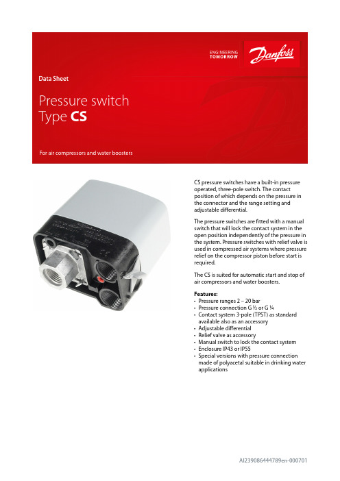
CS pressure switches have a built-in pressure operated, three-pole switch. The contact position of which depends on the pressure in the connector and the range setting and adjustable differential.The pressure switches are fitted with a manual switch that will lock the contact system in the open position independently of the pressure in the system. Pressure switches with relief valve is used in compressed air systems where pressure relief on the compressor piston before start is required.The CS is suited for automatic start and stop of air compressors and water boosters.Features:•Pressure ranges 2 – 20 bar•Pressure connection G ½ or G ¼•Contact system 3-pole (TPST) as standard available also as an accessory •Adjustable differential •Relief valve as accessory•Manual switch to lock the contact system •Enclosure IP43 or IP55•Special versions with pressure connection made of polyacetal suitable in drinking waterapplications1 2 3 4 5 6 7 8 910111213141516171819202122232425FunctionFigure 1: Design and function Danfoss31E58Slide ringEarth screw Cover screw CoverSpindleToggle armSnap springSnap armSwitch housing assy Self-tapping screwManual switchBaseGrubscrewStop pressure screwPressure padSpring retainerCompression springPressure shoeDiaphragmFlange, G ¼ or G ½CapDifferential armTension springDifferential pressure screwBracketThe pressure switch is built up of the following main elements: connector, diaphragm, snap system, main spring, differential spring and a 3-pole or one-pole contact system. The stop pressure must be set on the main spring and the difference between start and stop pressures on the differential spring.Pressure from the controlled system is led, via the connector, to the diaphragm. The diaphragm converts this pressure to a mechanical movement which is transferred by the snap system to the contact system. In this way, the contact system starts or stops a compressor/pump.Pressure switch, Type CSTechnical data(1)For water and seawater, max. 80 °C Figure 2: Resonance frequencySetting1.2.3.Figure 5: Installation Figure 6: Installationd > 8.5 mm – 1d ≤ 8.5 mm – 2031E0293turns, i.e. 4.5.InstallationRecommended orientationThe pressure switches will operate regardless of their orientation. However, to meet the enclosure requirements of IP43 and IP55, they must be mounted vertically with the connection downwards. The CS pressure switches are self-supporting (on the connection).Fitting a pressure relief valve:Remove the blanking plug Fit the pressure relief valve Fit the plastoform screwFitting screwed cable entriesThe accessory bag contains two sets of metal gaskets each with different internal diameters. These will give a sufficient cord relief if used correctly with the cable diameter concerned.Drain holeIf because of large temperature variations there is a risk of condensate forming in the pressure switch, a screwdriver can be used to make a drain hole in the enclosure.Figure 7: Drain holeDimensions [mm] and weights [kg]Figure 11: Dimensions [mm]Weight approx. 0.5 kgMains connectionFigure 12: 3-pole AC load Figure 13: 1-pole AC load Figure 14: 1-pole DC load(1)Preferred versionsAccessories and spare partsCertificates, declarations, and approvalsThe list contains all certificates, declarations, and approvals for this product type. Individual code number may have some or all of these approvals, and certain local approvals may not appear on the list.Some approvals may change over time. You can check the most current status at or contact your local Danfoss representative if you have any questions.Danfoss can accept no responsibility for possible errors in catalogues, brochures and other printed material. Danfoss reserves the right to alter its products without notice. This also applies to products already on order provided that such alterations can be made without subsequentialchanges being necessary in specifications already agreed. All trademarks in this material are property of the respective companies. Danfoss and the Danfoss logotype are trademarks of Danfoss A/S. All rights reserved.Online supportDanfoss offers a wide range of support along with our products, including digital product information, software,mobile apps, and expert guidance. See the possibilities below.The Danfoss Product StoreThe Danfoss Product Store is your one-stop shop for everything product related—no matter where you are in the world or what area of the cooling industry you work in. Get quick access to essential information like product specs, code numbers, technical documentation, certifications, accessories,and more.Start browsing at .Find technical documentationFind the technical documentation you need to get your project up and running. Get direct access to our official collection of data sheets, certificates and declarations, manuals and guides, 3D models and drawings, case stories, brochures, and much more.Start searching now at /en/service-and-support/documentation .Danfoss LearningDanfoss Learning is a free online learning platform. It features courses and materials specifically designed to help engineers, installers, service technicians, and wholesalers better understand the products, applications, industry topics, and trends that will help you do your job better.Create your Danfoss Learning account for free at /en/service-and-support/learning .Get local information and supportLocal Danfoss websites are the main sources for help and information about our company andproducts. Find product availability, get the latest regional news, or connect with a nearby expert—all in your own language.Find your local Danfoss website here: /en/choose-region .。
施耐德电气 电磁式接近开关 NBK-R系列 使用手册说明书

Operating InstructionsforLimit switchModel: NBK-RNBK-RMNBK-RTNBK-RANBK-R...1. Contents1.Contents (2)2.Note (3)3.Instrument Inspection (3)4.Regulation Use (4)4.1Electrical limit switch (4)5.Operating Principle (5)6.Mechanical Connection (6)7.Electrical Connection (7)missioning (8)9.Technical Information (9)10.Order Codes (10)11.Illustrations (11)12.Disposal (12)13.EU Declaration of Conformance (13)14.Type Examination Certificate (14)Manufactured and sold by:Kobold Messring GmbHNordring 22-24D-65719 HofheimTel.: +49 (0)6192-2990Fax: +49(0)6192-23398E-Mail:******************Internet: page 2 NBK-R... K09/0722NBK-R...2. NotePlease read these operating instructions before unpacking and putting the unitinto operation. Follow the instructions precisely as described herein.The instruction manuals on our website are always for currentlymanufactured version of our products. Due to technical changes, the instructionmanuals available online may not always correspond to the product version youhave purchased. If you need an instruction manual that corresponds to thepurchased product version, you can request it from us free of charge by email(******************)inPDFformat,specifyingtherelevantinvoicenumberandserial number. If you wish, the operating instructions can also be sent to you bypost in paper form against an applicable postage fee.The devices are only to be used, maintained and serviced by persons familiarwith these operating instructions and in accordance with local regulationsapplying to Health & Safety and prevention of accidents.When used in machines, the measuring unit should be used only when themachines fulfil the EC-machine guidelines.3. Instrument InspectionInstruments are inspected before shipping and sent out in perfect condition.Should damage to a device be visible, we recommend a thorough inspection ofthe delivery packaging. In case of damage, please inform your parcel service /forwarding agent immediately, since they are responsible for damages duringtransit.Scope of delivery:The standard delivery includes:•Electrical Limit Switches Model: NBK-R, NBK-RM, NBK-RT or NBK-RANBK-R... K09/0722 page 3NBK-R...page 4 NBK-R... K09/07224. Regulation UseAny use of the device which exceeds the manufacturer’s specification may invalidate its warranty. Therefore, any resulting damage is not the responsibility of the manufacturer. The user assumes all risk for such usage.The Limit Switches for the NBK Bypass Level Indicators are used for continuos measuring, display and monitoring of liquids in tanks or vessels. Depending on the design the limit switches are suitable for applications with a higher operating temperature or for the use in hazardous areas.4.1 Electrical limit switch- For standard applications NBK-R/NBK-RM: Bistable changeover contact fitted ina polycarbonate housing with 3m connection cable- For high temperature applications NBK-RT200/-RT400: Bistable changeovercontact fitted in an aluminium die cast housing with terminal connectors.- For ATEX applications NBK-RA: Bistable changeover contact as anencapsulated proximity switch fitted in metallic cast housing with 3 m connection cable.ATEX-marking for contact NBK-RA (encapsulated version): II 2G Ex mb IIC T6 / T5 Gb II 2D Ex mb IIIC IP67 T 105 °C Db→ Use the contacts appropriate and as intended.→ Make sure that only accessories are used in hazardous areas that meetall the requirements of the European directives and national legislation.The contacts NBK-RA with ATEX approval meet the requirements of category2 GD. The proximity switches with ATEX approval are used in the following zones:→ 2G in zone 1 → 3G in zone 2 → 2D in zone 21 → 3D in zone 22NBK-R...5. Operating PrincipleKobold Bypass Limit Transmitter are used for the monitoring of limit values intanks or vessels.They are firmly attached with mounting plates and ribbon clamps to the BypassLevel Indicator, model NBK, and can be moved to any position on the bypass-tube within the measuring length.The reed-contacts in the limit switches react bistable and they are switched bythe magnetic float inside the NBK tube as passing by.One or more limit switches can be mounted on the bypass.NBK-R... K09/0722 page 5NBK-R...page 6 NBK-R... K09/07226. Mechanical ConnectionNBK-R/NBK-RMMount and tighten the reed switch (NBK-R, NBK-RM and NBK-RA) - if available - on the bypass tube at the opposite side of the roller indicator with the provided ribbon clamps (ex contact: two ribbon clamps). The height of the switch contacts may be selected at will. The cable connection must point downwards. The switch must be attached close to the bypass tube. Due to technical adaptations, it may come to malfunctions, when installing new contacts in an existing plant. If the contact does not switch during the float passes by, the preassembled spacer (plastic) must be removed.NBK-RANBK-RT200/400The high temperature switch RT200/400 will be mounted to the bypass tube with the tube clip fixed at the contact housing.Thermal screeningNBK-R...NBK-R... K09/0722page 7ATEX- contactbrown blueblack 7. Electrical ConnectionLimit switch NBK-R, NBK-RM, NBK-RT, NBK-RAAttention!Observe the allowed electrical ratings for the limit switch.Maximum values NBK-RNBK-RM Standard- contact NBK-RT Hightemperature contact NBK-RAATEX-contactSwitching capacity: 60 W/VA 80 VA 45 W/VA Switching current: 1 A 1 A 0,6 A Switching voltage:230 V AC/DC250 V AC/DC230 V AC/DCInstall the switch (if available) according to the diagram and connect it to the electrical controller.When switching inductive loads, such as contactors, relays, etc., electrical limit values should not be exceeded, also temporarily by e.g. voltage peaks. The use of a contact protection relay is recommended to avoid overloading the reed contacts.Valid regulations for hazardous areas, and regulations for installation (DIN/VDE 0165), should be observed when installing the NBK level indicator in zone 1 or 2 of hazardous areas (no combustible liquids).Note to NBK-RA:Protect the circuit of the limit contact with a fuse. This fuse must tolerate the permitted nominal current of the switching contact and must have a deactivating ability according to the possible short circuit current of the power system at the place of installation. The contact is activated by the North Pole of a magnet and deactivated by its South Pole.NBK-RANBK-RTNBK-R NBK-RMNBK-R...page 8 NBK-R... K09/07228. CommissioningCommissioning of the electrical reed switchFunction of switchesAll switches have three connection poles (black (2), blue (3) and brown (1)).The black wire (2) is the common pole for both switching functions (N/C and N/O contact).The float must pass the switch once in both directions so that the switching func-tion is in line with the terminal connection diagram and table below.These instructions are often ignored when an alarm lamp is connected directly with the result that the alarm lamp incorrectly indicates a fault.When the switch has been passed, it is ready for operation and requires no maintenance.black (2) / blue (1) black (2) / brown (3) float above open closed float below closed openHysteresisHysteresis is the difference between contact closing and opening points. A hysteresis of approximately 15 mm float travel is achieved by factory tuning of the float magnet and contact strength.NBK-R...NBK-R... K09/0722 page 99. Technical InformationLimit contacts, model NBK-R/NBK-RM Contact operation: bistable changeover contact Switching hysteresis: approximately 15 mm Max. switching capacity: 60 W/VA; 230 V AC/DC ; 1 A Contact resistance: 100 m Ω Medium temperature: max. 100 °C Ambient temperature: max. 75 °C Connection: 3 m PVC cable Housing: polycarbonate Protection: IP 67Limit contacts, model, NBK-RT200/-RT400 Contact operation: bistable changeover contact Switching hysteresis: approximately 15 mm Max. switching capacity: 80 VA; 250 V; 1 A Contact resistance: <20 m Ω Medium temperature: max. 200 °C (-RT200) / 400 °C (-RT 400) Ambient temperature: 145 °C (RT200) / 350 °C (-RT400) Connection: terminal connectors, screwed cable gland Housing: aluminium die cast housing, terminal connectors Protection: IP 65ATEX limit switch, model NBK-RA Contact operation: bistable changeover contact encapsulated Switching hysteresis: approximately 15 mm Max. switching capacity: 45 VA, 230 V AC/DC , 0,6 A Temperature class: T6 / T5 Max. medium temperature: 70 °C / 85 °C Connection: 3 m PVC cable Housing: metallic, cast (GD-ZN Al 4 Cu1) Protection:ATEX-marking: II 2G Ex mb IIC T6/T5 Gb II 2D Ex mb IIIC IP67 T 105 °C DbNBK-R...page 10 NBK-R... K09/072210. Order CodesNBK-R NBK-RMStandard limit contact (bistable changeover contact)NBK-RT200High temperature limit contact, t max 200 °CNBK-RT400High temperature limit contact, t max 400 °C11. IllustrationsNBK-R/NBK-RM NBK-RT NBK-RA12. DisposalNote!•Avoid environmental damage caused by media-contaminated parts•Dispose of the device and packaging in an environmentally friendly manner•Comply with applicable national and international disposal regulations and environmental regulations.BatteriesBatteries containing pollutants are marked with a sign consisting of a crossed-out garbage can and the chemical symbol (Cd, Hg, Li or Pb) of the heavy metal that is decisive for the classification as containing pollutants:Cd1 Hg2 Pb3 Li41. …Cd" stands for cadmium2. …Hg" stands for mercury3. …Pb" stands for lead4. …Li" stands for lithiumElectrical and electronic equipment13. EU Declaration of ConformanceWe, KOBOLD Messring GmbH, Hofheim-Ts, Germany, declare under our sole responsibility that the product:Limit Contact model: NBK-R / NBK-RM / NBK-RTto which this declaration relates is in conformity with the standards noted below: DIN EN 61010-1: 2010Safety requirements for electrical measuring, control and laboratory instruments EN 60529:2014Protection type through case (IP code)Also, the following EEC guidelines are fulfilled:2014/35/EU Low Voltage Directive2011/65/EU RoHSFurthermore, we declare that the productmodel: NBK-RA (ELOBAU 610*)to which this declaration relates is in conformity with the standards noted below: EN 60079-0:2012 General RequirementsEN 60079-18:2009 Equipment protection by encapsulation ‘m’EN 60079-26:2007 Equipment with equipment protection level (EPL) GaEC type examination test BVS 03 ATEX E 126 Xalso, the following EEC guidelines are fulfilled:2014/34/EU ATEXHofheim, 09 March 2021H. Peters M. WenzelGeneral Manager Proxy Holder14. Type Examination Certificate。
施耐德高压开关柜操作说明教学教材

深圳市机场(集团)有限公司.动力分
开关柜的操作说明
1、进入作业现场时,必须按电力安全工作规程的要求 穿戴必要的安全防护用品。
2、在开始工作前,应对照“现场设备运行状态”,并 逐项一一核查,确认后,方可开始操作。
3、严格按照电力行业工作票制度执行,要求有监护人 员到位。送电必须由专职人员执行,严禁擅自操作 开关柜,必须严格遵守电力部门的有关规程。
插入航空插头后, 柜体状态显示灯或断 路器位置便显示其所 在位置。
安全锁定后,便能 推进机构,将手车推 向试验位置。
当手车到工作位置后,摇 进手柄无法再摇动,其对应 位置显示灯或位置显示器便 显示其所在位置。
深圳市机场(集团)有限公司.动力分
开关柜手车的三个位置
➢工作位置 断路器与一次设备有联系,合闸后, 功率从母线经断路器即可传至输电线路。
深圳市机场(集团)有限公司.动力分
黄维政
施耐德高压开关柜操作说明 2012年9月
本操作说明适用于 二总配、KB1、KB2、KB3
MVnex
施耐德高压开关柜操作说明 2012年9月
深圳市机场(集团)有限公司.动力分
EV12真空断路器本体
深圳市机场(集团)有限公司.动力分
EV12真空断路器本体
➢试验位置 二次航空插头可以插在插座上,获得 电源。断路器可以进行合闸、分闸操作, 对应指示灯亮;断路器与一次设备没有 联系,可以进行各项操作,而不会对负 荷侧有任何影响,所以称为试验位置。
➢检修位置 断路器与一次设备(母线)没有联系, 失去操作电源(二次插头已经拔下), 断路器处于分闸位置。
1 6
深圳市机场(集团)有限公司.动力分
开关柜联锁装置
开关柜具有可靠的联锁装置,满足五防的要求,切实保障了操 作人员及设备的安全。
IHP施耐德时间开关说明书

IHP电子式可编程定时开关I H P 主 菜 单+++++++IHP 控制器的菜单介绍及调试说明编程“设定新程序”按OK进入后选择通道后可以进行程序的设定“查看程序”按OK 进入后可以查看以往编写的程序“修改程序”按OK 进入后可以修改以往编写的程序“删除程序”按OK 进入后可以修改以往编写的程序“结束离开”时间及日期“时间设定”按OK 进入后可以重新设置时间“日期设定”按OK 进入后可以重新设置日期“夏/秋切换” 按OK 进入后可以重新设定夏日制/冬日制切换规则“星期起始”按OK 进入后可以重新设置每周起始(例如:欧洲以星期一为每周第一天)按OK 进入后可以重新设置其相应格式“结束离开”假期“定时器”按OK 进入后可以强制使某一通道在一个特定的时间段打开或闭合(以小时为单位)“假日编程”按OK 进入后可以强制使某一通道在一个特定的时期段打开或闭合 (设置为从某一天的一个时刻开始到另一天德 一个时刻结束)“随机模式”按OK 进入后可以马上开始一个随机输出状态“结束离开”参数设置“运行时间”按OK 进入后可以查看或清除某一通道的运行时间计数器“外部输入”按OK进入后可以设置外部输入节点的类型和其控制功能“屏幕设置”按OK 进入后可以设置屏幕的显示模式一分钟或者长亮“语言设置”按OK 进入后可以设置控制器显示语言“出厂设置”按OK 进入后可以将控制器恢复为出厂模式(慎用此功能会将控制器复位须重新设置)“系统信息”按OK 进入后可以查看控制器的相关信息“结束离开”补充强制模式的使用同时按下 “-”和“+ ”键小于两秒钟可强制使“一通道”接通,再次同时按下小于两秒钟可解除强制模式,同时按下 “+”和“ok ”键小于两秒钟可强制使“二通道”接通。
同时按下 “-”和“+ ”键大于两秒钟可强制使“一通道”永久接通,再次同时按下 “-”和“+ ”键大于两秒钟可强制使“一通道”永久断开通。
同时按下 “+”和“ok ”键大于两秒钟可强制使“二通道”接通,再次同时按下 “+”和“ok ”键大于两秒钟可强制使“二通道”永久断开通。
施耐德接触器(LC1)产品技术教材 PPT

CA2-DN40...
A2 A1
CA2-DN31...
A2
A1
CA2-DN22...
A2
第2部分
大局在握 处变不惊
—大规格接触器设备介绍
Building a New Electric World
大规格接触器设备介绍
LC1B系列 CV1、CV3系列 CR1、CR3系列 LC1V、CE、CS、CG系列
接触器的工作特点 ➢通断必须是迅速和肯定的 ➢由小电流、小截面导体的控制系统控制大电流的主回路 安全、节能。 ➢无论处于断续工作制还是连续工作性,都保证相同的功能 ➢为远距离操作、多地操作,集中控制提供了条件 ➢经受所有故障电流,包括短路和过载 ➢最频繁的切换操作,其通断次数在正常情况下远远高于保护元件和隔离元件
磁吹灭弧手段:
D/F接触器一般采用直列的灭弧栅起到一定的辅助灭弧作用, 而对于更大的电流甚至直流电,B系列接触器则采用“磁吹 灭弧”的特殊手段达到很好的灭弧效果。
大规格接触器设备介绍
LC1B-750~1800A
可用于大电流直流主回路:
施耐德的所有普通交流接触器均可用于直流主回路的控制, 但需要降容使用或者串联主触点以获得较高分断能力;B系 列接触器由于具有高效灭弧手段和很高的触点灭弧电压,所 以可以直接用于大电流直流主回路控制;
CV1和CV3的区别:
CV1定位于标准负载类应用,额定容量从80~700A(AC3类),额 定电压690V; CV3定位于重负荷负载类应用,额定容量从80~1800A(AC3类), 额定电压1000V,并且可以运用于AC4和AC5类负载。
大规格接触器设备介绍
CR1F、CR1B电磁闭锁接触器
电磁闭锁接触器:
大规格接触器设备介绍
施耐德电气操作说明书-00-00

施耐德触摸屏说 明 及 操 作 手 册使用该设备前请务必仔细阅读本说明书柳州富达机械有限公司LIUZHOU TECH MACHINERY CO., LTDCode 2205 6010 41 Edition 7/2009柳州富达机械有限公司公司地址:柳州市阳和工业新区工业园,B-22-1,B-23-1 邮编:545006 商务部电话:(0772)3171004 3172024 3172648 3172248售后服务电话:(0772)3172247 3173004技术部电话:(0772)3171256 3171564传 真:(0772)3171027网 址:E-mail:fudalz@ liutech@授权及服务中心如果机器需要停机或者没有正常运行,请关闭机器但不要试图去修理他。
请联系一个拥有授权的服务中心来修理,并且需要采用原配件。
对本建议的疏忽将会对压缩机设备的安全造成损坏。
说 明请妥善保存本说明书,以便随时查用;本手册是该机器的一部分。
请您务必在使用本机器之前详细阅读本说明书。
.对设备进行的安装以及随后的操作都必须充分地考虑到电气设备的操作规定及个人安全因素。
性能和安全说明当需要对机器进行维修的时候应先停机。
即使是小的操作也需要由拥有资格的技术人员来进行。
制造商对任何因违反本手册所造成的损失不负任何责任。
本设备不允许安装在户外。
施耐德触摸屏XBT RT500操作说明一、本说明书仅适用于使用施耐德触摸屏XBT RT500的螺杆压缩机。
XBT RT500的操作为触摸+按键相结合的形式:二、运行参数的显示在该页面上,可翻看压缩机的各种状态信息。
三、参数的设定在运行参数显示页面,按下F2按键,可进入参数设定页面。
该页面有三个选项,通过三个触摸箭头分别进入。
通过返回箭头会到参数显示页面。
1、压力传感器调零在机器开动前,要对压力传感器调零。
通过两边的触摸按键,使压力传感器显示的压力在零压状态下显示为零。
2、运行参数的设定,该项参数不需密码3、保护参数的设定在进入设定前,必需输入密码。
施耐德电气-ISE35型数字压力开关使用说明书
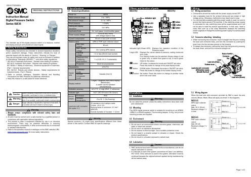
Instruction Manual Digital Pressure Switch Series ISE35The intended use of this digital pressure switch is to measure, monitor and display pressure and provide an output signal.These safety instructions are intended to prevent hazardous situations and/or equipment damage. These instructions indicate the level of potential hazard with the labels of “Caution,” “Warning” or “Danger.”They are all important notes for safety and must be followed in addition to International Standards (ISO/IEC) *1), and other safety regulations. *1)ISO 4414: Pneumatic fluid power - General rules relating to systems. ISO 4413: Hydraulic fluid power - General rules relating to systems.IEC 60204-1: Safety of machinery - Electrical equipment of machines. (Part 1: General requirements)ISO 10218-1: Robots and robotic devices - Safety requirements for industrial robots - Part 1: Robots.• Refer to product catalogue, Operation Manual and Handling Precautions for SMC Products for additional information. • Keep this manual in a safe place for future reference.CautionCaution indicates a hazard with a low level of risk which, if not avoided, could result in minor or moderate injury.WarningWarning indicates a hazard with a medium level of riskwhich, if not avoided, could result in death or serious injury.DangerDanger indicates a hazard with a high level of risk which, ifnot avoided, will result in death or serious injury.Warning• Always ensure compliance with relevant safety laws and standards.•All work must be carried out in a safe manner by a qualified person in compliance with applicable national regulations.• This product is class A equipment intended for use in an industrial environment. There may be potential difficulties in ensuringelectromagnetic compatibility in other environments due to conducted or radiated disturbances.• Refer to the operation manual or catalogue on the SMC website (URL: https:// ) for more safety instructions.2 Specifications2.1 General specificationsWarningSpecial products (-X) might have specifications different from those shown in this section. Contact SMC for specific drawings.Indication light (Green LED): Displays the operation condition of thePressure switch.3-digit LED: Displays the current status of pressure, setting mode anderror code.Four display modes can be selected: display always in red or green only, or switch from green to red, or red to green linked to the output. UP button: Increases the mode and ON/OFF set value.Press this button to change to the peak display mode. DOWN button: Decreases the mode or ON/OFF set value.Press this button to change to the bottom display mode. and to set a set value.4 Installation4.1 InstallationWarningDo not install the product unless the safety instructions have been read and understood.4.2 MountingThe ISE35 digital pressure switch is suitable for mounting on an ARM10 / ARM11 or AR/AW regulator. The mounting adapter, O-ring, lock pin and mounting screws are supplied.4.3 EnvironmentWarning• Do not use in an environment where corrosive gases, chemicals, salt water or steam are present.• Do not use in an explosive atmosphere.• Do not expose to direct sunlight. Use a suitable protective cover.• Do not install in a location subject to vibration or impact. Check the product specifications.• Do not mount in a location exposed to radiant heat.4.4 LubricationCaution• SMC products have been lubricated for life at manufacture, and do not require lubrication in service.• If a lubricant is used in the system, use turbine oil Class 1 (no additive), ISO VG32. Once lubricant is used in the system, lubrication must be continued because the original lubricant applied during manufacturing will be washed away.5 Wiring5.1 Wiring connections• Connections should be made with the power supply turned OFF.• Use a separate route for the product wiring and any power or high voltage wiring. Otherwise, malfunction may result due to noise.• If a commercially available switching power supply is used, be sure to ground the frame ground (FG) terminal. If the switching power supply is connected for use, switching noise will be superimposed and it will not be able to meet the product specifications. In that case, insert a noise filter such as a line noise filter/ferrite between the switching power supplies or change the switching power supply to a series power supply.5.2 Connector attaching / detaching• When connecting the connector, insert it straight onto the pins, holding the lever and connector body, and lock the connector by pushing the lever hook into the concave groove on the housing.• To detach the connector, remove the hook from the groove by pressing the lever down, and pull the connector straight out.5.3 Wiring diagramWhen the lead wire with connector provided by SMC is used, the wire colours (Brown, Black, Blue) will apply as shown in the diagrams. ISE35-25NPN open collector outputMax. 30 V, 80 mA Residual voltage 1 V or lessISE35-65PNP open collector outputMax. 80 mAResidual voltage 1 V or lessORIGINAL INSTRUCTIONSModel No.ISE35 Rated pressure range0 to 1 MPa Set pressure range-0.1 to 1 MPa Proof pressure 1.5 MPa Setting and display resolution 0.01 MPaApplicable fluidsAir, inert gases, incombustible gasesPower supply voltage 12 to 24 VDC ±10% with voltage ripple or less Current consumption 55 mA or less (with no load) Switch output NPN or PNP open collector outputMax. load current80 mAMax. applied voltage 30 V (during NPN output) Residual voltage1 V or less (80 mA load current) Response time Chattering-proof function 1 s (0.25, 0.5, 2, 3 selectable)Protection Short circuit protectionRepeatability±1% F.S.Hyster esisHysteresis mode Variable (from 0)Window comparator modeDisplay method 3-digits 7-segment dual-colour display(Red/Green),A switch can be operatedsimultaneously. Indication accuracy±2% F.S. ±1 digit (25±3 °C reference) Indicator light OUT: LED ON when ON (Green)Enviro nmentEnclosure IP40Ambient temperature-5 to 50 °C (No freezing)Lead wire with connector(for option "L")Oil resistance vinyl cabtyre cable 3 cores φ3.4, 2 mSectional area of conductor: 0.2 mm 2 (AWG25)Outside diameter of insulator: 1.12 mmOperationWhen the pressure exceeds the set value, the switch will turn ON.When the pressure falls below the set value by amount of hysteresis or more, the switch will turn OFF.As a default setting, the Pressure switch is set to turn ON when the pressure exceeds 0.35 MPa and turn OFF when it is below 0.34 MPa. If the operation shown below does not cause any problem, keep this setting.Setting1. Press the SET button in measurement mode to display set values.2. Press the UP or DOWN button to change the set value.The UP button is to increase and the DOWN button is to decrease.• Press the UP button once to increase by one digit and press it continuously to keep increasing the set digit.• Press the DOWN button once to decrease by one digit and press it continuously to keep decreasing the set figure. 3. Press the SET button to finish the setting.For setting in window comparator mode, refer to the operation manual on the SMC website (URL: https:// ).7.1 Default settingAt the time of shipment, the following settings are provided. If this setting is acceptable, keep it for use.If a different setting is required, change the setting.When the default setting is changed, since the different setting items appear in order depending on how many times the SET button is pressed, check that the item which needs to be set appears correctly to prevent undesired settings.Measurement mode is the condition in which the pressure is detected and displayed, and the switch function is operating.This is the basic operating mode; other modes should be selected for set-point changes and function setting.9 Other Settings• Power saving mode • Security code inputFor further details refer to the operation manual on the SMC website (URL: https:// ).10 How to OrderRefer to the operation manual on the SMC website (URL: https:// ) for How to order information.11 Outline DimensionsRefer to the operation manual or catalogue on the SMC website (URL: https:// ) for Outline Dimensions.12 Error indication13.1 General MaintenanceCaution• Not following proper maintenance procedures could cause the product to malfunction and lead to equipment damage.• If handled improperly, compressed air can be dangerous.• Maintenance of pneumatic systems should be performed only by qualified personnel.• Before performing maintenance, turn off the power supply and be sure to cut off the supply pressure. Confirm that the air is released to atmosphere.• After installation and maintenance, apply operating pressure and power to the equipment and perform appropriate functional and leakage tests to make sure the equipment is installed correctly.• If any electrical connections are disturbed during maintenance, ensure they are reconnected correctly and safety checks are carried out as required to ensure continued compliance with applicable national regulations.• Do not make any modification to the product.• Do not disassemble the product, unless required by installation or maintenance instructions.How to reset the product for power cut or forcible de-energizing The setting of the product will be retained as it was before a power cut or de-energizing.The output condition is also basically recovered to that before a power cut or de-energizing, but may change depending on the operating environment. Therefore, check the safety of the whole facility before operating the product.If the facility is under accurate control, wait until it has warmed up. (approximately 20 to 30 minutes).Mounting on the regulator• Cut the power supply to the Pressure switch when assembling. • Turn the set pressure of the regulator to zero.• Mount an O-ring into the O-ring groove of the regulator. Attention should be taken not to damage the O-ring. • Mount the adapter using 2 set screws.Recommended tightening torque: Modular AR/AW series0.6 ±0.05 N•m ARM10/11 series0.32 ±0.03 N•m• Mount the Pressure switch.• Insert the lock pin into the adapter to the end firmly. • Supply pressure slowly and ensure no air leaks.• The Pressure switch can be assembled rotated 180 degrees.14.1 Limited warranty and Disclaimer/Compliance Requirements Refer to Handling Precautions for SMC Products.Caution• SMC products are not intended for use as instruments for legal metrology.Measurement instruments that SMC manufactures or sells have not been qualified by type approval tests relevant to the metrology (measurement) laws of each country.Therefore, SMC products cannot be used for business or certification ordained by the metrology (measurement) laws of each country.15 Product disposalThis product shall not be disposed of as municipal waste. Check your local regulations and guidelines to dispose of this product correctly, in order to reduce the impact on human health and the environment.16 ContactsRefer to or www.smc.eu for your local distributor / importer.URL: https:// (Global) https://www.smc.eu (Europe) SMC Corporation, 4-14-1, Sotokanda, Chiyoda-ku, Tokyo 101-0021, Japan Specifications are subject to change without prior notice from the manufacturer. © 2021 SMC Corporation All Rights Reserved. Template DKP50047-F-085M。
施耐德PLC教程 ppt课件
2020/12/15
12
第八章 TWIDO PLC常见故障诊断
目录
8.1 CPU、I/O模块各指示灯的含义 8.2 系统位、系统字中的错误代码
2020/12/15
13
附录 1 TWIDO PLC的模块接线图
2020/12/15
7
第四章 基本编程指令
目录
4.4 程序指令 END 指令 NOP指令 跳转指令 子程序指令
4.5 浮点指令 浮点算术指令 三角指令 转换指令 整数转换指令<-> 浮点
2020/12/15
8
第五章 TWIDOSOFT编程软件
目录
5.1 安装TWIDOSOFT软件 5.2 启动TWIDOSOFT软件
目录
1、安装方法 2、CPU模块接线图 3、离散量I/O模块接线图 4、模拟量I/O模块接线图 5、外部电池安装方法
2020/12/15
14
TWIDO PLC 高级教程
目录
1.1 宏功能的应用 1.1.1 一般COMM通讯 1.1.2 变频器DRIVER通讯
1.2 CANOPEN通讯介绍 1.2.1 CANOPEN配置工具的用法 1.2.2 CANOPEN的编程方法
编程设备(可选)
I/O I/O
存储器(系统 /用户程序)
输
输
入
出
处理器CPU
接
接
口
口
电源
2020/12/15
18
1.3 可编程控制器的工作原理 •1.3.1 扫描原理 •1.3.2 I/O映象区,响应时间 •1.3.3 举例说明PLC如何取代传统的继电器、接触器控制电路
施耐德万高ATMT说明书

ATMT自动电源转换系统用户手册下面的符号将用于本手册的说明,提醒您注意潜在的危险,或者请您注意那些阐述、简化过程和关键操作。
开关的不可恢复性损坏。
X: 关键性操作,提示您使用不当时,可能使控制器工作于非正常状态。
请注意:电气设备应该让有资格的专业人员进行安装、操作、使用、维护。
未按使用手册操作而造成的不良后果,施耐德电气公司将不负任何责任。
目录一、控制器介绍 (1)1. 符合标准 (1)2. 污染等级 (1)3. 抗湿热等级 (1)4. 电磁兼容性 (1)5. 安装与操作指南 (1)6. 安全信息 (1)7. 控制器类型 (1)二、控制器操作及参数设置 (3)1. 2A/2B控制器面板介绍 (3)2. 3A/3B控制器面板介绍 (4)3. 显示及设置 (5)三、控制器端子说明 (11)四、安装及接线 (12)1. 控制器外形及安装尺寸 (12)2. 适配器外形及安装尺寸 (13)3. 适配器与开关接线图 (15)4. 2A/2B整体安装图 (16)5. 3A/3B整体安装图 (17)一、控制器介绍1.符合标准•GB14048.1-2006 低压开关设备和控制设备:总则•GB14048. 2-2008 低压开关设备和控制设备:断路器•GB/T14048.11-2008 低压开关设备和控制设备:多功能电器转换开关电器•IEC60947:2005 Low-voltage switchgear and controlgear•IEC60947-2:2005 Low-voltage switchgear and controlgear: Breakers•IEC60947-6-1:2005 Low-voltage switchgear and controlgear: Multiple function equipment- Transfer switching equipment2.污染等级•Level33.抗湿热等级A TMT已通过下列标准所规定的严格环境条件下的试验•IEC60068-2-1 干冷环境(-5℃)•IEC60068-2-1 干热环境(+40℃)•IEC60068-2 低温4.电磁兼容性•辐射等级B级执行标准GB4824(CISPR11)•静电放电空气放电Level3;接触放电Level2 执行标准GB1 7626.2-2006(IEC61000-4-2)•射频电磁场LE VEL3 执行标准GB1 7626. 3-2006 (IEC61000-4-3)和GB1 7626.6-2006 (IEC61000-4-6)•电快速瞬变脉冲群LE VEL3 执行标准GB1 7626.4-2008 (IEC61000-4-4)•浪涌LE VEL3 执行标准GB1 7626. 5-2008 (IEC61000-4-5)5.安装与操作指南即使控制单元处于待机状态,在手动操作断路器前需要将其断电,它可能在没有任何警告的情况下操作断路器。
施耐德开关柜基础知识培训PPT课件

主要劣势
只有前出线没有后出线
安装密度小(30)
柜中不同方案不能混装
垂直母线带电时功能单元的更换能力差
水平母线柜间搭接需开孔,不可现场升级
没有自带的专用托盘
主要竞争对手3: MNS3.0
• 1999年推出最新的MNS3.0智能型低压开关柜 • 型号含义
柜体的安装方式
母线的分类:
配电 母线
➢主母线(水平母线): 连接一条或几条配电母线和或进线和出线单元的母线
➢配电母线(垂直母线): 框架单元内的一条,它连接在主母线上,并由它向出 线单元供电
主母线
母线的基本要素:
➢母线的额定电流及规格: 母线的载流量及横截面
➢母线的短时耐受电流 母线在短路时动热稳定所能承受的最大电流有效值
抽出式 断路器
下进线
固定式功 能单元 配电回路
平面布置图简介
主母线
配电母线 即垂直母线
抽屉功能单元 马达回路
PC柜
MCC柜 MCC柜 MCC柜
下出线
柜体
母线 功能单元
低压开关柜技术协议表
制造及验收标准 污染等级 额定工作电压 额定绝缘电压 外形尺寸(长x宽x深)及柜型 外壳颜色及表面处理 外壳防护等级 联拼方式 进线方式 出线方式 柜内分割方式 母线系统接地型式 主母线额定电流(A) 主母线短时耐受电流有效值/峰值(KA) 主母线规格 主母线表面处理 配电母线额定电流(A) 配电母线短时耐受电流有效值/峰值(KA) 配电母线规格 配电母线表面处理
□上进 □ 下进 □侧进 其他_____
□上出 □ 下出 其他_____
□形式2 □形式3 □形式4 其他_____
讲解施耐德按钮教材

第二部分:XB2-E经济型系列按 钮和指示灯型号含义
121:按钮第一位:1-系列号 第二位:颜色 2-黑 3-绿 4-红 第三位:触点类型 1-常开 2-常闭 5-常开+常闭 XB2-BVM1C XB2-B:XB2-B系列指示灯 V:指示灯 M: D-灯泡BA9S不提供〈380V,50HZ B-带LED灯 24C AC/DC M-带LED灯 220V 50HZ
第三部分:怎样拆分、换触点、 换盖子
最特殊的一个型号为 XB2-BS542C 可以拆分为:ZB2-BS54C+ZB2-BZ102 换盖子: 这个主要是钟对指示灯、带灯按钮。
结束!
讲解人: 日期:
金属型系列按钮机构形式:
ZB2-BZ106:1常开(先通后断)+1常闭 ZB2-BZ107:1常开(先断后通)+1常开 ZB2-BE系列 ZB2-BE101:1常开 ZB2-BE102:1常闭 颜色有:1、白色 2、黑色 3、绿色 4、 红色 5、黄色 6、蓝色 7、透明
第二部分:XB2-E经济型系列按 钮和指示灯型号含义
XB2-E A 121 XB2-E:XB2-E经济型系列按钮和指示灯 A:V为指示灯/A为按钮 121:指示灯第一位:1-白炽灯 2-氖灯 第二位:3-130V,50HZ,带灯泡 6-小于或等于250V,50HZ, 不带灯泡 4-230V,50HZ,带灯泡 5-380V,50HZ,带灯泡 第三位:3-绿 4-红 5-黄 6-蓝
金属型系列按钮机构形式:
A:平头按钮 C:蘑菇头弹簧复位按钮 D:选择按钮(标准手柄) G:选择按钮(带钥匙) J:选择按钮(长手柄) L:凸头按钮 P:带罩按钮 R:蘑菇头弹簧复位按钮 S:急停按钮(钥匙释放或旋转释放) T:急停按钮(拉力释放)
- 1、下载文档前请自行甄别文档内容的完整性,平台不提供额外的编辑、内容补充、找答案等附加服务。
- 2、"仅部分预览"的文档,不可在线预览部分如存在完整性等问题,可反馈申请退款(可完整预览的文档不适用该条件!)。
- 3、如文档侵犯您的权益,请联系客服反馈,我们会尽快为您处理(人工客服工作时间:9:00-18:30)。
金属型系列按钮机构形式:
ZB2-BZ106:1常开(先通后断)+1常闭 ZB2-BZ107:1常开(先断后通)+1常开 ZB2-BE系列 ZB2-BE101:1常开 ZB2-BE102:1常闭 颜色有: 1 、白色 2 、黑色 3 、绿色 4 、 红色 5、黄色 6、蓝色 7、透明
第二部分:XB2-E经济型系列按 钮和指示灯型号含义
第三部分:怎样拆分、换触点、 换盖子
XB2-BD21C=ZB2-BD2C+ZB2-BZ101C 同样的还有 XB2-BG 、 XB2-BJ 、 XB2-BP 、 XB2-BA等系列 XB2-BW31B1C至XB2-BW36B1C XB2-BW31B1C=ZB2-BWB11C+ZB2- BW31C XB2-BW31M1C至XB2-BW36M1C XB2-BW31M1C=ZB2-BWM11C+ZB2-BW31C XB2-BW3461C=ZB2-BW34C+ZB2-BW061C
XB2-E A 121 XB2-E:XB2-E经济型系列按钮和指示灯 A:V为指示灯/A为按钮 121:指示灯第一位:1-白炽灯 2-氖灯 第二位:3-130V,50HZ,带灯泡 6- 小于或等于 250V , 50HZ , 不带灯泡 4-230V,50HZ,带灯泡 5-380V,50HZ,带灯泡 第三位:3-绿 4-红 5-黄 6-蓝
第三部分:怎样拆分、换触点、 换盖子
最特殊的一个型号为 XB2-BS542C 可以拆分为:ZB2-BS54C+ZB2-BZ102 换盖子: 这个主要是钟对指示灯、带灯按钮。
结束!
讲解人: 日期:
Байду номын сангаас
第二部分:XB2-E经济型系列按 钮和指示灯型号含义
121:按钮第一位:1-系列号 第二位:颜色 2-黑 3-绿 4-红 第三位:触点类型 1- 常开 2- 常闭 5-常开+常闭 XB2-BVM1C XB2-B:XB2-B系列指示灯 V:指示灯 M: D-灯泡BA9S不提供〈380V,50HZ B-带LED灯 24C AC/DC M-带LED灯 220V 50HZ
金属型系列按钮机构形式:
A:平头按钮 C:蘑菇头弹簧复位按钮 D:选择按钮(标准手柄) G:选择按钮(带钥匙) J:选择按钮(长手柄) L:凸头按钮 P:带罩按钮 R:蘑菇头弹簧复位按钮 S:急停按钮(钥匙释放或旋转释放) T:急停按钮(拉力释放)
金属型系列按钮机构形式:
X:急停按钮(拉力释放) W:带指示灯的按钮 E:触点模块 Z:触点模块(带安装固定块) ZB2-BZ系列 ZB2-BZ101:1常开 ZB2-BZ102:1常闭 ZB2-BZ103:2常开 ZB2-BZ104:2常闭 ZB2-BZ105:1常开+1常闭
讲解施耐德按钮教材
介绍
介绍按钮的作用 介绍按钮的类型
第一部分:XB2-B金属型系列按 钮和指示灯型号含义
按钮有以下的几种系列: XB2( 直径为 22MM);XB4( 直 径 为 16MM);XB6 等 。 施 耐 德按钮的组成是由一个头一个座。触点 可以灵活运用。在一个基座上最多只可 以装6个触点。 ZB2-B 系 列 按 钮 ( 最 常 用 的 是 直 径 为 22MM的)
