产品说明书(Specification)
SPECIFICATIONS 产品说明书

SPEC19-08 10/15)Outlet: 1-1/4” tube outlet for 1-1/4” slip joint connectionACCESS PANELSHeavy-gauge steel with vandal-resistant screws. Provides access for easy hook-up of all plumbing connections. SUGGESTED SPECIFICATIONSUnit shall include powder-coated finish with vandal-resistant pushbutton actuation, vandal-resistant bubbler with integral hood guard, and contour-formed rounded basin to reduce splash and prevent standing water. Fountain shall comply with ANSI 117:1 and ADA for visual and motion disabilities. The manufacturer shall certify the unit to meet the requirements of NSF/ANSI 61, and the Safe Drinking Water Act.Outdoor TubularModel LK4410FRK is shown.2222 Camden Court Oak Brook, IL In keeping with our policy of continuing product improvement, Elkay reserves the right to change specification without notice. Please visit for the most current version.ModelColor OptionADA CompliantNSF/ANSI 61CertifiedLK4410FRK*(Refer to Finish Color Options)••* Select color option to complete model number. Example: LK4410FRK EVG Beige Black Blue Brown Evergreen GrayOrange Purple Terracotta Red White YellowN o w Av a i l a bl ei n12Co l o r s !Each 4410 FR consists of 2 cartons of the following:• Fountain• Single Freeze-Resistant Valve System - 97243CThis specification describes an Elkay product with design, quality and functional benefits to the user. When making a comparison of other producer’s offerings, be certain these features are not overlooked.FINISH COLOR OPTIONS – Choose color option to complete your model number, add as suffix example: LK4410FRK EVGMatte finish: Evergreen = EVG Gloss finish: Beige = BGE Gray = GRY Terracotta = TER Black = BLK Orange = ORN White = WHT Blue = BLU Purple = PUR Yellow = YLWBrown = BRN Red = REDOPTIONS• Hose Bib (Locking) - LK4471LHB * (Choose color option to complete your model number)• Hose Bib (Non-Locking) - LK4470NLHB* (Choose coloroption to complete your model number)• Direct Bury Kit - 97890CPrinted in the U.S.A.Page 2MODEL LK4410FRK Outdoor TubularFreeze-Resistant FountainOPERATING PRESSURES:Supply water 20 – 105 psi maximumMOUNTING INSTRUCTIONS and PLUMBING INSTRUCTIONSSite and drainage excavation is required for fountain installation. Refer to owner’s manual for site preparation details. Provide solid, well-drained surface to mount pedestal fountain (concrete pad recommended) with adequate support (300 lb. load minimum). (6) 3/8” minimum fasteners (not included) should be attached securely to mounting surface in order to secure fountain, (Refer to rough-in diagram), and be sure to allow an opening for the freeze-resistant valve in the ground as shown in the diagram below). Refer to local codes for any additional requirements.Locate and install plumbing through ground as required. Assemble fountain to prepared site and mounting pad.NOTE: Fountain is not furnished with service valve.Position pedestal over plumbing and secure base to fasteners. Remove access panels and connect supply and water lines. Turn on water supply and check for leaks. Refer to owner’s manual for detailed instructions.Reassemble access panels to pedestal. Trap and service stop not included.2222 Camden Court Oak Brook, IL 。
聚合物锂离子电池产品规格书说明书

Product Specification for Li-ion Polymer Battery 聚合物锂离子电池产品规格书Model电芯型号: 702427(PCM)惠州基安比新能源有限公司HUIZHOU MARKYN NEW ENERGY CO.,LTD.电话: ************传真: ************TEL: ************ FAX : ************SPECIFICATION AMENDMENT RECORDS规格书变更记录1. Scope适用范围:This document describes the Product Specification of the Li-Polymer Rechargeable Battery supplied by Huizhou Markyn New Energy Co., LTD.本规格书描述了惠州基安比新能源有限公司的可充电锂离子聚合物电池的产品性能指标。
2. Description 说明2.1 Description: Li-Polymer Battery类型:锂离子聚合物电池2.2 Model: 702427型号:7024273. Specification产品规格4. Battery Cell Performance Criteria 电芯性能标准4.1 Standard testing environment标准测试环境Unless specifically stated otherwise, tests must be done within one month of delivery and the number of charging-recharging cycles is fewer than 5. The following is test conditions:Test conditions:Ambient Temperature:23ºC ± 2ºCAmbient Humidity:65±20%RH除非另有说明,测试应在电池出货的1个月内进行,且充放电循环的次数少于5次。
MF58-503-3950-1 热敏电阻 产品说明书
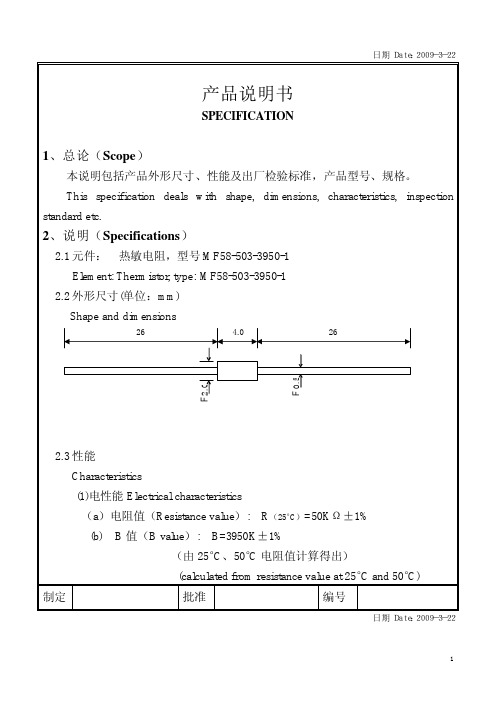
日期Date:2009-3-22 日期Date:2009-3-22 (c)绝缘电阻Insulation resistance100MΩ or over by DC500V megger (between glass and lead wire) (2) 热时间常数Thermal time constant (τ): τ≤20s (静止空气中 in still air) (3) 热耗散系数Thermal dissipation constant (δ): δ≥2.0Mw/°C (静 止空气中in still air) (4) 使用温度范围Operating temperature range:-50 ̄+260°C 3、可靠性(Reliability) 3.1高温存放 high Temp. storage:250°C环境中放置1000小时阻值变化不大于±2%。
3.2低温存放 Low Temp. storage:-40°C环境中放置1000小时阻值变化不大于±2%。
3.3耐湿热 High temperature and humidity:60°C 95%RH存放1000小时后阻值变化不大于±2%。
3.4耐温度冲击 Thermal shock:热敏电阻经历如下温度循环100次后,阻值变化不大于±2%。
-40°C10分钟----常温5分钟----200°C10分钟----常温5分钟 3.5振动Vibration:元件经受加速度10g,振幅1.5mm频率从10Hz到500Hz X、Y方向各15分钟后应无损伤,阻值变化不大于±2%。
3.6引线强度 Pulling :引线沿轴向施加9.8N拉力并持续60秒后,外观无损伤,阻值变化不大于±2%。
3.7 跌落 Fall down :从1米高度自由落下10次在规定的木板上外观无损伤,阻值变化不大于±1%。
产品说明书英文简称

Product Specification Document (PSD) IntroductionThe Product Specification Document (PSD) is a comprehensive guide that provides detailed information about a product. It serves as a reference for both technical and non-technical users, aiding in understanding the functionality, features, and usage of the product. This document outlines the essential components of the PSD and its significance in ensuring effective communication and proper usage of the product.Purpose of the PSDThe primary purpose of the PSD is to communicate essential information about the product to potential users, stakeholders, and members of the development team. It serves as a reliable source of information for various purposes, including product evaluation, support, troubleshooting, and enhancement.Components of the PSD1. Product OverviewThe Product Overview section provides a brief introduction to the product, highlighting its purpose, target audience, and key features. It provides a high-level understanding of the product and its value proposition.2. System RequirementsThe System Requirements section outlines the hardware and software prerequisites for installing and running the product. It specifies the minimum and recommended system configurations, such as processor, memory, operating system, and any additional dependencies.3. Installation GuideThe Installation Guide provides step-by-step instructions on how to install and setup the product. It includes information on acquiring the installation files, configuring the environment, and any additional steps required for proper installation.4. User ManualThe User Manual section comprises detailed instructions on how to use the product and its various features. It includes descriptions of the user interface, functionalities, and workflows. The manual may also cover customization options, settings, and troubleshooting tips.5. Product SpecificationsIn this section, detailed technical specifications of the product are provided. It includes information about architecture, design, data formats, protocols, and other technical aspects. This section is primarily intended for developers, system administrators, or individuals seeking in-depth knowledge about the product.6. Frequently Asked Questions (FAQs)The FAQs section addresses common queries and concerns related to the product. It provides answers to frequently asked questions, helping users quickly find solutions to common issues or inquiries.7. Support and Contact InformationThe Support and Contact Information section provides details on how users can seek support or assistance with the product. It includes contact information for customer support, online forums, user communities, and any available resources for obtaining help.8. Legal InformationThe Legal Information section covers any relevant legal disclaimers, licenses, copyright notices, or terms of use associated with the product. It ensures compliance with legal requirements and addresses any potential liabilities or limitations.ConclusionThe Product Specification Document (PSD) plays a crucial role in effectively communicating key information about a product. It provides a comprehensive overview, technical details, installation instructions, and support resources. By referring to the PSD, users can understand the product’s features, functionalities, system requirements, and limitations. The PSD serves as a valuable resource for users and stakeholders, promoting optimal usage and satisfaction with the product.。
MOLEX PRODUCT SPECIFICATION MICRO-FIT 产品说明书

REVISION:ECR/ECN INFORMATION: TITLE: PRODUCT SPECIFICATIONMICRO-FITDUAL ROW CONNECTORSSHEET No.M8EC No:UCP2012-13591 of 8DATE:2011/10/28DOCUMENT NUMBER: CREATED / REVISED BY:CHECKED BY:APPROVED BY:MICRO-FIT1.0 SCOPEThis Product Specification covers the 3.00 mm (.118 inch) centerline (pitch) square pin headers when mated with either printed circuit board (PCB) connector or connectors terminated with 20 to 30 AWG wire using crimp technology.2.0 PRODUCT DESCRIPTION2.1 PRODUCT NAME AND SERIES NUMBERSReceptacle: 43025 Terminal: 43030 Plug: 43020 Terminal: 43031 Headers: 43045, 44914Test Plug: 44242 (recommended for continuity testing only)Other products conforming to this specification are noted on the individual drawings.2.2 DIMENSIONS, MATERIALS, PLATINGS AND MARKINGSHousings: Receptacle and Plug - Polyester, Nylon; Headers - LCP Terminal: Phosphor Bronze Pins: Brass, Modified Tin/Brass2.3 SAFETY AGENCY APPROVALSFile Numbers: UL: E29179 CSA: LR19980 TUV: 720810373.0 APPLICABLE DOCUMENTS AND SPECIFICATIONS Test Summary: TS-43045-0014.0 RATINGS4.1 SAFETY AGENCY RATINGSSeries Agency Voltage Rating(AC RMS or DC)Agency Current Rating (Single Circuit)(Amps) UL CSA TUV UL CSA TUV 43020 350 250 250 5 7 5 43025 600 250 250 5 7 5 43045 600 250 250 5 5 5 44914600250250555(Current ratings are maximum and may vary depending on wire size, circuit count, and end-use application. Further testing may be required in the end-use application.)REVISION:ECR/ECN INFORMATION: TITLE: PRODUCT SPECIFICATIONMICRO-FITDUAL ROW CONNECTORSSHEET No.M8EC No:UCP2012-13592 of 8DATE:2011/10/28DOCUMENT NUMBER: CREATED / REVISED BY:CHECKED BY:APPROVED BY:4.2 CURRENT DERATING AND APPLICABLE WIRESCurrent is dependent on connector size, contact material, plating, ambient temperature, printed circuit board characteristics and related factors. Actual current rating is application dependent and should be evaluated for each application.AWG Max. Outside Insulation Diameter20 1.85 mm (.073 inch) 22 1.85 mm (.073 inch) 24 1.85 mm (.073 inch) 26 1.27 mm (.050 inch) 28 1.27 mm (.050 inch) 30 1.27 mm (.050 inch)CURRENT DERATING REFERENCE INFORMATIONAWG 2-circuit 6-circuit 12-circuit 24-circuit W-WW-B W-W W-B W-W W-B W-W W-B Amps Amps Amps Amps Amps Amps Amps Amps 20 6.5 7 5 * 5.5 4.5 * 5 * 4 4.5 22 5.5 * 6 * 4 * 4.5 * 3.5 * 4 * 3 * 3.5 24 5 5.5 4 * 4.5 3 * 3.5 * 2 * 3 26 4 4.5 3 * 4 2.5 * 3.5 * 1.5 2.5 28 3 * 4 * 2 * 3 * 2 * 3 * 1 * 2 3033.52* 32* 2.5* 111) Values are for REFERENCE ONLY.2) Current deratings are based on not exceeding 30°C Temperature Rise.3) PCB trace design can greatly affect temperature rise results in Wire-to-Board applications. 4) Data is for all circuits powered.5) * indicates interpolated information.6) W-W: Wire-to-Wire W-B: Wire-to-Board4.3 CURRENT FOR TEST PLUG 442422.5 Amps Maximum (Pogo pin current capacity)Test plugs are for testing purposes only and not intended for continuous use.4.4 TEMPERATUREOperating: - 40°C to + 105°C (Including Terminal Temperature Rise) Non-operating: - 40°C to + 105°CREVISION:ECR/ECN INFORMATION: TITLE: PRODUCT SPECIFICATIONMICRO-FITDUAL ROW CONNECTORSSHEET No.M8EC No:UCP2012-13593 of 8DATE:2011/10/28DOCUMENT NUMBER: CREATED / REVISED BY:CHECKED BY:APPROVED BY:5.0 PERFORMANCE5.1 ELECTRICAL REQUIREMENTSDESCRIPTION TEST CONDITIONREQUIREMENT Contact Resistance (Low Level) Mate connectors: apply a maximum voltage of 20 mV and a current of 100 mA. (Does not include wire resistance)10 milliohms MAXIMUM [initial] Contact Resistance of Wire Termination (Low Level) Terminate the applicable wire to the terminal and measure wire using a voltage of 20 mV and a current of 100 mA.5 milliohms MAXIMUM [initial] Insulation Resistance Unmate & unmount connectors: apply a voltage of 500 VDC between adjacentterminals and between terminals to ground. 1000 Megohms MINIMUM Dielectric Withstanding Voltage Unmate connectors: apply a voltage of {two times the rated voltage plus 1000 volts} VAC for 1 minute between adjacent terminals and between terminals to ground.No breakdown; current leakage < 5 mACapacitanceMeasure between adjacent terminals at 1 MHz.2 picofarads MAXIMUMTemperatureRise(via Current Cycling)Mate connectors: measure the temperature rise at the rated current after:1) 96 hours (steady state)2) 240 hours (45 minutes ON and 15minutes OFF per hour) 3) 96 hours (steady state)Temperature rise: +30°C MAXIMUM5.2 MECHANICAL REQUIREMENTSDESCRIPTION TEST CONDITIONREQUIREMENT Connector MateandUnmate Forces Mate and unmate connector (male to female) at a rate of 25 ± 6 mm (1 ± ¼ inch) per minute. (Per circuit)8.0 N (1.8 lbf)MAXIMUM insertion force&3.7 N (0.8 lbf)MINIMUM withdrawal force Terminal Retention Force (in Housing) Axial pullout force on the terminal in the housing at a rate of 25 ± 6 mm (1 ± ¼ inch) per minute.24.5 N (5.5 lbf)MINIMUM retention force Terminal Insertion Force (into Housing)Apply an axial insertion force on the terminal at a rate of 25 ± 6 mm (1 ± ¼ inch) per minute.14.7 N (3.3 lbf)MAXIMUM insertion forceREVISION: ECR/ECN INFORMATION: TITLE: PRODUCT SPECIFICATIONMICRO-FITDUAL ROW CONNECTORSSHEET No.M8EC No:UCP2012-13594 of 8DATE:2011/10/28DOCUMENT NUMBER: CREATED / REVISED BY:CHECKED BY:APPROVED BY:5.2 MECHANICAL REQUIREMENTSDurabilityMate connectors up to 30 cycles at amaximum rate of 10 cycles per minute prior to Environmental Tests.20 milliohms MAXIMUM (change from initial) Vibration (Random)Mate connectors and vibrate per EIA 364-28, test condition VII , Letter D. Test Duration: 15 minutes each axis.20 milliohms MAXIMUM (change from initial)&Discontinuity < 1 microsecond Shock (Mechanical)Mate connectors and shock at 50 g’s with ½ sine wave (11 milliseconds) shocks in the ±X,±Y,±Z axes (18 shocks total).20 milliohms MAXIMUM (change from initial])&Discontinuity < 1 microsecond WirePullout Force(Axial)(Wire from Terminal)Apply an axial pullout force on the wire at a rate of 25 ± 6 mm (1 ± ¼ inch) per minute.MINIMUM pullout force 20 awg: 57.8 N (13.0 lbf) 22 awg: 35.6 N (8.0 lbf) 24 awg: 22.2 N (5.0 lbf) 26 awg: 13.3 N (3.0 lbf) 28 awg: 8.9 N (2.0 lbf) 30 awg: 6.6 N (1.5 lbf)Normal Force Apply a perpendicular force.2.7 N (0.6 lbf) MINIMUMPin to Header RetentionApply axial push force to pin at a rate of 25 ± 6 mm (1 ± ¼ inch) per minute.13.7 N (3.1 lbf)MINIMUM pushout force Thumb Latch to Ramp Yield Strength Full mate and then Unmate the connectors at a rate of 25 ± 6 mm (1 ± ¼ inch) per minute.68.4 N (15.4 lbf) MINIMUM Yield Strength Panel Mount RetentionInsert connector in panel. Apply an axial force on the connector in the oppositedirection of insertion at a rate of 25 ± 6 mm (1 ± ¼ inch) per minute.155.7 N (35 lbf)MINIMUM pushout forceCompliant PinInsertion Force intoPCB Hole(44914 Series) Apply an axial insertion force on the terminal at a rate of 25 ± 6 mm (1 ± ¼ inch) per minute. 106.7 N (24 lbf)MAXIMUM Insertion force(Per Terminal)Compliant PinRetention Force inPCB Hole(44914 Series)Apply an axial extraction force on the terminal at a rate of 25 ± 6 mm (1 ± ¼ inch) per minute. 35.6 N (8 lbf)MINIMUM Retention force(Per Terminal)REVISION:ECR/ECN INFORMATION: TITLE: PRODUCT SPECIFICATIONMICRO-FITDUAL ROW CONNECTORSSHEET No.M8EC No:UCP2012-13595 of 8DATE:2011/10/28DOCUMENT NUMBER: CREATED / REVISED BY:CHECKED BY:APPROVED BY:5.3 ENVIRONMENTAL REQUIREMENTSDESCRIPTIONTEST CONDITIONREQUIREMENT Thermal AgingMate connectors; expose to: 240 hours at 105 ± 2°C OR500 hours at 85 ± 2°C20 milliohms MAXIMUM (change from initial])Humidity (Steady State)Mate connectors: expose to a temperature of 40 ± 2°C with a relative humidity of 90-95% for 96 hours.Note: Remove surface moisture and air dry for 1 hour prior to measurements.20 milliohms MAXIMUM (change from initial)&Dielectric WithstandingVoltage:No Breakdown at 500 VAC&Insulation Resistance: 1000 Megohms MINIMUMSolderability Per SMES-152Solder coverage: 95% MINIMUM (per SMES-152)Solder ResistanceA) Wave Solder ProcessDip connector terminal tails in solder; Solder Duration: 10 seconds MAX Solder Temperature: 260°C MAX Per ES-40000-5013B) Convection Reflow Solder Process 235°C MAX Per ES-40000-5013Parts identified with a green dot on the primary shipping carton label and all parts with a manufacturing date after 11/1/2007: 260°C MAX Per ES-40000-5013Visual:No Damage to insulatormaterialCold ResistanceMate connectors: Duration: 96 hours;Temperature: -40 ± 3°C20 milliohms MAXIMUM (change from initial)6.0 PACKAGINGParts shall be packaged to protect against damage during handling, transit and storage per the packaging specifications listed below:Receptacle and Plug: Bulk PackagedHeaders: PK-70873-0313, PK-70873-0314, PK-70873-05**.REVISION: ECR/ECN INFORMATION: TITLE: PRODUCT SPECIFICATIONMICRO-FITDUAL ROW CONNECTORSSHEET No.M8EC No:UCP2012-13597 of 8DATE:2011/10/28DOCUMENT NUMBER: CREATED / REVISED BY:CHECKED BY:APPROVED BY:8.3 STANDARD POLARIZATION FOR HEADERS AND PLUGS (HEADERS ARE SHOWN)REVISION: ECR/ECN INFORMATION: TITLE: PRODUCT SPECIFICATIONMICRO-FITDUAL ROW CONNECTORSSHEET No.M8EC No:UCP2012-13598 of 8DATE:2011/10/28DOCUMENT NUMBER: CREATED / REVISED BY:CHECKED BY:APPROVED BY:8.4 STANDARD POLARIZATION FOR RECEPTACLES。
100Ah产品规格书 100Ah Product Specification说明书
100Ah 产品规格书Product Specification of 100Ah Cell电芯型号Cell Model : 001CB270 电芯容量Cell Capacity : 100Ah修改记录目录Content0术语定义Definitions (4)1适用范围Scope of application (5)2产品电性能指标Electrical specification (5)2.1概要General (5)2.2充电模式/参数Charging/Parameter (6)2.3放电模式Discharging (7)2.4低温容量Low Temperature Capacity (7)3安全与可靠性Safety and Reliability (7)4产品寿命终止管理Product End of Life Management (7)5应用条件Application Conditions (8)6安全防范Safety Precautions (10)7免责声明Disclaimer (11)5风险警告Risk Warning (13)8电芯图纸Mechanical Drawing (15)0术语定义 Definitions术语 Terms 定义 Definition1. 适用范围 Scope of application本技术协议详细描述了CATL 生产的3.2V 100Ah 储能用磷酸铁锂电池的产品性能指标以及产品使用条件及风险警示。
The purpose of this document is to specify the specifications of 100Ah 3.2V lithium iron cells for energy storage system with CATL (“Product”) to be supplied by CATL.2. 产品电性能指标 E lectrical specification2.2.8其他充电条件(模式) C-Rate Other charge Condition (C-Rate)3.安全与可靠性 Safety and Reliability3.1使用条件说明:安全测试、寿命测试、系统成组设计需要施加预紧力,新鲜电芯的预紧力范围为2000N~5000N,全生命周期受力范围为2000N~15000N。
磷酸铁锂电池 LP90100160F 产品规格书说明书

2.8
Discharge 放电
最大放电电流 Cut-off Voltage
放电终止电压
20000 2.000±0.005
mA V
2.0C5A
Operation Charge 充电温度
0 ~ 45
℃
2.9 Temperature
工作温度 Discharge 放电温度
-10 ~ +60
℃
1 month 1 个月(贮存期)
W
Max101
L
Max166
L1
Max168
L2
10±1
M
37±1
N
20±0.5
L1 L
L2
M N+-源自WT4. Appearance 外观
It shall be free from any defects such as remarkable scratches, breaks, cracks, discoloration, leakage, or middle deformation. 电池表面无划伤、裂纹、脏点、锈蚀、变形、变色、漏液等缺陷,中间无翘起。
1C5A 放电容量
放电容量≥最小容量
High temp. discharge
Discharge Time≥54min
5.1.2 capacity 高温性能
放电时间≥54min
Low temp. discharge
Discharge Time≥3h
5.1.3 capacity 低温性能
放电时间≥3h
Test Instructions 测试方法
1
Scope…………………………………………………………………………………………………
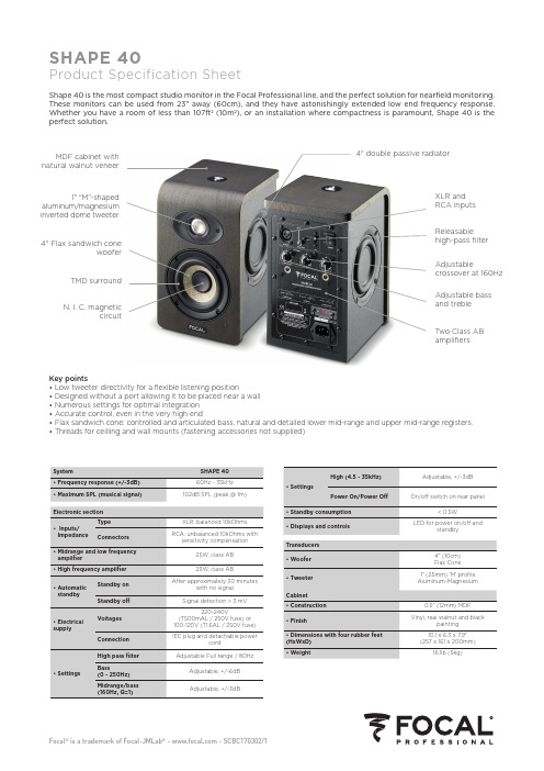
Focal Shape 40 产品说明书
SHAPE 40 60Hz - 35kHz 102dB SPL (peak @ 1m)
XLR: balanced 10kOhms RCA: unbalanced 10kOhms with
sensitivity compensation
25W, class AB
25W, class AB After approximately 30 minutes
Cabinet • Construction • Finish • Dimensions with four rubber feet (HxWxD) • Weight
Adjustable, +/-3dB
On/off switch on rear panel
< 0.5W LED for power on/off and
r
4" double passive radiator
1" “M”-shaped aluminum/magnesium inverted dome tweeter
4" Flax sandwich cone woofer
TMD surround
N. I. C. magnetic circuit
XLR and RCA inputs
Releasable high-pass filter
Adjustable crossover at 160Hz
Adjustable bass and treble
Two Class AB amplifiers
Key points • Low tweeter directivity for a flexible listening position • Designed without a port allowing it to be placed near a wall • Numerous settings for optimal integration • Accurate control, even in the very high end • Flax sandwich cone: controlled and articulated bass, natural and detailed lower mid-range and upper mid-range registers. • Threads for ceilling and wall mounts (fastening accessories not supplied)
锂离子电池产品规格书说明书
History of specification规格书修订记录Date Contents Remarks 2018-05-12First issue A0Content/目录1.Scope/适用范围Page42.Cell Specification/电芯规格说明Page4/53.Battery/Cell performance test Criteria/电池性能标准Page6 3.1Appearance inspection by visual/外观目测Page6 3.2Environmental test condition/外界环境条件Page6 3.3Electrical characteristics/电气特性Page6 3.4Mechanical characteristics/机械特性Page73.5Safety performance/安全性能Page7/84.Cell initial Dimensions/电芯初始尺寸Page84.2Picture of assembled battery组合电池图5.Protection Circuit保护电路5.1PCM parameter PCM参数6.Circuit topology Drawing and PIN Explanation电路布线图和焊盘说明6.1PCM BOM保护板物料清单6.2Assembled cell parameters包装后电芯组参数附录Page9 Page9 Page9 Page10 Page10 Page101.Scope/适用范围2.Cell Specification/电芯产品规格No.Item项目Specification性能1Rated Capacity额定容量3000mAh,0.2C discharging2Minimum Capacity最小容量3000mAh,0.2C discharging3Normal Voltage标称电压3.70V4O.C.V出厂电压 3.80-4.2V5Charge Ending Voltage充电截止电压4.20±0.03V6Discharge Ending Voltage放电截止电压3.0V7Standard charging method标准充电方式0.5C constant current charge to 4.2V,then constantvoltage4.2V charge till charged current declines to≤0.01C,0℃~45℃8Charge current充电电流Standard charge:0.5CRapid charge:1.0C9charging Time充电时间Standard charge:5.5~6.5hRapid charge:1.5~2.5h10Max.Charging Current最大充电电流1.0C(5℃~+45℃)11Standard dischargingCurrent标准放电电流0.5C constant current discharge to3.0V.10℃~+60℃12Max.Discharging Current最大放电电流1.0C(10℃~+60℃)13Operating environment工作环境Charging:0℃-45℃,65%±25%RHDischarging:10℃-60℃,65%±25%RH14Cell Impedance单电芯内阻<45mohm,(4.2V AC1KHz measured)15Dimension of Single Cell单电芯尺寸Thickness Max8.0mmWidth Max56.5mmHeight Max60.5mm3.Picture of single cell单体电芯图Items Description Dimension and SpecT电芯厚度Max:8.0mmW电芯宽度Max:56.5mmH电芯长度Max:60.5mmC Tab间距18±2.0mmB Tab宽度 4.0±0.1mmD顶封宽度 4.0±0.5mmA极耳胶外露Max:2.0mmE极耳长度8.0±1.5mmFig.(1)The Dimension of Single Cell图(1)单体电池尺寸图4.Picture of assembled battery组合电池图Fig.(2)The Dimension of Assembled Battery图(2)组合电池外形尺寸图厚度T 宽度W 长度L 线径Ø线型插头型号Max:8.1Max:57.0Max:63.00.9UL1007/24#XH2.54-2P备注:UNIT 单位:MM5.产品规格及电气参数Product Specification and Electrical Parameters序号Item项目Specification性能1Assembled Mode组合方式1P2Normal Capacity标称容量≥3000mAh,0.2C discharging3Normal Voltage标称电压3.7V4Impedance成品内阻<103mohm,(100%charge AC1KHz measured)5Assembly Dimension装配尺寸Thickness Max8.1mmWidth Max57.0mmHeight Max63.0mm4.Battery/Cell performance test Criteria/电池性能标准4.1Appearance inspection by visual/外观目测There shall be no such defect as rust,leakage,which may adversely affect commercial value of battery.电池外观应没有锈渍、污渍、漏液等影响商业价值的缺陷存在。
锂离子电池IFP117 163 202PA 30Ah产品规格说明书
PAGE : - 1 - of 19--------------------------------------------------------------------------------------------------------------------------------------Product Specification for Lithium-ion Rechargeable Cell锂离子电芯产品规格书Cell Model: IFP117/163/202PA 30Ah 电芯型号:IFP117/163/202PA 30AhPrepared准备Checked 审核 (开发)Checked 审核 (营销)Checked 审核 (品质)Approved 批准Customer Confirmation 客户确认Signature 签订Date 日期Company Name of Customer: 客户名称:Company Stamp of Customer: 客户公章:PAGE : - 2 - of 19--------------------------------------------------------------------------------------------------------------------------------------Revision History版本记录 Revision版本号 Date 日期Originator 发起人Description 描述PAGE : - 3 - of 191. Purpose目的The specification sheet is designed to build up and improve Victpower technical documentation so as to instruct production and product shipment and consequently guarantee product quality. At the same time, it is convenient for to confirm product specifications with customers and finally reach an agreement.为建立健全的公司技术资料,确保产品质量,用于指导产品生产、出货。
达利电子产品规格确认书说明书
Dongguan Daly Electronics Co.,LtdProduct Specification ConfirmationProduct Model:DL-17C-L16S60ATJ-MM00Customer Name:Customer P/N:Product Name:Li-ion16s60V60A Common portVersion:Company P/N:Sample send date:ConfirmationVerified Approved OperationCustomer Acknowledgement Remarks:Sign:Date:Note:1.After receiving the prototype confirmation,please return it in time.There is no return and problem feedback within7days.Our default customer test is qualified;The picture in the book is a general-purpose model picture,which may be different from the sample delivery machine.This specification book reaches the final interpretation right of Lithium Electronics.2.Before the customer batches,please sign and return in the specification,and explain the detailed function description.1.Product Summary:•Adopt foreign premium IC in class A protection.•Use professional high current trace design and process to withstand large current surge.•Complete overcharge,over discharge,over current,short circuit function.2.Electrical Parameters:Description Specification Unite RemarksDischarge Continue discharge current60A Sparkle current150ACharge Charge voltage67.2V Charge current60(MAX)AOver charge protection Over charge detect voltage 4.25±0.05V over charge protection delay0.5S over charge release voltage 4.19±0.05VBalance Balance detect Voltage/V Balance release voltage/V Balance current/mAOver discharge protection Over discharge detect voltage 2.8±0.1V Over discharge detect delay20mS Over discharge release voltage 2.8±0.1VOver current protection Over current detect voltage/Over current detect delay100MSOver current protection current150±30A as required Over current protection releasecondition Off loadShort Circuit protection Short Circuit protection conditionShort circuit ofexternal loadofext load short Short circuit detect delay250uSShort circuit protection releaseconditionOff loadTemp Protect No Inner Resistance Main Circuit Conduct Innerresistance≤20mΩSelf Consumption Working current≤100uA Sleeping current(when indischarge)≤20uAWorking Temp Temp range-20/+70℃3.BMS wiring(1).Product picture(2).Wiring diagram(3).Wiring operation(1)First connect the B-line of the protection board to the total negative pole of the battery pack;(2)The cable starts from the thin black line connecting B-,the second line connects the positivepole of the first string of batteries,and the next string is connected in turn.The positive pole of the pool;then insert the cable into the protection board;(3)After the wiring is completed,measure whether the battery B+,B-voltage and P+, P-voltage values are the same,the same,that is,the protection board works positively.otherwise please follow the above re-operation;(4)When removing the protection board,first pull out the cable(if there are two cables,pull the high-voltage cable first,then pull the low-voltage cable),then remove Power line B-.4.WarrantyAll our produced Lithium battery BMS,we guarantee3years warranty in quality,if the damage is caused by human improper operation,we will conduct repair with charge5.Attention Items1.Lithium batery BMS with different voltage platform can not be used mutaully,eg.,Life Po4BMScan not be used for Li-ion battery.2.In utilization,please to make sure to Follow up the designed parameter and utilization conditions.3.Charge and discharge current can not be higher than the quoted current value in specification.4.Please to utilize the BMS in the the regulated working temperature range,and make sure of thewell heat dissipation environment.5.No self taking off and change parts in BMS.6.Our product has the function of waterproof,but still suggest avoid of long time water immersion.7.We conduct Anode Oxidation process in BMS dissipation plate,but when the Oxidation layerdestroid,it stll may electricity conductive,it is stll suggest to avoid Dissipation plate contact withCell and Nickel band.8.If the protection board is abnormal,please stop using it,and then solve the problem and use itagain;9.Do not use two protective plates in series or in parallel.NOTE:Our products undergo strict factory inspection tests,but because the environment used by customers is different(especially at high temperatures,Ultra-low temperature,under the sun,etc.),it is inevitable that there will be a protection board failure,so customers need to be friends when choosing and using the protection board.Use in a good environment,and choose a certain amount of protection board.。
扁平振动马达 LC0720A3134F 产品规格说明书
产品规格说明书PRODUCT SPECIFICATIONFILLED BY BUYER客户名称Buyer Name客户料号Buyer Part No.客户承认签章Buyer Approved SignaturesFILLED BY LEADER文件编号Spec No.leader-3134品名Part Name 扁平振动马达Coin Type Vibration Motor型号Model No.LCM0720A3134F样品提交日期Date Samples Submitted 作成 Designed by检讨 Checked by 承认 Approved by张停停 2021.02.26张 冠 军2021.02.26王 远 东2021.02.26立得微电子(惠州)有限公司Leader Micro Electronics (Huizhou) Co., Ltd.Tiger Industrial Park, Baigang, Xiaojinkou, Huizhui, Guangdong 516000, China Tel: +86-752-5853255, Fax: +86-752-5839222, Website: www. 生产地址:中国广东省惠州市小金口老虎岭工业园,邮政编码:516000规格书内容Contents of Specifications14. 更改记录/ Revision Records 10/1012. 包装/ Packaging 8/101. 适用范围/ Applicable Scope 1/102. 使用条件/ Operating Conditions 1/103. 测试条件/ Test Conditions 1/104. 初期电气性能/ Initial Electrical Characteristics 1/105. 机械性能/ Mechanical Characteristics 2/106. 耐久性能/ Reliability Characteristics 2/10-4/107. 标准测量方法/ Standard Measuring Method 5/108. 测量方法及回路图/ Measuring Method & Circuit Map 5/109. 使用注意事项/ Cautions in Use 6/10 10. 特性曲线图/ Characteristics Graph 6/1013. 外形图/ Mechanical Drawing 9/1011. 环境管理物质/ Environmental Management Materials 7/102021.02.26(REV,0)说明书/Specification 编号/No.: leader-31341/10项目/Item规格/Specification2-1额定电压Rated voltage 3.0V DC 2-2使用电压范围Operating voltage 2.7~3.3V DC2-3旋转方向RotationCW(clockwise) or CCW(counter clockwise)2-4使用环境Operating environment -20~+60℃, 65±20%RH 2-5保存环境Storage environment-30~+70℃, 65±20%RH项目/Item规格/Specification 3-1温度Temperature 25±3℃3-2湿度Humidity 65±2% RH 3-3气压Air Pressure 1013±40 hPa 3-4电源Power稳压直流电流Constant DC Current项目/Item规格/Specification 条件/Condition4-1额定转速Rated Speed 9000 Min rpm 额定电压下和额定负载下。
Focal Trio6 Be产品说明书

TRIO6 BEProduct Specification SheetThe Trio6 Be was designed to meet the standards of the most demanding engineers. Its extreme neutrality and its precise stereophonic image allow resolving the finest sonic details, while its Class G amplifiers deliver SPL levels to suit all musical styles.Key points• Focus mode: two monitors in one with remote switching not supplied: a quick and effective way to compare the mix translated to a compact speaker system• Beryllium inverted dome tweeter with protective grille : state-of-the-art speaker design with uncompromised dynamics, linearity, and wide dispersion• “W ” composite sandwich cone: state-of-the-art speaker material producing a neutral, distortion-free sound • Rotating baffle: allows both horizontal and vertical setups • LF and HF shelving, 160Hz EQ: simplifies room integration • 115dB peak @ 1m: high SPL accommodates all musical styles1" pure Berylliuminverted dome tweeter with protective grille5" “W” composite sandwichcone mid-wooferA baffle rotating 360° by increments of 90° containing the tweeter and mid-woofe rOne large front port for the subwoofer and two front ports for the woofer8" “W” composite sandwich cone subwoofer Three internal custom amplifiers producinga total of 450WA cabinet made from22mm MDF, Red burr-ash made of Natural woodfor the side panels,Black bodyT wo monitors in one(a three-way & a two-way)。
SMC公司产品说明书
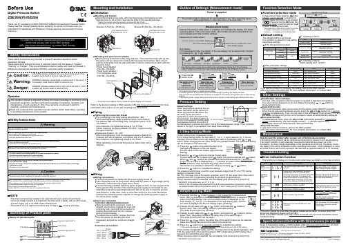
Other SettingsSummary of Product partsSimple Setting ModeTroubleshootingNote: Specifications are subject to change without prior notice and any obligation on the part of the manufacturer.© 2017 SMC Corporation All Rights ReservedAkihabara UDX 15F, 4-14-1, Sotokanda, Chiyoda-ku, Tokyo 101-0021, JAPANPhone: +81 3-5207-8249 Fax: +81 3-5298-5362URL Specifications/Outline with Dimensions (in mm)Refer to the product catalog or SMC website (URL ) for moreinformation about the product specifications and outline dimensions.PS※※-OMU0001 InstallationMounting with bracketMount the bracket to the body with mounting screws (Self tapping screws:Nominal size 3 x 8L (2 pcs)), then set the body to the specified position.∗: Tighten the bracket mounting screws to a torque of 0.5±0.05 Nm.Self tapping screws are used, and should not be re-used several times.∗: The panel mount adapter can be rotated through 90 degrees for mounting.•Bracket A (Part No.: ZS-46-A1)•Bracket B (Part No.: ZS-46-A2)Mounting with panel mount adapterMount part (a) to the front of the body and fix it. Then insert the body with (a) intothe panel until (a) comes into contact with the panel front surface. Next, mountpart (b) to the body from the rear and insert it until (b) comes into contact with thepanel for fixing.WiringWiring connectionsConnections should be made with the power supply turned off.Use a separate route for the product wiring and any power or high voltage wiring.Otherwise, malfunction may result due to noise.If a commercially available switching power supply is used, be sure to ground theframe ground (FG) terminal. If the switching power supply is connected for use,switching noise will be superimposed and it will not be able to meet the productspecifications. In that case, insert a noise filter such as a line noise filter/ferritebetween the switching power supplies or change the switching power supply tothe series power supply.How to use connectorConnector attachment/detachmentWhen connecting the connector, insert itstraight onto the pins, holding the lever andconnector body, and lock the connector bypushing the lever hook into the concavegroove on the housing.To detach the connector, remove the hookfrom the groove by pressing the leverdownward, and pull the connector straightout.DC(+)Pin No.OUT1OUT2FUNCDC(-)BrownBlackWhiteGrayBluePipingTightening the connection threadFor connecting to the body (piping specification: -M5)After hand tightening, apply a spanner of the correct size tothe spanner flats of the piping body, and tighten with a 1/6 to1/4 rotation.As a reference, the tightening torque is 1 to 1.5 Nm.(When replacing the piping adapter ZS-46-N∗, tighten it usingthe same method.)Piping specification: -01, -N01After hand tightening, hold the hexagonal spanner flats of thepressure port with a spanner, and tighten with 2 to 3 rotations.As a reference, the tightening torque is 3 to 5 Nm.When tightening, do not hold the pressure switch body with aspanner.Default settingsWhen the pressure exceeds the setvalue, the switch will be turned on.When the pressure falls below theset value by the amount ofhysteresis or more, the switch willbe turned off. The default setting isto turn on the pressure switch whenthe pressure reaches the centre ofthe atmospheric pressure and upper limit of the rated pressure range. If this condition,shown to the right, is acceptable, then keep these settings.Error indication functionThis function is to display error location and content when a problem or error has occurred.above are displayed, please contact SMC.Refer to the SMC website (URL ) for more information abouttroubleshooting.Power is supplied.button between1 and 3 sec.∗:The outputs will continue to operate during setting.∗:If a button operation is not performed for 3 seconds during the setting, the display will flash.(This is to prevent the setting from remaining incomplete if, for instance, an operator were to leave duringsetting.)∗:3 step setting mode, simple setting mode and function selection mode settings are reflected each other.[3 step setting mode (hysteresis mode)]orcan be changed in the same way.button once when the item to beThe set value on the sub display (right) will startflashing.orbutton.buttons are pressed and held simultaneously for 1 second orlonger, the set value is displayed as [- - -], and the set value will be the same as thecurrent pressure value automatically (snap shot function).Afterwards, it is possible to adjust the value by pressing button.button to complete the setting.The pressure switch turns on within a set pressure range (from P1L to P1H) duringwindow comparator mode.Set P1L, the lower limit of the switch operation, and P1H, the upper limit of the switchoperation and WH1 (hysteresis) following the instructions given above.(When reversed output is selected, the sub display (left) shows [n1L] and [n1H].)∗:Set OUT2 in the same way. (ex. P_2, H_2)∗:Setting of the normal/reverse output switching and hysteresis/window comparator mode switchingare performed with the function selection mode [F 1] OUT1 setting and [F 2] OUT2 setting.value[F 0] Units selection functionPeak/bottom value indicationbutton inmeasurement mode.Snap shot functionbuttons for 1 secondor longer simultaneously. Then, the set value of the sub display (right) shows [- - -], andthe values corresponding to the current pressure values are automatically displayed.Zero-clear functionbuttons are pressed for 1 second orlonger simultaneously, the main display shows [- - -], and the reset to zero.The display returns to measurement mode automatically.Key-lock functionTo set each of these functions, refer to the SMC website(URL ) for more detailed information, or contact SMC.button between 1 and 3 seconds in measurementmode. [SEt] is displayed on the main display. When the button is releasedwhile in the [SEt] display, the current pressure value is displayed on themain display, [P_1] or [n_1] is displayed on the sub display (left), and theset value is displayed on the sub display (right) (Flashing).or button to(The snap shot function can be used.)or button to set the(The snap shot function can be used.)or button, the delay time of the switch output can be selected.button for 2 seconds or longer to complete the setting.∗:If the button is pressed for less than 2 seconds, the setting will moves to the OUT2 setting.In the window comparator mode, set P1L, the lower limit of the switch operation, andP1H, the upper limit of the switch operation, WH1 (hysteresis) and dt1 (delay time)following the instructions given above.(When reversed output is selected, the sub display (left) shows [n1L] and [n1H].)∗:Set OUT2 in the same way.Function selection modebuttonbetween 3 and 5 seconds, to display [F 0].Select to display the function to be changed[F button for 2seconds or longer in function selection modeto return to measurement mode.∗:Some products do not have all the functions. If no functionis available or selected due to configuration of otherfunctions, [- - -] is displayed on the sub display (right).Names of individual partsRefer to the product catalog or SMC website (URL ) for moreinformation about panel cut-out and mounting hole dimensions.Pressure Setting3 Step Setting Mode(URL ) for more detailed information, or contact SMC.MaintenanceHow to reset the product after a power cut or forcible de-energizingThe setting of the product will be retained as it was before a power cut or de-energizing.The output condition is also basically recovered to that before a power cut or de-energizing, but may change depending on the operating environment. Therefore, checkthe safety of the whole installation before operating the product. If the installation is usingaccurate control, wait until the product has warmed up (approximately 10 to 15 minutes). Safety InstructionsBefore UseDigital Pressure SwitchZSE20A(F)/ISE20AThank you for purchasing an SMC ZSE20A(F)/ISE20A Series Digital Pressure Switch.Please read this manual carefully before operating the product and make sure youunderstand its capabilities and limitations. Please keep this manual handy for futurereference.Safety InstructionsThese safety instructions are intended to prevent hazardous situations and/orequipment damage.These instructions indicate the level of potential hazard with the labels of "Caution","Warning" or "Danger". They are all important notes for safety and must be followed inaddition to International standards (ISO/IEC) and other safety regulations.OperatorSwitch ONAt normal output Switch OFFSet valueP_1HysteresisH_1TimePressureDefault settingThe default setting is as follows.If no problem is caused by this setting,keep these settings.Connector pin numbers[F 2] Setting of OUT2Same setting as [F 1] OUT1.NOTE•The direct current power supply to be used should be UL approved as follows:Circuit (of Class 2) which is of maximum 30 Vrms (42.4 V peak), with UL1310 Class2 power supply unit or UL1585 Class 2 transformer.•The product is a UL approved product only if it has a mark on the body.。
FortiGate 200F 系列产品说明说明书
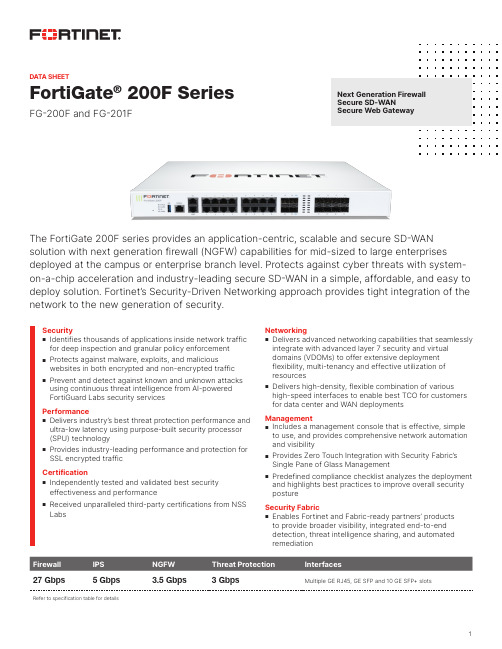
FortiGate ® 200F SeriesFG-200F and FG-201FThe FortiGate 200F series provides an application-centric, scalable and secure SD-WAN solution with next generation firewall (NGFW) capabilities for mid-sized to large enterprises deployed at the campus or enterprise branch level. Protects against cyber threats with system-on-a-chip acceleration and industry-leading secure SD-WAN in a simple, affordable, and easy to deploy solution. Fortinet’s Security-Driven Networking approach provides tight integration of the network to the new generation of security.NGFW Threat ProtectionInterfaces27 Gbps 5 Gbps 3.5 Gbps 3 GbpsMultiple GE RJ45, GE SFP and 10 GE SFP+ slotsRefer to specification table for detailsSecurity n Identifies thousands of applications inside network traffic for deep inspection and granular policy enforcementn Protects against malware, exploits, and maliciouswebsites in both encrypted and non-encrypted traffic n Prevent and detect against known and unknown attacksusing continuous threat intelligence from AI-powered FortiGuard Labs security servicesPerformancen Delivers industry’s best threat protection performance and ultra-low latency using purpose-built security processor (SPU) technologyn Provides industry-leading performance and protection forSSL encrypted trafficCertificationn Independently tested and validated best security effectiveness and performancen Received unparalleled third-party certifications from NSSLabsNetworkingn Delivers advanced networking capabilities that seamlessly integrate with advanced layer 7 security and virtual domains (VDOMs) to offer extensive deployment flexibility, multi-tenancy and effective utilization of resourcesn Delivers high-density, flexible combination of varioushigh-speed interfaces to enable best TCO for customersfor data center and WAN deploymentsManagement n Includes a management console that is effective, simple to use, and provides comprehensive network automation and visibilityn Provides Zero Touch Integration with Security Fabric’sSingle Pane of Glass Managementn Predefined compliance checklist analyzes the deploymentand highlights best practices to improve overall securitypostureSecurity Fabric n Enables Fortinet and Fabric-ready partners’ products to provide broader visibility, integrated end-to-end detection, threat intelligence sharing, and automated remediationNext Generation Firewall Secure SD-WANSecure Web GatewayDATA SHEETDATA SHEET | FortiGate® 200F SeriesDEPLOYMENTN ext Generation Firewall (NGFW)§Reduce the complexity and maximize your ROI by integrating threatprotection security capabilities into a single high-performance network security appliance, powered by Fortinet’s Security Processing Unit (SPU) §Full visibility into users, devices,applications across the entire attack surface and consistent security policy enforcement irrespective of asset location §Protect against network exploitable vulnerabilities with industry-validated IPS that offers low latency and optimized network performance §Automatically block threats ondecrypted traffic using the Industry’s highest SSL inspection performance, including the latest TLS 1.3standard with mandated ciphers §Proactively block newly discoveredENTERPRISE Secure Access SwitchFortiGate 200F Enterprise Branch Deployment(Secure SD-WAN)FortiGate 200F Campus Deployment(NGFW)Secure Web Gateway (SWG)§Secure web access from both internal and external risks, even for encrypted traffic at high performance §Enhanced user experience with dynamic web and video caching §Block and control web access based on user or user groups across URL’s and domains §Prevent data loss and discover user activity to known and unknown cloud applications §Block DNS requests against malicious domains §Multi-layered advanced protection against zero-day malware threats delivered over the webSecure SD-WAN§Consistent business application performance with accurate detection, dynamic WAN path steering on any best-performing WAN transport §Accelerated Multi-cloud access for faster SaaS adoption with cloud-on-ramp §Self-healing networks with WAN edge high availability, sub-second traffic switchover-based and real-time bandwidth compute-based traffic steering §Automated Overlay tunnels provides encryption and abstracts physical hybrid WAN making it simple to manage. §Simplified and intuitive workflow with SD-WAN Orchestrator for management and zero touch deployment §Enhanced analytics both real-time and historical provides visibility into network performance and identify anomalies §Strong security posture with next generation firewall and real- time threat protectionDATA SHEET | FortiGate® 200F SeriesHARDWAREFortiGate 200F/201F1. 2x GE RJ45 HA / MGMT Ports2. 16x GE RJ45 Ports3. 2x 10 GE SFP+ Slots4. 2x 10 GE SFP+ FortiLink Slots5.8x GE SFP SlotsInterfacesHardware FeaturesPowered by SPUn Fortinet’s custom SPU processorsdeliver the power you need to detect malicious content at multi-Gigabit speedsn Other security technologies cannot protect againsttoday’s wide range of content- and connection-based threats because they rely on general-purpose CPUs, causing a dangerous performance gap n SPU processors provide the performance neededto block emerging threats, meet rigorous third-party certifications, and ensure that your network security solution does not become a network bottleneckTrusted Platform Module (TPM)The FortiGate 200F Series features a dedicated module that hardens physical networking appliances by generating, storing, and authenticating cryptographic keys. Hardware-based security mechanisms protect against malicious software and phishing attacks.CONSOLEUSBHAMGMT12345678910111213X1X3X2X41415161718192021222324FortiGate 200FPOWERHA ALARM STATUS 43215AC LINE 100-240V AC 50-60Hz 2-1.2A AC LINE 100-240V AC 50-60Hz 2-1.2A1U CP 9/480GBAC DUALNP6XLiteTPMNetwork ProcessorFortinet’s new, breakthrough SPU NP6XLite network processor works inline with FortiOS functions delivering: §Superior firewall performance for IPv4/IPv6, SCTP and multicast traffic with ultra-low latency §VPN, CAPWAP and IP tunnel acceleration§Anomaly-based intrusion prevention, checksum offload, and packet defragmentation §Traffic shaping and priority queuingContent ProcessorFortinet’s ninth generation custom SPU CP9 contentprocessor works outside of the direct flow of traffic and accelerates the inspection.Access Layer SecurityFortiLink protocol enables you to converge security andthe network access by integrating the FortiSwitch into the FortiGate as a logical extension of the NGFW. These FortiLink enabled ports can be reconfigured as regular ports as needed.DATA SHEET | FortiGate® 200F Series FORTINET SECURITY FABRICFortiOS™Operating SystemFortiOS, Fortinet’s leading operating system enable the convergence of high performing networking and security across the Fortinet Security Fabric delivering consistent and context-aware security posture across network endpoint, and clouds. The organically built best of breed capabilities and unified approach allows organizations to run their businesses without compromising performance or protection, supports seamless scalability, and simplifies innovation consumption.The release of FortiOS 7 dramatically expands the Fortinet Security Fabric’s ability to deliver consistent security across hybrid deployment models of Hardware, Software, and Software As-a-Service with SASE and ZTNA, among others.Security FabricThe industry’s highest-performing cybersecurity platform,powered by FortiOS, with a rich ecosystem designed to span the extended digital attack surface, delivering fully automated, self-healing network security.§Broad: Coordinated detection and enforcement across the entire digital attack surface and lifecycle with converged networking and security across edges, clouds, endpoints, and users§Integrated: Integrated and unified security, operation, and performance across different technologies, location, deployment options, and the richest ecosystem§Automated: Context aware, self-healing network and security posture leveraging cloud-scale and advanced AI to automatically deliver near-real-time, user-to-application coordinated protection across the FabricThe Fabric empowers organizations of any size to secure and simplify their hybrid infrastructure on the journey to digital innovation.SERVICESFortiGuard™Security ServicesFortiGuard Labs offer real-time intelligence on the threat landscape, delivering comprehensive security updates across the full range of Fortinet’s solutions. Comprised of security threat researchers, engineers, and forensic specialists, the team collaborates with the world’s leading threat monitoring organizations and other network and security vendors, as well as law enforcement agencies.FortiCare™ServicesFortinet is dedicated to helping our customers succeed, and every year FortiCare services help thousands of organizations get the most from their Fortinet Security Fabric solution. We have more than 1,000 experts to help accelerate technology implementation, provide reliable assistance through advanced support, and offer proactive care to maximize security and performance of Fortinet deployments.DATA SHEET | FortiGate® 200F Series SPECIFICATIONSFORTIGATE 200F FORTIGATE 201F Interfaces and ModulesGE RJ45 Ports16GE RJ45 Management / HA 1 / 1GE SFP Slots810 GE SFP+ FortiLink Slots (default)210 GE SFP+ Slots2USB Port1Console Port1Onboard Storage01x 480 GB SSD Included Transceivers0System Performance — Enterprise Traffic MixIPS Throughput 2 5 GbpsNGFW Throughput 2, 4 3.5 GbpsThreat Protection Throughput 2, 5 3 GbpsSystem Performance and CapacityIPv4 Firewall Throughput(1518 / 512 / 64 byte, UDP)27 / 27 / 11 GbpsFirewall Latency (64 byte, UDP) 4.78 μsFirewall Throughput (Packet per Second)16.5 Mpps Concurrent Sessions (TCP) 3 MillionNew Sessions/Second (TCP)280,000Firewall Policies10,000IPsec VPN Throughput (512 byte) 113 GbpsGateway-to-Gateway IPsec VPN Tunnels 2,000Client-to-Gateway IPsec VPN Tunnels16,000SSL-VPN Throughput 2 GbpsConcurrent SSL-VPN Users(Recommended Maximum, Tunnel Mode)500SSL Inspection Throughput (IPS, avg.HTTPS) 34 GbpsSSL Inspection CPS (IPS, avg. HTTPS) 33,500SSL Inspection Concurrent Session(IPS, avg. HTTPS) 3300,000Application Control Throughput(HTTP 64K) 213 GbpsCAPWAP Throughput (HTTP 64K)20 GbpsVirtual Domains (Default / Maximum)10 / 10Maximum Number of FortiSwitchesSupported64Maximum Number of FortiAPs (Total /Tunnel)256 / 128Maximum Number of FortiTokens5,000High Availability Configurations Active, Active-Active, Passive, ClusteringFORTIGATE 200F FORTIGATE 201F Dimensions and PowerHeight x Width x Length (inches) 1.73 x 17.01 x 13.47Height x Width x Length (mm)44 x 432 x 342Weight9.92 lbs (4.5 kg)10.14 lbs (4.6 kg) Form Factor(supports EIA/non-EIA standards)Ear Mount, 1 RUAC Power Supply100–240V AC, 50/60 HzPower Consumption(Average / Maximum)101.92 W / 118.90 W104.52 W / 121.94 W Current (Maximum)100V / 2A, 240V / 1.2AHeat Dissipation405.70 BTU/h436.98 BTU/h Redundant Power Supplies YesOperating Environment and CertificationsOperating Temperature32–104°F (0–40°C)Storage Temperature-31–158°F (-35–70°C) Humidity20–90% non-condensingNoise Level49.9 dBAForced Airflow Side to BackOperating Altitude Up to 7,400 ft (2,250 m) Compliance FCC Part 15B, Class A, CE, RCM, VCCI, UL/cUL, CB, BSMI Certifications ICSA Labs: Firewall, IPsec, IPS, Antivirus,SSL-VPN, IPv6Note: All performance values are “up to” and vary depending on system configuration.1. IPsec VPN performance test uses AES256-SHA256.2. IPS (Enterprise Mix), Application Control, NGFW and Threat Protection are measured withLogging enabled.3. SSL Inspection performance values use an average of HTTPS sessions of different ciphersuites.4. NGFW performance is measured with Firewall, IPS and Application Control enabled.5. Threat Protection performance is measured with Firewall, IPS, Application Control, URLfiltering, and Malware Protection with sandboxing enabled.DATA SHEET | FortiGate® 200F SeriesCopyright © 2021 Fortinet, Inc. All rights reserved. Fortinet , FortiGate , FortiCare and FortiGuard , and certain other marks are registered trademarks of Fortinet, Inc., and other Fortinet names herein may also be registered and/or common law trademarks of Fortinet. All other productor company names may be trademarks of their respective owners. Performance and other metrics contained herein were attained in internal lab tests under ideal conditions, and actual performance and other results may vary. Network variables, different network environments and other conditions may affect performance results. Nothing herein represents any binding commitment by Fortinet, and Fortinet disclaims all warranties, whether express or implied, except to the extent Fortinet enters a binding written contract, signed by Fortinet’s General Counsel, with a purchaser that expressly warrants that the identified product will perform according to certain expressly-identified performance metrics and, in such event, only the specific performance metrics expressly identified in such binding written contract shall be binding on Fortinet. For absolute clarity, any such warranty will be limited to performance in the same ideal conditions as in Fortinet’s internal lab tests. Fortinet disclaims in full any covenants, representations, and guarantees pursuant hereto, whether express or implied. Fortinet reserves the right to change, modify, transfer, or otherwise revise this publication without notice, and the most current version of the publication shall be applicable. Fortinet disclaims in full any covenants, representations, and guarantees pursuant hereto, whether express or implied. Fortinet reserves the right to change, modify, transfer, or otherwise revise this publication without notice, and the most current version of the publication shall be applicable.1 GE SFP RJ45 transceiver module FN-TRAN-GC 1 GE SFP RJ45 transceiver module for all systems with SFP and SFP/SFP+slots.1 GE SFP SX transceiver module FN-TRAN-SX 1 GE SFP SX transceiver module for all systems with SFP and SFP/SFP+ slots.1 GE SFP LX transceiver module FN-TRAN-LX 1 GE SFP LX transceiver module for all systems with SFP and SFP/SFP+ slots.10 GE SFP+ RJ45 transceiver module FN-TRAN-SFP+GC 10 GE SFP+ RJ45 transceiver module for systems with SFP+ slots.10 GE SFP+ transceiver module, short range FN-TRAN-SFP+SR 10 GE SFP+ transceiver module, short range for all systems with SFP+ and SFP/SFP+ slots.10 GE SFP+ transceiver module, long range FN-TRAN-SFP+LR 10 GE SFP+ transceiver module, long range for all systems with SFP+ and SFP/SFP+ slots.10 GE SFP+ transceivers, extended rangeFN-TRAN-SFP+ER10 GE SFP+ transceiver module, extended range for all systems with SFP+ and SFP/SFP+ slots.ORDERING INFORMATIONBUNDLESFortiGuard BundleFortiGuard Labs delivers a number of security intelligence services to augment the FortiGate firewall platform. You can easily optimize the protection capabilities of your FortiGate with one of these FortiGuard Bundles.Bundles 360 Protection Enterprise Protection Unified Threat ProtectionAdvanced ThreatProtectionFortiCareASE 124x724x724x7FortiGuard App Control Service ••••FortiGuard IPS Service••••FortiGuard Advanced Malware Protection (AMP) — Antivirus, Mobile Malware, Botnet, CDR, Virus Outbreak Protection and FortiSandbox Cloud Service••••FortiGuard Web and Video 2 Filtering Service •••FortiGuard Antispam Service •••FortiGuard Security Rating Service ••FortiGuard IoT Detection Service ••FortiGuard Industrial Service ••FortiConverter Service••SD-WAN Orchestrator Entitlement •SD-WAN Cloud Assisted Monitoring •SD-WAN Overlay Controller VPN Service • Fortinet SOCaaS •FortiAnalyzer Cloud •FortiManager Cloud•1. 24x7 plus Advanced Services Ticket Handling2. Available when running FortiOS 7.0。
最新产品说明书5篇

产品说明书5篇产品说明书5篇产品说明书(1)(一)产品说明书的基本含义产品说明书是对产品的结构、性能、规格、用途、使用方法、维修保养等的说明性文字。
(二)产品说明书的写作要点通常来说,产品说明书主要包括以下主要内容:1 产品概况;2 产品的性能和特点;3 产品的使用方法;4 产品的保养与维修;5 其他事项。
(三)格式范例公司产品说明书中医理论认为:“人体是一个平衡的有机整体,病弱的根本原因在于平衡失调。
”然而,人体的平衡,却时常受到内外各种因素的破坏:工作生活的压力、季节气候的变化、生理机构的老化……很多的原因让人穷于应付。
生物保健口服液,遵循自然法则,以特殊工艺从生物中提取有效的活性物质,增强人的体质,从而迅速恢复被破坏的机能;并通过帮助人体平衡地吸收膳食中的营养及各类元素,以保证人体器官功能的物质所需,从而达到预防、防治疾病的保健目的。
一、功能双向调节机体功能,延长细胞寿命,提高机体免疫力,提高工作、运动能力,振奋精神,充沛体力,促进疲劳恢复和病后康复。
二、适用范围1 食欲不振、消化不良、睡眠不安、精神衰弱、疲倦无力、精力不足。
2 贫血、十二脂溃疡、胃炎、高血压的辅助治疗。
3 病后体弱。
4 老年慢性病,人体机能衰退。
5 儿童、青少年营养不良、发育不全、学习注意力不集中、记忆力差、学习、考试用脑过度。
三、用法每日 2次,每次 1片,小儿减半,早午服用。
以 20! 30天为 1个疗程。
然后停服1周,若再进行 1个疗程,效果更佳。
本品为纯生物制剂,不含防腐剂和化学合成药物,经药理实验和临床试验均无副作用,可长期服用。
四、贮存干燥阴凉处,或冰箱内保存。
批准文号:产品说明书(2)Spiral chute1、product descriptionSpiral chute is integrated spiral separator, spiral chute, shaker, centrifugal concentration machine characteristics of the equipment, mining, mineral processing is the best equipment, especially the seaside, riverside, sand beach, the stream of placer mining is more ideal. The product has the advantages of reasonable structure, simple installation, covers an area of small, simple operation, stable ore beneficiation, clear, large processing capacity, high efficiency enrichment ratio high, highrecovery rate, reliable operation characteristics. Have weight light, moisture-proof, rust-proof, corrosion resistance, of the feeding quantity and concentration, particle size, quality of volatility adaptability is strong, no noise.2、Separation principleSpiral chute is a membrane flow gravity separation equipment, the selection principle is the use of useful minerals and gangue in proportion, particle size, shape differences, in rotating inclined flow by gravity, centrifugal force, hydrodynamic pressure and friction force with different groove face, realize the useful minerals and gangue stratification, branch tape sorting. Heavy, coarse granularity, fast sedimentation of particles gradually moved towards the spiral groove inner edge, the proportion of small, fine particle size, particle sedimentation slow gradually moved to the spiral groove edge, gradually banding, culminating in the spiral groove end by cutting ore tank is respectively connected out, to realize separation.3、ApplicationThe sorting equipment for grain size mm fine iron ore, titanium ore, chromite, pyrite, zircon, monazite, rutile , phosphorus ore, tungsten, tin, B mine of tantalum niobium ore with the difference of specific gravity, and other non-ferrous metals, rare metals and non-metallic mineral. The sorting process with a stable, easy to control, to allow changes to the mineral concentration range, high enrichment, high recovery rate, small occupation area, little water consumption, simple structure, no need of power, large processing quantity, simple installation, convenient operation, small investment, quick advantages.4、The method of useThe spiral chute is erected, calibrated vertical line, with metal or wood fixed in position, by the sand pump will ore to spiral top two inlet,adding supplemental water, mineral ore concentration regulation paddle, paddle down naturally from high swirl, in rotating inclined flow produces a kind of inertial centrifugal force, with ore proportion, particle size, shape differences, swirl through the action of gravity and centrifugal force, will be mine and sand separating, concentrate into the concentrate pipe connected with a hopper, tailings into tailing bucket a pipeline is connected to a sand pool, then the pump discharge, finished processing the whole process.5、Structure and technical parameterMainly by the ore separator, cross, to mine groove, helical groove, cutting trough, pick ore bucket and slot pillar of seven components. The helical groove is spiral chute of the main components, each spiral chute is 2 -- 4 head spiral groove, each head spiral groove is composed of 5 spiral plates (according to mineral properties and beneficiation process need, after tests also consider 4 circles, in order to reduce the equipment height) spiral plate by bolts are fixed together, spiral sheet is made of glass fiber reinforced plastic (FRP) made, light weight, anti-corrosion, moisture-proof, anti deformation and strength.6、InstallationSpiral chute installation procedures and requirements:1) First check the glass steel spiral slice quality (especially the work surface quality), size and shape to meet the requirements for assembly2) Screw plate connecting bolt hole by the general factory in advance with a drill. If the manufacturer has no processing is required, according to the same template drilling, in order to ensure good interchangeability.3) Bolt the five coil sheet are connected into a group of spiral groove, level set, two adjacent flange connection within the surface smooth transition is connected, special attention should be paid on the surface may not be lower than the corresponding lower sheet surface. Along thediameter direction.(the slot width direction) to edge alignment as the standard, do not allow plate rim inside, so the installation is intended to prevent the occurrence of ore fluid splash. Joint gap, with putty.4) The coupled five of a group of four (or two or three) spiral groove rotating together into a desired shape, distribution.5) The four roots (three) column is respectively arranged in four (or three, two) spiral groove, bolt the spiral groove and the pillar is fixed, then install the cross (tripod), so that each spiral along the park are cloth, then all bolts. After installation, spiral plate to maintain the natural shape, with no obvious variant.6) Would give mine groove and product interception groove are respectively arranged in the spiral groove of the head end and the tail end to ensure that the connection of close water leakage. If there is a gap, by coating sealing. To ensure the smooth transition of groove surface.7) To mine even divider and product assemble bucket and the slot bracket is not connected, free placed on the bracket, the installation should pay attention to in the chart are position. Each row of tube to distributor are respectively aligned with corresponding to the ore tank.6-S shaking table1、ApplicationThe 6-S shaking table is one of the main equipment of gravity concentration, it is widely used in separating tungsten, tin, tantalum, niobium, gold and other rare metals and precious metal ore. Can be used for roughing, concentration, scavenging different operations, separating coarse sand fine sand, clay (- of different grain grade It can also be used to separate iron, manganese ore and coal. When processing tungsten, tin ore, the table effective recycling particle size range for the mm.2、PerformanceThe shaking table is in the beneficiation process is complex a tiltbed plane, ore particle swarm from the bed surface angle to the trough into, at the same time by lateral flushing water supply to the water tank, and the mineral particles in gravity, lateral flow momentum, bed reciprocating asymmetric motion produced by the inertia and friction effects next, according to the proportion and hierarchical granularity, and along the bed surface for longitudinal movement along the inclined bed surface and transverse motion. Therefore, specific gravity and particle size of different mineral particles along the direction of movement of the respective gradually by the A side to side B fan-shaped shed, concentrate and tailings from the end side of the discharging end is divided into different, concentrate, middling and tailings.6-s has a double high rich ore ratio, high separation efficiency, safeguards easily, convenient for adjusting the stroke. In change cross fall and stroke is still maintain the surface of bed movement balance, the spring is placed in the box body, compact structure, and can in turn draw final concentrate and tailings.3、Classification1)According to the different position of ore, shaker can be divided into right and left type cradle type cradle two forms. The right type cradle for the ore location for the rocking mechanism is on the right side, left type cradle to mine is located in the left.2)6-S shaker can be divided into fixed shaking table,channel bar shaking table, big channel steel shaking table.3)According to the concentration particle size, divided into coarse sand table, sand table and slimmer three.4、StructureThis table is mainly composed of a bed head, motor, adjustable slope, the bed surface, mine shafts, sink, and reflex and lubrication system of eight components.The surface of bed longitudinal reciprocating motion through a crank connecting rod type driving mechanism to realize. The electric motor through the belt drive to make the big belt wheel drives the crankshaft to rotate, the rocker made subsequently moves up and down, rocker downwards, elbow board drive rear axle and the reciprocating rod moves backwards, the spring being compressed. The bed surface is through linkage seat and a reciprocating lever connected, so this is also so the bed surface for backward movement, when the rocker upward movement, due to the tension spring drive, the bed surface will move forward.5、Specification6、Installation and cautions1) On the basis of drawing, reserved anchor screw holes or pouring good foundation plate, drilling, hole expansion, the construction of concrete foundation.2) The shaker frame placed on the basis, make each place, calibration and pad frame beam level.3) The Department of anchor screws tightening, the cradle is fixed on the basis of.4) Mounted on the drag device, bed surface, bedside and bed and the bed surface connecting rod, attention should be to the front to bedside flywheel.5) Connect the switch of the motor insurance, check whether the motor leakage, and then good motor wire.6) The bed surface is not strong beat, collision; not in high temperature and heavy pressure; avoid oil pollution and sun and rain, prevent degeneration.7) After the installation, a detailed examination, the confirmation, removal of equipment and surrounding sundries.8) Roller with 10-20 G oil, not to splash as well. The seat slidingrack injection oil to drown the sliding bearing and the lower bearing contact fit; lever type rocking frame bearing has been manufactured with good lithium grease.9)Put the washing water air machine test machine operation, observation and examination: starting and operation, the moving parts are not loose fever or unusual sounds.10)Empty test machine to normal, can load test machine, according to the selected minerals, inspection and adjustment of the stroke, stroke, springs, bed longitudinal slope and transverse slope so as to achieve the optimal separation effect. After normal cleaning, it can be put into production.7、operation and maintenance1)Feeding volume and concentration of proper, if give mine too large volume, concentration, recovery rate.2)The bed surface transverse slope large, flushing water should be smaller; slope is small, flushing water shall be selected.3) Stroke and frequency of stroke should be adjusted properly. Stroke is too small too big, affected grain stratification. To change the diameter of a motor belt pulley, adjustable stroke Adjusting spindle and the set of eccentric combination, can have different stroke,Permanent magnetic separator1、Range of applicationThe series of magnetic separator for sorting magnetic minerals, non-metallic materials and waste materials deironing. Such as: reduction of titanium magnetite, iron ore smelting in front of the purifying selection, ceramic clay, feldspar, quartz, iron ore, coal and other materials in addition to iron.2、The structure and working principleCT series cylinder type permanent magnetic separator, drum body anda groove near the magnetic system parts are made of non-magnetic material of stainless steel, cylinder end cap cast in aluminum, and other ordinary steel production. Equipment structure is composed of a machine frame, body, a cylinder, a magnetic system, power plant, feed, water, discharging part. The groove body and cylinder distance according to the mineral separation of lifting adjustment, magnetic angle can be adjusted at.(no water supply device of dry type)1)CTC dry magnetic separator: dry aggregate from the hopper into the cylinder directly to the upper or lower portion of the drum, magnetic mineral particles are magnetic in the surface of the drum, winding drum rotates to the edges of the natural unload magnetic system. Non magnetic mineral particles by the action of gravity and centrifugal force and magnetic products into different ore bucket. Magnetic products magnetic products and is arranged in the middle of ore isolation plate, according to the mineral material selected to adjust the situation.2)CTB semi-counter current magnetic separator magnetic lines in the lower part of drum. Pulp from the tank into the lower part of the lower roller, non-magnetic minerals in the direction of movement and the rotation of the drum in the opposite direction, magnetic minerals moving direction and rollers rotate in the same direction. The lower part of the spray pipe body is inserted, is used to adjust the separating operation of slurry concentration, the slurry dispersed into loosely suspended state into the separation space. The magnetic particles in the magnetic system of magnetic field force, is absorbed on the surface of the roller, roller together with the upwardly mobile. In the moving process, because the magnetic lines of alternating polarity, so that the magnetic mineral particles into a chain of turning, in the turning process, the inclusions in the magnetic mineral particles in non magnetic mineral impurities is cleared, so as to effectively improve the purpose of magnetic products. Semi countercurrentmagnetic separator for mineral slurry concentration and granularity is sensitive to change, when the concentration is too large or grain through the metropolitan influence index of mineral processing.3)CTS downstream separator: feeding direction and the direction of rotation of the drum or magnetic mineral moving direction. The pulp comprises feeding bucket directly into the cylinder below the magnetic system, non magnetic particle and magnetic weak mineral particles from beneath the tank bottom roller two and the gap between the discharge, magnetic mineral particles are sucked on the surface of the cylinder, with the roller to rotate together to the magnetic system edge discharge, magnetic ore discharging position is provided with a discharging water pipe. Downstream separator on mineral beneficiation of wide adaptability, easy separating space is smooth without obstruction, particularly applicable to contain magnetic minerals a larger proportion of the magnetic separation process.4)CTN upstream separator: feeding direction and drum rotation direction or magnetic material moves in the opposite direction. The pulp comprises feeding bucket directly into the cylinder below the magnetic system, non magnetic particle and magnetic weak mineral particles from tank bottom hole discharging tailings, magnetic mineral particles with the roller against the feed direction to give mine is discharged to the magnetic ore groove, for the reduction of magnetic products with non-magnetic mineral, in magnetic ore unloading mounted before the cleaning water pipe, magnetic ore discharging position is provided with a discharging flushing pipe. Countercurrent separation machine due to the magnetic ore discharge end distance to mine mouth close, magnetic turning effect is poor, so the magnetic ore grade to be slightly lower, but its tailings ore export far away from the mouth, the pulp after longer divided districts, increases the magnetic mineral particles are magnetically attracted to opportunity,all the magnetic separator magnetic product recovery rate is quite high, counter flow type magnetic separator suitable for only require nonmagnetic product precision of various minerals.3、Specification4、Installation and use1) At first machine installed must check the transport loading and unloading is loose, damaged.2) The horizontal position, implement, conventionally grounded.3) Check, adjust the magnetic system to the fixed position processing and working distance.4) Before the first test machine, drum empty running again, water supply, feeding, everything is normal, and then evenly feeding load test machine. According to the material separation requirements for adjusting the output, quality, recovery rate.5、Preventive maintenance1) Removing: drum removable from the frame, standing on a stable level of supporting frame. Have a head driving device placed below.2) When hoisting drum magnetic parts do not close to the strong magnetic tool or magnetic materials.3) Will fixed aluminum cover fastening screw removal. The 4 screw mount aluminum end cover removing hole. Parallel to the rotating 4 pearl will cover up after unloading, and then remove the lower end cover fastening screw, can come up with a stainless steel cylinder. Aluminum cover middle small iron cover for the bearing cover and cover solid screw.4) The assembly must be completely to the magnetic surface and stainless steel inner cylinder of clean.5) Transmission gears, bearings, reducer shall be regularly maintained and filling calcium base grease lubricating oil.6、Cautions1) Strong magnetic tools, articles shall not be close to the magnetic system.2) Do not beat, collision stainless steel tube.3) Super size mineral, not into the machine, so as not to get stuck or wear of stainless steel copper cylinder.4) Abnormal sound, should be excluded.Ball mill1、Purpose and use scopeBall mill is the material being broken, and then smash the key equipment. Mill widely used in cement, silicate products, new building materials, refractory materials, fertilizer, black and non-ferrous metal processing and glass ceramic production industry, for all kinds of ores and other materials may be grinding of dry or wet grinding.2、Working principleThis machine is a horizontal cylinder rotating device, outer gear transmission, the warehouse has stepped lining board or corrugated liner, built in different specifications of steel balls, the rotation of the cylinder to generate centrifugal force will bring the steel ball to a certain height after the fall, the material produces severe impact and abrasive. Powder through the discharge grate discharge, then finish grinding operation.3、StructureThe equipment consists of feeding, discharging part, turning part, a transmission part (reducer, small transmission gear, motors, electrical control) and other major parts. Hollow shaft with steel castings, the liner is detachable, rotary gear hobbing with casting, cylinder liner wear studded body, has good abrasion resistance. The machine running stable, reliable work.4、Specification5、Installation and adjustment1)The basic requirements of installation:A、Bill mill should be installed on a solid concrete foundation;B、Ball mill cylinder should be installed after the ground with sufficient height, so as to facilitate the replacement of cylinder liner and grinding body, and a screw bolt lining board;C、Our generation base map, there are parts of a machine center line and the center line and the installation of anchor bolt anchor bolt size, random supply, base map size only remaining user base design reference, not for construction of.2)General requirements for the installationA、Machine parts are in the transport loading and unloading damage, such as damage should be trimmed.B、Machine parts are in the transport loading and unloading damage, such as damage should be trimmed.C、All the connecting bolts should be uniform, firmly tightened。
迪文科技DWIN Technology DMG48320C035_03WTC产品说明书
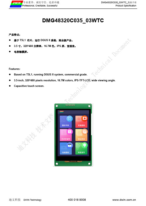
DMG48320C035_03WTC_数据手册Professional,Creditable,Successful Product SpecificationDMG48320C035_03WTC产品特点:●基于T5L1芯片,运行DGUS II系统,商业级产品。
● 3.5寸,320*480分辨率,16.7M色,IPS屏,宽视角。
●电容触摸屏。
Features:●Based on T5L1,running DGUS II system,commercial grade.● 3.5-inch,320*480pixels resolution,16.7M colors,IPS-TFT-LCD,wide viewing angle.●Capacitive touch screen.DMG48320C035_03WTC_数据手册Professional,Creditable,Successful Product Specification1、硬件及接口Hardware and interface1.1硬件接口图Hardware interface硬件接口图Hardware interface1.2接口说明Interface description序号No.名称Name说明Description1T5L1芯片T5L1ASIC迪文自主研发,2019年量产,1MBytes片内Nor Flash,其中512KBytes用于存储用户数据库,擦写次数>100,000次Developed by DWIN.Mass production in2019,1MBytes Nor Flash on thechip,512KBytes used to store the user database.Rewrite cycle:over100,000times2液晶屏接口LCM interfaceFPC40_0.5mm,RGB接口FPC40_0.5mm,RGB interface3电容触摸屏接口CTP interfaceIIC接口IIC interface4用户接口User interface用于供电和串口通讯,10Pin_1.0mm带锁扣座子。
产品说明书

(二)正文
正文是商品说明书的核心部分,各种商品不同,需要说 明的内容也不同,有的说明商品的用法,有的说明商品 的功能,有的说明其构造,有的说明其成分等,千差万 别,各有侧重。例如 食品 说明书重在说明其成份,使用 方法及保质期限;药物说明书重在说明其构成成份,基 本效用及用量;电器说明书重在说明其使用和保养方法 等。一般情况包括以下几个方面的内容:
因此,我们一定要为我们的产品出具说明书,并且在撰写 说明书时一定要准确,不可夸大应该实事求是!!
在美国读说明书
去年到美国探望妹妹。妹妹刚生了一个宝贝,我打算买一张可折叠的婴 儿床送给她。销售员现场为我演示了如何折叠婴儿床,等我付完款,销售 员又指着婴儿床说明书提醒我说: “请注意这一条——您在折叠床的时候, 一定要留意床上是否有您的孩子,如果孩子在床上,请一定将他抱走再折 叠。” 后来去买电熨斗也遇到类似的事情。那次我买了一个电熨斗,转身离去 时,销售员居然追了上来提醒我说:“你熨烫衣服前,必须把要熨烫的衣 服脱下来,千万不要熨烫穿在身上的衣服。”说着她拿出包装盒里说明书 指着“注意事项”反复问我:“UNDERSTAND(明白)?”我一看“注意 事项”不禁哑然失笑,除了上面那一条外,还注明“千万不要把电熨斗当 取暖器、千万不要用电熨斗煎鸡蛋、千万不要用电熨斗行使家庭暴力……” 为什么美国商品的说明书、美国的商场促销员总把消费者当“弱智” 看待?写上这些不太可能发生的事情有必要吗?美国的商家最害怕的就是 打官司,万一消费者使用商家的产品发生了什么意外,肯定会有一场旷日 持久的官司等着商家。商家费时费力不说,万一官司输了还面临重大的经 济损失。与其这样还不如防范于未然,把许多设想的意外先在说明书上写 清楚。这就是美国商品说明书的“注意事项”体贴入微的原因了。
Polymer 锂离子电池产品规格说明书

Specification Approval Sheet Name:Polymer Lithium-Ion BatteryModel: CELLEVIA BATTERIES LP573450SPEC:3.7V/ 980mAhNumber: 573450Specification Modification RecordsContent1.Scope:This specification describes the Product Specification of chargeable Polymer Lithium-IonBattery produced by Cellevia.Any copies are invalid without our company’s approval2.Model :3.Cell parameters Index:3.2 Parameters of batterythe temperature.4.Electronic Characteristics test and inspection:4.1 Standard testing environmentUnless special stated, tests should be done within one month of delivery and thecharging-recharging times is less than 5 times. The following is test conditions: Ambient Temperature: 25℃±0.5℃Ambient Humidity: 65 ±20%4.2 The requirement of measure instrument(1) The measure instrument is passed tested by qualified institute.(2) The accuracy of the size instrument is not more than 0.01mm.(3) The accuracy of multimeter is not less than 0.5%. while measure the voltage, theinternal resistance mustn’t less than 10KΩ.(4) The principal of the internal resistance is 1KHz LCR, the accuracy is 0.2%.(5) The internal resistance is changeable, it varies according to the temperature and thecharging mode. And it is relevant to the PTC and the length and the Capacity of the drawing line.(6) The current accuracy of the battery test system is more than ±0.1%,isobaricallyaccuracy is ±0.5%, timer accuracy is less than ±0.1%.(7) The accuracy of the temperature meter is less than ±0.5℃.4.3 Visual inspectionAny visual inspection defects will affect the electronic characteristics, such as cracks,leakage, and flaw, are not inexistence.Notes: The Max. voltage while charging is not more than 4.25V.The Max.protective voltage designed on PCB board should not more than4.3V.5. Storage and others5.1 Long Period StorageIf the cell has been stored for 3 month, it should be transfer to a dry and cool environment. Storage Voltage is between 3.6V and 3.9V and the storage conditions as Item 4.1.5.2Any matters that this specification does not cover should be conferred between theSpecification Approval sheet6.Drawing6.1 Assembly diagram(not in scale)Model:L573450! Danger●Strictly prohibits heat or throw cell into fire.●Strictly prohibits throw and wet cell in liquid such as water, gasoline or drink etc.●Strictly prohibits use leave cell close to fire or inside of a car where temperature may be above60°C. Also do not charge / discharge in such conditions.●Strictly prohibits put batteries in your pockets or a bag together with metal objects such asnecklaces. Hairpins,coins, or screws. Do not store or transportation batteries with such objects.●Strictly prohibits short circuit the (+) and (-) terminals with other metals.●Do not place Cell in a device with the (+) and (-) in the wrong way around.●Strictly prohibits pierce Cell with a sharp object such as a needle.●Strictly prohibits disassemble or modify the cell.●Strictly prohibits welding a cell directly.●Do not use a Cell with serious scar or deformation.●Thoroughly read the user’s manual before use, inaccurate handling of lithium ion rechargeablecell may cause leakage, heat, smoke, an explosion, or fire, capacity decreasing.! Warning●Strictly prohibits put cell into a microwave oven, dryer, or high-pressure container.●Strictly prohibits use cell with dry cells and other primary batteries, or new and old battery orbatteries of a different package, type, or brand.●Stop charging the Cell if charging is not completed within the specified time.●Stop using the Cell if abnormal heat, odor, discoloration, deformation or abnormal condition isdetected during use, charge, or storage.●Keep away from fire immediately when leakage or foul odor is detected.●If liquid leaks onto your skin or clothes, wash well with fresh water immediately.●If liquid leaking from the Cell gets into your eyes, do not rub your eyes. Wash them well with cleanedible oil and go to see a doctor immediately.! Caution●Before using the Cell, be sure to read the user’s manual and cautions on handling thoroughly.●Charging with specific charger according to product specification. Charge with CC/CV method.Strictly prohibits revered charging. Connect cell reverse will not charge the cel. At the sametime, it will reduce the charge-discharge characteristics and safety characteristics, this will leadto product heat and leakage.●Store batteries out of reach of children so that they are not accidentally swallowed.●If younger children use the Cell, their guardians should explain the proper handling.●Before using the Cell, be sure to read the user’s manual and cautions on handling thoroughly.●Batteries have life cycles. If the time that the Cell powers equipment becomes much shorter thanusual, the Cell life is at an end. Replace the Cell with a new same one.●When not using Cell for an extended period, remove it from the equipment and store in aplace with low humidity and low temperature.●While the Cell pack is charged, used and stored, keep it away from objects or materials with staticelectric charges.●If the terminals of the Cell become dirty, wipe with a dry clothe before using the Cell.●Storage the cells in storage temperature range as the specifications, After full discharged, wesuggest that charging to 3.9~4.0V with no using for a long time.●Do not exceed these ranges of the following temperature ranges.Charge temperature range : 0 °C to 45 °C;Discharge temperature range : -20 °C to 60 °C.(When using equipment)Handling Precaution and GuidelineFor LIP (Lithium-Ion Polymer) Rechargeable BatteriesPrefaceThis document of ‘Handling Precautions and Guideline LIP Rechargeable Batteries’shall be applied to the battery cells manufactured by CELLEVIA.Note (1): The customer is requested to contact CELLEVIA in advance, if and when the customer needs other applications of operating conditions than those described in this document. Additional experimentation may be required to verify performance and safety under such condition.Note (2): CELLEVIA will take no responsibility for any accident when the cell is used under other condition.Note (3): CELLEVIA will inform, in a written form, the customer of improvement(s) regarding proper use and handling of the cell, if it is deemed necessary.1. Charging 1.1ChargingCurrent:Charging current should be less than maximum charge current specified in theSpecification Approval Sheet.1.2 Charging Voltage:Charging voltage should be less than the maximum nominal voltage 4.2V, andthe charging voltage upper limited is 4.30V(single pack).1.3 Charging Temperature:The cell should be charged within the range specified in this Specification ApprovalSheet.1.4 Notes:Since charging with constant current or constant voltage, reverse charging isprohibited. In case of the cell is connected improperly, the cell cannot be charged.Simultaneously, the reverse charging may cause damaging to the cell whichmay lead to degradation of cell performance and damage the cell safety, andcould cause heat generation or leakage.2. Discharging Current:The cell shall be discharged at less than the maximum discharge current specified in the Specification Approval Sheet. High discharging current may reduce the discharging capacity significantly or cause over-heat.3. Discharging TemperatureDischarging Temperature should be within the range specified in this Specification Approval Sheet.4.Over-DischargeOver-discharging will cause cell low-performance and function loss. The cell would be in a over-discharged state by its self-discharge characteristic. In order to prevent over-discharging, the cell shall be charged periodically to maintain between 3.6V and 3.9V.5. Protective Circuit Module5.1 The cell / battery pack shall be with a PCM that can protect cell / battery packproperly. PCM shall have functions of(1) Overcharging prevention(2) Over-discharging prevention(3) Over current prevention to maintain safety and prevent significant deteriorationof cell performance. The over current can occur by external short circuit.5.2 Overcharging ProtectionOvercharging prevention function shall stop charging if any cell of the battery packreaches 4.30V.5.3 Over-discharging protectionOver-discharging protection function shall monitor the voltage of every cell in the pack, and work to avoid further drop in the cell voltage of 2.75V or less.6. StorageCells should be stored in proper temperature specified in Specification ApprovalSheet.7. AppearanceIt shall be free from any defects such as remarkable scratches, breaks, cracks,discoloration, leakage or deformation .8. Notice△!8.1 Handling of cells:Avoid any short-circuit, it will caused the pole hot and lost electronic functions.Soft packing is very damaged by sharp edge parts such as needles and knives.Avoid cells touch with sharp edge part, when handling and storage.Beside the poles is the sealed edge. Don’t bend or fold dealing edge, for it is a sensitive part.Don’t open the folding edge on both sides of the cells.Don’t bend the tabs, for the tabs are not so stubborn.Avoid mechanical shock to the cells.Don’t put the cells into the heater, washing machine or high-voltage container.Don’t use the charger without any safety guarantee, and recommend you use specified charger.You should immediately stop charging, as cell is overheating, delivery any smell, changed color, distortion etc.Before Children use batteries, adults should explain the usage first.Before use batteries, please read the handling guideline carefully and fully understand.Away from the static-electronic field, while using, charging and storing cells.Don’t put the cells together with metal conductors such as chains, barrette, bolt into the pocket or stored them together.Don’t use metal conductor to shortcut the positive and negative poles.Don’t mis-assemble the positive pole with the negative one.8.2 Notice for Designing Battery Pack8.2.1 Package DesignBattery pack should have sufficient strength and battery should be protected from mechanical shock.No sharp edge components should be inside the pack containing the battery.The overcharge threshold voltage should not be exceed 4.30V (single pack)The over-discharge threshold voltage should not be lower than 2.75V (single pack)The PCM should have short protection built inside.8.3 Notice for Assembling Battery Pack8.3.2 Tab connectionUltrasonic welding or spot welding is recommended to connect battery with PCM or other parts.If apply manual solder method to connect tab with PCM, below notice is very important to ensure battery performance.8.3.2.1 The solder iron should be temperature controlled and ESDsafe.8.3.2.2 Soldering temperature should not exceed 350℃.8.3.2.3 Soldering time should not be longer than 3 seconds .8.3.2.4 Keep battery tab cold down before next time soldering.8.3.2.5 Directly heat cell body is strictly prohibited. Battery shouldbe damaged by heat above approx. 60℃.8.3.3 Cell fixingThe battery should be fixed to the battery pack by its large surface area.No sharp edge at the assembling position.No cell movement in the battery pack should be allowed.9.Others9.1 The disassembling may generate internal shout circuit in the cell, which may causegassing, firing, or other problem.9.2 Prohibition of dumping of cells into fireNever incinerate or dispose the cells in fire, for these may cause firing of the cells.9.3 The cells should never be soaked with liquids such as water, drinks or oil.9.4 Prohibit using the cells mixed with different manufactories. Prohibit using new cellsmixed with old ones.▲Special Notice: If the cell isn’t used for a long time, Please Keep the cells in half-charged state, which is keeping them unfully charged or incompletely discharged. Recharge the cells and use half of the power after 2-3months. Store the cells in cool and dry place. It will protect the cell from damage effectively and long-term.10. StatementIf our specifications material, product process or product control system has changed, the information will be transmitted to consumer by way of written with quality and reliability data.。