AceSure安装配置手册
ACE User_Manual_简中
f注意事项:1. ACE仅适用于Apacer Handy Steno USB2.0闪存盘系列产品。
2. ACE支持Windows 2000及XP系统。
3. ACE软件及使用手册内容之版权皆属宇瞻科技所有,请勿转载、修改及翻印。
4. ACE使用手册上所使用之其它公司产品名称属该公司所有。
5. ACE使用手册之规格及内容如有修改将不另行通知。
6. 如果您在使用上有任何疑问,请与当地经销商或宇瞻科技客服人员联络。
如因个人使用上不当造成资料及文件遗失或损坏,请使用者自行负责。
7. 请熟记ACE密码,因个人疏失忘记密码而无法开启原压缩文件之责任属使用者所有。
8. 请在操作ACE之前,先阅读使用手册。
目录:1. 系统简介32. 程序执行32.1 ACE使用步骤43. 文件压缩53.1 使用拖曳界面(Drag and Drop Interface)将文件压缩并拷贝到闪存盘53.2 在微软资源管理器(Windows Explorer)下将文件压缩74. 文件解压缩84.1 使用拖曳界面(Drag and Drop Interface)解开压缩文件并拷贝到硬盘中84.2 使用鼠标左键双击解开压缩档104.3 在微软资源管理器(Windows Explorer)下解开压缩档105. 密码的设定与修改105.1 设定密码105.2 修改密码116. 其它功能126.1 更改预设目录126.2 显示/隐藏ACE窗口136.3 更新显示146.4 结束ACE程序157. ACE Q&A161. 系统简介Apacer Compression Explorer(以下简称ACE)是由两个部份所组成(如图1-1所示),一个是管理窗口,另一个是快捷图示。
快捷图标乃为显示在桌面上的小图标,让使用者以鼠标拖曳的方式,快速的将选定的文件进行压缩,并自动拷贝到闪存盘中。
使用者不需要改变以往的操作模式,便可享受闪存盘存储空间变大的效果。
Testo Saveris 2配置指南说明书
Testo Saveris 2 Configuration To activate Advanced License billing, install first all loggers under the Basic License. To activate an Advanced License, click at the link at your Cloud account page and license fees will be auto calculated.This guide will explain how to create a testo Saveris 2 Cloud account and connect data loggers.Information for minimal system requirements are at the end of this document. Ensure that the system meets the requirements. Please follow the setup instructions in order. The cloud account must becreated first before turning the data logger on. Once the account has been setup, turn on the data logger and connect it to a network. Troubleshooting, FAQ, and system behaviors are covered in this document.Register your testo Saveris 2 or testo 1601. On your PC, Go to https:///2. Use the Register Now button.3. *********************************************************.(Note: Check your Spam/Junk folder if you do not receive the confirmation)4. Confirm your email address within the confirmation mail.(Note: User has 48 hours to confirm their email address to be fully registered)5. Log back to the account.Setting up the testo 1601. Pull tab from the battery compartment, on the back of the testo 160.2. Check front display for Battery Icon (if not replace with fresh batteries)3. Mount with Screws/Anchors/ Magnetic Mounting Plate.(sold separately at Testo, Part Number: 0554 2001)Cloud account Setup Assistant1. Use the USB to connect logger to the computer when logged on to Saveris 2 Cloud account.2. On your computer, select a logger icon with + sign at the upper right corner of the page. Ignore the QR code Appsuggestion. Press the Connect the Wi-Fi logger link.3. When the form is filled out save it to the Saveris 2 data logger.4. Follow steps, and at the last step don’t wait for the Cloud icon on the logger. Disconnect USB from the Task Bar, thendisconnect cable and logger will start connecting to the Wi-Fi and the Cloud account.Notes:If the 160 IAQ does not connect, press the reset button once and this should allow the logger to connect.USB must be safely ejected from the computer. Failure to safely eject will corrupt the embedded file on the logger.To override auto selected Country temperature units setting go to User / User Settings and select the temperature unit from the drop-down selection.•The E-52 error shows that the logger is presently attached to another account.•To remove the logger from its original account, log on, go to Configuration / Wi-Fi data logger, select logger Details in the right column.•Press the Deactivate button at top of the page.•Scroll to the bottom of the page and press the red Remove Data Logger button.•Log out of the account and log back, and if the logger shows up grayed out at the Dashboard listing, click the arrow at the left to delete associated data.•Press shortly the logger button to complete transfer of the delete information.• The logger is now free to be attached to another account.Hot Spot Mode1. Log on to the testo Saveris 2 Cloud account and copy the Account ID (Configuration/Account ID), close the web page.2. Make sure the Wi-Fi adapter is turned on, and the Ethernet cable is pulled out.3. Press the logger button for more than 3 seconds to get LED into continuous green blinking. CONF message on thelogger display confirms the hot spot connection.4. On the computer at Wi-Fi connections connect to Testo Saveris 2 network.5. Open browser and enter 192.168.1.1 at the URL line.6. Fill the form and save, there will be confirmation message on the logger screen.7. A steady Cloud icon on the display indicates connectionNote:USB must be safely ejected from the computer. Failure to safely eject will corrupt the embedded file on the logger. USB Method (for connection to PC using Microsoft Windows OS Only)1. Copy Account ID from your testo Saveris 2 Cloud account (Configuration / Account ID)2. Logger USB connection – open WifiConf.pdf file3. Insert account ID to the form field, fill in name of the network (SSID) and network password. Save configuration(green button) to the logger using Windows File Explorer. Make sure that .xml file is saved to the Saveris 2 drive, not any other folder on your computer.4. Disconnect USB from the Task Bar, then disconnect cable.5. A steady Cloud icon on the display indicates connection to the Cloud website.Note:USB must be safely ejected from the computer. Failure to safely eject will corrupt the embedded file on the logger.testo Saveris 2 / testo 160 work only on 2.4 GHz Wi-Fi. Be sure to select a 2.4 GHz Wi-Fi network.Note: In most institutions, IT permission to install is required, especially on high security networks.NOTE: The MAC Address for the device can be found on the back label. Please keep the MAC Address available.The following browser and router ports must be open:• Browser (Microsoft Edge, Firefox, Google Chrome, Safari): MQTT Port 443 (https)• Router:Port 8883 TCP Secure MQTT (Message Queue Telemetry Transport over SSL)Port 123 UDP Network Time Protocol (NTP)Port 53 TCP Domain Name SystemPort 53 UDP Domain Name SystemCan the Wi-Fi data logger be connected to the PC using any USB cable?• We recommend that you use the USB cable supplied with the Wi-Fi data logger to guarantee stable data transmission.Longer USB cables are suitable for the power supply only.Can the Wi-Fi data logger also be used in networks with WPA2 Enterprise encryption?• testo 160 data loggers can be used in networks with the following WPA2 Enterprise encryption methods.WPA2 Enterprise: EAP-TLS, EAP-TTLS-TLS, EAP-TTLS-MSCHAPv2, EAP TTLS-PSK, EAP-PEAP0-TLS, EAP-PEAP0-MSCHAPv2, EAP-PEAP0-PSK, EAP-PEAP1-TLS, EAP-PEAP1-MSCHAPv2, EAP-PEAP1-PSK, WPA Personal, WPA2 (AES), WPA (TKIP), WEPThe XML configuration file is not being applied by the Wi-Fi data logger, what can I do?• Depending on the operating system, there may be difficulties with the data transfer if the configuration file name has been changed. Leave the default file name.The humidity sensor has been stored at a high temperature (> 30 °C) and in very high humidity (> 80% RH) for a long period of time, what can I do?• The sensor requires a long period of time to regenerate itself again. This process can be accelerated by storing the sensor in a well-ventilated location at a high temperature(> 30 °C} and in low humidity(< 20% RH) for at least 12 hours.The Wi-Fi data logger’s wireless connection to the access point was interrupted, what can I do?1. Press the control key on the Wi-Fi data logger to start searching for a Wi-Fi connection manually.2. Change the alignment or position of the Wi-Fi data logger or the access point (Wi-Fi router).Signal Description LED flashes green every 30 seconds (IAQ)Normal stateLED flashes green at one-second intervals (for 5 min, then 1 long red flash) Configuration mode (hotspot) - press button > 3 secLED flashes green every 200 ms (for 10 seconds)Configuration app: During hotspot mode pressbutton < 3 secLED gives 2 red flashes Connection to Wi-Fi failed (incorrect SSID, In-correct SSID password, incorrect account ID orincorrect account password, attempt to log the160IAQ into the testo Saveris 2 Cloud.If XML is correct, LED gives 1 long green flashIf XML is incorrect, LED gives 3 red flashesConfiguration via USB/PDFLED gives 2 green flashes Connection to Wi-Fi and Cloud successful LED gives 1 long red flash Alarm activated due to limit value violationLED gives 5 green flashes Reset Wi-Fi data logger to factory settingsPress key > 20 secLED gives 1 green flash (measurement data col-lected)Send measurement data to the testo Saveris 2 Cloud (website): press key < 3 secLED gives 4 red flashes Batteries expiredLED flashes alternately green and red Firmware update via USB or wirelessThe error codes can be read out using a web browser via a smartphone/tablet or PC. Press the probe button for 3 seconds. Then enter the following IP address 192.168.1.1 in the web browser.The Wi-Fi data logger (160 IAQ) is displaying error code E03, E04, E05 or E09, what can I do?• An error has occurred in the Wi-Fi data logger. The error will automatically be corrected by the firmware of the Wi-Fi data logger. After a few seconds, the error code should no longer be displayed, you do not need to do anything.The Wi-Fi data logger (160 IAQ) is displaying error code E12, what can I do?• The configuration file WifiConfig.xml indicates an error. Use the Quick Start Guide to create a new configuration file and save this on the Wi-Fi data logger.The Wi-Fi data logger (160 IAQ) is displaying error code E12, what can I do?• The configuration file WifiConfig.xml indicates an error. Use the Quick Start Guide to create a new configuration file and save this on the Wi-Fi data logger.The Wi-Fi data logger (160 IAQ) is displaying error code E23, what can I do?• The most common reason for this error is low battery. Insert new batteries into the Wi-Fi data logger.• If this does not solve the problem: Reset the Wi-Fi data logger to its factory settings. To do this, press and hold down the control key for> 20 s until the display goes blank. If the error code continues to be displayed, then there is a hardware problem. Please contact our Customer Service.The Wi-Fi data logger (160 IAQ) is displaying error code E26, what can I do?• The access point (Wi-Fi router) has no connection to the internet. Check the access point’s internet connection.• The routing within the network infrastructure is not working, check whether too many terminal devices are logged into the access point.The Wi-Fi data logger (160 IAQ) is displaying error code E32, what can I do?The Wi-Fi data logger has not obtained an IP address. There are 2 possible reasons for this error:• The network password is incorrect. Check the password of the Wi-Fi network. Use the Quick Start Guide to create a new configuration file with the correct password and save this on the Wi-Fi data logger.• The access point (Wi-Fi router) has a MAC filter or does not permit the integration of new devices. Check the settings for the access point.The Wi-Fi data logger (160 IAQ) is displaying error code E35, what can I do?• The Wi-Fi data logger has not received any reply to its test ping from the access point (Wi-Fi router). Make sure that a ping to the gateway is allowed within the access point configuration.The Wi-Fi data logger (160 IAQ) is displaying error code E36, what can I do?No DNS available or accessible. Contact the operator of the Wi-Fi network.The Wi-Fi data logger is displaying error code E41, what can I do? The Wi-Fi data logger cannot obtain any current time from a time server ().• The access point (Wi-Fi router) has no connection to the internet. Check the access point’s internet connection.• The NTP port (123/UDP) of the access point (Wi-Fi router) is not open. Check whether the NTP port (123/UDP) is opened.The Wi-Fi data logger (160 IAQ) is displaying error code E51, what can I do?The Wi-Fi data logger was not able to connect to the testo Saveris 2 Cloudd.• If the Wi-Fi data logger has already been connected to the testo Saveris 2 Cloud and this connection is suddenly no longer possible: The testo Saveris 2 Cloud servers are not currently accessible. The servers will be monitored and should be accessible again within a few hours.• If the Wi-Fi data logger has not yet been connected to the testo Saveris 2 Cloud: The TCP ports (1883 or 8883) of the access point (Wi-Fi router) are not open. Check whether the TCP ports (1883 or 8883) are open in both directions.The Wi-Fi data logger (160 IAQ) is displaying error code E52, what can I do?• The Wi-Fi data logger could not log into the testo Saveris 2 Cloud because it is already logged into another account.Please log the Wi-Fi data logger out of the existing account first.The Wi-Fi data logger (160 IAQ) is displaying error code E63, what can I do?The Wi-Fi data logger could not send any data to the testo Saveris 2 Cloud.• The internet connection was interrupted during the transmission. Check whether there is a stable connection from the Wi-Fi data logger to the access point (Wi-Fi router). Check the access point’s internet connection. The data will be transferred during the next communication cycle. Alternatively: Initiate data transmission manually by pressing the control key on the Wi-Fi data logger.• The testo Saveris 2 Cloud server was not able to process the request for data storage. The servers will be monitored and should be accessible again within a few hours.The Wi-Fi data logger (160 IAQ) is displaying error code E69, what can I do?• The Account ID contained in the configuration file is missing or is not valid. Create a new configuration file and save this on the Wi-Fi data logger.• An attempt was made to log the testo 160 E Wi-Fi data logger into the testo Saveris 2 Cloud without any external probes connected. Connect the required external probes before logging inThe Wi-Fi data logger (160 IAQ) is displaying error code E75, what can I do?• A firmware update for the Wi-Fi data logger failed.• The internet connection was interrupted during the transmission or the data was not received intact by the Wi-Fi data logger for other reasons. Check whether there is a stable connection from the Wi-Fi data logger to the access point (Wi-Fi router). Check the access point’s internet connection. The data will be transferred during the next communication cycle.• Alternatively: Initiate data transmission manually by pressing the control key on the Wi-Fi data logger.The Wi-Fi data logger (160 IAQ) is displaying the warning message Err AccountlD, what can I do?• The Account lD contained in the configuration file is not valid.• Use the Quick Start Guide to create a new configuration file and save this on the Wi-Fi data logger.The Wi-Fi data logger (160 IAQ) is displaying the warning message no AccountlD, what can I do?• There is no AccountlD in the configuration file.• Use the Quick Start Guide to create a new configuration file and save this on the Wi-Fi data logger.The Wi-Fi data logger (160 IAQ) is displaying the warning message no License, what can I do?• The Wi-Fi data logger cannot be logged in because the number of Wi-Fi data loggers permitted to log in has been exceeded or your testo 160 license has expired.• Log off another Wi-Fi data logger, extend or renew your testo 160 license.The Wi-Fi data logger (160 IAQ) is displaying the warning message not Active, what can I do?• The Wi-Fi data logger has been deactivated. It is not storing, and therefore not sending, any measurement data to the testo Saveris 2 Cloud.• Activate the Wi-Fi data logger (under Configuration --> Wi-Fi data logger) when the Wi-Fi data logger needs to store and send measurement data again.Testo Data Loggers will operate under free Basic License with limitations as listed at the table below.Register now: https:///。
ACE操作手册

ACE使用手册南京华苏科技股份有限公司2015.12.14文档信息目录一. 前言 (5)1.1使用步骤 (5)1.2系统说明 (5)二. 功能菜单入口说明 (6)三. 网络操作 (7)3.1网络菜单栏 (7)3.2建立网络 (8)3.2.1建立网络流程 (8)3.2.2建立GSM网络 (8)3.2.3建立LTE网络 (9)3.3保存网络 (11)3.4关闭网络 (11)3.5打开网络 (12)3.6网络另存 (12)3.7退出系统 (12)四. 导入数据 (13)4.1数据菜单栏 (13)4.2建立模型 (13)4.2.1建立GSM模型 (13)4.2.2建立LTE模型 (14)4.3导入切换数据 (15)五. 地图操作 (16)5.1工具菜单栏 (16)5.2上步缩放与下步缩放 (16)5.3加载区域 (16)5.4保存区域 (17)5.5鼠标指针 (18)5.6查找小区 (18)5.7小区套索 (19)5.8地图漫游 (19)5.9放大地图与缩小地图 (19)5.10显示全网 (19)5.11测量距离 (19)5.12显示图例 (20)5.13放大小区与缩小小区 (20)5.14取消圈选 (21)5.15选择全部 (21)5.16网络报告 (21)5.17地图比例 (22)六. 网络优化操作 (22)6.1网络优化菜单栏 (22)6.2参数核查 (22)6.2.1参数核查流程 (22)6.2.2优化步骤 (23)6.3LTE邻区优化 (25)6.3.1邻区优化流程 (25)6.3.2优化步骤 (25)七. 系统操作 (31)7.1系统菜单栏 (31)7.2图层显示 (32)7.3计算显示 (32)7.4系统属性 (32)八. 小区右键功能 (33)8.1查看小区切换 (33)8.2查看小区属性 (34)8.3查看小区级频点复用 (35)一.前言ACE是一款LTE网络优化软件,其功能包括:参数核查、PCI优化、RF优化、LTE弱覆盖分析和评估。
5G NR Accuver前台测试分析工具单站验证指导书2020
Oppo 终端一定要有可下拉添加的设备 ADB Device 对应 adb 权限设置 5G NR-QC-Smart,点击打钩设置界面中的“Smart DM(App)Interface”。
找到标题栏 XCAL-Smart,下拉选择 Smart App Status,给终端 update 最新 apk 程序,直至最 左下角终端对应 Port status 显示绿色(正常使用)为止。
9
二、 Oppo 5G 测试终端驱动安装、端口开启
确保 C:\Program Files\OPPO\QcomMtkDriver 路径存在,如无 OPPO 文件夹,手动新建,解压 QcomMtkDriver.rar 覆盖替换 C:\Program Files\OPPO
QcomMtkDriver. rar
*#649010# 开工程模式 第一个选项密:6776 选择设备管理器右键手动更新驱动,选择“C:\Program Files\OPPO\QcomMtkDriver”目录下 进行驱动手动更新。 注意: 1、如 果 是 win10 系 统 , 驱 动 安 装 不 成 功 , 参 照 下 面 设 置 /w10/5119.html 2、保证测试电脑拥有 admin 权限,才能够实现驱动加载更新。 完成驱动安装后,出来 2 个端口,1 个 adb 设备
5G NR Accuver 前台测试分析工具单站验证 指导书
一、 PC Accuver 测分析前后台软件安装
1.1 前台软件安装 目前使用 Accuver 测试软件进行测试,软件所在目录。
打开安装包文件夹
1
先安装“20190131 XCAL-M Setup (D3.5.1.79) for Accuver”,然后安装“20190218 XCAL-M Patch(O3.5.0.200)(vO4.14.30) for Accuver”和“20190411 XCAL-M Patch(O3.5.2.14)(vO4.16.01) for Accuver”。
ClearQuest基本使用手册

SDP_Clear Quest 基本操作手册
1. 系统安装及配置
1.1 系统安装
安装路径:\\downloadsrv\UFDN\Rational\C8343ML_CQ6.15\setup.exe
Rational
ClearQuest
基
用本
友 软
操
件
股 份
作
有
限 公
手
司册
开
发
管
理பைடு நூலகம்
部
目录
1. 系统安装及配置 ...................................................................................1
1.1 系统安装 .....................................................................................................1 1.2 Rational License 导入 ...........................................................................1 1.3 连接配置 .....................................................................................................3
3.2.1 WEB整体界面 .....................................................................................7 3.2.2 Rational ClearQuest Web菜单工具栏 .........................................7 3.2.3 记录列表窗口...................................................................................8 3.2.4 记录操作主窗口...............................................................................9 3.3 任务来源 .....................................................................................................9 3.4 权限 ...........................................................................................................10 3.4.1 用户登录管理权限:.....................................................................10 3.4.2 功能权限:..................................................................................... 11 3.5 记录操作界面简介 ...................................................................................12 3.5.1 提交界面说明.................................................................................12 3.5.2 操作界面说明.................................................................................12 3.5.3 附件说明.........................................................................................13 3.5.4 讨论说明.........................................................................................13 3.6 基础信息 ...................................................................................................13 3.6.1 版本信息.........................................................................................14 3.6.2 部门信息.........................................................................................15 3.6.3 产品构件信息.................................................................................15 3.6.4 模块信息.........................................................................................17 3.7 配置管理简介 ...........................................................................................18 3.7.1 配置计划录入 .................................................................................18 3.7.2 配置项 .............................................................................................19 3.8 创建配置报告查询的步骤 .......................................................................23 3.9 CQ查询、图表使用简介 ...........................................................................27 3.9.1 建立查询列表的步骤.....................................................................27 3.9.2 建立趋势图表的步骤.....................................................................29 3.9.3 建立状态图表的步骤.....................................................................32 3.9.4 查询的导出/导入...........................................................................35 3.9.4.1 查询导出.....................................................................................35 3.9.4.2 查询导入.....................................................................................36 3.9.4.3 其它方法.....................................................................................37
ACE-2000安装手册正文

安装手册RG-ACE2000系列应用控制引擎版权声明福建星网锐捷网络有限公司©2008版权所有,保留一切权利。
没有经过本公司书面许可,任何单位和个人不得擅自摘抄、复制本书内容的部分或者全部,并且不得以任何形式传播。
、、、、、、都是福建星网锐捷网络有限公司的注册商标,不得仿冒。
前言读者对象本书适合下列人员阅读:●网络工程师●技术推广人员●网络管理员本书约定命令行格式约定命令行字体采用用Arial,具体相关格式意义如下:粗体:命令行关键字(命令中保持不变必须照输的部分)采用加粗字体表示。
斜体:命令行参数(命令中必须由实际值进行替代的部分)采用斜体表示[ ] :表示用[ ] 括起来的部分,在命令配置时是可选的。
{ x | y | ... }:表示从两个或多个选项中选取一个。
[ x | y | ... ]:表示从两个或多个选项中选取一个或者不选。
//:由双斜杠开始的行表示为注释行。
各类标志本书采用以下醒目标志来表示在操作过程中应该特别注意的地方,这些标志的意义如下:1.红色底纹,表示警告、注意,提醒操作中须小心注意的事项。
警告2.黄色底纹,表示约定、参考,对正文的补充说明。
说明3.绿色底纹,表示建议、小窍门、推荐的操作方法。
☺建议符号<>:表示按键名称、按钮名称以及操作员从终端输入的信息,如<Enter>、<a>分别表示回车、小写字母a。
[]:表示人机界面、菜单条、数据表和字段名等,其中多级菜单用“→”隔开。
如[檔→新建]多级菜单,表示[檔]菜单下的[新建]子菜单。
键盘操作<键1+键2>:表示在键盘上同时按下几个键。
如<Ctrl+Alt+A>表示同时按下“Ctrl”、“Alt”、“A”这三个键。
<键1,键2>:表示先按第一键,释放,再按第二键。
如<Alt,F>表示先按<Alt>键,释放后,紧接着再按<F>键。
鼠标操作单击:快速按下并释放鼠标的左键。
双击:连续两次快速按下并释放鼠标的左键。
右击:快速按下并释放鼠标的右键。
openSUSE 12.1 安装与配置简明教程
感谢本友会jeff2229 版主分享,一下内容为本人转载;一、老规矩,娱乐部分:=========免责条款=========本文于Acer Aspire 4745G(已于BIOS设置只用独显)完成,适用于此机型,但并不保证适用于每一台机器。
下集附上AMD独显驱动安装方法。
下集也会提供Optimus机型双显卡使用方案,但不建议也不反对任何Optimus机型安装openSUSE 12.1,一切由Optimus带来的后果请自行承担。
下文全部由本人直接、间接经验而得,不保证完全正确,不保证您的系统与我的以相同方式运行。
本文仅为参考性质的教程,不强制任何人使用openSUSE,不为任何使用openSUSE带来的不愉快接受舆论指责,在法律允许的最大范围内不接受因按照教程操作而导致任何损害,包括直接损害、偶发或继发损害、利润损失、存款损失的当事人或第三方的任何索赔。
二、正文=========声明=========“Novell”和“openSUSE”是 Novell, Inc. 的商标,Novell, Inc. 是 The openSUSE Project 的发起人和赞助人,并受 The openSUSE Project 指定。
“Linux”是 Linus Torvalds 的注册商标。
其它所有商标都是其相应所有者的财产。
=========注意事项=========openSUSE与Windows的一点不同,就是用户可以自由获取源代码、修改、复制、再分发(使用openSUSE商标须遵守商标使用守则,某些固件可能限制源代码的获取,具体请参照openSUSE许可协议)。
使用Linux并不意味着没有版权,只是Linux通过版权来保护而非限制用户的自由和权利。
=========安装前=========openSUSE官方下载站:/121/enopenSUSE中国(部分)镜像站:/opensuse/distribution/12.1/iso//openSUSE/distribution/12.1/iso/建议使用DVD光盘刻录,虽然速度慢一点但是安全。
Sure-Step 安装指南说明书

INSTALLATION GUIDE STANDARD SERIESTABLE OF CONTENTSIntroduction..................................................................... Installation Instructions.................................................... Care and Maintenance....................................................1 2 3Sure-Step™ is an innovative interlocking decking system for docks, marinas, gangways, and walkways. Made from virgin polypropylene this decking system contains no wood fibers that could compromise performance.Sure-Step™, with its Chevron™ pattern, is designed for sunlight and water penetration. This keepsvegetation alive and minimizes wave force to keep platform stable. The slip resistant surface is idealfor the marine environment.Excellent UV properties will keep the dock lookingnew longer. Easy clean up with mild soap and water.Sure-Step™ is available in four colors.• White • Gray • Tan • KhakiSure-Step is available in 3ft, 4ft, and 5ft lengths.The following instructions have been provided to help you understand and take advantage of the Sure-Step™ ease of installation.Failure to follow these instructions could risk voiding the Sure-Step™ warranty.• SAFETY GLASSES• CORDED/ CORDLESS DRILL DRIVER • DRIVER BIT FOR FASTENERS • TAPE MEASURE• LEVEL Follow all local codes and good construction practices when designing and installing the substructure. Failure to follow local building codes, including filing plans and inspections may result in costly post-construction modifications. Perspective Products will not be held responsible in any way for failure to follow local building codes and structural requirements.GENERAL INTRODUCTIONLOCAL BUILDING CODESTOOLS REQUIREDPlease visit for helpful visuals showing you various steps in the installation of Sure-Step™ decking materials.ADDITIONAL RESOURCESPARTS SURE-STEP STANDARD Part Number: JD1236Dimensions: 1.00” x 12.00” x 35.375”Part Number: JD1248Dimensions: 1.00” x 12.00” x 47.50”Part Number: JD1260Dimensions: 1.00” x 12.00” x 59.625”All Sure-Step™ Standard boards are available in gray, white, tan, or khaki.INSTALLATION1. The 3’ panel has 8 mounting holes and thedistance between holes measures 9-3/16”, 16”, 9-3/16”.The 4’ panel has 8 mounting holes and the distance between holes measures 15-3/16”, 16”, 15-3/16”.The 5’ panel has 12 mounting holes and the distance between holes measures 5-3/16”, 16”, 16”, 16”, 5-3/16”.2. The recommended fastener is a #10 pan headstainless steel screw. Fasten the first Sure-Step™ panel to the substructure. Do not over tighten screws. The slotted mounting hole is designed to allow for thermal expansion and contraction.Repeat this process for the remaining panels. SPACING GUIDELINE1. To compensate for the slight effect of thermalexpansion and contraction, allow for clearance on each end of the panel in the length direction.The amount of clearance can be determined by measuring the panel length and recording the temperature at the time of installation. Estimate the regional climate change.2. The Sure-Step™ panel will grow or shrink 1/16”for every 25º F of temperature change from the installation temperature.Periodic cleaning with mild soap and water will generally take care of common everyday stains. A plastic bristled scrub brush with a bucket of water and dish soap works well for small isolated stains. The sooner a stain is removed the better. It is easier to remove a fresh stain than one that has had time to set.O n tougher stains and decking that has not been cleaned routinely, use of a pressure washer is acceptable. Most stains will be removed, returning the appearance of your deck to like new.The information contained herein is believed to be reliable but is not a warranty or representation for which we assume legal responsibility. It is the user’s responsibility to undertake sufficient confirmation and testing to determine the appropriateness for their own particular purpose of any information or products referred to herein. Therefore, no warranty for any particular purpose is made or implied.All information relating to applications, code and standards c ompliance i s p rovided f or y our c onvenient reference without any representation as to accuracy or suitability. Perspective Products disclaims any responsibility. It is the user’s responsibility to assess the suitability of any information or products for his specific application.Please refer to separate warranty document, which contains the details of the lifetime limited warranty.CLEANINGWARRANTYDISCLAIMER。
产品安装部署测试题

产品安装部署测试题(100分)1、姓名【填空题】________________________2、服务端初始化配置时可配置的IP有几个【单选题】(0.5分)A.1B.2C.3D.4正确答案: B3、申请授权时需在邮件内添加的附件是【单选题】(0.5分)A.HadInfo.datB.HardInfo.datC.HadInfo.iniD.HardInfo.ini正确答案: B4、中继服务的应用场景是【单选题】(0.5分)A.源端与目标端不可直接通信B.源端与目标端可直接通信C.源端与服务端不可直接通信D.目标端与服务端不可直接通信正确答案: A5、页面出现a0000021错误代码的原因是【单选题】(0.5分)A.源端与目标端通信有问题B.源端与服务端通信有问题C.目标端与服务端通信有问题D.以上说法都不对正确答案: A6、页面出现a000000b错误代码的原因是【单选题】(0.5分)A.客户端离线B.目标端离线C.cdp驱动未生效D.以上说法都不对正确答案: C7、Web上看不到目标端的错误原因是【单选题】(0.5分)A.目标端与服务端连接有问题B.目标端内的恢复客户端未登录C.目标端与源端的连接有问题D.服务端的4305端口未对外开通正确答案: C8、以下功能只有使用ISO格式的云镜像才能做到的是【单选题】(0.5分)A.暂停迁移B.热迁移C.Windows系统安装客户端未重启的情况下迁移D.目标端掉线后,上线后继续掉线前的进度迁移正确答案: D9、以下哪种不属于对一直卡在“设备正在迁移增量数据”状态的处理【单选题】(0.5分)A.加大网络传输带宽B.还原配置重新迁移C.增大自动增量迁移周期D.选择业务空闲时间段迁移正确答案: B10、AceSure平台中,服务端部署安装的适配系统版本有哪些?【单选题】(0.5分)A.centos 7.2B.centos 7.3C.centos 7.5D.centos 7.6正确答案: C11、AceSure平台部署过程,安装配置手册推荐的基础环境选择哪个?【单选题】(0.5分)A.Basic Web ServerB.Virtualization HostC.GNOME DesktopD.Server with GUI正确答案: D12、在备份过程中,按照同步时间30分钟,快照时间2天,最大快照数128个,完整数据集2份,那么存在的最大快照上限是多少?【单选题】(0.5分)A.128个B.256个C.512个D.48个正确答案: B13、挂载恢复操作中,可以支持的挂载类型有哪些?【单选题】(0.5分)A.只支持TCPB.只支持ISCSI,FCC.只支持TCP、ISCSI、NFSD.支持TCP、FC、ISCSI、NFS正确答案: D14、整机恢复和容灾恢复可用镜像格式有哪些?支持的恢复类型?【单选题】(0.5分)A.ISO;磁盘恢复B.QCOW2;分区恢复、磁盘恢复C.ISO、QCOW2;分区恢复、磁盘恢复D.ISO、QCOW2;磁盘恢复正确答案: C15、MoveSure的服务端支持的系统是(多选) 【多选题】(5.5分)A.Centos7.0B.Centos7.1C.Centos7.5D.Centos6.X、Centos7.XE.Centos6.5正确答案: ABC16、MoveSure推荐的Web访问浏览器是(多选) 【多选题】(5.5分)A.谷歌浏览器B.火狐浏览器C.IE浏览器D.无推荐浏览器正确答案: AB17、MoveSure服务端相关的端口号是(多选) 【多选题】(5.5分)A.9980B.9989C.19980D.4305E.4301正确答案: AD18、MoveSure目标端需开放的端口号是(多选) 【多选题】(5.5分)A.4301B.4302C.4303D.4304E.4305正确答案: AB19、管理平台初始化配置时,Web上显示异常会导致MoveSure服务启动异常的是(多选) 【多选题】(5.5分)A.消息服务器B.TomcatC.平台数据库D.数据库服务E.打包软件正确答案: ABCDE20、MoveSure客户端可兼容的Windows系统是(多选) 【多选题】(5.5分)A.Windows 2000B.Windows 2003C.Windows 2008D.Windows 2012E.Windows 2016正确答案: BCDE21、MoveSure客户端可兼容的Linux系统是(多选) 【多选题】(5.5分)A.RedHat系列B.SuSe系列C.Ubuntu系列D.Kylin系列E.Centos系列正确答案: ABCDE22、AceSure平台上,以下对于接管模式和演练模式的描述正确的是?(多选) 【多选题】(5.5分)A.演练模式可以直接对外提供业务访问B.接管模式可以直接对外提供业务访问C.演练模式没有且无法配置网卡IP地址D.演练模式下,演练机可以访问外部业务,但是外部无法访问演练机E.接管模式下,接管机可以访问外部业务,但是外部无法访问接管机正确答案: BD23、进行备份设置过程中,以下哪些参数可以配置?(多选) 【多选题】(5.5分)A.设置数据同步间隔B.开启备份速度限制C.设置数据同步时间段D.设置快照间隔时间E.完整数据集数正确答案: ABCDE24、仿真演练功能实现过程中,可以实现的功能有哪些?(多选) 【多选题】(5.5分)A.可配置虚拟子网,实现内部互访B.直接对外提供业务访问C.为补丁升级、业务测试等风险操作提供平台预演D.可以分担正式业务系统的访问压力E.可以实现一键创建演练机,一键摧毁演练机的操作正确答案: ACE25、在恢复过程中,选择恢复目标机器的要求有哪些?(多选) 【多选题】(5.5分)A.只能使用原机进行恢复B.必须是物理服务器C.必须安装与原机一样的操作系统D.目标机器的磁盘必须大于或等于原机E.目标机器需要接入平台所在的网络环境正确答案: DE26、全备份完成后,在备份下可以进行的手动操作有哪些?(多选) 【多选题】(5.5分)A.立即快照B.还原设置C.立即演练D.立即恢复E.校验数据正确答案: ABE27、存在安全访问限制的环境部署AceSure,以下哪些端口需要对外开放?(多选) 【多选题】(5.5分)A.9980(web端口)B.4305(消息端口)C.3306(数据库端口)D.4388(虚拟桌面端口)E.4314(介质同步数据端口)正确答案: ABDE28、介质同步配置过程中,以下哪些描述是正确的?(多选) 【多选题】(5.5分)A.源端的路径可以作为备份路径B.目标端的路径可以作为备份路径C.目标端只需要安装存储节点和计算节点软件D.目标端的路径不可以作为备份路径E.介质同步的同步间隔在页面可以调整到分钟级正确答案: ACDE29、AceSure平台上,恢复菜单的存储节点内可以查看的内容有哪些?(多选) 【多选题】(5.5分)A.全备份文件大小B.快照文件大小C.存储空间总量和已用空间D.存储空间路径E.挂载恢复列表正确答案: ABCDE30、在AceSure平台上,已经支持的异常告警通知类型有哪些?(多选) 【多选题】(5.5分)A.短信通知B.邮件通知C.电话通知D.页面消息提示E.微信消息通知正确答案: ABD31、关于AceSure的授权,以下描述错误的是?(多选) 【多选题】(5.5分)A.已授权客户端机器无法取消授权B.一台安装客户端的虚拟机需要消耗1个授权点C.一台安装客户端的物理机需要消耗1个授权点D.不开启备份性能套件后,也可以使用小颗粒和无缝恢复E.开启应急性能套件,使用接管功能时,CPU和内存资源的配置可以不限正确答案: ACD。
NEC EXPRESS5800 R320e-E4 虚拟机模型配置指南说明书
NEC EXPRESS5800/R320e-E4 Configuration GuideVMware modelIntroductionThis document contains product and configuration information that will enable you to configure your system. The guide will ensure fast and proper configuration of your NEC EXPRESS5800 server.October 2017Revision 1.2NEC CorporationContentsTECHNICAL SPECIFICATION (3)Key Features (3)Specification (3)EXTERNAL VIEWS (5)Front and Rear Views (5)Dimensions (mm) (7)CONFIGURATION DIAGRAM (8)SERVER CONFIGURATION (9)1Base Models (9)22nd Processor (9)3Memory (9)4Internal Hard Disk Drives (11)5Optical Drive (11)6PCI Card (11)6.1LAN Controller (11)6.2Fibre Channel / SAS Controller (11)7Other Add-in Components (12)7.1Input Devices (12)8Add-on Components (12)8.117-inch LCD Console Drawer (12)8.2KVM Switch (12)8.3Flash FDD (13)8.4Operating System (13)8.5ft Server Control Software (13)8.6ft Server Control Software Support Service (14)8.7Tower Conversion Kit (14)8.8Dust Proof Filter (14)8.9Boot Mode Setup Option (14)REFERENCES (15)Server Management (15)Supported PCI Cards and Installable Slots (16)Notes for using VMware vSphere 6.0 on Express5800/R320e (16)Copyright Notice and Liability Disclaimer (17)REVISION HISTORY (18)Technical SpecificationKey Features●Fault tolerant technology based on GeminiArchitecture TM●Full manageability by integrated EXPRESSSCOPE Engine 3●High performance with the latest Intel® Xeon® processor E5-2600 v3 product family●Up to 512GB of high speed DDR4-1866 memorySpecificationN8800-201FProcessor Type Intel® Xeon® processor E5-2630 v3Clock speed 2.40 GHzLogical Number ofProcessors1 or 2Cache 20MBCores and Threads 8C / 16TChipset Intel® C612 Chipset with GeminiEngine TMMemory Type DDR4-2133 Registered DIMM (8/16GB DIMM),DDR4-2400 Registered DIMM (32GB DIMM)Memory Clock 1866MHzLogical StandardCapacity0GBLogical MaximumCapacity512GB (16 x 32 GB)Memory protection ECC, x4 SDDCInternal Storage Standard Capacity 0GBMaximum Logical Capacity HDD : SAS 9.6 TB (8×1.2TB) SSD : SAS 1.6 TB (8×200GB)Disk Controller SAS: 12Gb/s (Standard) RAID SAS : RAID 1 (Standard) Hot Plug SupportedOptical Disk Drive DVD Super Multi drive 1 Optical Drive Bays[free]1 [0]Logical Disk Drive Bays[free]8 [8]Expansion Slots [free] Standard Total: 2 slots available2 Low-profile PCIe x4 Gen3 (x8 connector)Video Controller (VRAM) Integrated in Server Management Controller (32MB)Resolution / ColorSupported800 x 600,1024 x 768, 1280 x 1024,1,600 x 1,200/ 16.7M Interfaces 1 VGA (15-pin mini D-sub, 1 rear per system)4 USB2.0 (1 front, 3 rear per system)4 1000BASE-T LAN connector (RJ-45, 2 rear per module)2 Management LAN connector (RJ-45, 1 rear per module) Server Management EXPRESSSCOPE Engine 3Power Supply 2 x 800 Watt (1 per module, 80 PLUS® Platinum certified)100-240 VAC ± 10% 50 / 60 Hz ± 3 HzConsumption Operating)1,430 VA / 1,420 WattDimensions (W x D x H ) 483.0 x 734.0 x 176 mm / 19.0 x 29.0 x 7.0 in (4U) Weight (Minimum / Maximum) 45 kg / 51 kg, 99.21 lbs. / 112.44 lbs.Temperature, Relative Humidity (non-condensing) Operating: 10° to 40° C / 50° to 104° F, 20 to 80%Non-Operating: -10° to 55° C / 14° to 131° F, 20 to 80%Regulatory and Safety FCC, CE, BSMI, CCC, UL, CB, RoHS Operating Systems VMware® ESXi TM 6.0 Update1b1Writing software is not provided for this DVD drive.External ViewsFront and Rear ViewsFront ViewDrive Bays Memory Fault LEDB. UID Button N. UID ButtonC. DVD Super Multi Drive O. Module Power LEDD. System Power LED P. SAFE TO PULL LEDE.System Status LED Q. PRIMARY LEDF. System FT LED R. IO Module Fault LEDG.UID LED S. Fan Fault LEDH. USB Connector T. PSU Fault LEDI.Pull-out Tab U. DC Power Fault LEDJ. Power Button V Temperature FaultK. Module ID LEDWNMI ButtonL. CPU Fault LEDRear ViewUSB Connectors Module ID LEDG. Management LAN ConnectorB. USB Connectors (option, for backupuse)C. PCI Slots (Low-Profile) H. VGA ConnectorD. Power supply unit I.J. Serial Port Connector 1E. Data LAN Connector1For service personnel only.Dimensions (mm)Rack mountTower Conversion (Optional)220804592 327Configuration Diagram ServerCHASSISFRONT CHASSISREARCPU/IO ModuleCPU/IO module #0 :CPU/IO module #1 :CHASSISFRONT CHASSISREARLegend: Minimum required components Standard componentsServer Configuration1 Base Modelsno RAM, no 2.5-inch HDD Including:Intel Xeon Processor E5-2630 v3, 1 x DVD Super Multi, EXPRESSBUILDER DVD NOTE:- The base model is common for Windows and VMware. For VMware installation, ft Server Control Software for VMware is required separately. N8800-201FExpress5800/R320e-E4(8C/E5-2630v3) no RAM, no 2.5-inch HDD Including:Intel Xeon Processor E5-2630 v3, 1 x DVD Super Multi, EXPRESSBUILDER DVD, ftSys for VMware vSphere6.0 NOTE:- This is a set product of N8800-201F and UL1377-007E.NP8800-201FP12 2nd ProcessorAvailable logical sockets: 1 N8801-0483MemoryAvailable logical slots: 8 per processor N8802-063 64GB DDR4-1866 REG Memory Kit : 2 x 4 x 16GB DIMM included N8802-064 128GB DDR4-2400 REG Memory Kit : 2 x 4 x 32GB DIMM includedN8802-068NOTE:● Minimum one memory kit must be installed. ●N8802-068 and N8802-065 can't be mixed.Memory Configuration GuidelineSee the table below for the number of memory kits required in accordance with logical main memory size and number of logical processors. Memory configurations which are not listed below are not supported in the system.1 - -16GB 2 - -24GB 3 - -32GB 4 - -48GB 6 - -64GB 8 - -- 1 -96GB 4 1 -128GB - 2 -- - 1256GB - - 22 8GB 1 1 - -16GB 1 2 - -24GB 1 3 - -32GB 4 - -48GB 6 - -64GB 8 - -96GB 12 - -128GB 16 - -- 2 -256GB - 4 -- - 2512GB - - 41Interleave is not supported.4 Internal Hard Disk DrivesAvailable bays: 8N8850-063 600GB 15K Hot Plug 2.5-inch SAS HDD : 1 x 600GB N8850-064 900GB 10K Hot Plug 2.5-inch SAS HDD : 1 x 900GB N8850-0651.2TB 10K Hot Plug2.5-inch SAS HDD : 1 x 1.2TB N8850-066 SAS SSD (ME)200GB Hot Plug 2.5-inch SSD: 1 x 200GBN8850-067NOTE:● Hard drives must be installed in identical pairs to configure RAID 1.● The 300GB HDD is recommended to install as the system drive in order to reduce the time toresynchronize.5 Optical DriveAvailable bays: 1(Standard)6 PCI Card6.1 LAN ControllerIntel® Ethernet Server Adapter I350-T2V210GBASE-T 1ch Adapter Kit : 2 x 10GbE NIC Intel® X540-T1 NOTE:- Up to one controller per module - FCoE functionality is not supportedN8804-011NOTE:●For iSCSI (data) connection, NEC Storage M110, M310 are supported. For NEC Storage, contact your sales representative or refer to the NEC Storage WEB site. (/global/prod/storage/)6.2 Fibre Channel / SAS ControllerControllerQLogic QLE2670 16Gbps Fibre Channel AdaptersN8803-040FNOTE:●For supported NEC Storage products to connect with N8803-040F, contact your sales representative or refer to the NEC Storage WEB site. (/global/prod/storage/)7 Other Add-in Components7.1 Input DevicesN8870-002AF Mouse USB Optical Wheel MouseN8870-012 CableUSB cable : 1.5m USB extension cableK410-177(1A)8 Add-on Components8.1 17-inch LCD Console Drawerw/ KVM Switch 17-inch LCD, US 83-keys Keyboard, Optical mouse, 8 port KVM switch, 1U height, blackN8143-106FCableSwitch Unit Connection Cable Set (USB, 1.8m)1.8 m, 1 x 15-pin mini D-SUB to 1 x 15-pin mini D-SUB / 1 x 4-pin USB AK410-118(1A)Switch Unit Connection Cable Set (USB, 3m)3 m, 1 x 15-pin mini D-SUB to 1 x 15-pin mini D-SUB / 1 x 4-pin USB AK410-118(03)Switch Unit Connection Cable Set (USB, 5m)5 m, 1 x 15-pin mini D-SUB to 1 x 15-pin mini D-SUB / 1 x 4-pin USB AK410-118(05)Drawer w/o KVM SwitchDrawer 17inch LCD Console Unit 1U17-inch LCD, US 83-keys Keyboard, Optical mouse, 1U height, 4-pin USB B to 4-pin USB A cable 2 m, PS/2 Y-splitter cable 2m, 15-pin mini D-sub VGA cable 2 m, blackN8143-105F17inch LCD Console Drawer (1port)17-inch LCD, US 103-keys Keyboard with 10-key, Touch pad with 3-button, 1U height, 4-pin USB B to 4-pin USB A cable 1.8 m, Two PS/2 cable 1.8 m, 15-pin mini D-sub VGA cable 1.8 m, blackN8143-108FKeypad Keyboard Unit (JP)JP 108-keys Keyboard with 10-key for N8143-108F 17inch LCD Console Drawer (1port)N8143-109Keyboard Unit (UK)UK 104-keys Keyboard with 10-key, for N8143-108F 17inch LCD Console Drawer (1port)N8143-1118.2 KVM Switch1U USB 8 port KVM switch, blackN8191-14F CableKVM Switch Unit Connection Cable Set (USB,1.8m)1.8 m, 1 x 15-pin mini D-sub to 1 x 15-pin mini D-sub / 1 x 4-pin USB AK410-118(1A)Switch Unit Connection Cable Set (USB,3m) 3 m, 1 x 15-pin mini D-sub to 1 x 15-pin mini D-sub / 1 x 4-pin USB AK410-118(03)Switch Unit Connection Cable Set (USB,3m) 5 m, 1 x 15-pin mini D-sub to 1 x 15-pin mini D-sub / 1 x 4-pin USB AK410-118(05)Cascading Switch Unit Connection Cable 1.8 m1.8 m, 1 x 15-pin mini D-sub - 1x 15-pin mini D-Sub / 2x PS/2K410-119(1A)8.3 Flash FDDOrder the Flash FDD if you need to prepare an alternative for a floppy drive.USB flash emulating USB floppy disk, Native capacity 1.44 MBN8160-968.4 Operating SystemThe R320e VMware models support VMware ESXi 6.0 Update 1b. For installation, please download the image data from VMware website. Please note that the Part Number differs by the end user ’s country.VMware vSphere 6 Essentials for 3 hostsESX license for up to 3 Physical servers (Max 2 CPUs each) and VMware vCenter Server license for 3 ESX servers. UL1560-2A1E-I*1UL1560-2K1E-IUL1560-2G1E-IPPSupportPack(VMware vSphere 6 Essentials for 3 hosts)(1year)ULH1S1560109E-I *1 ULH1S1560133E-I ULH1S1560117E-I VMware vSphere 6 Essentials Plus for 3 hostsESX license for up to 3 Physical servers (Max 2 CPUs each) and VMware vCenter Server license for 3 ESX servers. Also, Data Recovery and HA license for 6 CPUs included.UL1560-2A2E-I*1UL1560-2K2E-IUL1560-2G2E-IPPSupportPack(VMware vSphere 6 Essentials Plus for 3 hosts)(1year)ULH1S1560110E-I *1 ULH1S1560134E-I ULH1S1560118E-I VMware vSphere 6 license for Medium and Large-sized BusinessVMware vSphere 6 Standard for 1processorNote: VMware vCenter Server license is not included. UL1560-2A3E-I*1 UL1560-2K3E-I UL1560-2G3E-I PPSupportPack(VMware vSphere 6 Standard for 1processor)(1year)ULH1S1560111E-I *1 ULH1S1560135E-I ULH1S1560119E-I VMware vSphere 6 Enterprise Plus for 1processor Note: VMware vCenter Server license is not included. UL1560-2A5E-I *1 UL1560-2K5E-I UL1560-2G5E-I PPSupportPack(VMware vSphere 6 Enterprise Plus for 1processor)(1year)ULH1S1560113E-I *1 ULH1S1560137E-I ULH1S1560121E-I VMware vSphere 6 vCenter ServerVMware vCenter Server 6 FoundationUL1560-2A7E-I *1 UL1560-2K7E-I UL1560-2G7E-I PPSupportPack(VMware vCenter Server 6 Foundation)(1year) ULH1S1560115E-I *1 ULH1S1560139E-I ULH1S1560123E-I VMware vCenter Server 6 StandardUL1560-2A8E-I *1 UL1560-2K8E-I UL1560-2G8E-I PPSupportPack(VMware vCenter Server 6 Standard)(1year)ULH1S1560116E-I *1ULH1S1560140E-IULH1S1560124E-I*1: Contact your sales representative for the part number.8.5 ft Server Control SoftwareUL1377-007ENOTE:ft Server Control Software for VMware is not included in the base model N8800-201F. Be sure to order UL1377-007E to install VMware ESXi 6.0 Update 1b on R320e series.8.6 ft Server Control Software Support ServiceFor R320e VMware model, please also order below support product for ft Server Control Software support.Software support service for ft Server Control Software for vSphere 6.0ULH1S-1377-004F8.7 Tower Conversion Kit23 inch height pedestal with front bezelN8843-0058.8 Dust Proof FilterThe server supports the dust resistant feature. Choose the following kit to install the system in dusty places.For R320e Dust Proof filter 10 pcs, attachment brackets for the front bezel includedN8847-0028.9 Boot Mode Setup OptionSetup option to change the OS Boot Mode to Legacy modeNESV16-003NOTE:● As the default settings at the factory, UEFI mode is set as OS Boot mode. Order NESV16-003 BootMode Setup Option (Legacy Mode) for VMware vSphere 6.0 that requires Legacy Mode.● Before installing VMware ESXi on R320e, please be sure to set [XHCI mode] to [Auto] by referring tothe installation guide (VMware) for R320e.ReferencesServer ManagementThe EXPRESSSCOPE Engine 3, integrated into the server, provides superior remote control and system management features listed in the table below.monitoring fan /degeneration (memory/hard drive)Hardware event log collection ✓Boot monitoring Booting, BIOS/POST stall, OS stall,✓shutdown✓Alerting HW error, Boot error and OS panic(by SNMP, E-Mail)Remote KVM POST/BIOS setup, DOS utility ✓(via LAN) Panic screen, Boot screen ✓Text-based screen (OS console) -GUI-based screen (OS console) ✓Remote control Remote reset/power on-off/ dump ✓(via LAN) OS shutdown -Remote media (CD/DVD/FD) ✓✓Server Management Command LineProtocol (DMTF compliant)✓Remote control via Web browser(without dedicated app)Remote batch ✓Scheduling (without UPS) --Maintenance EXPRESSSCOPE® Profile key(Backup/restore BIOS/BMC setupinformation)Others Set automatic IP address via DNS/DHCP ✓Remote wakeup Wake On LAN, Wake On Ring ✓CentralizedMonitoring and control of multiple servers ✓managementIndustry standard IPMI 2.0Supported PCI Cards and Installable SlotsSlot # : #1 #2PCI Slot: x4 x4Card height: LP LPSlot type: x8 x8N8804-012 1000BASE-T 2ch board kit ✓✓N8804-011 10GBASE-T 1ch board set ✓✓Max. 1N8803-040F Fibre Channel board kit ✓1✓11Not installable when using Tower Conversion Kit.Notes for using VMware vSphere 6.0 on Express5800/R320e Functional LimitationsThe following features of VMware ESXi are not supported.- VMware Fault Tolerance(FT)- VMware Distributed Power Management (DPM)- Fibre Channel N-Port ID Virtualization (NPIV)- Modifying the DVSwitch Configuration- RAW Device Mapping (RDM) (Internal HDDs only)- VMDirectPath- Single-Root I/O Virtualization- VMware vSphere Flash Read Cache- vCenter Server lockdown mode- LACP- vSphere Client performance chart (power)Supported Guest OSGuest Operating Systems supported on NEC Express5800/ft series are the same as other general purpose servers. Refer to the VMware web site for the Supported Guest Operating Systems on VMware vSphere ESXi 6.0 U1bVMware vSphere ClientFor maintenance of VMware ESXi on the NEC Express5800/ft series, a dedicated terminal (e.g. a Windows PC) is requiredBackupA dedicated server for data backup is recommended.Network Adapter TypesDo not choose E1000 or E1000E for the virtual machines on the NEC Express5800/ft series. If you choose E1000 or E1000E, the CPU modules may not synchronize.Copyright Notice and Liability DisclaimerThe information contained herein is subject to change without notice.Microsoft and Windows Server are either registered trademarks or trademarks of Microsoft Corporation in the United States and/or other countriesIntel and Xeon are registered trademarks or trademarks of Intel Corporation or its subsidiaries in the United States and other countries.Linux is a trademark of Linus Torvalds.Red Hat is a registered trademark of Red Hat, Inc. in the U.S.All other products, brands, or trade names used in this document are trademarks or registered trademarks of their respective holders.NEC shall not be liable for technical or editorial errors or omissions contained herein.For hard drive capacity measurements, 1 GB = 1 billion bytes. Actual formatted capacity is less.Revision History1.2 2017.10.31128GB DDR4-2400 REG Memory Kit / N8802-068Discontinued product deleted:128GB DDR4-1866 LR Memory Kit / N8802-0651.1 2016.8.22 Others:Corrected the specification table (Resolution / Color, Power Consumption)1.0 2016.6.20 Initial release。
最新eSpace U2980配置资料讲解
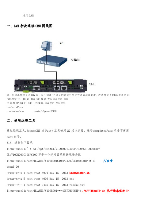
一、LMT初次连接OMU网线图注:左边单独接口为COM口,当不知道IP地址的时候可用此方法调试或查看、右边两口为RJ45普通网口OMU初始IP: 10.71.106.188掩码:255.255.255.128PC电脑IP:10.71.106.189掩码:255.255.255.128omu/mtcaPassroot/mtcaPass admin/eSpaceU2900二、使用远程工具通过远程工具,SecureCRT或Putty工具使用22端口连接,账号:omu/mtcaPass尽量不使用root账号。
(1)、进到如下目录linux-suse11:~ # cd /opt/HUAWEI/V100R001C10SPC400/SETOMUOMIP/注:V100R001C10SPC400不是一个绝对目录根据现场为组linux-suse11:/opt/HUAWEI/V100R001C10SPC400/SETOMUOMIP # ll //查看total 20-rwxr-xr-x 1 root root 8904 May 15 2013 SETOMUOMIP.shdrwxr-xr-x 5 root root 4096 May 15 2013 env-rwxr--r-- 1 root root 3465 May 15 2013 readme.txtlinux-suse11:/opt/HUAWEI/V100R001***/SETOMUOMIP #./SETOMUOMIP.sh 执行脚本修改IP以下为自动初始化过程,无需操作Get the user's passwd is successful ...------------------------------------------------------------Tool for setting omu virtual IP in huawei CDERelease 1.0Copyright 2004-2014 Huawei Technologies Co., Ltd.All rights reserved.NOW START TO MODIFY OMU VIRTUAL IP.------------------------------------------------------------The omu server will be stop in 6 seconds ! Press 'Ctrl + C' to break.Stopping OMU Checkerdone Stopping OMU Monitordone Stopping Mirrordone Stopping OMU Servicesdone Mirror and OMU are stopped successfully.自动初始化过程,成功。
ACEPOILT设表软件安装注册使用说明
ACE POIL T 设表软件现场使用指导目录ACE POILT设表软件现场使用指导 (1)1.ACE POILT 软件安装 (1)2.ACE PILOT软件注册 (4)3. 软件各功能模块概述 (7)✧ 3.1M ETER (7)✧ 3.2C ONFIGURATIONS (8)✧ 3.3U SER L IST (9)✧ 3.4P ERMISSIONS (9)✧ 3.5S ETUP (10)✧ 3.6T OOLS (11)4. 电表设置方案Configuration概括 (14)5. 电表的整体复位 (17)6. ACEPOILT新设表软件电能表方案导入 (18)✧ 6.1.现场接线 (18)✧ 6.2.使用软件导入配置文件 (18)✧ 6.2.1读表口配置 (18)✧ 6.2.2导入电能表配置 (19)✧ 6.2.3电能表配置写入 (21)7.常用操作简述 (25)✧7.1.电能表清零 (25)✧7.2.费率修改 (25)✧7.3.电能表对时 (26)✧7.4.电能表显示内容修改 (26)1.ACE POILT 软件安装1双击软件图标,进行软件安装。
2点击INSTALL进行安装。
3.点击NEXT。
4. 选择I accept,点击NEXT。
5. 修改用户名或不修改,点击NEXT。
6.选择安装目录(建议默认),点NEXT。
7.点击install。
8.点击FINISH完成软件的安装。
2.ACE PILOT软件注册1.在开始菜单内找到ACE PILOT下的ACE PILOT License Mananger,点击进入。
2.点击“Add a new license”。
3.选择license文件,点击打开,完成license导入。
4.回到该界面,点击“Copy License information into the clipboard”将License信息复制入粘贴板,新建文本文档,将License信息粘贴入文档内,发给埃创工程师申请注册码。
C++网络开发包ACE环境的配置与调试
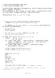
编译client中遇到的问题
二、解压缩后放在D盘
D:\ACE_wrappers
三、在D:\ACE_wrappers\ace目录下新建文件config.h加入一行
#include "ace/config-win32.h"
四、编译:用VC6.0打开D:\ACE_wrappers\ace\ace.dsw
我的系统环境是:Win2k pro(sp4)、VC6.0 (sp5)
一、ACE官方主页:/~schmidt/ACE.html
下载地址:/Download.html
我下载的是Latest Beta Kit中的ACE.zip(Latest Release中的压缩包好像有问题,我有WinRAR3.30解压缩报错)
左侧显示 ACE DLL classes
ACE LIB classes
或1、从菜单上选择“编译”,“放置可远行配置”,选择你需要的工程配置
“编译”,“重建全部”(或任一,如ACE DLL - Win32 MFC Debug)
同样打开ace_static.dsw
编译
ACEs.lib
ACEsd.lib
ACE_RMCasts.lib
ACE_RMCastsd.lib
TMCasts.lib
TMCastsd.lib
ACE生成的dll和lib文件的命名规则:(d = debug,s = static)
(clients.exe较适合发布)
测试 clients 127.0.0.1 1919
DCM4CHEE-ARC-5.10.4安装与配置指南
DCM4CHEE-ARC-5.10.4安装与配置指南目录一、安装资源准备 (3)1.1 资源说明 (3)1.2 资源下载 (3)1.3 安装路径 (3)二、环境变量设置 (4)三、安装步骤 (4)3.1 安装JDK Toolkit (4)3.1.1 下载安装包 (4)3.1.2 安装JDK (4)3.3.3 设置环境变量 (6)3.2数据库安装与初始化 (7)3.2.1 MySQL数据库安装 (7)3.2.2 初始化DCM4CHEE数据库 (9)3.3 安装LDAP服务器 (11)3.3.1 安装ApacheDS服务器并启动服务 (11)3.3.2 安装Apache Directory Studio管理工具 (13)3.6 配置LDAP服务器 (14)3.6.1 创建LDAP连接 (14)3.6.2 导入 LDAP模式 (16)3.6.3 修改LDAP分区信息(无需修改) (17)3.6.4 新建LDAP分区 (18)3.6.5 导入DCM4CHEE默认配置 (18)3.6.6 配置 Archive 的应用实体(AE Title) (19)3.6.7 配置DICOM存储路径 (21)3.7 设置WildFly 服务器 (21)3.7.1 安装WildFly服务器 (21)3.7.2 添加DCM4CHEE配置文件 (21)3.7.3 安装DCM4CHEE的JBOOS组件 (21)3.8 启动WildFly服务器 (23)3.8.1 启动WildFly服务器 (23)3.8.2 验证WildFly服务 (23)3.8.3 创建WildFly用户 (24)3.8.4 WildFly配置界面 (26)3.8.5 WildFly网络访问 (26)3.9 配置器数据源 (27)3.9.1 添加JDBC驱动 (27)3.9.2 创建数据源 (27)3.10 创建JMS 消息队列 (28)3.11 managed-executor-services配置 (29)3.12 设置Device Name名称 (30)3.13 部署DCM4CHEE ARCHIVE (30)3.13.1 部署与取消 (30)3.13.2 启动DCM4CHEE (30)3.13.3 验证DCM4CHEE (31)四、DCM4CHEE配置 (31)4.1 DCM4CHEE AEs 配置 (31)4.1.1 使用WEB UI配置 (31)4.1.2 使用LDAP配置 (31)4.2 远程应用实体(AE)配置 (32)4.2.1 通过WEB UI配置 (32)4.2.2 通过LDAP配置 (33)4.3 文件存储路径配置 (35)五、WildFly网络服务 (35)5.1 WildFly网络访问 (35)一、安装资源准备1.1 资源说明1.2 资源下载1.3 安装路径二、环境变量设置三、安装步骤3.1 安装JDK Toolkit3.1.1 下载安装包不管是32位还是64位Win7/Server系统,必须安装32位的JDK,JAI Image IO 1.2 作为JBOSS组件时不支持Win64位系统和Mac OS X系统,若安装成64位JDK,则WADO的图像解析将出现不支持图像解析器的问题。
ArcSight Express 4.0虚拟应用程序安装与配置指南说明书
Installation and Configuration Guide ArcSight Express 4.0 Virtual ApplianceMarch 31, 2014Copyright © 2014 Hewlett-Packard Development Company, L.P.Confidential computer software. Valid license from HP required for possession, use or copying. Consistent with FAR 12.211 and 12.212, Commercial Computer Software, Computer Software Documentation, and Technical Data for Commercial Items are licensed to the U.S. Government under vendor's standard commercial license. The information contained herein is subject to change without notice. The only warranties for HP products and services are set forth in the express warranty statements accompanying such products and services. Nothing herein should be construed as constituting an additional warranty. HP shall not be liable for technical or editorial errors or omissions contained herein.Follow this link to see a complete statement of copyrights and acknowledgements:/copyrightThe network information used in the examples in this document (including IP addresses and hostnames) is for illustration purposes only.HP ArcSight products are highly flexible and function as you configure them. The accessibility, integrity, and confidentiality of your data is your responsibility. Implement a comprehensive security strategy and follow good security practices.This document is confidential.Contact InformationPhone A list of phone numbers is available on the HP ArcSight TechnicalSupport page: /us/en/software-solutions/software.html?compURI=1345981#.URitMaVwpWI. Support Web Site Protect 724 Community https://Revision HistoryDate Product Version Description03/31/2014 1.0First release of guide and virtual applianceContentsChapter 1: Overview (5)Chapter 2: Installing the ArcSight Express Virtual Appliance (7)Supported ESXi Version and Required Hardware (7)Operating System (7)FIPS Support (8)Browser Support (9)Downloading the ArcSight Express Virtual Appliance OVA Files (9)Upgrade Support (9)Deploying the ArcSight Express Virtual Appliance OVA File (9)Installing a License File (13)Confidential AE Virtual Appliance Installation and Configuration Guide 3Contents4 AE Virtual Appliance Installation and Configuration Guide ConfidentialChapter 1OverviewThe ArcSight Express Virtual Appliance is a Security Information and Event Management(SIEM) solution that collects and analyzes security data from heterogeneous devices onyour network and provides you a central, real-time view of the security status of all devicesthat are of interest to you.ArcSight Express components gather and store events generated by the devices youidentify. These events are filtered and correlated with events from other devices orcollection points to discover risks and assess vulnerabilities.ArcSight Express uses the Correlation Optimized Retention and Retrieval Engine Storage(CORR-Engine Storage), a proprietary data storage and retrieval framework that receivesand processes events at high rates, and performs high-speed searches. This provides anumber of benefits, including increased performance and more compact data storage.The ArcSight Express Virtual Appliance allows deployment of ArcSight Express on serversthat have VMware ESXi installed.Confidential AE Virtual Appliance Installation and Configuration Guide 51 Overview6AE Virtual Appliance Installation and Configuration Guide ConfidentialConfidential ArcSight Express Virtual Appliance Installation and Configuration Guide 7Chapter 2Installing the ArcSight Express Virtual ApplianceThe following topics are covered in this chapter:Supported ESXi Version and Required HardwareThe ArcSight Express Virtual Appliance is supported on VMware ESXi 5.5. The hardware requirements for installing the ArcSight Express Virtual Appliance OVA file are:⏹12 CPU cores ⏹36 GB of RAM ⏹ 1.8 TB disk availableOperating SystemThe ArcSight Express Virtual Appliance operating system is Centos 6.2 and the following security patches:⏹bind-libs-9.8.2-0.17.rc1.el6_4.4.x86_64.rpm ⏹bind-utils-9.8.2-0.17.rc1.el6_4.4.x86_64.rpm ⏹cups-1.4.2-50.el6_4.4.x86_64.rpm ⏹cups-libs-1.4.2-50.el6_4.4.x86_64.rpm ⏹cvs-1.11.23-15.el6.x86_64.rpm ⏹dbus-glib-0.86-6.el6.x86_64.rpm ⏹dhclient-4.1.1-34.P1.el6.centos.x86_64.rpm ⏹dhcp-common-4.1.1-34.P1.el6.centos.x86_64.rpm ⏹freetype-2.3.11-14.el6_3.1.x86_64.rpm ⏹ghostscript-8.70-15.el6_4.1.x86_64.rpm“Supported ESXi Version and Required Hardware” on page 7“Operating System” on page 7“Browser Support” on page 9“Downloading the ArcSight Express Virtual Appliance OVA Files” on page 9“Deploying the ArcSight Express Virtual Appliance OVA File” on page 9“Installing a License File” on page 132 Installing the ArcSight Express Virtual Appliance⏹krb5-appl-clients-1.0.1-7.el6_2.1.x86_64.rpm⏹krb5-libs-1.10.3-10.el6_4.2.x86_64.rpm⏹krb5-workstation-1.10.3-10.el6_4.2.x86_64.rpm⏹liberation-fonts-common-1.05.1.20090721-5.el6.noarch.rpm⏹liberation-sans-fonts-1.05.1.20090721-5.el6.noarch.rpm⏹libexif-0.6.21-5.el6_3.x86_64.rpm⏹libjpeg-turbo-1.2.1-1.el6.x86_64.rpm⏹libpng-1.2.49-1.el6_2.x86_64.rpm⏹libproxy-0.3.0-4.el6_3.x86_64.rpm⏹libproxy-bin-0.3.0-4.el6_3.x86_64.rpm⏹libproxy-python-0.3.0-4.el6_3.x86_64.rpm⏹libsmbclient-3.6.9-151.el6.x86_64.rpm⏹libtalloc-2.0.7-2.el6.x86_64.rpm⏹libtdb-1.2.10-1.el6.x86_64.rpm⏹libtiff-3.9.4-9.el6_3.x86_64.rpm⏹libvorbis-1.2.3-4.el6_2.1.x86_64.rpm⏹libxml2-2.7.6-12.el6_4.1.x86_64.rpm⏹libxml2-python-2.7.6-12.el6_4.1.x86_64.rpm⏹nspr-4.9.2-1.el6.x86_64.rpm⏹nss-3.14.0.0-12.el6.x86_64.rpm⏹nss-sysinit-3.14.0.0-12.el6.x86_64.rpm⏹nss-util-3.14.0.0-2.el6.x86_64.rpm⏹openjpeg-libs-1.3-9.el6_3.x86_64.rpm⏹openssl-1.0.0-27.el6_4.2.x86_64.rpm⏹perl-5.10.1-131.el6_4.x86_64.rpm⏹perl-libs-5.10.1-131.el6_4.x86_64.rpm⏹perl-Module-Pluggable-3.90-131.el6_4.x86_64.rpm⏹perl-Pod-Escapes-1.04-131.el6_4.x86_64.rpm⏹perl-Pod-Simple-3.13-131.el6_4.x86_64.rpm⏹perl-version-0.77-131.el6_4.x86_64.rpm⏹pixman-0.26.2-5.el6_4.x86_64.rpm⏹samba-client-3.6.9-151.el6.x86_64.rpm⏹samba-common-3.6.9-151.el6.x86_64.rpm⏹samba-winbind-3.6.9-151.el6.x86_64.rpm⏹samba-winbind-clients-3.6.9-151.el6.x86_64.rpm⏹sudo-1.8.6p3-7.el6.x86_64.rpm⏹xulrunner-17.0.6-2.el6.centos.x86_64.rpm⏹yelp-2.28.1-17.el6_3.x86_64.rpmFIPS SupportFIPS is not supported for this release of the virtual appliance.8ArcSight Express Virtual Appliance Installation and Configuration Guide Confidential2 Installing the ArcSight Express Virtual ApplianceConfidential ArcSight Express Virtual Appliance Installation and Configuration Guide 9Browser SupportSupported browsers for connecting to the ESM Manager are:⏹Internet Explorer 9 and 10⏹Firefox 24Downloading the ArcSight Express Virtual Appliance OVA FilesThe ArcSight Express Virtual Appliance OVA files are available for download from the HPSoftware Depot at: .If you use Internet Explorer to download the files, ensure that the files names remain asshown below.Download the 3 files and the MD5 checksum to a disk accessible by your vSphere client:⏹B7500_B1312_1800GB_V8.ova.part1 ⏹B7500_B1312_1800GB_V8.ova.part2 ⏹B7500_B1312_1800GB_V8.ova.part3Join the 3 files into one file by running one of the following commands:Windows - copy /bB7500_B1312_1800GB_V8.ova.part1+B7500_B1312_1800GB_V8.ova.part2+B7500_B1312_1800GB_V8.ova.part3 B7500_B1312_1800GB_V8.ovaLinux - cat B7500*.part* > B7500_B1312_1800GB_V8.ovaAfter joining the 3 files together , use the MD5 checksum to verify the file’s integrity.Upgrade SupportThe ArcSight Express 4.0 Virtual Appliance cannot be upgraded from any prior versions ofArcSight Express.Deploying the ArcSight Express Virtual Appliance OVA FileTo deploy the virtual appliance OVA file, use a vSphere client to perform the followingprocedure:2 Installing the ArcSight Express Virtual Appliance10 ArcSight Express Virtual Appliance Installation and Configuration Guide Confidential 1Select File > Deploy OVF Template . The Source screen displays: 2Click Browse and navigate to where you downloaded the OVA file.3Select the file and then click Next . The OVF Template Details screen displays:4Click Next. The Name and Location screen displays:5Enter a name for the virtual appliance or accept the default. You can change the name later. Click Next. The Storage screen displays:6Select a drive with 1.8 TB of disk space. The virtual appliance requires 1.8 TB of disk space. Click Next. The Disk Format screen displays:7Select the Thick Provisioned Lazy Zeroed Format. Click Next. The Ready to Complete screen displays.8If the deployment settings are correct, click Finish. A progress timer will appear showing the progress of the deployment. When the deployment completes, the virtualmachine created from the OVA file is added to the inventory (Virtual Machines tab) onyour vSphere client.9Right-click your VM and select Power > Power Off.10Before running the First Boot Wizard, configure your network settings and increase the memory from 12 GB to 36 GB. To configure the network settings and increase thememory for your virtual appliance, right-click your virtual machine in the VirtualMachines tab. Select Edit Settings.After configuring the network settings and increasing the memory for your virtual machine,select Power > Power On. The virtual machine performs an initial boot process thatdisplays in the console. After installing the license, refer to the Configuring the ArcSightExpress chapter of the ArcSight Express with CORR-Engine 4.0 Configuration Guide. Theguide is available at:https://Installing a License FileThe ArcSight Express Virtual Appliance requires that a license be installed.Perform the following procedure to install the license:1Download the license file from the Customer Support web site at to a computer from which you can connect to thevirtual appliance.2Follow the First Boot Wizard directions for license installation.3Click Browse and navigate to where you stored the license and select the license file.4Click Upload & Install.5Perform the rest of the First Boot Wizard steps.The base license includes:⏹ 4 onboard connectors⏹25 remote connectors⏹ 3 console users⏹25 web users⏹2500 IDView users⏹1500 devices⏹25000 assets⏹Threat detector enabledThe base license includes 250 sustained events-per-second (EPS). Additional EPS can beadded only in increments of 250 up to a maximum of 1250.Pattern Discovery jobs can be resource intensive. Under high EPS, Pattern Discovery jobscan cause a degradation in performance, and may fail to return a matching result set.ArcSight recommends that you reduce the number of events over which the PatternDiscovery search runs and/or frequency of Pattern Discovery jobs when running a systemwith high EPS.。
ACOINFO RealEvo -Simulator 使用手册说明书
RealEvo-Simulator使用手册Product Manual产品使用手册 Copyright (c) 2015-2018 ACOINFO Inc. All rights reserved.i修订历史产品使用手册 Copyright (c) 2015-2018 ACOINFO Inc. All rights reserved.i目 录第1章 概述 ........................................................................................... 1 第2章 功能介绍 . (2)2.1安装RealEvo-Simulator ·········································································· 2 2.2 打开RealEvo-Simulator ·········································································· 2 2.3 切换语言····························································································· 3 2.4RealEvo-Simulator 内置虚拟机 ................................................................. 4 2.4.1 leon3-sparc 配置信息 ........................................................................ 4 2.4.2 mini2440配置信息 .......................................................................... 5 2.4.3 mipsr4k 配置信息 ............................................................................ 6 2.4.4 ppc750配置信息 ............................................................................. 7 2.4.5 x86配置信息 ................................................................................. 8 2.4.6 zynq-a9配置信息 ............................................................................ 9 2.5 运行内置虚拟机(mini2440) ................................................................. 10 2.6 新建虚拟机(mini2440) ....................................................................... 11 2.7 打开虚拟机(mini2440) ....................................................................... 16 2.8 新建调试(mini2440) .......................................................................... 17 2.9 开始调试(mini2440) .......................................................................... 21 2.10 选项对话框功能 . (23)2.10.1 创建虚拟网络适配器 ...................................................................... 24 2.10.2 设置IP 地址 ................................................................................. 25 2.10.3 删除虚拟网络适配器 . (25)附录 (27)创建x86虚拟机 (27)产品使用手册 Copyright (c) 2015-2018 ACOINFO Inc. All rights reserved.1第1章 概述本文档适用于使用SylixOS 开发的工程师,本文将着重讲述配套RealEvo 开发套件的RealEvo-Simulator 虚拟机套件的功能及其使用方法。
Sun Ray 服务器软件 2.0 管理员指南说明书

Sun Microsystems, Inc.4150 Network CircleSanta Clara, CA 95054 U.S.A. 650-960-1300Sun Ray™ 服务器软件2.0 管理员指南部件号:817-0263-102003 年 2 月,修订版 A请将有关本文档的意见或建议发送至:*******************Copyright 2002, 2003 Sun Microsystems, Inc., 4150 Network Circle, Santa Clara, California 95054, U.S.A. 版权所有。
Sun Microsystems, Inc. 对此产品中所包含的相关技术拥有知识产权。
在特殊且不受限制的情况下,这些知识产权可能包括/patents上列出的一个或多个美国专利,以及美国和其它国家的一个或多个其它专利或待决的专利申请。
本产品或文档按照限制其使用、复制、分发和反编译的许可证进行分发。
未经 Sun 及其许可证颁发机构的书面授权,不得以任何方式、任何形式复制本产品或本文档的任何部分。
第三方软件,包括字体技术,由 Sun 供应商提供许可和版权。
本产品的某些部分从 Berkeley BSD 系统派生而来,经 University of California 许可授权。
UNIX 是在美国和其它国家注册的商标,经 X/Open Company, Ltd. 独家许可授权。
Sun、Sun Microsystems、Sun 徽标、Sun Ray、Sun WebServer、Sun Enterprise、Ultra、UltraSPARC、SunFastEthernet、Sun Quad FastEthernet、Java、JDK、HotJava 以及 Solaris 是 Sun Microsystems, Inc. 在美国和其它国家的商标、注册商标或服务标记。
AceSure安装配置手册

文档来源为:从网络收集整理.word版本可编辑.欢迎下载支持.AceSure安装配置手册1文档收集于互联网,如有不妥请联系删除.文档来源为:从网络收集整理.word版本可编辑.欢迎下载支持.目录1. 管理平台安装配置 (1)1.1 管理平台操作系统搭建 (1)1.2 安装/卸载服务端 (1)1.3 初始化服务端 (4)2. 存储节点、计算节点安装配置 (7)2.1 安装/卸载存储节点、计算节点 (7)2.2 配置存储节点、计算节点 (8)3. 客户端安装配置 (10)3.1 兼容性列表 (10)3.2 安装/卸载客户端 - L INUX 系统 (11)3.3 安装/卸载客户端 - W INDOWS 系统 (15)4. 附录 (16)4.1 管理平台 (16)4.2 存储/计算节点 (17)4.3 客户端 (17)2文档收集于互联网,如有不妥请联系删除.1. 管理平台安装配置1.1 管理平台操作系统搭建➢服务器操作系统:CentOS 7.0.1406 x64➢操作系统安装要求:✧方法1:按照LINUX 标准安装程序进行,需选择安装的软件如下图1.1-1 所示。
图1.1-1✧方法2:使用数腾研发部提供的CentOS 7 一键安装版本进行安装,安装过程无需人工干预。
1.2 安装/卸载服务端注:如果使用方法2 安装CentOS 操作系统,可直接跳至步骤三。
➢升级安装的时候,如从版本1 升级到版本2,有两种方式。
✧使用升级命令参数安装:rpm -Uvh --nodeps 版本2rpm 包名称。
✧先卸载版本1,再安装版本2。
➢如果是安装同一个版本的新包,或旧版本rpm 包,请先卸载当前的安装包,否则无法安装。
➢ 不要手动删除6.0 下的安装目录。
步骤一:安装服务端前,使用shell 工具登录到服务端,进入cd /etc/selinux/目录,使用vim config 命令查看config 文件,确认“SELINUX=disabled”,若不是,则修改并重启服务端,如下图1.2-1所示。
- 1、下载文档前请自行甄别文档内容的完整性,平台不提供额外的编辑、内容补充、找答案等附加服务。
- 2、"仅部分预览"的文档,不可在线预览部分如存在完整性等问题,可反馈申请退款(可完整预览的文档不适用该条件!)。
- 3、如文档侵犯您的权益,请联系客服反馈,我们会尽快为您处理(人工客服工作时间:9:00-18:30)。
AceSure
安装配置手册
目录
1. 管理平台安装配置 (1)
1.1 管理平台操作系统搭建 (1)
1.2 安装/卸载服务端 (1)
1.3 初始化服务端 (4)
2. 存储节点、计算节点安装配置 (7)
2.1 安装/卸载存储节点、计算节点 (7)
2.2 配置存储节点、计算节点 (8)
3. 客户端安装配置 (10)
3.1 兼容性列表 (10)
3.2 安装/卸载客户端-L INUX系统 (11)
3.3 安装/卸载客户端-W INDOWS系统 (15)
4. 附录 (16)
4.1 管理平台 (16)
4.2 存储/计算节点 (17)
4.3 客户端 (17)
图1.1-1
✧方法2:使用数腾研发部提供的CentOS7一键安装版本进行安装,安装过程无需人工干
预。
图1.2-1
步骤二:进入cd/etc/libvirt/目录,使用vimqemu.conf命令,修改如下图1.2-2所示的三处地方:
图1.2-2
步骤三:导入cdapserverrpm安装和Dependent依赖文件夹至安装管理平台的服务器,以
图1.2-5
步骤六:以版本6.0.3.0001为例,执行命令:rpm-ivh--nodepscdap_server-6.0.3.0001-1.x86_64.rpm
图1.2-6
图1.2-7
1.3初始化服务端服务端安装成功后将执行一次初始化服务端操作,对服务端进行必要的配置。
其步
图1.3-2
步骤三:管理员配置。
如下图1.3-3所示,该页面为用户提供管理模式及管理员密码的初始化配置
点击“下一步”。
AceSure系统默认为仅一名超级管理员admin,若勾选“启动三元管理员模式”则由超级管理员admin、审计管理员auditor、安全管理员security共同管理AceSure系统,并需要为他们设置初始密码、电子邮箱;
图1.3-3
步骤四:网络配置。
如下图1.3-4所示,请手动填写服务端IP地址,该项默认可填入两个果有更多IP地址,可在完成初始化后进入系统设置添加。
点击“完成”。
图1.3-5 存储节点、计算节点安装配置
图2.1-2
步骤四:执行命令rpm-e--nodepscdap_storage_and_compute进行卸载,如下图2.1-3所示,出现enduninstall说明卸载成功。
图2.1-3
配置存储节点、计算节点
若存储节点、计算节点与管理平台安装在不同的服务器下,则需要修改存储节点配置、计算节点
图2.2-1 步骤2:修改后需要重启服务。
图3.2-1
步骤二:如下图3.2-2所示,用户在客户端列表中选择下载匹配的应急客户端安装包,并解压缩保存。
图3.2-3
图3.2-3 图3.2-4
图3.2-6。
