A接触器辅助触头安装手册
A63-30-11交流接触器
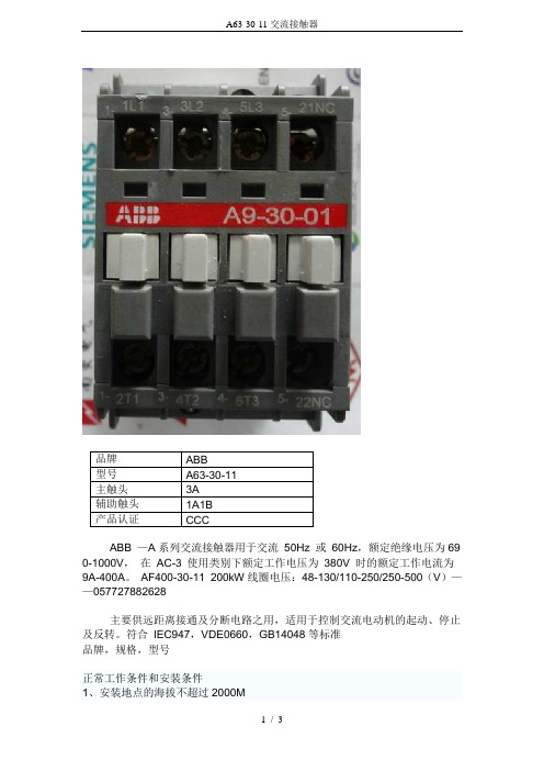
2、周围空气温度不超过+40度,且其25H内的平均温度值不超过=35度,周围空气温度下限值为-5度3、安装地点的空气相对温度在最高+40度时不超过50%,在较低温度时可允许有较高的相对温度,例如20度时达90%,对由于温度变化偶尔产生的凝露应采取特殊措施。
4、安装地点的污染等级为3级5、接触器允许垂直或水平安装,当垂直安装时,安装而与垂直的倾斜度不大于正负30%ABB交流接触器A9-30-01 线圈电压(V):24/110/220/380ABB交流接触器A9-30-10线圈电压(V):24/110/220/380ABB交流接触器A12-30-01 线圈电压(V):24/110/220/380ABB交流接触器A12-30-10线圈电压(V):24/110/220/380ABB交流接触器A16-30-01线圈电压(V):24/110/220/380ABB交流接触器A16-30-10线圈电压(V):24/110/220/380ABB交流接触器A26-30-01线圈电压(V):24/110/220/380ABB交流接触器A26-30-10线圈电压(V):24/110/220/380ABB交流接触器A30-30-01线圈电压(V):24/110/220/380ABB交流接触器A30-30-10线圈电压(V):24/110/220/380 ABB交流接触器A40-30-10线圈电压(V):24/110/220/380 ABB交流接触器A40-30-01线圈电压(V):24/110/220/380 ABB交流接触器A50-30-11线圈电压(V):24/110/220/380 ABB交流接触器A63-30-11线圈电压(V):24/110/220/380 ABB交流接触器A75-30-11线圈电压(V):24/110/220/380 ABB交流接触器A95-30-11线圈电压(V):24/110/220/380 ABB交流接触器A110-30-11线圈电压(V):24/110/220/380 ABB交流接触器A145-30-11线圈电压(V):24/110/220/380 ABB交流接触器A185-30-11线圈电压(V):24/110/220/380 ABB交流接触器A210-30-11线圈电压(V):24/110/220/380 ABB交流接触器A260-30-11线圈电压(V):24/110/220/380 ABB交流接触器A300-30-11线圈电压(V):24/110/220/380 ABB交流接触器A320-30-11线圈电压(V):24/110/220/380。
Contactor A201 电气接触器说明说明书

The ContactorA201 contactors are designed for the control of inductive or non-inductive loads at voltages between 120 and 600, AC_ The units are suitable for mounting on either steel or insulated pan-els. All parts are front removable. Contactors should be pro-tected against short circuits by branch circuit protective devices selected in accordance with the National Electrical Code (NEC).This industrial type control is designed to be installed, oper-ated, and maintained by adequately trained workmen. These instructions do not cover all details, variations, or combinations of the equipment, its storage, delivery, installation, check out, safe operation, or maintenance. Care must be exercised to comply with local, state, and national regulations, as well as safety practices, for this class of equipment.Two-pole contactors have the same current ratings as three-pole devices but are not suitable for controlling three-phase motors.CONTROLLER RATINGS - 3 POLE CONTACTOR Size 2 Horsepower Ratings Single Phase Three Phase 115V 230V 220V 230V 380V 460/575V 3 71/2 10 15 25 25Size 2 Current RatingsContinuous Maximum Carrying Inrush Current Current, RMS (Amps, Peak, (Resistive Load) including Open Enclosed offset) 50A 45A 483AFig. 1 Size 2, A201 Non-reversing Contactor Fig. 2 Size 2, A211 Reversing ContactorA201, A211, A251, Size 2 Magnetic Contactor Nonreversing or ReversingFig. 3 Dimension Drawings (Dim. in inches)Auxiliary Contacts - T ype JA J20 with two normally-open poles is supplied’ mounted in the upper left hand corner recess of nonreversing contactors. One pole is used as the holding circuit auxiliary. Two J11 units are supplied mounted on reversing contactors. A maximum of four auxiliary units can be in-stalled in each non-reversing contactor (three in each reversing contac-tor) with terminals either in line or in a right angle relationship to the power poles. Type J auxiliary contacts mount by means of a spring clip and retainer screw. To remove the unit rotate the retainer screw several times (counterclockwise) and then slide the auxiliary contact unit out of the recess.TYPE J - AUXILIARY CONTACTSContact T ype Catalog No.2 Normally Closed J022 Normally Open J201 Normally Open and 1 Normally Closed J111 Normally Open and 1 NormallyClosed, DB* J1CTYPE J CONTACT RATINGS (A600, R300)Voltage Continuous Make Break 120-600 VAC 10A 7200VA 720VA 72-120 VAC 10A 60A 720VA 2B-72 VAC 10A 60A 10A 2B-300 VDC 1.0A 28VA 28VA *DB - Delayed BreakTABLE I - ACCESSORIESFuse Block Kits - Meet requirements of NEC concerning common control fusing.OrderCat No. Qty. DescriptionFS6 2 Contactor mounted Fuse Holder for 1 600 volt Bussman KTK Fuse FKR 1 Panel mounted Fuse Holder for 2 Class CC (Bussman KTKR) Fuses **Use when available fault current exceeds 10,000 amperes.Order Fuses Separately By Ampere Rating.Controller Minimum Wire Suggested Size Size in Control Circuit Fuse Size 2 #16 AWG 10 AMP When using a control transformer, select fuse size per the Na- tional Electrical Code.Mechanical InterlockType M-33 and M-34 mechanical interlocks are used when a pair of contactors must be mechanically protected against the closing of one when the other is already closed. The two contactors may be mounted side-by-side (A211, horizontal confi guration) or one above the other (A251 , vertical confi guration). The two contactors may be any com-bination of pole arrangements. Type M-33 mechanical interlocks are provided with A211 reversing contactors and Type M-34 interlocks with A251 reversing contactors. These interlocks occupy one recess in each contactor.CoilA201 contactors are available with a single or dual voltage coil. When equipped with a single voltage coil, the contactor is wired as shown in Figure 5. A connection diagram for a dual voltage coil is shown in Fig-ure 4. When suppliedwith a dual voltage coil, thecontactor is normally wired for the higher voltage connection. The wiring may be changed to the lower voltage connection by removing and reconnecting the jump-ers as illustrated below.AC COIL DATA, SIZE 2 (TYPICAL VALUES)Poles Inrush VA Sealed VA Sealed Watts 2-3 160 25 7.8 4-5 200 30 9.5Pickup Time: 14-32 ms Dropout Time: 12-16 msREPLACEMENT COIL: ORDER BY PART NUMBER,VOLTAGE, AND FREQUENCYSIZE 2 AC OPERATING COILSVoltage 24120/1102082402773804801440600120/240*2401480*Freq. 6060/50 60 60 60 5060/50 6060/6060/604 and5 pole Not Available 505C818G01505C818G02505C818G12505C818G16505C818G07505C818G13505C818G05505C818G10505C818G03POWER CIRCUIT TERMINALSNEMA Size Wire Size 2 #14 - 3 AWGWire with 75o C. copper conductors only.Short-Circuit Withstand RatingsCalculate the fault current available at the point where the contactor is to be installed. Select a shortcircuit protective device with an interrupt-ing rating suffi cient for the system voltage and available fault current within the limits shown in Table II. This controller is suitable for use with the SCPD’s shown in Table II up to the limits shown.Fig. 4 Dual Voltage Coil Connections33L VHVCONNWCTIONSFOR LOWER VOLTAGECONNWCTIONSFOR HIGHER VOLTAGE2 and3 pole 505C806G16505C806G01505C806G02505C806G12505C806G18505C806G07505C806G13505C806G05505C806G10505C806G03* Dual Voltage Coils. Use only on starters originally supplied with a dual voltage coil2Instruction Publication IL16961Effective April 2011A201, A211, A251, Size 2Magnetic Contactor Nonreversing or ReversingEATON CORPORATION TABLE II - SHORT -CIRCUIT WITHSTAND RATINGSShort-Circuit Protective Device (SCPD)Max.Rating SCPD Circuit Breaker Interrupting RatingShort-Circuit Rating Typical Disconnect Device Cat No.Current Voltage Class H Fuse100A -----5,000A 600V DS263Class J Fuse 100A -----100,000A 600V DS263Class R Fuse 100A -----100,000A 600V DS263Class T Fuse 100A -----100,000A 600V DS263Magnetic Only 1Type CB250A*Marked HMCP 100,000A 480V HMCP 50,000A 600V Thermal/Mag.Type CB 390A65,000A65,000A 480V HFD 25,000A25,000A 600V HFD 100,000A 100,000A 480V FOC 35,000A35,000A 600V FOC Mag. Only TypeCB+ CL 450A*HMCP+Current Limiter 100,000A600VHMCP+EL Thermal/Mag.Type CLB 590A 150,000A100,000A 480V FCL1 Instantaneous Adjustable Trip 2Circuit Breaker 3 lnverse-Time Circuit Breaker.4 Instantaneous Adjustable Trip with Current-Limiting Attachment.5 lnverse-Time Current-Limiting Breaker.*To comply with the NEC, thermal overload relays must be included in the branch circuit.3STARTSTOPFWDFWDREVREVSTOPSTOP213324515211STARTSTOP3LOW VOLTAGE PROTECTION WITH 3 WIRE PUSHBUTTON START -STOP OPERATIONSINGLE CIRCUIT PUSHBOTTON LOW VOLTAGE PROTECTIONDOUBLE CIRCUIT PUSHBOTTON LOW VOLTAGE PROTECTIONLOW VOLTAGE RELEASE WITH 3 WIRE PUSHBUTTON START -STOP OPERATIONREVERSINGNONREVERSINGContact Kit Part Number 2 Pole Size 2 3738331G113 Pole Size 2 3738331G124 Pole Size 2 3738331G135 Pole Size 2 3738331G14Mechanical Interlock Cat. No. For Horizontal Reversing (A211) M-33-2 For Vertical Reversing (A251) M-34-2Fig. 7 Connection Diagram, A251Fig. 8 Control Station Diagrams3Instruction Publication IL16961Effective April 2011A201, A211, A251, Size 2Magnetic Contactor Nonreversing or ReversingEATON CORPORATION Maintenance - First T urn Off Power T o Inspect ContactsRefer to Figure 9. Loosen the two arc box assembly screws (7) located immediately above and below the nameplate and remove the arc box (8). Contacts (5) are visible. Retighten the screws per Table IV .T o Replace ContactsAfter removing the arc box and with replacement contacts at hand, compress the overtravel spring (12) and remove the moving contact (5) from the crossbar (6). Remove the retaining screw (11) and lift out the stationary contact assembly (14).To replace contacts, reverse the above procedure, making sure that stationary contacts are secure (see Table IV), moving contacts are free to move, overtraveI springs are seated and the crossbar moves freely when the arc box is in position.The silver cadmium oxide contact buttons need NO dressing or lubri-cant throughout their life. Important - Replace all contacts and springs as a group to avoid misalignment.T o Replace The CoilRefer to Figure 9. Loosen the assembly screws (10) located to the im-mediate left and right of the arc box.Pull the loosened upper base structure (9) forward. Pull the coil (1) from the upper base, plug in a new coil, replace the upper base struc-ture and check the auxiliary contacts for secureness when reposition-ing the upper base. Tighten the assembly screws. Refer to Table IV .Magnet - Armature AssemblySelf alignment and permanent air gap features of the magnet armature make replacement unnecessary. Mating pole face-surfaces should-be kept clean.Arc box must be in place when the contactor interrupts a circuit.TABLE IV - RECOMMENDED DRIVING TORQUEDrivingT orque Fig. 9Location (Qty.) (lb.-in.) Item Cover Screw (2) 8--9 7Coil Wire Connector (2) 8--9 13Stationary Contact Screw (2/pole) 18--20 11Main Power Connector (2/pole) 45--50 4Eaton Corporation Electrical Sector 1111 Superior Ave.Cleveland, OH 44114United States877-ETN-CARE (877-386-2273)© 2011 Eaton Corporation All Rights ReservedPublication No. IL16961 / 001April 2011Eaton is a registered trademark of Eaton Corporation.All other trademarks are property of their respective owners.Instruction Publication IL16961Effective April 2011A201, A211, A251, Size 2MagneticContactor Nonreversing or ReversingFig. 9 A201 Magnetic Contactor (Exploded View)。
德力西 OF9辅助触头 使用说明书

符合标准:GB/T 14048.5 安装、使用产品前,请仔细阅读使用说明书并妥善保管、备用安全告知在安装、操作、运行、维护、检查之前,请务必认真阅读本说明书,并按照说明书上的内容准确安装、使用本产品。
危险:●严禁湿手操作辅助触头;●使用中,严禁触摸导电部位;●维护与保养时,必须确保产品不带电;●严禁用短路的办法来测试产品;注意:●安装、维护与保养时,应由具有专业资格的人员操作;●产品的各项特性出厂时已整定,使用中不能自行拆装或随意调节;●使用前请确认产品额定电压、额定电流、频率及特性是否符合工作要求;●为防止相间短路,应对接线端裸露导线或铜母线进行绝缘处理;●如果产品在开箱时有破损或异常响声,应立即停止使用并联系供应商;●本产品不适用于频繁启动的电动机、电热设备、电容柜、高感性或高容性负载和高温环境等特殊场合;●产品报废时,请做好产品废弃物处理,谢谢您的合作。
目录1主要用途及适用范围 (1)2 产品型号及含义、面板介绍 (1)3 正常使用、安装及运输条件 (2)3.1正常使用、安装条件 (2)3.2正常贮存和运输条件 (2)4技术特性 (2)4.1主要技术性能参数 (2)4.2其它技术参数 (2)5 外形及安装尺寸 (3)5.1外形及安装尺寸 (3)5.2接线示意图 (3)6 安装和使用(维护) (4)7 开箱检查 (5)8公司承诺 (5)1主要用途及适用范围OF9系列辅助触头主要用于交流50/60Hz、额定电压不超过415V、额定电流1A~6A的辅助电路中。
此系列辅助触头通过远程接信号灯等方式实现远程显示断路器的分合闸状态。
2 产品型号及含义、面板介绍●产品型号及含义●面板介绍说明:1公司商标 2产品名称 3指示标志 4进线端子 5常闭出线端子 6常开出线端子7技术参数 8拼装示意图 9符合标准 10认证标识 11扭矩、剥线指示及接线端子指示12 敲落孔盖3 正常使用、安装及运输条件3.1正常使用、安装条件a)周围空气温度上限不超过+70℃, 下限不超过-35℃,并且在24小时内平均温度不超过+35℃;b)安装地点的海拔不超过2000m;c)温度为+40℃时,空气的相对湿度不超过50%;在较低温度下允许有较大的相对湿度,例如在+20℃时,相对湿度不超过90%,对由于温度变化偶尔产生的凝露应采取特殊的保护措施;d)辅助触头安装场所附近的外磁场,在任何方向均不应超过地磁场的5倍;e)安装在无爆炸危险的介质中,且介质中无足以腐蚀金属和破坏绝缘的气体与尘埃;f)安装在无显著冲击振动及无雨雪侵袭的地方;g)污染等级:2级;h)安装类别:Ⅱ类、Ⅲ类;i)应安装于配电箱、配电柜或盒中。
接触器附件
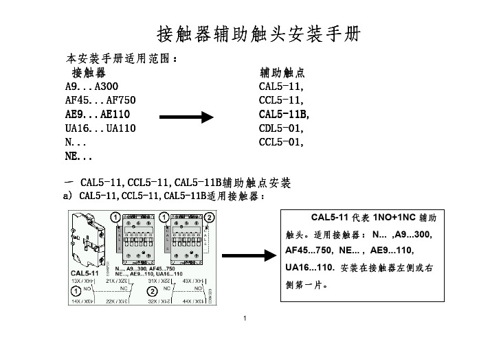
b) CAL5-11,CCL5-11,CAL5-11B辅助触点的安装:
在A(E)9...26,UA16...26,N(E)...上安装CAL5-11, 在A(E)9...16,N(E)...上安装CCL5-11: 将一字形连接件插入第二个连接孔,丢弃工字形连 接件,然后按照j→k→l→m→n步骤安装。
4接触器辅助触头安装手册来自d) CAL5-11,CCL5-11,CAL5-11B辅助触点尺寸及接线端子:
5
接触器辅助触头安装手册
e) CAL5-11,CCL5-11,CAL5-11B与接触器的可能组合:
6
接触器辅助触头安装手册
二 CDL5-01,CCL5-01辅助触点安装
a) CDL5-01,CCL5-01辅助触点安装和拆卸:
按照j→k→l→m→n步骤 安装。
7
接触器辅助触头安装手册
b) CDL5-01,CCL5-01辅助触点电气接线和尺寸:裝
请按照左图所示连接控 制线圈,切勿将A1,A2 错接到A3端子!
8
接触器辅助触头安装手册
注意:
必须由合格的技术人员根据相应技术规范安装标准和安全准则进行 安装调试。在接触器通电以前必须确认控制电压符合支架上所标的 线圈电压标准,否则会损坏线圈。请勿接触带电部分。危险!
9
接触器辅助触头安装手册
本安装手册适用范围: 接触器
A9...A300 AF45...AF750 AE9...AE110 UA16...UA110 N... NE...
辅助触点 CAL5-11, CCL5-11, CAL5-11B, CDL5-01, CCL5-01,
一 CAL5-11,CCL5-11,CAL5-11B辅助触点安装
CCL5-11 代表 1NO+1NC 辅助 触头。适用接触器: N... ,A9...A16,
接触器辅助触点接线方法
接触器辅助触点接线方法说实话接触器辅助触点接线方法这事,我一开始也是瞎摸索。
我最初就看着那些触点和线,一头雾水。
我试过直接按照自己想象的方式接,觉得只要把线连上应该就差不多,结果根本不行啊。
接触器就是不按照我想的那样工作,当时特别沮丧,感觉这些线就像一群调皮的小虫子,我怎么都指挥不好它们。
后来我就认认真真地去看书去查资料。
我发现接触器一般都有主触点和辅助触点。
辅助触点呢,又分为常开和常闭。
这就好比门啊,常开触点就像是平时开着的门,常闭触点就是平时关着的门。
我说说我接线时候的实际操作哈。
对于常开辅助触点接线,如果我想让它在接触器吸合的时候干点啥,比如说导通一个小电路给个信号。
我就把线一端接到常开触点的一端,这里就像给小虫子安排了一个起点,然后把另一端接到我需要它供电或者传输信号的地方,就像是终点。
这中间千万要注意线的连接要牢固,我就有一次没接好,总是时断时续的。
常闭辅助触点接线也类似呢。
不过它的作用不一样,比如说有时候作为互锁用。
我就把需要互锁的电路通过这个常闭触点连接起来。
我还犯过一个错呢。
我以为辅助触点的电流承受能力和主触点一样大,就接了个大功率的负载到辅助触点上,结果差点把辅助触点给弄坏了。
这就像你让一个小孩干大人的力气活,肯定不行呀。
所以说在接线的时候,一定要搞清楚每个辅助触点的用途,是用来做信号反馈呢,还是做联锁保护之类的。
再根据这个来确定怎么接。
就是这样一点一点摸索,我才慢慢掌握了接触器辅助触点的接线方法。
还有啊,每次接线完一定要多检查几次,就像你出门要反复看自己有没有带钥匙一样,确保连线没有问题,没有接错的地方。
A16-30-10ABB接触器

品牌:ABB 型号:A16-30-10产品认证:CCC 辅助触头:1AA系列接触器特点:1、接线简单快速;◆接线螺丝位于接触器的正面。
◆所有标识位于接触器的正面。
2、辅助回路安装维护简便;辅助回路端子位于前方,易于接线。
3、注重安全,标识清晰;◆触及安全-板面防护等级为IP20◆防止无意的手动操控◆清晰的状态显示◆即使没有选装端子罩也十分安全◆所有技术参数均清晰印在面板上4、大接触器的新设计;◆端子与其他系统元件在同一水平◆能完美地配合ABB的断路器,熔断开关和继电器的安装A9~A110交流接触器(以下简称接触器)主要用于交流50Hz(或60Hz)、额定工作电压最高至660V、在AC-3使用类别下额定工作电压为380V、额定工作电流至110A的电力系统中,供远距离接通和分断电路,并可与适当的热过载继电器或电子式保护装置组合成电磁起动器,以保护操作(运行)可能发生过载的电路。
符合标准:GB 14048.4、IEC 60947-4-1——0577-********ABB交流接触器A9-30-10 ABB交流接触器A9-30-01 ABB交流接触器A12-30-10 ABB交流接触器A12-30-01 ABB交流接触器A16-30-10ABB交流接触器A16-30-01 ABB交流接触器A26-30-10 ABB交流接触器A26-30-01 ABB交流接触器A30-30-10 ABB交流接触器A30-30-01 ABB交流接触器A40-30-10 ABB交流接触器A40-30-01 ABB交流接触器A50-30-11 ABB交流接触器A63-30-11 ABB交流接触器A75-30-11 ABB交流接触器A95-30-11 ABB交流接触器A110-30-11 ABB交流接触器A145-30-11 ABB交流接触器A185-30-11 ABB交流接触器A210-30-11 ABB交流接触器A260-30-11 ABB交流接触器A300-30-11 ABB交流接触器A320-30-11 ABB交流接触器A9-40-10 ABB交流接触器A12-40-10 ABB交流接触器A16-40-10 ABB交流接触器A26-40-10 ABB交流接触器A40-40-10 ABB交流接触器A40-40-10 ABB交流接触器A50-40-11 ABB交流接触器A63-40-11 ABB交流接触器A75-40-11。
辅助接触器单元说明说明书
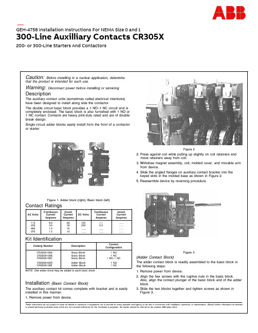
Caution: Before installing in a nuclear application, determinethat the product is intended for such use.Warning: Disconnect power before installing or servicing.DescriptionThe auxiliary contact units (sometimes called electrical interlocks)have been designed to install along side the contactor.The double circuit basic block provides a 1 N0-1 NC circuit and iscompletely enclosed. The basic block is also furnished with 1 NO or1 NC contact. Contacts are heavy pilot-duty rated and are of doublebreak design.Single circuit adder blocks easily install from the front of a contactoror starter.Figure 1. Adder block (ri g ht). Basic block (left)Contact RatingsContinuous Inrush Continuous InrushAC Volts Current Current DC Volts Current CurrentAmperes Amperes Amperes Amperes115 6.0 60 125 1.1 ......230 3.0 30 250 0.5 ......460 1.5 15 ......575 1.2 12 ......Kit IdentificationCatalog Number Description ContactConfigurationCR305X100A Basic Block 1 NOCR305X100B Basic Block 1 NCCR305X100C Basic Block 1 NO-1 NCCR305X100D Adder Block 1 NOCR305X100E Adder Block 1 NCNOTE: One adder block may be added to each basic block.Installation (Basic Contact Block)The auxiliary contact kit comes complete with bracket and is easilyinstalled in this manner:1.Remove power from device.Figure 2.2.Press against coil while pulling up slightly on coil retainers andmove retainers away from coil.3. Withdraw magnet assembly, coil, molded cover, and movable armfrom device.4.Slide the angled flanges on auxiliary contact bracket into thekeyed slots in the molded base as shown in Figure 2.5.Reassemble device by reversing procedure.Figure 3.(Adder Contact Block)The adder contact block is readily assembled to the basic block inthe following steps:1.Remove power from device.2.Align the hex screws with the captive nuts in the basic block.Also, align the contact plunger of the basic block and of the adderblock.3.Slide the two blocks together and tighten screws as shown inFigure 3.These instructions do not purport to cover all details or variations in equipment nor to provide for every possible contingency to be met in connection with install ation, operation, or maintenance, Should further information be desired or shoul d particular problems arise which are not covered sufficiently for the Purchaser's purposes, the matter shoul d be referred to the nearest ABB sales office.GEH-4758 Installation Instructions For NEMA Size 0 and 1300-Line Auxilliary Contacts CR305X200-or 300-Line Starters And Contactors-,7Figure 4Tables 1 and 2Location Of Additional Auxiliary ContactsNEMA Sizes O and 1, 300-Line three-pole, non-mechanical interlock!ld devices can handle up to four extra auxiliary contacts in any combination of normally open and normally closed circuits. The various contact configurations, the mounting locations of basic and adder blocks to make up these configurations, relative to the position of the contactor or starter, are shown in Table 1.LEFTr--,IwIt---1IX III y I L--...J BACKJ:. CD6RIGHT r--, ITIf---�I z III i y I I.. __ J BACKTable 1-Extra Auxiliary ContactTable 2-Kits For Field Modification-Order In Quantities Shown By Catalog NumberFinal SuffixContact LocationLetter Of Catalog Number wX yzTuA (Or None)B -II-C .'.:::f-D -II-�E -II--II-F ..::::+k .'.:::f-G -II--II-�H � -II-..:::::+ J -II--II--II-K .:::+k::.:::::+k �L -II--II--II--II-M �� .:::+k::� N-II-� -II-� p-II--II-� -II-R� -II-��CD Standard holding interlock.0 Both NO and NC contacts must be of same polarity.1 NO1 NC 1 NO-1 NC 1 NO 1 NC Adder Adder X100AX100BX100C 0X100DX100E11111111 11121 212222211111121S Q C 912014M 0201 G E H -4758C , N o v e m b e r 2020—ABB Inc.305 Gregson Drive Cary, NC 27511.—We reserve the right to make technical changes or modify the contents of this document without prior notice. With regard to purchase orders, the agreed particulars shall prevail. ABB Inc. does not accept any responsibility whatsoever for potential errors or possible lack of information in this document.We reserve all rights in this document and in the subject matter and illustrations contained therein. Any reproduction or utilization of its contents – in whole or in parts – is forbidden without prior written consent of ABB Inc. Copyright© 2020 ABB All rights reserved。
EN20-20N-01 安装接触器说明书
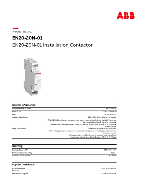
(230 V) Single Phase 4.6 kW
(230 V) Single Phase 1.3 kW
(NO) 20 A
(230 V) Single Phase 4.6 kW
(230 V) Single Phase, NO 9 A
(230 V) Single Phase 1.3 kW
Container Information
Package Level 1 Units Package Level 1 Width Package Level 1 Height Package Level 1 Depth / Length Package Level 1 Gross Weight Package Level 1 EAN
V11.0 : 27142308 39121529
4759 >> Installation contactor for distribution board 3707803
Categories
Low Voltage Products and Systems → Control Products → Contactors → Installation Contactors Low Voltage Products and Systems → Modular DIN Rail Products → Command and Signalling devices → Installation Contactors
Environmental
Ambient Air Temperature Maximum Operating Altitude Permissible Resistance to Shock acc. to IEC 60068-2-27 RoHS Status
定点接触器拆解与重装指南说明书

Replacing solenoid coil for 42.J31)Use the screw driver to unscrew the base plate & top cover of the contactor.2)Lift the base plate and magnet of the contactor assembly apart.3) Take out the solenoid coil from top cover.4)Place the shading ring onto the magnet properly.5) Insert the magnet into the new solenoid coil and place it on top cover. In doing so make sure that the magnet and solenoid coil of the contactor properly located on the support.6)Assemble the base plate and top cover of the contactor bytightening the screw with 1 N-m torque.DisposalSiemens product are environment friendly, which predominantly consist of recyclable materialsFor disposal we recommend disassembling and seperation into following materials:METALS: Segregate into Ferrous & Non Ferrous types for recycling through authorised dealer.PLASTICS: Segregate as per material type for recycling throughauthorised dealer. Because of the long lifetime of Siemens products the disposal guidelines may be replaced by other national regulations when taking the product out of service.The local customer care service is available at any time to answer disposal-related questions.Customer Care Toll free no. 1800 209 0987Email:ics.india@Order No. MISC4567_A Siemens Ltd.Product development is a continous process. Consequently the data indicated in this Leaflet is subject to change without prior notice.For latest issue contact our sales offices.Shading ringLast update: 18 March 2021。
德力西 OF3辅助触头 使用说明书

OF3Auxiliary ContactUser ManualStandard: GB/T 14048.5 Please carefully read this manual before the installation and operation of thisproduct, and keep it properly for future reference.Safety NoticePlease carefully read this manual before the installation, operation, run, maintenance, and inspection of the product, and install and operate this product properly according to the contents of the instructions.Danger:●It is prohibited to operate the auxiliary contact with your wet hands;●It is prohibited to touch the conductive part during operation;●Make sure that the product is de-electrified during the maintenance and service;●It is prohibited to use the short circuit method to test the product;Caution:●The installation, maintenance, and service shall be carried out by the qualified professionals;●The characteristics of the product have been set in factory, and the product cannot be installed, disassembled or adjusted without permission during operation;●Please confirm that the rated voltage, rated current, frequency, and characteristics of the product meet the working requirements before use;●In order to prevent short circuit between phases, the exposed wire or copper busbar on the wiring terminal shall be subject to the insulation treatment;●If found damage or abnormal sound when unpacking the product, please stop the operation immediately and contact the supplier;●This product is not suitable for some special occasions such as frequent startup of motor, electric heating equipment, capacitor cabinet, high conductive and high capacitive load, and high temperature environment.●When scrapping the product, please dispose the product waste properly; thanks for your cooperation.Table of Contents1 Main Purposes and Scope of Application. (1)2 Introduction on the Model and Its Meanings, and Panel of Product (1)3 Normal Operation, Installation, and Transport Conditions (2)3.1 Normal Operation and Installation Conditions (2)3.2 Normal Storage and Transport Conditions.. (2)4 Technical Features.. (2)4.1 Main Technical Performance Parameters (2)4.2 Other Technical Parameters (2)5 Outline and Installation Dimensions. (3)5.1 Outline and Installation Dimensions. (3)5.2 Wiring Diagram (3)6 Installation and Operation (Maintenance) (4)7 Unpacking Inspection. (5)8 Company’s Commitment.. (5)1 Main Purposes and Scope of ApplicationOF3 series auxiliary contact is primarily used in the AC 50/60Hz auxiliary circuit with a rated voltage of not greater than 415V and with a rated current 1A~6A. This series auxiliary contact can realize the remote display of the ON/OFF state of circuit breaker through the remotely connected signal lamp.2 Introduction on the Model and Its Meanings, and Panel of Product●Product mode and its meaningsDesign No.Miniature aux. contact series●Panel introductionLegends:1 Company logo2 Company name 3. Indication mark 4 Input terminal 5 Normally-closed outlet terminal 6 Normally-open outlet terminal 7 Technical terminal 8 Assembly diagram 9 Standard 10 Certification mark 11 Torque, wire stripping indication and wiring terminal indication 12 Knock off hole cover3 Normal Operation, Installation, and Transport Conditions3.1 Normal Operation and Installation Conditionsa) The upper limit of the ambient air temperature does not exceed +70℃, and the lower limit is not below -35℃, and the mean temperature within 24h does not exceed +35℃;b) The altitude at the installation site does not exceed 2000m;c) When the temperature is +40℃, the relative humidity of air does not exceed 50%; a larger relative humidity is allowed at lower temperatures; for example, the relative humidity does not exceed 90% at +20℃. Special protective measures are taken for condensations occurred occasionally due to temperature changes;d) The external magnetic field nearby the auxiliary contact installation site shall not exceed 5 times earth’s magnetic field in any direction;e) Installed in a place where there is the medium without any explosion danger and there is no gas or dust sufficient to cause corrosion to the metal and damage to the insulation layer in the medium;f) Installed in a place free from obvious impact vibration or rain and snow immersion;g) Pollution level: Level 2;h) Installation category: Class II, Class III;i) Installed in a power distribution tank, a power distribution cabinet or box;3.2Normal Storage and Transport Conditionsa)The lower limit of the temperature is not below -40℃, and the upper limit does not exceed +85℃;b)The relative humidity (at 25℃) does not exceed 95%;c)Please handle the product gently during the transport process, do not upside it down, and prevent severe impact as much as possible.4 Technical Features4.1 Main Technical Performance Parametersa) Contact use category: AC12, DC12;b) Rated operating current (Ie) under the different rated operating voltage (Ue) of the contact:AC: 415V/3A, 240V/6A, DC: 130V/1A, 48V/2A, 24V/6A.4.2 Other Technical Parametersa) Rated insulation voltage (Ui): 500V;b) Mechanical life: 6050 times;c) Rated impulse withstand voltage (Uimp): 4kV.5 Outline and Installation Dimensions5.1 Outline and Installation DimensionsThe outline and installation dimensions of the product are illustrated in Fig. 1.Fig 1 Outline and installation dimensions 5.2 Wiring DiagramThe product wiring diagram sees Fig. 2.Fig. 2 Wiring diagram6 Installation and Operation (Maintenance)●Before installing auxiliary contact:a)Check whether the technical parameters on the transfer printing mark meet the operation requirements;b)Before use, users are required to check that the insulation resistance between the poles of the auxiliary contact (except for single pole), between the pole and the housing, between the pole and the mounting rail, and between the input terminal and the output terminal with a 500V megger shall not be less than 5MΩ. If the insulation resistance is less than 5MΩ, stop the operation of this product, and contact the suppler for timely replacement;c)The auxiliary contact shall match with some models of miniature circuit breaker such as DZ47s, DZ47sLE, DZ47PLE, DZ47PLEi, DZ47v, DZ47vLE and DZ47vPLE to indicate the ON/OFF state of circuit breaker;d)The auxiliary contact is assembled on the left side of circuit breaker: The total width of the assembled accessory is within 54mm, and the sequence from left to right and the quantity are as follows: OF3/FF3/FS3/SD3 (3 max.) + MO3/MV3/MN3/MVMN3/MSN3/ MOWY3 (2 max.) + MCB;e)When assembling product at the left side of the auxiliary contact, please knock off the hole cover before assembly (see Item 12 on the Panel Introduction Diagram);f)Open and close the auxiliary contact several times, and check the auxiliary contact operating mechanism for blockage, and check whether the mechanism can work reliably;g)The reference temperature of this series auxiliary contact is +30+50o C. If multiple auxiliary contacts are all installed in a sealed tank, the tank temperature shall be correspondingly rise, and the operating current is 0.8In; h)The cross sectional area of the connected copper wire shall adapt to the rated current of the auxiliary contact; see Table 1;Table 1 Rated current, and cross sectional area of the connected copper wirei)This series auxiliary contact is of the rail-mounted type, suitable for TH35-7.5 steel mounting rail.●Maintenance and Service:a)The maintenance and service must be carried out by the qualified professionals;b)Ensure that the product is not de-energized;c)The product shall be maintained and service once annual under the normal operation conditions, and the maintenance contents are listed in Table 2.Table 2 Maintenance and Service7 Unpacking InspectionCheck the product for damage, check the exposed metal for rust, and check the product for any defect caused by poor transport or storge after unpacking the product. If found any of the above situations, stop the operation of the product and contact the supplier timely for this.8 Company’s CommitmentUnder the premise that users follow the use and storage conditions and the product are well sealed, within 36 months from the production date, our company will provide repair and replacement service free of charge for any damage or abnormal operation due to poor manufacture quality. A paid repair will be provided if the warranty period expires. For any damage due to one of the following situations, a paid repair will be given even if within the warranty period:a)Improper operation, maintenance, or storage;b)Modified and inappropriate repair without permission;c)Damage due to falling off or during installation after purchase;d)Force majeure such as earthquakes, fires, lightning strikes, abnormal voltages, and secondary disasters.If you have any question, please contact our dealer or our company’s customer service department. Customer service hotline:400-826-8008CertificateDELIXI ELECTRIC LTDName: Auxiliary ContactModel: OF3This product passes the section in the factory, and ispermitted to be shipped.Standard: GB/T 14048.5Inspector: Check 06Date of production: See label on inner boxAddress: Delixi High-Tech Industrial Park, Liushi Town, Yueqing City, ZhejiangP.C: 325604Tel: (86-577) 61778888Fax: (86-577) 61778000Service hotline: 400-826-8008The first version of this manual was issued in Oct. 2021。
交流接触器的安装方法 交流接触器如何操作

交流接触器的安装方法交流接触器如何操作1、检查铭牌与线圈的技术数据(如额定电压、电流、操作频率等)是否符合实际使用要求。
2、检查接触器外观应无机械损伤;用手推动接触器可动部分时,接触器应动作1、检查铭牌与线圈的技术数据(如额定电压、电流、操作频率等)是否符合实际使用要求。
2、检查接触器外观应无机械损伤;用手推动接触器可动部分时,接触器应动作快捷,无卡阻现象;灭弧罩应完整无损,固定坚固。
3、将铁心极面上的防锈油脂或粘在极面上的铁垢用煤油擦净,以免多次使用后衔铁被粘住,造成断电后不能释放。
4、测量接触器的线圈电阻和绝缘电阻,应符合要求。
5、一般应安装在垂直面上,倾斜度不得超过5°;若有散热孔,则应将有孔的一面放在垂直方向上,以利散热;并按规定留有适当的飞弧空间,以免飞弧烧坏相邻电器。
6、安装和接线时,注意不要将零件失落或掉入接触器内部。
安装孔的螺钉应装有弹簧垫圈和平垫圈,并拧紧螺钉以防振动松脱。
7、安装完毕,检查接线正确无误后,在主触头不带电的情况下操作几次,然后测量产品的动作值和释放值,所测数据应符合产品的规定要求。
—专业分析仪器服务平台,试验室仪器设备交易网,仪器行业专业网络宣扬媒体。
相关热词:等离子清洗机,反应釜,旋转蒸发仪,高精度温湿度计,露点仪,高效液相色谱仪价格,霉菌试验箱,跌落试验台,离子色谱仪价格,噪声计,高压灭菌器,集菌仪,接地电阻测试仪型号,柱温箱,旋涡混合仪,电热套,场强仪万能材料试验机价格,洗瓶机,匀浆机,耐候试验箱,熔融指数仪,透射电子显微镜。
交流接触器的安装方法1、检查铭牌与线圈的技术数据(如额定电压、电流、操作频率等)是否符合实际使用要求。
2、检查接触器外观应无机械损伤;用手推动接触器可动部分时,接触器应动作快捷,无卡阻现象;灭弧罩应完整无损,固定坚固。
3、将铁心极面上的防锈油脂或粘在极面上的铁垢用煤油擦净,以免多次使用后衔铁被粘住,造成断电后不能释放。
4、测量接触器的线圈电阻和绝缘电阻,应符合要求。
CJX1-6322辅助触头2A2B接触器

上海人民CJX1-63/22(3TB 3TF)系列交流接触器为交流50Hz 或60Hz,额定绝缘电压为660-1000V,在AC-3使用类别下,额定工作电压为380V时的额定工作电流为9-475A的交流接触器,它主要供远距离接通及分断电路之用,并适用与热继电器组成磁力起动器。
产品符合IEC60947-4-1、GB14048.4标准。
CJX1-63/22交流接触器为双断点直动式结构,具有三对常开触头,辅助触头最多为2常开、2常闭。
触头支持件与衔铁采用弹性锁扣联结,消除了薄弱环节。
在触头支持件或灭弧罩上设有试操作杆,便于手动操作和作为动作指示,Ie≤22A接触器无灭弧隔弧板,Ie≥32A为塑料灭弧罩并装有金属隔弧板。
触头材料采用具有高抗熔焊性及耐腐蚀的银合金。
接线螺钉采用新型自升起螺钉,瓦形垫与螺钉部分立刻节省接线工时。
全系列产品均可用螺钉安装,Ie≤32A的产品还可采用快速嵌入导轨紧固。
0577保2788顺2628CJX1-63/22工作条件:1、海拔高度不超过2000m2、周围环境温度:-25+55℃3、空气相对温度:在+40℃时不超过50%,在较低温度下允许有较大相对温度;4、大气条件:没有会引起爆炸危险的介质,也没有会腐蚀金属和破坏绝缘的气体和导电尘埃;5、在无显著摇动和冲击振动的地方;6、在没有雨雪侵袭的地方。
CJX1-63/22交流接触器①.节能:传统接触器的合闸保持是靠合闸线圈通电产生电磁力来克服分闸弹簧来实现的,一旦电流变小使产生的电磁力不足以克服弹簧的反作用力,接触器就不能保持合闸状态,所以,传统交流接触器的合闸保持是必须靠线圈持续不断的通电来维持的,这个电流从数十到数千毫安。
而永磁交流接触器合闸保持依靠的是永磁力,而不需要线圈通过电流产生电磁力来进行合闸保持,只有电子模块的0.8mA—1.5mA的工作电流,因而,能限度地节约电能,节电率高达99.8%以上。
②. 无噪音:传统交流接触器合闸保持是靠线圈通电使硅钢片产生电磁力,使动静硅钢片吸合,当电网电压不足或动静硅钢片表面不平整或有灰尘、异物等时,就会有噪音产生。
AF400-1250接触器中文操作说明

ABB Automation Products, Cewe-Control SE-721 61 Västerås, Sweden Telephone +46 21 32 07 00Telefax +46 21 12 60 01接触器使用手册Contactors Schütze Contacteurs Kontaktorer Contattori Contactores KontaktoriOperating instructionns Betriebsanlietung Notice d’instructions InstruktionIstruzioni tecnicheIlnstrucciones de empleo OhjeWarning! The operation, installation and servicing of this product must be carried out by a qualified electrician, following installation standards and safety regulations. Before operating the contactor, make sure that the control voltage supply corresponds with the coil marking. Wrong control voltage can damage the coil. Do not touch live parts. Danger!Warnung! Die inbetriebnahme und die installation des vorhandenen Gerätes sowie jegliche Wartungsarbeiten müssen durch einen Fachelektriker, der die anerkannten technischen Regeln, die Montagenormen und die Sicherheitsvorschriften beachtet, durchgefürt werden. Vor Inbetriebnahme der Schüttze prüfen ob Steuerspannung am Verwendungsort mit den aufgedruckten Spulendaten übereinstimmt. Der Anschluss einer anderen Steuerspannung kan zur Zerstörung der Spule führen. Spannung führende Teile nicht berühren. Lebensgefahr!Attention! La mise en ceuvre et I'installation de cet appareil et toute intervention doivent être affectuées par un électricien professionnel appliquant les normesd'installation et les réglements de sécurité. Avant la mise en marche des contacteurs, vérifier que la tension du circuit de contrôle correspond bien aux indications de la bobine. Le raccordement d'une tension différente peut mener à une destruction de la bobine. Ne pas toucher les pièces sous tension. Danger de mort!Varning! Igångsättning och installation av apparaten samt alla ingrepp bör utföras av en kompetent elektriker enligt alla gällande installationsnormer och säkerhetsregler. Kontrollera före installation av kontaktorn att aktuell manöverspänning överensstämmer med spolens märkdata. Felaktig manöverspänning kan skada spolen. Beröring av spänningsförande delar är förenat med livsfara.Attenzione! La messa in opera, I'installazione di questo apparecchio ed ogni tipo di intervento devono essere effettuati da un elettricista professionista il quale applichi le regole del mestiere, le norme di installazione ed i regolamenti di sicuezza. Prima della messa in servizio del contattore, verificare che la tensione di alimentazione del circuito di comando corrisponda esattamente a quella indicata sulla bobina. L'alimentazione con una tensione diversa, puo provocare il danneggiamento della bobina. Non toccare le parti attive. Pericolo di vita!¡Atención! La instalación y puesta en marcha de este aparato, así como cualquier intervención, deben realizarse por un electricista profesional que aplique las normas de instalaciones eléctricas y la reglamentación de seguridad. Antes de la puesta en servicio del contactor, comprobar si coincide la tensión de mando que va a aplicar con los datos impresos en la bobina. La conexión de otra tensión de mando puede destruir la bobina. Las partes bajo tensión no deben tocarse. ¡Peligro de muerte!Varoitus! Tämän laitteen käyttäminen, asennus ja huoltaminen vaatii ammattihenkilön. Seuraavia asennusmääräyksiä ja turvaohjeita tulee noudattaa. Ohjausjännitteen ja kontaktorin kelaan merkityn jännitteen yhteensopivuus tulee varmistaa enne käyttönottoa. Epäsopiva käyttöjännite saattaa vioittaa kelaa. Älä koske jänniteisiin osiin. Vaara!注意!所有对此产品的操作、安装及维护,均需由合格的电气工程师,在遵循安装标准及安全准则的条件下进行。
交流接触器组装步骤

交流接触器组装步骤
嘿,朋友们!今天咱就来讲讲交流接触器组装这档子事儿。
交流接触器啊,就好比是电路世界里的一个小管家,负责开关电路的重要任务呢!你可别小瞧了它,组装它可得有点小窍门。
咱先得把那些零件都准备好呀,就像厨师做菜得先把食材备齐一样。
螺丝啦、触头啦、线圈啦等等,一个都不能少。
然后呢,就开始动手组装啦。
把触头小心翼翼地安装到位,就像是给小管家配上了灵活的双手。
这触头可得安装得稳稳当当的,不然怎么能好好工作呢?接着就是把线圈装上去,这线圈就像是小管家的动力源泉,没有它可不行呢。
在组装的过程中,可得仔细点呀,别毛毛躁躁的。
你想想,要是没装好,那不就像是一个不称职的管家,会把电路搞得乱七八糟呀!所以啊,每一步都要认真对待。
安装螺丝的时候,也得注意力度哦,不能太紧也不能太松。
太紧了,怕把零件弄坏;太松了,又怕不牢固。
这就跟系鞋带似的,不能系得太紧勒脚,也不能系得太松会散开。
等把各个部分都组装好了,就像是给小管家穿上了一身整齐的制服,准备上岗啦!这时候你再看看,是不是感觉很有成就感呢?
组装交流接触器虽然不复杂,但也需要我们的耐心和细心呀。
就好像我们盖房子,一砖一瓦都得放好,才能盖出坚固漂亮的房子。
这交流接触器也是一样,每个零件都安装到位了,它才能在电路里好好工作,为我们服务呀!
所以说呀,朋友们,可别小看了这小小的交流接触器组装,这里面的学问可大着呢!咱们可得认真对待,让这个小管家在电路里好好发挥作用。
怎么样,是不是觉得挺有意思的呀?赶紧自己动手试试吧!。
接触器与侧挂式辅助触头的安装结构
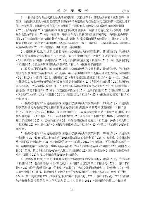
权利要求书1/2 页1 .一种接触器与侧挂式辅助触头的安装结构,其特征在于:辅助触头安装于接触器的一侧侧壁;所述辅助触头与接触器安装的侧壁的两端分别设有与接触器固定连接的第一连接组件和第二连接组件,辅助触头设有第一连接组件的一端设有与接触器安装拆卸配合的拆卸斜面( 23 ),拆卸斜面(23 )与接触器的侧壁之间形成辅助触头一端转动的避让空间;安装时,辅助触头设置拆卸斜面( 23 )的一端的第一连接组件先与接触器的侧壁安装固定,再绕设有拆卸斜面( 23 )一端的第一连接组件转动使第二连接组件与接触器的侧壁安装固定;拆卸时,先上拉辅助触头另一端的第二连接组件,绕设有拆卸斜面( 23 )一端的第一连接组件转动,辅助触头设置拆卸斜面( 23 )的一端倾斜,再拆卸第一连接组件。
2 .根据权利要求1所述的接触器与侧挂式辅助触头的安装结构,其特征在于:所述辅助触头与接触器的安装结构采用卡扣连接;第一连接组件和第二连接组件分别为固定卡扣组件( 21 )和弹性卡扣组件,拆卸斜面( 23 )设于接触器设置固定卡扣组件( 21 )一端,先安装固定卡扣组件( 21 )然后再转动辅助触头使弹性卡扣组件与接触器卡扣连接。
3.根据权利要求1所述的接触器与侧挂式辅助触头的安装结构,其特征在于:所述辅助触头与接触器的安装结构采用卡扣连接;第一连接组件和第二连接组件分别为固定卡扣组件( 21 )和活动卡扣组件( 22 ),拆卸斜面( 23 )设于接触器设置固定卡扣组件( 21 )一端,接触器与辅助触头安装侧壁的两端分别设有与固定卡扣组件( 21 )和活动卡扣组件( 22 )相应的安装卡扣结构,先安装固定卡扣组件( 21 )然后在转动辅助触头使活动卡扣组件( 22 )与接触器卡扣连接;活动卡扣组件( 22 )的一端连接有弹性元件( 3 ),活动卡扣组件( 22 )可压缩弹性元件( 3 )而产生位移,活动卡扣组件( 22 )位移使得活动卡扣组件( 22 )与接触器的安装卡扣结构卡扣连接。
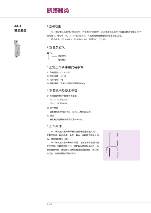
AX-1 辅助触头 说明书
4.2 介电性能辅助触头能承受2000V 1min的工频耐压试验。
4.3 寿命辅助触头的操作寿命不低于10000次。
,5 工作原理AX-1辅助触头是一种单断点三端子的通断触头元件,主要由手柄、脱扣机构、外壳、触头、接线端子等部分组成,其接线原理见右图。
AX-1辅助触头是一种附件产品,与断路器拼装后才能发挥作用。
当断路器断开时,辅助触头常闭触头闭合;当断路器合闸时,辅助触头随断路器进行通断转换,常开触头闭合,外接信号指示同时转换。
AX-1辅助触头1 适用范围AX 1设计序号 辅助触头- 2 型号及含义AX-1辅助触头主要用于交流50Hz,约定发热电流至3A,交流额定电压至415V或直流额定电压至125V 的线路中,可与CB-60、CB-125等产品拼装,作远距离断路器通断的信号指示之用。
符合标准:GB 14048.5、IEC 60947-5-1,获得CCC、CE认证。
3 正常工作条件和安装条件3.1 环境温度:-353.2 相对湿度:≤95%3.3 污染等级:2级3.4 海拔高度:安装地点海拔不超过2000m℃~70℃4 主要规格及技术参数4.1 不同额定电压下额定工作电流 AC-12:AC415V/3A; DC-12:DC125V/1A。
35277.56 产品的拼装及安装6.1 AX-1可与CB-60、CB-125断路器拼装(与同一个断路器拼装最多不能超过三个辅助触头),拼装示意图 如下6.2 辅助触头与断路器拼装后,一起安装在TH35-7.5型钢安装轨上。
7 外形及安装尺寸8 订货须知8.1 ,X-1辅助触头;,;产品型号和名称A 8.2 订货数量如50台8.3 订货举例:AX-1辅助触头,50台。
AF 1650 接触器主触头处理简要指导书

AF 1650 接触器主触头处理简要指导书注意:接触器上下级铜排690V电源必须断开。
雷雨天气,不得登塔作业。
1、工具准备:最好准备一套如下图的套装工具。
现场维修空间较小,拆卸触头需用加长杆内六角扳手;拆卸控制板需用如下排的梅花螺丝刀(即拆软起板子的那种,但可能是大一号)。
卡簧钳子一把。
2、拆卸步骤:1)先拆除辅助触头和线圈控制线。
2)拆除指示的4个梅花螺丝钉,取下面盖。
下图为柜内实景,空间狭小,注意。
3)蓝色箭头所指为动触头连杆,绿色为动触头支架。
可按下图方式取下连杆;若触头没有被卡得很死,建议用华容道游戏的方式取下连杆,比较容易。
即:取下卡簧,将连杆先上串,按下C相触头支架,再下串连杆,反复几下,即可取下。
4)拆去线圈控制线,再拆除红箭头所指4个及对称右边位置的4个,共8个梅花螺丝钉,其他的不需拆除。
轻轻地取下整个控制板和动触头。
5)拆去控制板后,检查,可能会有类似下图的偏离情况。
取下动触头,用手即可将触头复位。
6)检查动静触头磨损情况。
若触头未偏离,只要没有粘连情况,可不更换。
但恢复安装时,一定要对正磨损的花纹。
若触头偏离,磨损很小,不超过下图黄色圈内情况,只要复位即可。
若磨损较大,如下图红色圈内情况,动静触头均要更换。
下图为对正磨损花纹示意图:7)恢复安装。
更换触头后,按相对正磨损花纹,将动触头先放进槽内,再将控制板慢慢放置到位。
恢复8个螺丝钉。
安装连杆。
恢复卡簧。
注意:下图的线圈机械件一定要检查好,恢复到位。
恢复后,双手同时按下两组线圈,动触头应动作正常。
8)安装面盖,动作要轻,不可用蛮力。
对准位置,各处不得有受力情况。
- 1、下载文档前请自行甄别文档内容的完整性,平台不提供额外的编辑、内容补充、找答案等附加服务。
- 2、"仅部分预览"的文档,不可在线预览部分如存在完整性等问题,可反馈申请退款(可完整预览的文档不适用该条件!)。
- 3、如文档侵犯您的权益,请联系客服反馈,我们会尽快为您处理(人工客服工作时间:9:00-18:30)。
CCL5-0 辅助触点. CCL5-01代表 1NC辅助触点 辅助触点 适用接触器: AE95...110-30-00, AE95...110-30-11. 按照j 按照j→k→l→m→n步骤 安装。
7
接触器辅助触头安装手册 接触器辅助触头安装手册 触头
CDL5-01,CCL5-01辅助触点电气接线和尺寸:裝 辅助触点电气接线 b) CDL5-01,CCL5-01辅助触点电气接线和尺寸:裝
CAL5-11,CCL5-11,CAL5-11B辅助触点安装 一 CAL5-11,CCL5-11,CAL5-11B辅助触点安装
CAL5-11,CCL5-11,CAL5-11B ,CCL5-11,CAL5-11B适用接触器: a) CAL5-11,CCL5-11,CAL5-11B适用接触器:
CAL5-11 代表 1NO+1NC 辅助 触头。适用接触器: N... ,A9...300, AF45...750, NE... , AE9...110, UA16...110. 安装 接触器辅助触头安装手册 触头
CAL5-11,CCL5-11,CAL5-11B ,CCL5-11,CAL5-11B与接触器的可能组合: e) CAL5-11,CCL5-11,CAL5-11B与接触器的可能组合:
6
接触器辅助触头安装手册 接触器辅助触头安装手册 触头
CDL5-01,CCL5-01辅助触点安装 二 CDL5-01,CCL5-01辅助触点安装
CAL5-11,CCL5-11,CAL5-11B 辅助 CAL5-11,CCL5-11,CAL5-11B 触点拆卸: 按照j 按照j→k步骤拆卸。
4
接触器辅助触头安装手册 接触器辅助触头安装手册 触头
CAL5-11,CCL5-11,CAL5-11B辅助触点尺寸 ,CCL5-11,CAL5-11B辅助触点尺寸及接线端子: d) CAL5-11,CCL5-11,CAL5-11B辅助触点尺寸及接线端子:
9
请按照左图所示连接控 制线圈,切勿将A1,A2 错接到A3端子!
8
接触器辅助触头安装手册 接触器辅助触头安装手册 触头
注意:
必须由合格的技术人员根据相应技术规范安装标准和安全准则进行 安装调试。在接触器通电以前必须确认控制电压符合支架上所标的 线圈电压标准,否则会损坏线圈。请勿接触带电部分。危险!
2
接触器辅助触头安装手册 接触器辅助触头安装手册 触头
CAL5-11,CCL5-11,CAL5-11B ,CCL5-11,CAL5-11B辅助触点的安装: b) CAL5-11,CCL5-11,CAL5-11B辅助触点的安装:
上安装CAL5-11, 在 A(E)9...26,UA16...26,N(E)...上安装 上安装 , 上安装CCL5-11: 在 A(E)9...16,N(E)...上安装 上安装 : 将一字形连接件插入第二个连接孔,丢弃工字形连 接件,然后按照j→k→l→m→n步骤安装。
3
接触器辅助触头安装手册 接触器辅助触头安装手册 触头
上安装CAL5-11B: 在 A145...AF750上安装 上安装 : 将工字形连接件插入第二个连接孔,然后按照j→k →l→m→n步骤安装。
CAL5-11,CCL5-11,CAL5-11B ,CCL5-11,CAL5-11B辅助触点的拆卸: C) CAL5-11,CCL5-11,CAL5-11B辅助触点的拆卸:
接触器辅助触头安装手册 接触器辅助触头安装手册 触头
本安装手册适用范围: 接触器 A9...A300 A9...A300 AF45... 5...AF750 AF45...AF750 AE9...AE110 AE9...AE110 UA16...UA110 UA16...UA110 N... NE... 辅助触点 CAL5-11, CAL5-11, CCL5-11, CAL5-11B, CDL5-01, CCL5-01,
CDL5-01,CCL5-01辅助触点安装和拆卸: a) CDL5-01,CCL5-01辅助触点安装和拆卸:
CDL5-0 辅助触点. CDL5-01代表 1NC辅助触点 辅助触点 适用接触器: (T)AE50...75-30-00, (T)AE50...75-30-11, (T)AE45...75-40-00, AE45...75-22-00.
在 A/UA30...110,AE/AF45...110,AF580...750上安装 上安装 CAL5-11: : 将工字形连接件插入第一个连接孔,丢弃一字形连 接件,然后按照j→k→l→m→n步骤安装。
上安装CAL5-11: 在 A/AF145...300,AF400...460上安装 上安装 : 将工字形连接件插入第二个连接孔,丢弃一字形连 接件,然后按照j→k→l→m→n步骤安装。
1
接触器辅助触头安装手册 接触器辅助触头安装手册 触头
CCL5-11 代表 1NO+1NC 辅助 触头。适用接触器: N... ,A9...A16, NE... , AE9...AE16.安装在接触器左 安装在接触器左 侧或右侧第一片。
CAL5-11B 代表 1NO+1NC 辅助 触头。适用接触器: A145...AF750。 。 安装在接触器左侧或右侧第二片。
