AT009 1~17Key(可定制)电容式触摸感应IC_ 规格书_ V1.1
WTC6216BSI规格书V1_5

-50℃-+125℃
SSOP28(150MIL)
各种家用电器,安防设备,通讯设备,工业控制设备仪器仪表,,娱乐设备, 医疗设 备,体育设备,玩具等.
1
咨询电话:0755-26406919,13392806258 Email:cs@
8. WTC6216BSI 的电源....................................................................................................................................... 12 8.1. 直流稳压器 ................................................................................................................12 8.2. 稳压器组件的放置.....................................................................................................13 8.3. 接地 ............................................................................................................................13
SC09A触摸IC规格书v10
环境的漂移来调整基准值。 *按键反应时间
芯片可以检测到的按键频率大于10次/秒。
2011.07
SC09A Spec 1.0 4
额定值*
工作温度.................................. -40°C to +85°C 存储温度 ..................................... -50°C to +15 0°C 最大工作电压............................................. 6.5V 管脚的容限电压 .....................................VDD+0.3v 功率损耗 .....................................80mW 直流输出电流...................................................... 10.0 mA *注意: 超出上述额定值可能导致芯片工作不正常并且导致芯片的永久损坏。
封装
2011.07
SC09A Spec 1.0 2
I2C 接口定义
总线的构成及信号类型 I2C总线是由数据线SDA和串行时钟线SCL构成的串行总线,可发送和接收数据。在信息的传输过 程中,SC09A是被控器(slaver),主控MCU是主控器(master)。 SCL是串行时钟线,在通信过程中始终由主控MCU控制; SDA是数据线,接上拉电阻,主控器(master)和被控器(slaver)都可以控制SDA线,它们芯 片内部是open-drain结构(即输出高电平时为上拉电阻或高阻,输出低电平时是强驱动),发送 “0”时通过芯片内部的NMOS将SDA线拉低,发送“1”时释放总线由上拉电阻将SDA线拉到高电 平。在SCL的低电平时改变状态来发送地址、数据和ACK信号,在SCL的高电平时改变状态来发送 开始和结束信号。 开始信号(start):SCL 为高电平时,SDA 由高电平向低电平跳变,开始传送数据。 结束信号(end):SCL 为高电平时,SDA 由低电平向高电平跳变,结束传送数据。 应答信号(ACK):SC09A 在接收到读命令后,如果地址正确,会向主控制器发出低电平脉冲, 表示已收到数据。
8通道触摸感应IC_ADPT008 规格书 V9_6
流
Iop3
睡眠 空闲 低速 正常
-
1
3
uA 睡眠
-
4
6
uA 空闲
25
30
uA 低速
0.55
0.7
mA 正常
Vih1 最小输入高电压
-
2
-
V Vdd=5V
Vil1 最大输入低电压
-
1
-
V Vdd=5V
Voh1 最小输出高电压 4.5
-
-
V Vdd=5V, Ioh=4mA
Vol1 最大输出低电压
-
-
0.5
单位 V V V ℃ ℃ Hz
V
6. 电气特性
6.1 直流电气特性
(VDD-VSS = 3.0V, 无负载, 主时钟 = 4MHz, 子时钟 = 32768HZ 在晶振模式下. Ta = 25℃)
特征量
参数描述
最小值 典型值 最大值 单位
测试条件
VDD
工作电压
2.4
5.5
V
Isb
LC717A00ARGEVK 电容数字转换器IC电感触摸传感器评估板用户手册说明书
LC717A00ARGEVKLC717A00ARGEVK Capacitance‐Digital‐Converter IC for Electrostatic Capacitive Touch Sensors Evaluation Board User's ManualIntroductionThis manual contains configuration, usage, setup guide (page12), and main specifications regarding Capacitance touch sensor Evaluation board set (LC717A00ARGEVK). For the latest edition of this manual, please refer to ON Semiconductor homepage.Product OutlineThis set includes four (4) different Evaluation boards that can evaluate Capacitance touch sensor operation in various switch patterns and Communication tools to make register setting changes on PC.∙Capacitance Touch Sensor Evaluation Board “LC717A00AR01GEVB”∙Capacitance Touch Sensor Evaluation Board “LC717A00AR02GEVB”∙Capacitance Touch Sensor Evaluation Board “LC717A00AR03GEVB”∙Capacitance Touch Sensor Conversion Module “LC717A00ARGPGEVB”∙Multi-functional USB−I2C Conversion Module “MM−FT232H”∙USB CableEVALUATION BOARDS LC717A00AR01GEVB Evaluation BoardThis Evaluation board has 4⨯2 switch pattern with an LED on the center. Acrylic board is mounted on the board with a space of approx. 1.5mm. When the user touches the Green light, which is lit under this acrylic board, the color will change to Red.Configuration1.Connector for Multifunctional USB−I2CConversion module:This is used to connect Multifunctional USB−I2Cconversion module “MM−FT232H”. By using thismodule, user can connect the Evaluation board andPC. By connecting this Evaluation board to PCand activating Touch sensor evaluation application“LC717A00AR Software” on PC, user can changethe parameter of touch sensor LSI, or can monitoran operation condition. Also, power will besupplied from this connector.2.Power source switching jumper:This is used to set a supplier of the power source.If this is set on “PC” side, power is supplied fromMultifunctional USB conversion module. If this isset on “AC ADAPTER” side, power is supplied from DC jack.3.DC Jack:This is used to connect AC adopter (+5V). (Note: Using wrong polarity will damage this jack) 4.RESET switch:This is used to RESET Capacitance touch sensor LSI. Use this switch when Error LED is lit or if any abnormality is found during operation.5.Error LED:This will light up when error is occurring in Capacitance touch sensor LSI. When this LED is lit, press RESET switch to release the error.6.Capacitance touch sensor LSI:Please do not touch this during operation – It may cause malfunction or breakdown.7.Touch switch area:An area where Touch switch is located. Touch switch is Green at power ON. When the user touches the Green light, Touch sensor will reactand change the color to Red.EVAL BOARD USER’S MANUALFigure 1. Configuration of LC717A00AR01GEVBDC JackTouch Switch AreaPower Source Switching JumperConnector for MultifunctionalUSB Conversion ModuleRESET SwitchError LEDCapacitance Touch Sensor LSI (LC717A00AR)How to Use1.When receiving power from PC, set Power switching jumper to “PC” side and connect “MM −FT232H” to the connector forMultifunctional USB conversion module (See Figure 2). If receiving power from optional AC adapter, set the jumper to “AC ADAPTER” side and connect AD adapter to DC jack.2.Press RESET switch.3.Red LED will light up by touching Green LED light (See Figure 3).4.Press RESET switch in case of error LED light up or when Evaluation board is acting strange.5.Please note: If the user directly touches the IC on the Evaluation board or patterns with their finger,it may cause malfunction or breakdown.Figure 2. MM −FT232H ConnectionFigure 3. Red Turns On by Touching Green LightEvaluation Board LC717A00AR01GEVBMM −FT232HPin 7:UnconnectedPin 1:Connect this with VDD PinCAUTION:When supplying power from Multifunctional conversion module while having Power switch jumper on “AC ADAPTER” side, GreenLED will slightly light up. This is because the current flows via I 2C signal line and Pull-up resistor. PLEASE DO NOT USE IN THIS CONDITION – It may cause equipment failure.Also, please DO NOT supply power from both AD adapter and Multifunctional USB conversion module while having Power switch jumper on “AC ADAPTER” side – This may also cause equipment failure.LC717A00AR02GEVB Evaluation BoardThis Evaluation board has 8⨯1 switch pattern with an acrylic board placed on top of it. Touching the acrylic board will turn Red LED light on.Configuration1.Connector for Multifunctional USB −I 2C conversion module:A connector to connect “MM −FT232H”. By connecting this module, user can connect this Evaluation board with PC. By connecting this board to PC and activating Touch sensorEvaluation application “LC717A00AR software”on PC, user can change the parameter of touch sensor LSI, or can monitor an operation condition.Also, power will be supplied from this connector.2.RESET switch:This is used to RESET Capacitance touch sensor LSI. Press this when error LED is lit or any abnormality is found during operation.3.Error LED:This will light up when error is occurring inCapacitance touch sensor LSI. When this LED is lit, press RESET switch to release an error.4.Capacitance Touch sensor LSI:Please do not touch this during operation – It may cause malfunction or breakdown.5.Touch Switch Area:An area where Touch switch is located. Touch switch is Green at power ON. When the user touches the Green light, touch sensor will react and the color changes to Red.How to Use1.Connect “MM −FT232H” (See Figure 2).2.Press RESET switch.3.Red LED will light up by touching silk prints on the board.4.Press RESET switch if error LED is lit or when Evaluation board is operating strange.5.Please note: If the user directly touches the IC on the Evaluation board or patterns with their finger,it may cause malfunction or breakdown.Figure 4. Configuration of LC717A00AR02GEVBLEDTouch Switch AreaConnector for MM −FT232HRESET SwitchError LEDCapacitance Touch SensorLC717A00AR03GEVB Evaluation BoardThis Evaluation board has 4⨯2 switch pattern with an acrylic board placed on back side of the board. Red LED will light up by touching silk print area (SW1~SW8) of the Touch switch.Configuration1.Pin for Multi-functional USB conversion module:This is a pin to solder Pin header of2.54mm pitch and connect “MM −FT232H”. By connecting this module, parameter change of Touch sensor LSI and the operation condition can be monitored by using Touch sensor evaluation application “LC717A00AR Software” on B Connector:This is used for PC connection. This connector does power delivery only and PC does not identifythis connector as USB device. In case of using “LC717A00AR Software”, please use pins for “MM −FT232H”.3.Error LED:This will light up when error is occurring inCapacitance touch sensor LSI. When this LED is lit, unplug Evaluation board from PC and plug back again.4.Capacitance Touch sensor LSI:Please do not touch this during operation – It may cause malfunction or breakdown.5.Touch Switch Area, LED:An area where Touch switch is located. Red LED will light up by touching silk print area (SW1~SW8) of the Touch switch.How to Use1.Connect USB connector of the Evaluation board to USB connector of the PC.2.Red LED light will light up by touching silk print on the board.3.When error LED is on or having strangeEvaluation board operation, unplug the Evaluation board from PC, and plug back again.4.Please note: If the user directly touches the IC on the Evaluation board or patterns with their finger,it may cause malfunction or breakdown.Figure 5. Configuration of LC717A00AR03GEVBLEDTouch Switch AreaPin for MM −FT232HUSB ConnectorError LEDCapacitance Touch Sensor LC717A00ARGPGEVB Conversion ModuleThis is a sensor module with Capacitance touch sensor LSI “LC717A00AR” on DIP IC form of board that has 28pins with 600mil width. This is used to evaluate self-produced switch patterns.Figure 6. LC717A00ARGPGEVBReset SwitchCapacitance Touch SensorPower LEDPlease refer to Detail Description of LC717A00ARGPGEVB section for more detail.MM −FT232H Multifunctional USB −I 2C Conversion ModuleThis is a module for USB Interface and I 2C t Interface conversion. This is used when connecting each Evaluation board and PC. When connecting to the Evaluation board,please set I/O switching jumper on 5V side.Figure 7. Configuration of MM −FT232HI/O Power Switching JumperUSB ConnectorConnector for Evaluation Board ConnectionMAIN SPECIFICATIONSMain specifications of each device are as listed below:Table 1. MAIN SPECIFICATIONS OF LC717A00AR01GEVBParameter Conditions RamarksBoard Size155⨯115 (mm)Board Material Glass Epoxy (FR4)Copper Foil 35m m, Thickness 1.6mm, Double-sided Board Supply Voltage5V Provided from either DC Jack or MM−FT232H Capacitance Touch Sensor LC717A00ARExternal RESET Circuit With Manual REWSET SwitchSwitch Pattern4⨯2 ConfigurationConnector6Pins⨯1Row, DC JackTable 2. MAIN SPECIFICATIONS OF LC717A00AR02GEVBParameter Conditions RamarksBoard Size127⨯28.5 (mm)Board Material Glass Epoxy (FR4)Copper Foil 35m m, Thickness 1.6mm, Double-sided Board Supply Voltage5V Provided from MM−FT232HCapacitance Touch Sensor LC717A00ARExternal RESET Circuit With Manual REWSET SwitchSwitch Pattern8⨯1 ConfigurationConnector6Pins⨯1RowTable 3. MAIN SPECIFICATIONS OF LC717A00AR03GEVBParameter Conditions RamarksBoard Size29⨯69(mm)Board Material Glass Epoxy(FR4)Copper Foil 35m m, Thickness 1.6mm, Double-sided Board Supply Voltage5V Provided from USB ConnectorCapacitance Touch Sensor LC717A00ARExternal RESET Circuit N/ASwitch Pattern4⨯2 ConfigurationConnector USB A TypeTable 4. MAIN SPECIFICATIONS OF LC717A00ARGPGEVBParameter Conditions RamarksBoard Size17.78⨯35.56(mm)Board Material Glass Composite (CEM3)Copper Foil 35m m, Thickness 1.6mm, Double-sided Board Supply Voltage 2.6 to 5.5VCapacitance Touch Sensor LC717A00ARExternal RESET Circuit With Manual REWSET SwitchSwitch Pattern4⨯2 ConfigurationConnector Connector 600mil Width 28PinsDIP TypeCIRCUIT DIAGRAMSFigure 8. LC717A00AR01GEVB U n p o p u l a t e dFigure 9. LC717A00AR02GEVBU n p o p u l a t e dFigure 10. LC717A00AR03GEVBFigure 11. LC717A00ARGPGEVBDETAIL DESCRIPTION OF LC717A00ARGPGEVB ConfigurationTouch Sensor LSI (LC717A00AR)Power LEDRESET SwitchFigure 12. Configuration of LC717A00ARGPGEVBTable 5. SIGNAL PIN FUNCTIONSNo Name I/O Functions1Pout7Output Cin0 Evaluation Result Output2Pout6Output Cin1 Evaluation Result Output3Pout5Output Cin2 Evaluation Result Output4Pout4Output Cin3 Evaluation Result Output5Pout3Output Cin4 Evaluation Result Output6Pout2Output Cin5 Evaluation Result Output7Pout1Output Cin6 Evaluation Result Output8Pout0Output Cin7 Evaluation Result Output9ERROR Output ERROR State Output10Cref Input Reference Capacity Input Pin11Cdrv Output Output for Capacitive Sensor Drive12INTOUT Output Interruption Output13GAIN Input Pin for Gain Initial Value Selection (JP1 Initialization : H Level = ⨯14)14GND−GND (EARTH)15Vdd−Power Source16SCL/SCK Input Clock Input (I2C)/Clock Input (SPI) (2.2k W Pull-up)17SDA/SI I/O Data I/O (I2C)/Data Input (SPI) (2.2k W Pull-up)18SA/SO I/O Slave Address Selection (I2C)/Data Output (SPI) (JP2 Initialization : L Level) 19CS Input Interface Selection/Chip Select Inverting Input (SPI)20RESET Input External RESET Signal Inverting Input (2.2k W Pull-up, with Switch)21Cin0I/O Capacitive Sensor Input22Cin1I/O Capacitive Sensor Input23Cin2I/O Capacitive Sensor Input24Cin3I/O Capacitive Sensor Input25Cin4I/O Capacitive Sensor Input26Cin5I/O Capacitive Sensor Input27Cin6I/O Capacitive Sensor Input28Cin7I/O Capacitive Sensor Input*For evaluation result output of Pout0~7; Evaluation result (ON/OFF) after removing Capacitive sensor input’s chattering will come out. Capacitive sensor’s measurement will become readable by connecting I2C compatible bus or SPI.Table 6. JUMPER, PATTERN FOR ADDITIONAL PARTSPattern Parameter Set ContentsJP1Initial Gain Setting H Level (1-2 Short) = High-sensitivity (⨯14)*: Initial Setting: H LevelL Level (2-3 Short) = Low-sensitivity (⨯7)JP2Slave Address Selection (I2C)/Data Output (SPI)When Interface is Selected as I2C Compatible Bus by CS Pin;H Level (2-3 Short) = 0x16 (7Bits)L Level (1-2 Short) = 0x17 (7Bits)*: Initial Setting: L LevelC3Pattern for Cref CapacityAdjustmentImplement Capacitor of any Capacity as Needed (Size: 1608)PRECAUTION FOR USE1.For approach in the use of IC and the design rule of the sensor pattern that will become the switch: Please refer to the User’s manual and FAQ pages in ON Semiconductor homepage.2.Regarding ON/OFF output change in accordance with long press of the switch:This happens with “Auto OFF function”. As a fail-safe function, if LSI is initial setting, output will be OFF after holding the switch for 10 seconds. By using Switch ON CountLower/Higher Register in I2C t compatible bus or SPI connection, the time to set OFF will be adjustable.SETUP GUIDEThank you for purchasing our “LC717A00ARGEVK”,the Capacitance touch sensor Evaluation board.Necessary Operational EnvironmentFollowing operational environment is necessary in order to use “LC717A00AR Software”, the Touch sensor Evaluation board application.∙Correspondence OS: Windows ®XP (32bit),Windows ®7(32bit)∙Memory capacity: More than 16MB∙Hard disc capacity: Amount of space ³ more than 500kB (Application size). Need additional size (optional) for obtaining Log file.∙Interface: USB2.0Setup1.Download the “D2XX drivers” from the corporate home page of FTDI ().2.Decompress the zipped file.3.Connect the “MM −FT232H” and the PC with USB Cable.4.Install of “D2XX drivers” for “MM −FT232H”.Once the installation is done, disconnect “MM −FT232H” from PC.5.Connect the “MM −FT232H” and the Touch sensor Evaluation board (LC717A00AR01GEVB or LC717A00AR02GEVB). Next, connect the “MM −FT232H” and the PC with USB Cable.6.Download the LC717A00AR Software, from /en/touch-sensor/pdf/LC717A00_Software.zip, and store on your PC.7.Decompress the zipped file into the any directory.8.Run the LC717A00AR Software“LC717A00ARApp.exe” in the above directory.9.Please refer to the documents and tools at /en/touch-sensor/index.php.Connecting Multifunctional USB Conversion ModuleWhere appropriate, please connect Capacitance touch sensor Evaluation board and Multifunctional USB conversion module as shown in the Figure 2.When connecting Multifunctional USB conversion module, make sure to have USB cable unplugged. When unplugging Multifunctional USB conversion module,please unplug USB cable before the module.Use of AC AdapterPlease use 5V AC adapter when using LC717A00AR01GEVB without connecting to PC.NOTE:Please take extra care for polarity – Using wrong polarity maycause IC damage.Some AC adapter with large anti-ground noise may not be used.Usage Advisory∙When using AC adapter, please switch the jumper of LC717A00AR01GEVB to AC adapter side.∙If error is displayed when starting “LC717A00AR Software”, please check the following:♦Please make sure that Device driver is operating correctly:If “!” is shown at “USB Serial Port” in Windows’“Device manager”, Device driver is not operating correctly. In such a case, disconnect the device from PC and reconnect it again. If “!” still shows up on the screen after disconnecting so many times, please reinstall the Device driver.∙Additional documents, FAQ, and any updates regarding this set are posted on ON Semiconductor homepage.We recommend all users to check the homepage regularly.ON Semiconductor Touch sensor webpage:/en/touch-sensor/index.phpON Semiconductor and are registered trademarks of Semiconductor Components Industries, LLC (SCILLC). SCILLC owns the rights to a number of patents, trademarks,copyrights, trade secrets, and other intellectual property. A listing of SCILLC’s product/patent coverage may be accessed at /site/pdf/Patent −Marking.pdf. SCILLC reserves the right to make changes without further notice to any products herein. SCILLC makes no warranty, representation or guarantee regarding the suitability of its products for any particular purpose, nor does SCILLC assume any liability arising out of the application or use of any product or circuit, and specifically disclaims any and all liability, including without limitation special, consequential or incidental damages. “Typical” parameters which may be provided in SCILLC data sheets and/or specifications can and do vary in different applications and actual performance may vary over time. All operating parameters, including “Typicals” must be validated for each customer application by customer’s technical experts. SCILLC does not convey any license under its patent rights nor the rights of others. SCILLC products are not designed, intended, or authorized for use as components in systems intended for surgical implant into the body, or other applications intended to support or sustain life, or for any other application in which the failure of the SCILLC product could create a situation where personal injury or death may occur. Should Buyer purchase or use SCILLC products for any such unintended or unauthorized application, Buyer shall indemnify and hold SCILLC and its officers, employees, subsidiaries, affiliates, and distributors harmless against all claims, costs, damages, and expenses, and reasonable attorney fees arising out of, directly or indirectly,any claim of personal injury or death associated with such unintended or unauthorized use, even if such claim alleges that SCILLC was negligent regarding the design or manufacture of the part. SCILLC is an Equal Opportunity/Affirmative Action Employer. This literature is subject to all applicable copyright laws and is not for resale in any manner.PUBLICATION ORDERING INFORMATIONWindows is a registered trademark of Microsoft Corporation I 2C Bus is a trademark of Philips CorporationLC717A00ARGEVK。
1键电容式触摸开关介绍
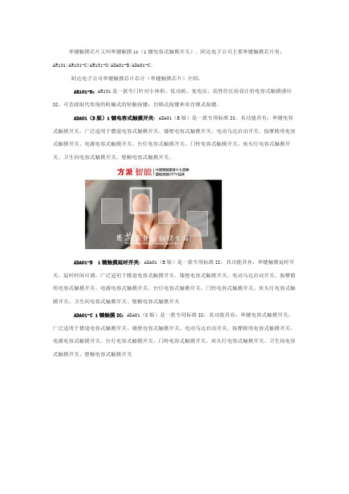
单键触摸芯片又叫单键触摸ic(1键电容式触摸开关)。
阿达电子公司主要单键触摸芯片有:AR101/AR101-C/AR101-D/ADA01-B/ADA01-C。
阿达电子公司单键触摸芯片芯片(单键触摸芯片)介绍:AR101-D:AR101是一款专门针对小体积、低功耗、宽电压、高性价比而设计的电容式触摸感应IC,可直接取代传统的机械式的轻触按键:自锁式按键和非自锁式按键。
ADA01(B版)1键电容式触摸开关:ADA01(B版)是一款专用标准IC,其功能具有:单键电容式触摸开关,广泛适用于楼道电容式触摸开关、墙壁电容式触摸开关、电动马达启动开关、按摩椅用电容式触摸开关、电源电容式触摸开关、台灯电容式触摸开关、门铃电容式触摸开关、床头灯电容式触摸开关、卫生间电容式触摸开关、壁橱电容式触摸开关。
ADA01-B1键触摸延时开关:ADA01(B版)是一款专用标准IC,其功能具有:单键触摸延时开关,延时时间可调,广泛适用于楼道电容式触摸开关、墙壁电容式触摸开关、电动马达启动开关、按摩椅用电容式触摸开关、电源电容式触摸开关、台灯电容式触摸开关、门铃电容式触摸开关、床头灯电容式触摸开关、卫生间电容式触摸开关、壁橱电容式触摸开关ADA01-C 1键触摸IC:ADA01(C版)是一款专用标准IC,其功能具有:单键电容式触摸开关,广泛适用于楼道电容式触摸开关、墙壁电容式触摸开关、电动马达启动开关、按摩椅用电容式触摸开关、电源电容式触摸开关、台灯电容式触摸开关、门铃电容式触摸开关、床头灯电容式触摸开关、卫生间电容式触摸开关、壁橱电容式触摸开关ADA01(C版)1键触摸延时开关:ADA01(C版)是一款专用标准IC,其功能具有:单键触摸延时开关,延时时间可调整,广泛适用于楼道电容式触摸开关、墙壁电容式触摸开关、电动马达启动开关、按摩椅用电容式触摸开关、电源电容式触摸开关、台灯电容式触摸开关、门铃电容式触摸开关、床头灯电容式触摸开关、卫生间电容式触摸开关、壁橱电容式触摸开关。
GOODIX GT9271 10点电容触摸控制器说明书
GT927110-Point Capacitive Touch Controller for MIDRev.04——Nov.11,2014======Disclaimer ======The information concerning the device in this publication is intended for you only and is subject to change without prior notice.It is your responsibility to ensure its application complies with technical specifications.Shenzhen Huiding Technology Co.,Ltd.(hereafter referred to as “GOODIX”)makes no representation or guarantee for this information,either expressed or implied,written or verbal,statutory or otherwise including but not limited to representation or guarantee for its application,quality,performance,merchantability or fitness for a particular purpose.GOODIX shall assume no responsibility for this information and relevant consequences arising out of the use of such information.Without written consent of GOODIX,it is prohibited to use GOODIX products as critical components in any life support system.This document conveys no licenses,implicitly or otherwise,to any intellectual property rights belonging to GOODIX.华信科专用Contents1.Overview ........................................................................................................................................................42.Features .........................................................................................................................................................43.Block Diagram .. (5)4.Pin Configurations (6)5.Sensor Design ..............................................................................................................................................75.1Layout of Rx Channels ....................................................................................................................75.2Layout of Tx Channels ....................................................................................................................75.3Sensor Design Specifications ........................................................................................................85.4Touch Key Design (8)6.I 2C Communication (9)6.1I 2C Timing (9)a)Data Transmission .....................................................................................................................11b)Writing Data to GT9271............................................................................................................11c)Reading Data from GT9271 (12)7.HotKnot (13)7.1Start HotKnot ..................................................................................................................................137.2Data Transmission between TPs ................................................................................................137.3Host Receives Data from GT9271 (13)8.Description on Functions (14)8.1Operating Modes ............................................................................................................................14a)Normal Mode ..............................................................................................................................14b)Green Mode ................................................................................................................................14c)Gesture Mode (15)华信科专用d)Sleep Mode .................................................................................................................................15e)Approach Mode ..........................................................................................................................15f)Receive Mode .............................................................................................................................16g)Send Mode ..................................................................................................................................168.2Interrupt Triggering Mechanism ...................................................................................................168.3Sleep Mode .....................................................................................................................................168.4Stationary Configuration ...............................................................................................................168.5Self-calibration ................................................................................................................................17a)Self-calibration during Initialization .........................................................................................17b)Automatic Drift Compensation (17)9.Sample Schematic (18)10.Electrical Characteristics ..................................................................................................................1910.1Absolute Maximum Ratings .........................................................................................................1910.2Recommended Operating Conditions ........................................................................................1910.3AC Electrical Characteristics ........................................................................................................1910.4DC Electrical Characteristics (20)11.Package ...............................................................................................................................................2112.Revision History .................................................................................................................................2213.Contact Information (23)华信科专用1.OverviewGT9271,a new-generation 10-point capacitive touch solution designed for 7”to 10.1”portable devices,consists of up to 32Transmitter electrodes and 20Receiver electrodes to provide higher accuracy and resolution.GT9271supports up to 10concurrent touches with real-time tracking of accurate position and motion trajectory as well as touch area.Furthermore,it is able to report such information to the host as required.2.Features✧Built-in capacitive sensing circuit and high-performance MPUReport rate:100HzOutputs touch coordinates in real timeUnified software applicable to capacitive touch screens of various sizes Single power supply,internal 1.8V LDOFlash embedded;In-system reprogrammableHotKnot integrated✧Capacitive touch sensorChannels:32(Tx channels)*20(Rx channels)Supports capacitive touch screen sizes:7”to 10.1"(diagonal) Supports touch key design on FPC Supports ITO glass and ITO FilmCover Lens thickness supported:0.7mm ≦Glass ≦2mm,0.5mm ≦Acrylic ≦1.2mm,Supports OGS full lamination ✧HotKnotTransmission rate :7.0Kbps(max)Data frame maximum capacity :128bytesApplicable sensor types:OGS/conventional,GFF/GG/GF✧Environmental adaptabilitySelf-calibration during initialization Automatic drift compensationOperating temperature:-40℃to +85℃;humidity:≦95%RHStorage temperature:-60℃to +125℃;humidity:≦95%RH✧Host interfaceStandard I 2C interface Works in slave mode华信科专用Supports 1.8V to 3.3V host interface voltage✧Response timeGreen mode:<48ms Sleep mode:<200ms Initialization:<200ms✧Power supply voltage:Single supply:2.8V to 3.3V✧Power supply ripple:Vpp ≦50mV✧Package:68pins,8mm*8mm QFN✧Tools provided to support application development:TP module parameter detector and generator Integrated tool for TP module performance testTool for quality inspection during module mass-productionReference driver code and documentary guide for host software development3.Block Diagram华信科专用4.Pin ConfigurationsPin Function description Remarks1~13SENS7~SENS19Receiver electrodesOutput drive signal while HotKnot function is on 14~17NC floating18AVDD28Analog power2.2uF filter capacitor to GND 19AVDD18 2.2uF filter capacitor to GND 20DVDD12 2.2uF filter capacitor to GND21DGND Digital signal ground 22INT Interrupt signal 23Sensor_OPT1Module ID pin 24Sensor_OPT2Module ID pin External pull-down resistorrequired25I2C_SDA I 2C data signal 26I2C_SCL I 2C clock signal 27VDDIO Supply voltage of GPIO2.2uF filter capacitor to GNDFloating:1.8VConnect to AVDD:AVDD 28/RSTB Reset pin External 10K pull-up resistor required,active-low reset 29~60DRV31~DRV0Transmitter electrodes 61AGNDAnalog signal ground 62~68SENS0~SENS6Receiver electrodesOutput drive signal while HotKnot function is on 华信科专用5.Sensor Design5.1Layout of Rx ChannelsSENS0to SENS19are 20Rx channels on the chip directly connected to 20ITO Rx channels on the sensor either in sequence or reverse sequence.Please refer to GT9Series Channel Selector for channel selection when there are less ITO Rx channels on the sensor than Rx channels on the chip.Sample Layout:the ITO Rx channels on the sensor are connected to the Rx channels on the chip in sequence from SENS0to SENS19:5.2Layout of Tx ChannelsDRV0to DRV31are 32Tx channels on the chip directly connected to 32ITO Tx channels on the sensor.Please refer to GT9Series Channel Selector for channel selection and assignment.After the layout of the Tx channels is determined,relevant registers of GT9271shall be configured to ensure logic positions of Tx channels are consistent with their physical positions,so that the reported coordinates match the physical coordinates.For details of sensor design,please refer to layout guidelines.华信科专用5.3Sensor Design SpecificationsGT9271DITO SITO Tx routing trace Impedance ≦3KΩ≦3KΩTx channel Impedance ≦10KΩ≦10KΩRx routing trace Impedance ≦10KΩ≦10KΩRx channel Impedance ≦40KΩ≦10KΩNode capacitance≦4pF≦4pFTo ensure data consistency and uniformity on the entire screen,it is necessary to ensure the sensor design complies with the above requirements.For detailed requirements,please refer to Sensor Design Guidelines of Goodix.In addition,when Tx channel/trace and Rx channel/trace are adjacent and parallel to each other,separate the traces with a ground trace.For ground trace width,please refer to Sensor Design Guidelines.Note that ground trace width should not be less than 0.2mm.5.4Touch Key DesignGT9271supports at most 4separated touch keys in the following two ways:1)Touch key design on sensor :Take one Tx channel as a common port for the touch keys andconnect the Tx channel to four Rx channels to enable four touch keys.The touch keys must not share their Tx channel with the touch screen.However,Rx channels have to be shared.2)Touch key design on FPC:Connect one separate Tx channel to four Rx channels to enablefour touch keys.The touch keys have to share their Rx channels with the touch screen.T ouch key pattern on FPC should be designed independently.华信科专用6.I 2C Communication6.1I 2C TimingGT9271provides a standard I2C interface for SCL and SDA to communicate with the host.GT9271always serves as slave device in the system with all communication being initialized by the host.It is strongly recommended that transmission rate be kept at or below 400Kbps.The I2C timing is shown below:Test condition 1:1.8V host interface voltage,400Kbps transmission rate,2K pull-up resistorParameterSymbol Min.Max.Unit SCL low periodt lo 1.3-us SCL high periodt hi 0.6-us SCL setup time for Start condition t st10.6-us SCL setup time for Stop condition t st30.6-us SCL hold time for Start condition t hd10.6-us SDA setup time t st20.1-us SDA hold timet hd2-usTest condition 2:3.3V host interface voltage,400Kbps transmission rate,2K pull-up resistorParameter Symbol Min.Max.Unit SCL low period t lo 1.3-us SCL high period t hi 0.6-us SCL setup time for Start condition t st10.6-us SCL setup time for Stop condition t st30.6-us SCL hold time for Start conditiont hd10.6-us SDA setup time t st20.1-us SDA hold timet hd2-UsGT9271supports two I 2C slave addresses:0xBA/0xBB and 0x28/0x29.The host can select the address by changing the status of Reset and INT pins during the power-on initialization phase.See the diagram below for detailed timings:华信科专用Power-on Timing:Timing for host resetting GT9271:Timing for setting slave address to 0x28/0x29:Timing for setting slave address to 0xBA/0xBB:华信科专用a)Data Transmission(For example :slave address is 0xBA/0xBB)Communication is always initiated by the host.Valid Start condition is signaled by pulling SDA line from high to low when SCL line is high.Data flow or address is transmitted after the Start condition.All slave devices connected to I 2C bus should detect the 8-bit address issued after Start condition and send the correct ACK.After receiving matching address,GT9271acknowledges by configuring SDA line as output port and pulling SDA line low during the ninth SCL cycle.When receiving unmatched address,namely,not 0XBA or 0XBB,GT9271will stay in an idle state.For data bytes on SDA,each of 9serial bits will be sent on nine SCL cycles.Each data byte consists of 8valid data bits and one ACK or NACK bit sent by the recipient.The data transmission is valid when SCL line is high.When communication is completed,the host will issue the Stop condition which implies the transition of SDA line from low to high when SCL line is high.b)Writing Data to GT9271(For example :slave address is 0xBA/0xBB)Timing for Write OperationThe diagram above displays the timing sequence of the host writing data onto GT9271.First,the host issues a Start condition.Then,the host sends 0XBA (address bits and R/W bit;R/W bit as 0indicates Write operation)to the slave device.After receiving ACK,the host sends the 16-bit register address (where writing starts)and the 8-bit data bytes (to be written onto the register).The location of the register address pointer will automatically add 1after every Write Operation.Therefore,when the host needs to perform Write Operations on a group of registers of continuous addresses,it is able to write continuously.The Write Operation is terminated when the host issues the Stop condition.华信科专用c)Reading Data from GT9271(For example :slave address is 0xBA/0xBB)Timing for Read OperationThe diagram above is the timing sequence of the host reading data from GT9271.First,the host issues a Start condition and sends 0XBA (address bits and R/W bit;R/W bit as 0indicates Write operation)to the slave device.After receiving ACK,the host sends the 16-bit register address (where reading starts)to the slave device.Then the host sets register addresses which need to be read.Also after receiving ACK,the host issues the Start condition once again and sends 0XBB (Read Operation).After receiving ACK,the host starts to read data.GT9271also supports continuous Read Operation and,by default,reads data continuously.Whenever receiving a byte of data,the host sends an ACK signal indicating successful reception.After receiving the last byte of data,the host sends a NACK signal followed by a STOP condition which terminates communication.华信科专用7.HotKnot7.1Start HotKnotWhen data needs to be sent,the host sends command 0x21to GT9271,enabling GT9271to enter "Master Approach mode"and work as a transmitting terminal.GT9271will then be able to detect the receiving terminal communicating with it.When GT9271succeeds in detecting the receiving terminal,it will notify the the host to shut off LCD using an interrupt signal and then transmit data to the receiveing terminal.7.2Data Transmission between TPsAfter GT9271and another Hotknot terminal successfully detect one another,the host sends the HotKnot transmission firmware to both terminals.While the transmission firmware runs,the two terminals are ready for data transmission,entering Receive mode by default.When the GT9271Transmit Buffer is flushed correctly,GT9271works as the transmitting terminal and immediately transmits data to the other HotKnot terminal,which works as a receiving terminal detecting data sent by GT9271.7.3Host Receives Data from GT9271Following recieval or transmission of a data frame,GT9271inverts INT to notify the host to process data.After receiving a data frame,the the host reads the value of the HotKnot-featured status register.If the value of the receive-status register indicates a successful reception,the host will read the data from the Receive Buffer via 12C.After reading the recieved data,the host writes 0xAA to the designated address and notifies GT9271that data reading is complete.After GT9271transmits a data frame,the host reads the value of the HotKnot-featured status register.If the value of the transmit-status register indicates a successful transmission,the host will read the data from the Transmit Buffer via 12C.After reading this data,the host writes 0xAA to the designated address and notifies GT9271that data reading is complete.GT9271will automatically switch to Receive mode and will not start transmitting until Transmit Buffer is flushed again.华信科专用8.Description on Functions8.1Operating Modesa)Normal ModeWhen GT9271is operating in Normal mode,its coordinate refresh period is subject to configuration (5ms to 20ms valid,one step is 1ms).When no touch is detected for a certain period (0s to 15s,subject to configuration;one step is 1s)in Normal mode,GT9271will automatically switch to Green mode to reduce power consumption.b)Green ModeIn Green mode,the scan period for GT9271is about 40ms.It automatically enters Normal mode if any touch is detected.华信科专用c)Gesture ModeAfter the host enables GT9271to enter Gesture mode by sending I 2C command 8to 0x8046and then to 0x8040.Wake-up can be achieved by swipe,double-tap,or writing of specified lower-case letters on Touch Panel (TP).In Gesture mode,when GT9271detects any finger swipe for a sufficiently long distance,double-tap or writing of specified letters on TP,INT will output a pulse for longer than 250us or output a high level.The host will wake up and turn on the screen after receiving such pulse and high level.d)Sleep ModeGT9271enters Sleep mode if it receives the corresponding I 2C command from the host (require INT output low before the command).GT9271exits Sleep mode and enters Normal mode when host outputs a high level to INT pin for 2ms to 5ms.The interval between sending screen-off command and wake-up should be longer than 58ms.e)Approach ModeWhen HotKnot proximity detection is enabled,GT9271enters Approach mode by default.If GT9271exits Approach mode,the host can send command 0x20or 0x21to enable GT9271to enter Approach mode again.In this mode,touch detection and HotKnot proximity detection alternate.If the host sends 0x21to GT9271,GT9271will work as a transmitting terminal and transmit signals with a specified pattern and frequency via Tx and Rx channels.Then,GT9271detects whether there are feedback signals with the same specified pattern and frequency from the receiving terminal.This helps to determine whether any receiving terminal exists.If the host sends 0x20to GT9271,GT9271will work as a Receiving terminal and detect signals with a specified pattern and frequency from the transmitting terminal.If such a signal is detected,GT9271responds using signals with the specified pattern and frequency to the transmitting terminal.In Approach mode,when detecting any HotKnot-compatible terminal within the near-field range,GT9271will notify the host via INT to capture status.To ensure reliable detection between the transmitting terminal and the receiving terminal,it is required to keep detecting for a minimum of 150ms after the two terminals have detected each other.Then the host sends HotKnot transmission firmware to enable GT9271to enter Receive mode.华信科专用f)Receive ModeIn Approach mode,after notified that GT9271has successfully detected another HotKnot terminal,the host sends HotKnot transmission firmware to enable GT9271to enter Receive mode.In Receive mode,GT9271continues to detect frame start signal,once the signal is detected,GT9271begins to detect and receive data.When the receiving process is complete,GT9271verifies the data.If GT9271finds erroneous data,the receiving process begins again.If the data is found to be correct,GT9271notifies the host via INT to read data in the Receive Buffer.g)Send ModeWhen GT9271works in Receive mode,the host sends outgoing data to the Transmit Buffer.When detecting that the Transmit Buffer is flushed and there is data to be sent,GT9271automatically switches from Receive mode to Send mode.In Send mode,GT9271sends a frame start signal.If it detects ACK fed back from the receiving terminal,it continues to send the data signal.After sending a data chunk,GT9271begins to detect ACK.If it does not detect any ACK or if it detects an erroneous ACK,GT9271will resend the data chunk.If this resending fails over 5times,it will resend the current data frame another time to the receiving terminal until the host enables GT9271to exit Send mode due to timeout.If GT9271detects ACK and sends the data successfully,it will automatically switch to Receive mode after the host completes the data processing or due to timeout.8.2Interrupt Triggering MechanismWhen touched,GT9271sends a pulse via INT pin in every scanning cycle to notify the host to read coordinates.Host will then set a triggering mechanism via relevant register “INT”bit.INT as “0”indicates rising edge-triggered,which means GT9271will notify the host by driving INT output from low to high when operated by user;INT as “1”indicates falling edge-triggered,which means GT9271will notify the host by driving INT output from high to low when operated by user .8.3Sleep ModeWhen the touch screen is off or there are no running operations on the TP ,the host sends I 2C command to enable GT9271to enter Sleep mode,which reduces power consumption.When GT9271needs to operate,the host outputs a high level to INT pin for a certain period to awake it.For detailed timings of host enabling GT9271to enter and exit Sleep mode,please refer to section 8.1.8.4Stationary ConfigurationGT9271supports Stationary Configuration.After receiving configuration parameters from the host,GT9271will fix parameters to the latest version.Once these parameters are fixed,GT9271will communicate with the host solely via I2C bus and will not receive any parameters of previous versions from the host.华信科专用8.5Self-calibrationa)Self-calibration during InitializationFluctuations in temperature,humidity and environment may affect the baseline of the capacitive sensor in idle state.GT9271will update detection baseline according to environmental conditions within the first 200ms of initialization.Then,GT9271will complete the initialization of the TP test.b)Automatic Drift CompensationGradual changes in environmental factors such as temperature,humidity,or dust may also affect the baseline of the capacitive sensor in idle state.GT9271will detect real-time changes in data and perform statistic analysis of historic data to revise the baseline and thus reduce the impact that environmental changes have on the TP test.华信科专用GOODIX CONFIDENTIAL9. S ample SchematicGT9271 sample schematicNote: ●This schematic only represents basic application. Adjustments may be required to fit in with actual situations and application environments.●It is recommended that the capacitor be ceramic X7R.Size Project NameRev Date:SheetofShenzhen Huiding Technology Co.,Ltd.GT92712.2Custom 11Tuesday , Nov ember 11, 2014The v oltage VDDIO sets the logic lev el. When VDDIO is connected to AVDD directly , the logic lev el is AVDD, otherwise, logic lev el is 1.8V.If there are pull-up resistors on the host I2Cbus, these two pull-up resistors on the module should be remov ed./RST /R S T AVDDTo enable "Gesture wake-up" f unction, this circuit should be connected to INT pin.DRV0DRV1DRV3DRV2DRV8DRV6DRV5DRV4DRV7DRV9DRV12DRV13DRV11DRV10DRV15DRV14DRV17DRV18DRV16DRV21DRV20DRV19DRV22DRV23DRV28DRV26DRV25DRV24DRV27A V D D 18AVDDD V D D 12S E N S 6S E N S 5SENS16SENS17SENS19SENS18SENS0SENS1SENS3SENS2SENS5SENS4SENS7SENS6SENS9SENS8SENS11SENS10Sensor ID connection methods f or COBSensor ID connection methods f or COFGND VDDIO GND S_OPT2NC NCGND NC VDDIO GND GND NC S_OPT2S_OPT1NC NC VDDIO GND GND GND SENS8300K 300K GND SENS12SENS9SENS10SENS_KEY3NC VDDIO 300K SENS14SENS11SENS13SENS_KEY4Module ID GND DRV_KEYSensor ID 1S_OPT1SENS15SENS_KEY2SENS_KEY1KEY11232KEY21245KEY31201Sensor IDKEY4124325Module3 Module2 Module1 Module5 Module4 Module1Module ID Module6 Module4 Module3 Module2 Module6 Module5O P T 1DRV29O P T 2SENS15SENS12SENS13SENS14D R V 31D R V 30J2DRV Interf ace12345678910111213141516171819202122232425262728293031323334U1GT9271A V D D 2818A V D D 1819D V D D 1220D G N D 21I N T 22S e n s o r _O P T 123S e n s o r _O P T 224I 2C _S D A 25I 2C _S C L 26V D D I O 27R S T B 28D R V 060D R V 159D R V 258D R V 357D R V 456D R V 555D R V 654D R V 753D R V 852DRV951DRV1050DRV1149DRV1248DRV1347DRV1446DRV1545DRV1644DRV1743DRV1842DRV1941DRV2040DRV2139DRV2238DRV2337DRV2436DRV2535D R V 2634D R V 2733D R V 2832D R V 2931E P69A G N D 61S E N S 062S E N S 163S E N S 264S E N S 365S E N S 466SENS71SENS82SENS93SENS104SENS115SENS126SENS137SENS148SENS159SENS1610SENS1711SENS1812SENS1913NC 14NC 15NC 16NC 17S E N S 567S E N S 668D R V 3030D R V 3129QFN8x8-68L-0.4PR210K VDDIODRV30DRV31A V D D 18AVDD C12.2uF C42.2uF V D D I OC32.2uF D V D D 12C510nFC22.2uF SENS16SENS17SENS18SENS19J3Host Interf ace123456OPT1Unused SENS or DRV Pins can be lef t f loating. For channel selection, please ref er to tool Channel Selector.D R V 0D R V 1D R V 3D R V 2D R V 5D R V 4D R V 6D R V 7DRV9D R V 8DRV10DRV11DRV12DRV25DRV20DRV23DRV22DRV24DRV16DRV18DRV19DRV21DRV13DRV14DRV15DRV17D R V 29D R V 27D R V 26D R V 28Interface sequence (for reference only)J4SENS Interf ace12345678910111213141516171819202122SENS7S E N S 4S E N S 3S E N S 1S E N S 0S E N S 2Sensor_OPT1 and Sensor_OPT2 are sensor ID pins. Six dif f erent kinds of connection method can distinguishamong 6 module manuf acturers. Sensor ID numbers 0-5 indicate 6 module manuf acturers respectiv ely. Sensor_OPT2 cannot be lef t f loating.ModuleMain boardS_OPT2213300kOPT2S_OPT2213R6300k OPT2VDDIOS_OPT1Key design rules:1.Support at most f our touch key s.Select a maximum of 4 sensing channels as SENS_KEY and select one separate driv ing channel as DRV_KEY.2.The sensing channels used by key s must be shared with the touch pannel.3. For DRV_KEY selection, please ref er to tool Channel Selector.AVDDJUMP1213VDDIOR52kR42kC61nF/RSTI2C_SCL I2C_SDA INT_A R7680INTINT_A I N T I 2C _S C L I 2C _S D A V D D I O 华信科专用10.Electrical Characteristics10.1Absolute Maximum Ratings(Ambient temperature:25℃)ParameterMin.Max.UnitAnalog power AVDD28(please referto AGND)2.663.47V VDDIO (please refer to DGND) 1.7 3.47V Voltage acceptable to digital I/O -0.3 3.47V Voltage acceptable to analog I/O -0.3 3.47V Range of operating temperature -4085℃Range of storage temperature -60125℃Welding temperature (10s)300℃ESD protection voltage (HB Model)-±2KV10.2Recommended Operating ConditionsParameter Min.Typ.Max.Unit AVDD28 2.8- 3.3V VDDIO1.8- 3.3V Operating temperature-202585℃10.3AC Electrical Characteristics(Ambient temperature:25℃,AVDD=2.8V,VDDIO=1.8V)ParameterMin.Typ.Max.Unit OSC oscillation frequency596061MHz I/O output rise time,low to high -14ns I/O output fall time,high to low-14ns华信科专用。
16位按键电容式感应触摸芯片HA3516中文版
HA3516_4R0.00_0906 Copyright © 2008 GOODIX CO., Ltd
抗干扰处理及独特技术
家电产品在使用应用中,通常会遭遇以下几类主要干扰源的干扰:
– 潮湿:天气和空气环境造成的潮湿引起的面板上的水平或潮气 – 溢水:由于各种原因导致的面板上溢水且各个按键上溢水的情况不一致 – 无线电干扰:由于手机、无绳电话、电视发射塔等无线电设备的使用造成的电磁辐射 – 电磁耦合干扰:家电产品内部的其他电磁部件工作而耦合或外部辐射源接触耦合而产生的
内容描述第一byte第二byte备注命令返回数据0x11读键值命令01000000无按键01010000按键101010001按键201010010按键301010011按键401010100按键501010101按键601010110按键701010111按键801011000按键901011001按键1001011010按键1101011011按键1201011100按键1301011101按键140101键值读到校验正确的键值之后确认为某个松开其他备用备注
1
HA3516_4R0.00_0906 Copyright © 2008 GOODIX CO., Ltd
一、 概述
基本工作原理
HA3516 采用矩阵扫描方式实现更多触摸按键的解决方案采用定时充放电差值法,利用固定时间对转 换模块电路进行充放电,根据后端电平变化差值,获取有/无按键的状态。
固定频率和占空比的信号 PWM 通过电容耦合进入转换电路,经二极管反向续流后会形成带直流分 量的脉动信号,简单滤波后输入到芯片内部进行检测。 当无按键时,该脉动直流电平是由稳定的电容的充放电、续流和滤波电路保持稳定。当有按键时候, 放电续流部分不会被改变,但充电部分受到手指加入的影响,相当于充电回路 RC 增大,在相同的 时间内,得到电压会比没有手指时候低。所以,在手指接触感应电极的时候,该点的直流电位下降 了。通过该直流电位的变化情况,分析是否有手指按键。 同一按键检测口上在外围硬件上连接了两个不同的感应按键,当 PWM1 和 PWM2(Pulse drive)快 速地分时切换,分别对两组按键进行检测。通过上述方式实现了 2x8 的矩阵扫描。 当手(人体)非常靠近或接触按键感应焊盘(或弹簧)时候,由按键检测电路提供给芯片的电压会 发生改变,体现为该电压下降。具体过程如下图所示(以下数据是在 5v VDD 供电,5mm 玻璃覆盖 厚度情况下测得):
APT7L05电容式触摸传感器数据手册说明书

APT7L05电容式触摸传感器数据手册1概述1.1APT7L05电容触摸传感器简述APT7L05是一款5通道多用途的电容触摸传感器,适合任何形式的触摸按键控制。
APT7L05采用直通形式,可以方便快捷地取替传统机械按键。
1.2特征◆电容触摸按键:5通道(每一通道独立工作);◆抗干扰能力强:可抵抗5W大功率对讲机测试,有效防止水滴;◆灵敏度:适合面板厚度在5mm以内的应用。
灵敏度调节详见参考电路(本手册第10页);◆输出模式:直通模式或锁存翻转模式可选(详见OM端口说明);◆上电后默认输出电平高低可选(详见OL端口说明);◆低功耗:工作电流为45uA@5V◆内置LDO:提高抗噪性能,并减少系统成本;◆工作温度:–40︒C到+85︒C;◆工作电压:2.2V到5.5V;◆封装及型号:QFN16(APT7L05NF)、SOP16(APT7L05SF)、SSOP16(APT7L05VF)。
1.3管脚分配图1-3-2APT7L05管脚分配(SOP16/SSOP16)图1-3-1APT7L05管脚分配(QFN16)1.4管脚功能说明表1-4APT7L05管脚说明管脚名称说明QFN16管脚位SOP16/ SSOP16管脚位C0外部电容:10nF(103)13K<4:0>触摸按键输入(不使用时必须悬空)2-64-8 O<4:0>对应触摸按键K<4:0>的输出7-119-13SS全局灵敏度输入控制脚,默认上拉;当接地时,灵敏度提高。
1214OL 接地时,O<4:0>默认输出高电平,当K<4:0>按下时输出低电平;悬空或接VDD时,O<4:0>默认输出低电平,当K<4:0>按下时输出高电平;1315OM 接地时为锁存翻转模式:当K<4:0>按下时,对应O<4:0>输出电平改变并保持(即使松开按键),当下一次按下时,对应O<4:0>输出电平翻转并保持(即使松开按键);悬空接VDD时为直通模式:当K<4:0>按下时,对应O<4:0>输出电平改变,松开K<4:0>时,对应O<4:0>输出电平恢复默认状态;162V DD芯片电源脚1416 V SS芯片地1512电气特性2.1极限参数表2-1极限参数(TA=25︒C)参数标号对象范围单位电源供电电压VDD––0.3to+6.5V端口输入电压VI所有端口–0.3to VDD+0.3V端口输出电压VO所有端口–0.3to VDD+0.3V高电平输出电流IOH单个口–10mA所有口–40mA低电平输出电流IOL单个口+20(峰值)mA所有口+60(峰值)mA工作温度TA––40to+85°C储藏温度TSTG––65to+150°C 2.2直流电气特性表2-2直流电器特性(TA=–40︒C~85︒C,VDD=2.2V~5.5V)参数标号条件最小典型最大单位工作电压VDD-- 2.2 5.5V 输出高电平VOH IOH=–10mA VDD=2.2to5.5V VDD-1.0-VDD V 输出低电平VOL IOL=20mA VDD=2.2to5.5V–- 1.0V输出高电平漏电流ILOH-VOUT=VDD––1uA输出低电平漏电流ILOL-VOUT=0V–––1uA供电电流IDD1工作模式VDD=2.2to5.5V–4560uA2.3交流电气特性表2-3交流电气特性(TA=–40︒C~85︒C,VDD=2.2V~5.5V)参数符号条件最小值典型值最大值单位输入电容CIN f=1MHz;不测试的管脚接地10pF输出电容COUT I/O口电容CIO3封装尺寸APT7L05采用QFN16,SOP16及SSOP16封装。
JL223B 单键电容式触摸按键IC_V1.2(3)

J L223B_SPECJL223B规格说明书版本 1.2 2014-03-08单键触摸开关本公司保留对规格书中产品在可靠性、功能和设计方面的改进作进一步说明的权利。
然而对于规格内容的使用不负责任。
文中提到的应用其目的仅仅是用来做说明,不保证和不表示这些应用没有更深入的修改就能适用,也不推荐它的产品使用在会由于故障或其它原因可能会对人身造成危害的地方。
该产品不授权适用于救生、维生器件或系统中作为关键器件,本公司拥有不事先通知而修改产品的权利。
1.概述JL223B是单键电容式触摸按键专用检测传感器IC。
采用最新一代电荷检测技术,利用操作者的手指与触摸按键焊盘之间产生电荷电平来确定手指接近或者触摸到感应表面。
没有任何机械部件,不会磨损,感测部分可以放置到任何绝缘层(通常为玻璃或者塑料材料)的后面,很容易制成与周围环境相密封的键盘。
面板图案随意设计,按键大小、形状自由选择,字符、商标、透视窗等可任意搭配,外形美观、时尚,而且不褪色、不变形、经久耐用。
从根本上改变了各种金属面板以及机械面板无法达到的效果。
其可靠性和美观设计随心所欲,可以直接取代现有普通面板(金属键盘、薄膜键盘、导电胶键盘)。
不需要对现有的程序做任何改动。
具有外围元件少、成本低、功耗少等优势。
2.特点l工作电压:2.0V-5.5V;l工作电流极低:3.5uA;l灵敏度可通过外部电容值来调整;l可实现同步输出模式及电平切换模式输出;l带有自校准的独立触摸按键控制;l高抗干扰性:内置稳压电路,环境自适应算法等多种措施;l带6秒自校准功能;l SOT23-6封装3.应用场合智能锁、智能手环、无线蓝牙耳机、移动电源、LED灯、玩具、MP4、触摸空气清新器、触摸音箱、触摸台灯、触摸指纹识别打火机等。
4.封装及引脚定义6.应用电路注1:C1电容值越大,灵敏度越低,感应面板的厚度就越薄。
反之电容值越小,灵敏度就越高,感应面板厚度就越厚。
芯片So 输入脚之间串接一个Rs 电阻,阻值在100-1000Ω之间。
RH6617_新版原厂规格书_Ver0.5
T.E.L:135.3045.2646单路输入双路输出触控型LED调光ICRH6617规格书Revision 0.5 2018-11-8目录1. 简介 (3)2. 特点 (3)3. 封装引脚示意图 (3)4. 功能描述 (4)4.1版本简述及模式配置 (4)4.2 输出模式 (4)4.1.1短按/长按 (4)4.1.2亮度记忆 (4)4.1.3渐明渐暗/突明突暗 (4)4.1.43级调光亮度 (5)4.1.5双输出模式控制流程 (5)5. 应用电路图 (5)6. PCB设计注意事项 (6)7. 电气参数 (6)7.1最大绝对额定值 (6)7.2DC/AC特性 (6)8. 封装信息 (8)8.1SOP8 (8)8.2DIP8 (9)1.简介RH6617是一款单路输入双路输出电容式触摸感应PWM调光IC。
RH6617可在有介质(如玻璃、亚克力、塑料、陶瓷等)隔离保护的情况下实现触摸功能,安全性高。
RH6617内置稳压源、上电复位/低压复位及环境自适应算法等多种措施,抗干扰性能优秀。
RH6617应用范围:触摸调光LED台灯、触摸调光LED壁灯或其他需要PWM 输出控制的触摸式产品。
2.特点工作电压:2.4V~5.5V待机平均电流:15uA@3V上电0.5s快速初始化环境自适应功能,可快速应对先上电后覆盖介质、触摸上电等类似应用场景可靠的上电复位(POR)及低压复位(LVR)性能 PWM输出频率24KHz(无级)、32KHz(三级调光),有效改善频闪封装形式:SOP8、DIP83.封装引脚示意图图1 SOP8/DIP8引脚示意图I-P H:带上拉电阻的CMOS输入I:CMOS输入O:推挽型CMOS输出I/O:CMOS输入/输出P:电源/地4.功能描述4.1版本简述及模式配置表2 版本型号列表型号无级调光初始亮度3级调光RH6617 100%,上电后第一次触摸开机亮度OFF/MAX/MID/MIN/OFF循环(1)注:1指配置为电源电压(VDD),0配置为0V电压。
ADA05 5Key(5键)电容式触摸感应专用IC_规格书_V1.3

1. 概述
ADA05 是一款有 5 个独立的电容式触摸感应通道和 5 个独立输出端口的触摸感应的专用集成电路。 本产品的特点和优势: 灵敏度可根据需要设置,选择范围宽,操作简单,使用方便 可在有介质(如玻璃、亚克力、塑料、陶瓷等)隔离保护的情况下实现触摸功能,安全性高 可直接触摸金属部件(如金属台灯,金属长臂灯等) 应用电路简单,外围器件少,加工方便,成本低。 抗电源干扰及手机干扰特性好。EFT 可以达到 4KV 以上;近距离、多角度手机干扰、对讲机干扰,触
J1
VCC
GND OUT1 OUT2 OUT3
OUT4 OUT5
1 2 3 4 5 6 7
图一: 5 个 key ,5 条输出线
1
1
1
1
VCC 1
U2 稳压IC
Vin
Vout
GND
+ C5 10uF
VDD 3
C6 1uF
2
OUT5
R5* R4* R3* R2* R1*
1 2 3 20K4 2200KK56 20K7 20K8
较小的电容特性相对比较稳定的高精度电容)
介质类型
VCI 与 GND 之间的采样电容
器件类型
器件参数
直接触摸金属外壳 102~104(缺省为 333)
0.001~0.1uF/25V(缺省为 33nf)
3mm 以内亚克力玻璃 102~103(缺省为 103)
0.001~0.01uF/25V(缺省为 10nf)
用法
输出 触摸输入 I I POWER POWER I
4. 封装 (SOP16)
功能描述
触摸按键对应的输出端口 触摸按键对应的输入端口 电压参考端 外部复位输入端 电源正极 电源负极 灵敏度电容输入端
电容式感应触摸芯片功能说明

触控焊盘自身存在一个分布电容。当手指或者其它物体接近触控焊盘时,触 控焊盘周围的环境(地)改变,导致其分布电容发生变化。这种变化由触控芯片 内部的专用电路转换成频率信号后,交给芯片内部软件处理,而后作出相应的控 制动作。
3、特征
1> 最多支持 8 通道触摸按键 2> 输出可选择为 IIC 或者一对一接口(1 脚选择) 3> 一对一接口下灵敏度端口电容细调,外部电阻 6 级粗调 , IIC 下内部寄存器设置, 4> 端口内部集成电阻,可省略串入电阻 5> 单多按键模式,长短按时间内部寄存器可设置 6> 上电 0.5S 快速初始化 7> 可过电流注入 10V、电子群脉冲 4KV、静电 15KV(非接触)测试 8> 防尘、防水、环境改变自动校准
7 IIC 通信
7.1 开始与停止
7.2 从机地址
7.3 写数据
7.4 读数据
7.5 数据传输注意事项 1,发送数据必须一次全部写入共 17 字节数据。16 字节(0xD0~0xDF)+1 字节校验和,单字节写入和校验码错误写入数据都会被丢弃; 2,传输速率<100K; 3,SDA/SCL 线均需要设置为开漏接口,输出高为外部电阻上拉产生。 输出低,芯片直接拉低。 4,从机(YS8XX)忙碌时 SCL 为低电平,此期间主机不可传输数据。 主机传输数据前,检查 SCL 为高,才能传输下一个数据。
读
按键数量
1-24Key
读
EEPROM 状态 Bit7=1 资料错误 Bit2=1 忙碌
保留
读
按键输出
Bit7 Bit6 Bit5 Bit4 Bit3 Bit2 Bit1 Bit0
08H K8 K7 K6 K5 K4 K3 K2 K1
触摸芯片SC09A规格书
SC09A 规格书 v2.0 9/11
附录:
通过I2C接口读取SC09A的C语言演示程序
// 使用 AT89S52 单片机
#define SDA
P1_5
#define SCL
P1_4
#define ERR
P1_3 // 指示通信过程有问题
#define CON_ADDR 0x81 // {A[6:0] + RWB} = 81H
2. 数据有效 在 SCL 为高电平期间,SDA 必须保持稳定的电平。SDA 线上的高低电平变化只能在 SCL 为低电平期
间。
SC09A 规格书 v2.0 6/11
3. 字节格式 字节由 8 位或 16 位数据和一个应答信号组成
4. SC09A 使用简化的 I2C 协议 1) 标准 I2C 器件有器件地址和寄存器地址。SC09A 只有器件地址。 2) SC09A 只接收读命令。 3) SC09A 的器件地址是 40H( A[6:0]=1000000B )。下图是一次完整的通信过程。D15~D13 和 D3~D0 是固定高电平,D12~D4 分别对应 CIN0~CIN8 是否有按键触摸。 例如,按键 CIN0 被触摸,D12 将是低电平,如果 CIN0 没有被触摸,D12 将是高电平。
I2C 接口
VDD
10K RU1
10K RU2
SC09A
SOP16
SDA SCL INT
VDD
10K RU1
SDA SCL
SC09A
SOP16
I2C
I2C
1. Start 和 Stop 信号 Start 信号(S) 当 SCL 是高电平时,SDA 由高到底变化,表示开始传输数据。 Stop 信号(P) 当 SCL 是高电平时,SDA 由低到高变化,表示结束数据传输。
奥普尚科技 ASC8022K ASC8022S 电容式触摸控制 ASIC 芯片说明书
销售部2:TEL:130****8198,QQ:2881651176 投诉与建议:134****1600数据手册DATASHEETASC8022K(同步模式直接输出) ASC8022S(保持模式锁存输出) 2键触摸感应开关芯片IC(Rev:1.4)销售部2:TEL:130****8198,QQ:2881651176投诉与建议:134****1600一、产品概述ASC8022K、ASC8022S是为实现人体触摸界面而设计的一款电容式触摸控制ASIC芯片,可替代机械式轻触按键,实现防水防尘、密封隔离、坚固美观的操作界面。
支持2通道触摸输入和输出,具有低功耗、高抗干扰、宽工作电压范围、高穿透力的突出优势。
二、主要特性1、工作电压范围:2.4~5.5V。
2、待机功耗低, 待机电流:9uA@VDD=5V & CMOD=10nF;6.5uA@VDD=3V & CMOD=10nF。
3、按键响应时间:小于100ms。
4、上电0.5秒快速初始化。
环境自适应功能,可快速应对先上电后覆盖介质、触摸上电等应用场景。
5、HBM ESD:±5KV以上。
6、按键持续长按最长时间:16秒(±30%)7、采用电荷分享方式实现触摸,独立2通道触摸按键输入输出。
8、有效电平选择(AHLB):可引脚配置高电平输出有效或低电平输出有效9、内置高精度LDO稳压源电路单元模块、上电复位(POR)、低压复位(LVR)、硬件去抖。
10、内置实时环境自适应算法,可随环境温度变化、触摸介质的环境变量调整参考值,确保按键判断正常工作。
11、内置高效数字滤波算法措施,抗电源纹波能力强,对电源纹波的干扰有很好的耐受能力,可抵抗<0.5V的电源纹波。
可靠性高,不影响芯片正常工作,有效防止由外部噪声干扰导致的误动作。
12、抗大功率RF发射设备、对讲机干扰能力强,近距离、多角度干扰情况下触摸响应灵敏度及可靠性不受影响。
13、高灵敏度,用户可自行调节, CMOD脚的外接电容Cm为灵敏度调节电容,电容越大灵敏度越高。
JL1821S触摸芯片IC规格书(5键输出自锁)_V11

数据手册DATASHEETJL1821S5键(输出自锁)触摸感应芯片IC(Rev:1.1)一、概述JL1821S触摸感应IC是为实现人体触摸界面而设计的集成电路。
可替代机械式轻触按键,实现防水防尘、密封隔离、坚固美观的操作界面。
使用该芯片可以实现触摸开关控制,方案所需的外围电路简单,操作方便。
确定好灵敏度选择电容,IC就可以自动克服由于环境温度、湿度、表面杂物等造成的各种干扰,避免由于电阻、电容误差造成的按键差异。
二、特点1、高灵敏度(用户可自行调节)2、高防水性能3、待机功耗低,省电4、高抗干扰性能,近距离、多角度手机干扰情况下,触摸响应灵敏度及可靠性不受影响5、按键感应盘大小:大于3mm×3mm,根据不同面板材质跟厚度而定6、按键感应盘间距:大于2mm7、按键感应盘形状:任意形状(必须保证与面板的接触面积)8、按键感应盘材料:PCB铜箔,金属片,平顶圆柱弹簧,导电橡胶,导电油墨,导电玻璃的ITO层等9、面板材质:绝缘材料,如有机玻璃,普通玻璃,钢化玻璃,塑胶,木材,纸张,陶瓷,石材等10、面板厚度:0~12mm,根据不同的面板材质有所不同11、工作温度:-25℃~85℃12、工作电压:3V~5.5V13、封装类型:SOP14三、应用范围1、消费类电子2、数码产品3、家用电器4、小家电四、封装及引脚定义1、封装及引脚定义JL1821S,SOP142、引脚定义描述编号引脚定义功能描述编号引脚定义功能描述1 VDD 电源正端8 KEY5 触摸按键输入脚52 KEY1 触摸按键输入脚1 9 OUT5 输出通道53 KEY2 触摸按键输入脚2 10 OUT4 输出通道44 SEL 初始电平选择端11 OUT3 输出通道35 CAP 采样电容输入脚12 OUT2 输出通道26 KEY3 触摸按键输入脚3 13 OUT1 输出通道17 KEY4 触摸按键输入脚4 14 GND 电源负端五、应用电路图注:1、当介质材料及厚度等差异较大时,可通过调整采样电容容值来调节触摸灵敏度。
TK500规格说明书(V2.3)
电容式触摸型遥控解码控制芯片 TK500R 八、封装尺寸图 ............................................................................................................................. 15
第 3 页 共 15 页
电容式触摸型遥控解码控制芯片 TK500R
一、概述
TK500R 芯片主要用于智能家居电容式触摸墙壁开关的核心控制单元电路 应用,TK
◆ 该产品具有如下功能特点和优势:
电源开关控制信号输出。 采用CMOS工艺,低电压损耗,VDD电压范围宽:2.7V ~ 5.5V。 集成触摸按键功能,使用较少的外部元件便可实现触摸按键的应用。 外围电路简单,成本低廉。 兼容PT226X、EV1527遥控编码信号。 每个触摸按键可学习五组(自锁(3组)、全开(1组)、全关(1组)) 遥 控编码数据,密码、遥控代码完全独立存储。
3.2 初始状态
初始上电时,控制引脚 LAMPX(X:1-5)为低电平状态、BEEP 无蜂鸣信号输 出。
3.3 学码方法
在触摸输入引脚(如TK1)持续保持输入信号约4.5秒,TK500R 芯片将进入遥 控编码学习模式(此时无论LAMPX(X:1-5)是否为高电平,进入学习模式后都 将变成高电平)。 BEEP信号输出引脚在进入学习模式的这一刻产生一组 30mS长,频率为2KHz的方波信号,如外接有蜂鸣器将会“滴”的响一声(代 表学习当前触摸输入引脚(如TK1)相应的自锁遥控码)。触摸正在学习的触摸 按键(如TK1),会跳过正在学习自锁的按键码,开始学习全开遥控码,同 时BEEP蜂鸣器将“滴、滴”地响两声(频率2KHz,持续时间30mS,间隔200mS 的方波信号;代表学习全开遥控码)。相同的方法可跳过全开遥控码的学习, 开始学习全关遥控码,BEEP蜂鸣器将“滴、滴、滴”地响三声(代表学习全 关遥控码)。如果再次触摸正在学习的触摸按键,TK500R 芯片将退出学习
TTP229_SPEC_V1.1(Simplified Chinese)

参数
符号
测试条件
最小 典型 最大 单位
工作电压
VDD 内部稳压电路禁用
2.0 - 5.5 V
工作电压
VDD 内部稳压电路启用
2.4 - 5.5 V
内部稳压电路输出
VREG
2.2 2.3 2.4 V
工作电流 (无负载) 待机电流
(VDD=3.0V) (采样时间 4.0 毫秒)
IOP VDD
稳压电路启用
TTP229
(SSOP-48)
48 47 46 REGEN 45 VSS 44 ENSLP 43 VREG 42 41 VDD 40 39 TP4 38 TP5 37 SENADJ1 36 TP6 35 TP7 34 SLSERT 33 A0 32 A1 31 A2 30 29 TEST 28 TP8 27 TP9 26 SENADJ2 25 TP10
8 键模式直接输出端口(TPQ1)
14
TP8
TPQ0 I/O/OD 触摸键输入端口(KEY-8)
8 键模式直接输出端口(TPQ0)
15
TEST
I-PL 仅供测试使用
16
A2
I-PH A2~0 是选择 I2C 总线设备地址的输入端口
17
A1
I-PH A2~0 是选择 I2C 总线设备地址的输入端口
18
Preliminary
TTP229 TonTouchTM
符号 TOP TSTG VDD VIN ESD
条件 ─ ─
Ta=25°C Ta=25°C
─
数值 -40 ~ +85 -50 ~ +125 VSS-0.3 ~ VSS+6.0 VSS-0.3 to VDD+0.3
FTC359A触摸芯片规格书V0版本
Page 5 of 8
FEIYI Touch key Controller
电气特性:
最大绝对额定值
参数 工作温度 存储温度 电源电压 输入电压 ESD电压
符号 TOP TSTG VDD VIN ESD
FEIYI Touch key Controller
FTC359A v0.3
FTC359A触控按键芯片
概述:
触摸感应检测按键是近年来迅速发展起来一种新型按键。它可以穿透绝缘材料外壳(玻 璃、塑料等等),通过检测人体手指带来的电荷移动,而判断出人体手指触摸动作,从而实现 按键操作。电容式触摸按键不需要传统按键的机械触点,也不再使用传统金属触摸的人体直 接接触金属片而带来的安全隐患以及应用局限。电容式感应按键做出来的产品可靠耐用,美 观时尚,材料用料少,便于生产安装以及维护,取代传统机械按钮键以及金属触摸。
二进制码输出D1端
二进制码输出D2端
二进制码输出D3端
电源正端 接基准电容Cs负端,Cs电容正端接VDD Cs电容须使用5%精度涤纶插件电容、10%高精度的 NPO材质或X7R材质贴片电容 触摸盘电容信号输入口 一般使用时串联470欧姆-1K电阻,能有效防止RF干 扰和提升抗ESD静电能力
Page 2 of 8
在以上3个项目都固定的情况下,对芯片Cs电容容量进行调节也能获得不同的灵敏度。 芯片在运算的过程中需要采用Cs电容来做为基准参照,对Cs电容的调节能改变芯片运算,获 得不同的触发门槛值,从而影响到触摸灵敏度。
Page 3 of 8
FEIYI Touch key Controller
- 1、下载文档前请自行甄别文档内容的完整性,平台不提供额外的编辑、内容补充、找答案等附加服务。
- 2、"仅部分预览"的文档,不可在线预览部分如存在完整性等问题,可反馈申请退款(可完整预览的文档不适用该条件!)。
- 3、如文档侵犯您的权益,请联系客服反馈,我们会尽快为您处理(人工客服工作时间:9:00-18:30)。
全国客服中心直线电话: 自动传真: FAE E-mail 企业QQ: 官方网站: 应用资料在公
详细资料和新关注认证官方
心电话:400 0755-88 0755-2: FAE@sin 800 www.公司官方网站新产品新技术方微信【阿达06-992-661
-8369-3048 8297-7857 8297-7641
2263-4057 0-000-251 站上会随时更术将首先在微达电子】[微信触摸更新,敬请留微信发布!敬信号:ADA-TOU
摸行业最SOP16留意! 敬请UCH]
规格电容式最强资源触摸6封装玩格说式触摸感源集成:摸行业最玩转17个说明感应按键内置3最酷技术个触摸按AT 明书键专用IC 路PWM 术应用:按键控制T009V1.1
书
C
M
制
9
1
目录
1. 概述 (3)
2. 特性简介 (3)
3. 管脚描述 (3)
4. 封装(SOP16) (4)
5. 绝对最大值 (5)
6. 参考应用电路(注意:凡是不需要使用的端口,悬空即可) (6)
6.1:BCD码输出方式 (6)
6.2:ADC电压输出方式 (8)
6.3:IIC输出方式 (8)
6.4:频率输出方式 (9)
7.修改记录 (11)
1. 概述
本产品的特点和优势:
本产品为电容式的触摸感应专用IC
本产品最多可做17个触摸按键
可在有介质(如玻璃、亚克力、塑料、陶瓷等)隔离保护的情况下实现触摸功能,安全性高
也可直接触摸金属等导电部件
应用电路简单,外围器件少,加工方便,成本低
本产品经过多年类型客户的检验,稳定性和抗干扰能力等各方面表现优秀,目前已广泛使用于:消费电子、数码产品、安防产品、便携式产品、LED灯具控制、智能开关,智能控制面板等电子产品
2. 特性简介
典型工作电压:2.4V~5.5V
内置上电复位(POR)
内置低电压复位 (LVR)
内置稳压电路 (LDO)
3. 管脚描述
管脚名称脚位序号用法功能描述PWM1/OUT1 Pin:1 输出端可作为PWM输出,也可做普通IO端Vr Pin:2 输入端参考电容,必需接入,不可省略
VDD Pin:3 电源电源正极
Touch1~Touch9 Pin:4~12 输入端触摸电极接入端
输出端信号输出
10~12
OUT4~6 Pin:
灵敏度电容调节灵敏度电容(102~104范围内可调)VC Pin:
13
GND Pin:14 电源电源负极
OUT3/PWM3 Pin:15 输出端可作为PWM输出,也可做普通IO端OUT2/PWM2 Pin:16 输出端可作为PWM输出,也可做普通IO端
4. 封装(SOP16)
5. 绝对最大值
特征量 范围 单位
VDD~VSS -0.5~+6.0 V Vin (输入电压)GND-0.3<Vin<Vdd+0.3 V Vout(输出电压)GND <Vout<VDD V
Top(工作环境温度)-20~+70 ℃
Tst(存储温度)-50~+125 ℃
ESD >5 KV
6. 参考应用电路(注意:凡是不需要使用的端口,悬空即可)
本品专门为功能复杂而体积小应用方案而设计,可做的方案变化无穷,以适应客户的各种特性定制,为阿达的用户保密起见,仅提供部分电路供参考,方便选型。
其他具体方案,详询公司业务人员,索取独门秘笈!!(AT009内置硬件PWM输出,完全无频闪,可做恒功率的无级调光调色温,此为业内首创,已申请发明专利和国际专利!!此方案资料请联系对应业务员索取,此处不表)。
阿达公司认证微信平台将首先发布,搜索并关注:阿达电子,或搜索微信号:
ADA-TOUCH并关注。
方式1:BCD(二进制编码)方式
方式2:ADC(电压输出)方式
方式3:IIC(不同按键给出不同的键值)方式
方式4:频率(不同按键给出不同的频率)方式
方式5:带掉电记忆LED灯控方案,比如:1路分档调光,1路无极调光,1路滑动调光、2路分档调光、2路无极调光调色温、2路滑动调光调色温、3路彩灯调光……
方式6:其他:UART……等其他定制方案!!详询公司业务专员!
6.1: BCD码输出方式
(一个触摸通道对应一个触摸感应PAD,同时对应一个BCD编码信息)
说明:此方案适用于:可以根据需要灵活变动按键定义,对I/O口的资源有相当的限制。
优点:占用I/O口资源较少。
应用实例:密码保险柜、可视门禁、电梯控制、办公智能设备、KTV控制面板······
(一般设计8键BCD码输出,特殊情况下,可以设计15键BCD码输出,详情请咨询公司业务员)
1
T11
C6203
1
T2R420K
1
T3R520K
1
T4R620K
1
T5R720K
1
T6R820K
1
T7
KEY DB3 DB2 DB1 DB0no touch 0 0 0 0TP0 0 0 0 1TP1 0 0 1 0TP2 0 0 1 1TP3 0 1 0 0TP4 0 1 0 1TP5 0 1 1 TP6 0 1 1 TP7 1 0 0 AT009Touch6Touch7/OUT6Touch8/OUT5Touch9/OUT4VC GND PWM3/OUT3PWM2/OUT2AT009
6.2: ADC 电压输出方式
(一个触摸通道对应一个触摸感应PAD ,同时对应一个电压值) 说明:此方案适用于:原主控有AD 读取功能。
MP3/MP4、玩具、音响设备·注意:“Z ”表示高阻状态。
6.3: IIC 输出方式 此方案适用于:客户自身有较强的软件研发能力,而且客户系统资源比较紧张的应用。
优点:占用I/O 口资源较少,最多3个I/O 口,最少不足:由于是软件模拟IIC 方式输出,在速度方面不具备优势。
一般设计9键IIC 输出,特殊情况下,可以设计17键R220K R120K 1
T11
T0C6
153
R320K 1
T2R420K 1
T3R520K 1
T4R620K 1
T5R720K 1
T6R820K
1
T7
AT009
R 1127K 1%R 10
47K 1%R 12
10K 1%R13
3.9K 1%R910K 1%
VDD
ADC_OUT
KEY ADC3 ADC 2 AD C1 ADC0 no t ouch Z Z Z Z TP0 0 0 0 0 TP1 Z Z 0 0 TP2 Z Z Z 0 TP3 0 0 0 Z TP4 Z Z 0 Z TP5 0 0 Z Z ADC1
ADC0
PWM1/OUT1VDD Touch1Touch2Touch3Touch4Touch5Touch6
Touch7/OUT6Touch8/OUT5Touch9/OUT4VC
GND
PWM3/OUT3
PWM2/OUT2
U1
AT009
频率输出方式 (一个触摸通道对应一个触摸感应PAD ,同时对应一个频率的方波脉冲信息,标准信号是单键使能。
方式:频率方波脉冲或频率方波脉冲+INT 输出方式
此方案适用于:客户系统资源比较紧张的应用。
优点:占用I/O 口资源较少,最多2个I/O 口,最少应用实例:电子锁、保险柜、门禁、安防、POS 机、电话机、一般设计9键输出,特殊情况下,可以设计17键输出,详情请咨询公司业务员典型应用电路图:
1
T11
T0C6
203
20K
1
T2R420K
1
T3R520K
1
T4R620K
1
T5R720K
1
T6R820K
1
T7AT009Touch6Touch7/OUT6Touch8/OUT5Touch9/OUT4VC GND PWM3/OUT3PWM2/OUT2AT009
R920K
1
T8
T31
1
T4T Touch Touch7/OUT Touch8/OUT Touch9/OUT C R620K
1
T5R720K
1
T6h6T6
T5T4
C6
203
R820K
1
T7R920K
1
T8
INT
PWM
K
第 11 页 共 11 页
7.修改记录 版本号 修改日期 修改记录描述 执行人
备注 V1.0 2014.11.26 发布第一版资料 Lotus
V1.1 2014.12.25 修改原理图参数
Anny。
